EP2071353A2 - System and methods for autonomous tracking and surveillance - Google Patents
System and methods for autonomous tracking and surveillance Download PDFInfo
- Publication number
- EP2071353A2 EP2071353A2 EP08171682A EP08171682A EP2071353A2 EP 2071353 A2 EP2071353 A2 EP 2071353A2 EP 08171682 A EP08171682 A EP 08171682A EP 08171682 A EP08171682 A EP 08171682A EP 2071353 A2 EP2071353 A2 EP 2071353A2
- Authority
- EP
- European Patent Office
- Prior art keywords
- target
- information
- module
- air vehicle
- uav
- Prior art date
- Legal status (The legal status is an assumption and is not a legal conclusion. Google has not performed a legal analysis and makes no representation as to the accuracy of the status listed.)
- Granted
Links
- 238000000034 method Methods 0.000 title claims abstract description 65
- 230000008569 process Effects 0.000 claims abstract description 24
- 238000012545 processing Methods 0.000 claims description 8
- 238000003384 imaging method Methods 0.000 claims description 6
- 230000003466 anti-cipated effect Effects 0.000 claims description 4
- 230000006870 function Effects 0.000 description 17
- 230000000007 visual effect Effects 0.000 description 11
- 230000009897 systematic effect Effects 0.000 description 4
- 238000010586 diagram Methods 0.000 description 3
- 230000007774 longterm Effects 0.000 description 3
- 230000007704 transition Effects 0.000 description 3
- 230000001133 acceleration Effects 0.000 description 2
- 238000010276 construction Methods 0.000 description 2
- 230000010354 integration Effects 0.000 description 2
- 238000012986 modification Methods 0.000 description 2
- 230000004048 modification Effects 0.000 description 2
- 238000012544 monitoring process Methods 0.000 description 2
- 230000009467 reduction Effects 0.000 description 2
- 230000008685 targeting Effects 0.000 description 2
- 241000282412 Homo Species 0.000 description 1
- 238000013459 approach Methods 0.000 description 1
- 238000007664 blowing Methods 0.000 description 1
- 238000012512 characterization method Methods 0.000 description 1
- 238000012937 correction Methods 0.000 description 1
- 230000003247 decreasing effect Effects 0.000 description 1
- 230000007123 defense Effects 0.000 description 1
- 230000001419 dependent effect Effects 0.000 description 1
- 230000009977 dual effect Effects 0.000 description 1
- 239000002360 explosive Substances 0.000 description 1
- 238000009499 grossing Methods 0.000 description 1
- 230000000873 masking effect Effects 0.000 description 1
- 238000011084 recovery Methods 0.000 description 1
- 238000005070 sampling Methods 0.000 description 1
- 238000012549 training Methods 0.000 description 1
- 238000013519 translation Methods 0.000 description 1
- 238000009941 weaving Methods 0.000 description 1
Images


Classifications
-
- G—PHYSICS
- G01—MEASURING; TESTING
- G01S—RADIO DIRECTION-FINDING; RADIO NAVIGATION; DETERMINING DISTANCE OR VELOCITY BY USE OF RADIO WAVES; LOCATING OR PRESENCE-DETECTING BY USE OF THE REFLECTION OR RERADIATION OF RADIO WAVES; ANALOGOUS ARRANGEMENTS USING OTHER WAVES
- G01S3/00—Direction-finders for determining the direction from which infrasonic, sonic, ultrasonic, or electromagnetic waves, or particle emission, not having a directional significance, are being received
- G01S3/78—Direction-finders for determining the direction from which infrasonic, sonic, ultrasonic, or electromagnetic waves, or particle emission, not having a directional significance, are being received using electromagnetic waves other than radio waves
- G01S3/782—Systems for determining direction or deviation from predetermined direction
- G01S3/785—Systems for determining direction or deviation from predetermined direction using adjustment of orientation of directivity characteristics of a detector or detector system to give a desired condition of signal derived from that detector or detector system
- G01S3/786—Systems for determining direction or deviation from predetermined direction using adjustment of orientation of directivity characteristics of a detector or detector system to give a desired condition of signal derived from that detector or detector system the desired condition being maintained automatically
- G01S3/7864—T.V. type tracking systems
-
- G—PHYSICS
- G05—CONTROLLING; REGULATING
- G05D—SYSTEMS FOR CONTROLLING OR REGULATING NON-ELECTRIC VARIABLES
- G05D1/00—Control of position, course or altitude of land, water, air, or space vehicles, e.g. automatic pilot
- G05D1/0094—Control of position, course or altitude of land, water, air, or space vehicles, e.g. automatic pilot involving pointing a payload, e.g. camera, weapon, sensor, towards a fixed or moving target
-
- G—PHYSICS
- G01—MEASURING; TESTING
- G01S—RADIO DIRECTION-FINDING; RADIO NAVIGATION; DETERMINING DISTANCE OR VELOCITY BY USE OF RADIO WAVES; LOCATING OR PRESENCE-DETECTING BY USE OF THE REFLECTION OR RERADIATION OF RADIO WAVES; ANALOGOUS ARRANGEMENTS USING OTHER WAVES
- G01S13/00—Systems using the reflection or reradiation of radio waves, e.g. radar systems; Analogous systems using reflection or reradiation of waves whose nature or wavelength is irrelevant or unspecified
- G01S13/66—Radar-tracking systems; Analogous systems
- G01S13/72—Radar-tracking systems; Analogous systems for two-dimensional tracking, e.g. combination of angle and range tracking, track-while-scan radar
- G01S13/723—Radar-tracking systems; Analogous systems for two-dimensional tracking, e.g. combination of angle and range tracking, track-while-scan radar by using numerical data
Definitions
- the present disclosure relates to control of unmanned air vehicles (UAVs), tracking of moving targets and surveillance of areas, stationary targets and moving targets.
- UAVs unmanned air vehicles
- Aerial surveillance and tracking includes the use of unmanned air vehicles.
- human operators remotely control UAVs.
- the operators must steer both the UAV and the camera/surveillance payload in order to maintain tracking and positive identification of a moving target.
- Positive identification may require no interruptions or obstructions in visual observation of the target.
- This practice is labor intensive, and therefore expensive.
- two operators track a single target, enabling one operator to control flight and the other operator to control camera pointing, focus, zoom, etc.
- military applications involving high value targets, such as known terrorists usually two UAVs are dedicated to the target, thus requiring four operators.
- Remotely controlling UAVs with human operators is also prone to loss of positive identification due to bad vehicle position or bad camera angle.
- Current methods also do not adequately support real time collection of target attribute data.
- the operators must pay special attention to no fly zones, restricted airspace and obstructions, further increasing the difficulty of maintaining an uninterrupted track.
- One aspect of the present system and methods for autonomous tracking and surveillance includes the realization that current systems for tracking and surveillance are heavily dependent upon human operators. This dependence upon humans is costly, and subject to losses of target/track data due to bad vehicle position or bad camera angle. Human error is frequently to blame for these losses. Accordingly, a system and methods for automating surveillance, targeting and tracking functions would save costs and reduce errors.
- One embodiment of the present system for autonomously tracking a target from an air vehicle comprises an automatic target recognition (ATR) module configured to receive video information, process the video information, and produce ATR information including target information.
- the system further comprises a multi-sensor integrator (MSI) module configured to receive the ATR information, an air vehicle state input and a target state input, process the inputs and produce track information for the target.
- the system further comprises a target module configured to receive the track information, process the track information, and produce predicted future state target information.
- the system further comprises an ownship module configured to receive the track information, process the track information, and produce predicted future state air vehicle information.
- the system further comprises a planner module configured to receive the predicted future state target information and the predicted future state air vehicle information and generate travel path information including flight and camera steering commands for the air vehicle.
- One embodiment of the present methods of autonomously tracking a target from an airborne vehicle comprises the steps of receiving video information input to an automatic target recognition (ATR) module, processing the video information, and producing ATR information.
- the method further comprises the steps of receiving the ATR information, air vehicle state information and target state information as inputs to a multi-sensor integrator (MSI), processing the inputs and producing track information.
- MSI multi-sensor integrator
- the method further comprises the steps of receiving the track information as an input to a target module, processing the track information, predicting a future state of the target and producing target information.
- the method further comprises the steps of receiving the track information as an input to an ownship module, processing the track information, predicting a future state of the air vehicle and producing ownship information.
- the method further comprises the steps of receiving the target information and the ownship information as inputs to a planner module and generating a travel path for the air vehicle.
- Embodiments of the present system and methods for autonomous tracking and surveillance are configured to enable an air vehicle to continuously observe stationary targets and track moving targets while maintaining a low risk that the surveillance asset will be discovered.
- the air vehicle may be an unmanned air vehicle (UAV), including but not limited to, an unmanned aircraft.
- UAV unmanned air vehicle
- the targets may be ground-based, airborne and/or seaborne.
- the targets may be fixed structures, such as buildings, and may even be subsurface.
- the automated UAVs may also conduct general surveillance of an area, such as for defense of a base or fleet, and for monitoring roadsides for improvised explosive devices (IEDs) to protect ground-based convoys.
- the present system may be applied in both military and civilian environments. For example, the military may use the system to survey or observe hostile areas in search of military targets, or a police department may use the system to track fleeing suspects.
- the system accepts target data and UAV data (and may accept other data, such as obstruction data and/or "blue force" data from the UAV or a ground station).
- the system determines the best navigation route to maintain an advantageous slant range to the target for high quality camera imaging and a low probability of intercept (LPOI).
- LPOI low probability of intercept
- the system then computes trajectories/flight paths to reduce the likelihood of discovery of the UAV (also referred to herein as "ownship”).
- the system may incorporate numerous tracking and maneuver techniques, including weaves, orbits, escapes, and lead/lag pursuit course estimations.
- the system also controls the camera aboard the UAV to maintain uninterrupted visual contact with the target.
- the system is adapted to control both navigation and camera functions simultaneously.
- the present system is automated, it drastically reduces the workload of any operator(s) monitoring the system.
- the system thus enables tracking of high value moving targets while reducing the likelihood of a loss of positive identification (interruption in target viewing) during target tracking.
- the operator can "fly the camera,” because he or she is relieved of the dual duty of navigating the UAV and maintaining the desired pointing of the camera.
- the operator is thus able to focus on stalking targets, scanning borders, looking for IEDs, etc.
- the system also enables a single operator to track multiple moving targets simultaneously, increasing the probability of engaging a high value target after an external attack or a base intrusion incident.
- the present system reduces the logistical footprint necessary for target tracking.
- the present system also allows an operator to control multiple UAVs to track maritime targets. It can establish a visual identification area around deep sea and littoral fleets to monitor, track and identify small or large moving objects.
- a system also referred to herein as a "Stalker system" and associated methods provide automatic generation of UAV and camera steering controls for target following.
- the Stalker system itself may be implemented as software executable code, specialized application specific integrated circuits (ASICs), or a combination thereof, where some functions are implemented in hardware and others in executable code.
- ASICs application specific integrated circuits
- the Stalker system can operate as a finite state machine where the states are steps in a plan to achieve a certain desired trajectory.
- the Stalker system accepts target and UAV state updates, and when engaged may be queried for UAV and camera commands. Each UAV command query checks for a planning state transition and may output a new UAV steering command depending upon the selected mode.
- Embodiments of the Stalker system support at least four main functions.
- One function is generating UAV and camera positions and orientations for stalking a cooperative moving target.
- a cooperative moving target is one that actively publishes its own geodetic position, as is typical of friendly forces.
- Another function is generating UAV and camera position and orientation commands for stalking a non-cooperative moving target, whether the tracking is autonomous, or by an operator using a camera joystick.
- a non-cooperative moving target is one whose position must be observed through the use of electronic sensors and operator inputs, as is typical of hostile forces.
- Another function is generating UAV and camera position and orientation commands for automatic camera and position calibration to reduce target location errors.
- Another function is generating UAV and camera position and orientation commands for stalking a roadside or a search area, and generating subsequent commands to revisit targets if targets of interest are detected in those specified areas.
- One goal of the Stalker system is to establish and maintain a range to target between preset minimum and maximum values. These values are specified to provide a large number of pixels on the target, while maintaining noise and visual signatures that the target is not likely to detect.
- Another goal of the Stalker system is to maintain an uninterrupted line of sight to the target, taking care to avoid obstructing viewing angles with the wing and fuselage.
- a UAV (not shown) includes at least one video camera, which may be a digital camera.
- the UAV further includes a plurality of sensors.
- a first subset of the sensors detects various states of the UAV, while a second subset of the sensors detects various states of the target.
- the detected states may include, but are not limited to position, orientation, heading, speed, acceleration and other kinematic states, size, type and/or class of the target, and other states.
- a video signal generated by the camera and signals generated by the sensors are transmitted to hardware components that use the signals to visualize and track the target. Figure 1 illustrates some of these components.
- Figure 1 Some or all of the components illustrated in Figure 1 may be located on the UAV or they may be located at one or more ground stations. The components may also be split between the UAV and one or more ground stations.
- Figure 8 illustrates an example embodiment of the present system including a UAV 74 and a ground station 134.
- a component may be, but is not limited to being, a process running on a processor, a processor, a hardware component, an object, an executable, a thread of execution, a program, and/or a computing system. Also, these components can execute from various computer readable media having various data structures stored thereon.
- Computer executable components can be stored, for example, on computer readable media including, but not limited to, an ASIC (application specific integrated circuit), CD (compact disc), DVD (digital video disk), ROM (read only memory), floppy disk, hard disk, EEPROM (electrically erasable programmable read only memory) and memory stick in accordance with the claimed subject matter.
- ASIC application specific integrated circuit
- CD compact disc
- DVD digital video disk
- ROM read only memory
- floppy disk floppy disk
- hard disk hard disk
- EEPROM electrically erasable programmable read only memory
- one embodiment of the present system 20 includes an automatic target recognition (ATR) module 22 and a multi-sensor integration (MSI) module 24.
- the ATR module 22 receives a video signal 26 from the UAV (not shown).
- the ATR module 22 includes instructions to analyze the video signal 26 and generates an output 28 that it sends to the MSI module 24.
- the MSI module 24 also receives a UAV state signal 30 and a target state signal 32.
- the signals 30, 32 are generated by the sensors described above, and may also be generated by other sources observing the UAV and/or the target, such as ground-based observers, radar, satellites, etc. All of these signals include information about the states of the UAV and the target, which may include position, orientation, heading, speed, acceleration and/or other kinematic states, size, type and/or class of the target, and other states.
- the MSI module 24 receives inputs 28, 30, 32 described above and processes the data therein to produce an output 34.
- the MSI module output 34 is referred to herein as track information or a track file.
- the track file 34 includes not only information regarding the kinematics of the UAV and the target, but also estimates of the accuracy of the data in the track file 34, and also target identification data, such as the size, class, and/or type of the target, whether the target is cooperative or non-cooperative, etc.
- target identification data such as the size, class, and/or type of the target, whether the target is cooperative or non-cooperative, etc.
- the track file may or may not be stored in memory for subsequent retrieval.
- the word "file” is used broadly herein and does not imply that the process of producing the track file 34 includes an additional step of storing the file in memory.
- the MSI module 24 sends the track file 34 to a target module 36 and an ownship module 38.
- the target module 36 processes the data in the track file 34 relating to the current state of the target, and compares (Gates) this data to previous predictions made regarding the current state of the target.
- the target module 36 uses all available data and comparisons between past predictions and current states, and makes further predictions about future states of the target. Gating in target module 36 produces an output 40 that it sends to a planner module 42.
- Ownship module 38 processes the data in the track file 34 relating to the current state of the UAV, and compares (Gates) this data to previous predictions (not shown) made regarding the current state of the UAV. Discrepancies in the predicted state of the UAV versus its current state may be due to, for example, winds blowing the UAV off its intended course.
- the ownship module 38 uses all available data and comparisons between past predictions and current states, and makes further predictions about future states of the UAV. Gating in ownship module 38 then produces an output 44 that it sends to the planner module 42.
- the planner module 42 combines the target module input 40 and the ownship module input 44 to generate travel path information.
- the planner module 42 may use additional data provided by at least one of a legs module 46, a weave corridor module 48, a loiter circle module 50, a region search module 52, a command module 54 and a camera module 56. The functions of each of these modules are described in detail below.
- the planner module 42 builds a model for predicting future UAV states given its current state and the currently active command.
- the planner module 42 uses the model to predict future UAV states at certain critical times, and to establish goals, which in turn produce predicted UAV and camera positions.
- the planner 42 also combines all data to produce commands for course corrections and/or pattern adjustments for the UAV. These adjustments are described below with respect to three top-level goal states for the UAV.
- the present system 20 uses all of the functions described above extensively in stalking both cooperative and non-cooperative targets.
- the legs module 46 may be configured to predict a flight path for the UAV.
- the legs module 46 may predict a long-term flight path for the UAV.
- the legs module 46 may also predict short-term legs that together make up the long-term flight path.
- the legs module 46 communicates its predictions to the planner module 42 to aid the planner module 42 in creating UAV commands to control the flight of the UAV.
- the command module 54 may include data regarding the UAV mission environment. This data may include, for example, topographical terrain maps, locations of international borders, locations of obstructions and other data. The data may also include the locations and kinematics of other aircraft in the vicinity.
- the present system 20 can command the UAV to maintain an uninterrupted track on a target while avoiding collisions/crashes and crossing into no fly zones.
- the command module 54 may be configured to analyze an anticipated path of travel for the air vehicle and determine whether the path crosses into any restricted airspace or intersects any obstructions.
- the command module 54 may also validate UAV commands to ensure that the UAV is capable of executing the commands to achieve the desired flight path. For example, if a UAV command indicates that the UAV should execute a very tight turn that is beyond the UAVs physical limits, the validity function of the command module 54 will reject the command as being impossible for the UAV to execute.
- the present system 20 further comprises a camera module 56 and a camera commander module 58.
- the camera module 56 may be configured to predict future camera imaging characteristics, such as pointing, focus and zoom for a camera aboard the UAV.
- the camera module 56 communicates with the planner module 42 and generates outputs for the camera commander module 58.
- the camera commander module 58 generates commands 60 for the camera, such as where to point and how to focus and zoom.
- the camera module 56 and the camera commander module 58 in conjunction with the planner module 42, automatically control camera functions in order to obtain an uninterrupted and high quality image of the target.
- the camera and/or sensors may provide additional information beyond that generally provided by traditional visual surveillance.
- the camera/sensors may provide three-dimensional visual representations of the target. These three-dimensional views are enhanced by multi-aspect viewing of the target in accordance with the loiter, weave, and chase surveillance patterns described below.
- the camera/sensors may further provide thermal signature information, infrared signature information, color information, etc. for the target. All information collected by the camera/sensors may be provided to an ATR/Trainer module 62 ( Figure 1 ), described below, for use in future target identifications.
- An ATR/Trainer module 62 Figure 1
- Multiple aspect coverage of the target enables the automatic target recognition function of the present system 20, described below, to recognize geometric aspects of the target that are not available in two-dimensional or single aspect imagery, drastically decreasing the time necessary for the present system 20 to recognize the target.
- These top-level goal states include loiter 64, weave 66, and chase 68, each of which are illustrated in Figures 2-4 , respectively. Those of ordinary skill in the art will appreciate that additional top-level goal states may be provided depending upon the state of the target.
- Each top-level goal state corresponds to a dynamically generated plan to attain a desired UAV trajectory for advantageous imaging quality while controlling visual and audio signatures of the UAV.
- Each top-level goal state is also intended to prevent over flight of the target, which could cause the target to detect the UAV. Consistent with these objectives, then, at least target speed and UAV speed determine the top-level goal. For example, if target speed is zero or near zero, the goal may be to loiter in a circle 70, as illustrated in Figure 2 .
- the loiter path 70 may encircle the target 72, or it may be somewhere in the vicinity of the target 72. Further, the loiter path 70 need not be a circle, but could be some other shape.
- target speed is not near zero and is less than UAV speed
- the goal may be to weave back and forth behind the target 72, as illustrated in Figure 3 .
- target speed is high, the goal may be to chase the target 72, as illustrated in Figure 4 .
- the top-level goal changes dynamically as the target 72 accelerates, decelerates, stops and starts.
- Goal-specific planning states or steps to achieve the top-level goal. These steps are mapped to steering commands that are scheduled to be sent to the UAV at specified times.
- Planning a UAV trajectory involves reasoning in both space and time and predicting how the UAV will respond to commands. Therefore, accurately planning a UAV trajectory preferably includes an estimate of the command time latency and a model of how the UAV will maneuver when it executes the command.
- each UAV maneuver is executed pursuant to commands generated by the planner module 42 in conjunction with the loiter circle module 50 ( Figure 1 ).
- the loiter circle module 50 makes predictions regarding the future state of the UAV, which the planner module 42 uses to generate a loiter plan including loiter commands for the UAV.
- the loiter plan may be designed to maintain a desired distance between the UAV and the target while the target is stationary.
- a loiter command has three parts: a turn center (a co-altitude geodetic location), a turn radius, and a turn direction (clockwise or counter-clockwise as viewed from above).
- the planner 42 and the loiter circle module 50 generate at least one loiter point for the UAV.
- the loiter point(s) is/are sent to the hardware that controls the UAV's movement along with camera pointing commands.
- the aircraft if the aircraft is outside the commanded loiter circle 70 then it executes a loiter command as follows. With reference to Figure 2 , the UAV 74 makes an initial turn 76 so that its direction of flight is tangential to the loiter circle 70 and is compatible with the commanded turn direction. The UAV 74 then flies straight to the tangent point 78. Upon reaching the tangent point 78 the UAV 74 flies around the loiter circle 70 until commanded to do otherwise. Each of these UAV maneuvers are executed pursuant to commands generated by the planner module 42 in conjunction with the loiter circle module 50 ( Figure 1 ).
- the loiter plan advantageously provides full 360° imaging of the target 72. Images captured and other sensor readings taken from such 360° degree sweeps can advantageously provide full geometric data regarding the target 72 to the ATR module 22.
- the ATR/Trainer module 62 ( Figure 1 ) may be configured to catalog information about the target. For example, the ATR/Training module 62 may automatically log the target data and attempt to identify the target. If the target cannot be identified, then the ATR/Trainer module 62 classifies the target as a new entity and records the data. This data may be shared system wide, including continuous dissemination to other UAVs in the field. The present system 20 thus rapidly increases its knowledge base as UAVs in the field gather more and more data about new targets and share that data with other UAVs in the field.
- each UAV maneuver is executed pursuant to commands generated by the planner module 42 in conjunction with the weave corridor module 48 ( Figure 1 ).
- the weave corridor module 48 makes predictions regarding the future state of the UAV 74, which the planner module 42 uses to generate a weave plan 66 including weave commands for the UAV 74.
- the weave plan 66 is generally used for targets 72 that are traveling slower than or about the same speed as the UAV 74.
- the weave plan 66 provides for a snake-like motion behind the moving target 72, keeping visual and audio signatures at levels not likely to be detected by the target 72.
- the crisscrossing path 82 provides wide aspect coverage of the aft and sides of the target 72 for advantageous intelligence and potential ATR data. This technique also makes it extremely difficult for occupants of the target 72 to spot the UAV 74 due to their orientation away from the UAV 74.
- the weave plan 66 may include boundaries 84 that extend substantially in the same direction as the target's path of travel 80.
- the weave corridor module 48 and/or the command module 54 may provide these boundaries 84.
- the boundaries 84 may be established to maintain a desired distance between the UAV 74 and the target 72 while the target is moving, and/or, the boundaries 84 may coincide with national borders, no fly zones, physical obstructions, etc.
- the UAV 74 may enter a circular path of travel 86 where it may execute one or more loops around the circle 86 before heading back across the target's path of travel 80 toward the opposite boundary 84.
- the weave plan 66 may embody other patterns besides that illustrated in Figure 3 .
- the UAV 74 may weave back and forth without executing any of the substantially circular loops 86 near the boundaries 84.
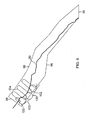
- the UAV 74 when commanded to execute a chase plan 68 the UAV 74 moves along a straight path 88 that may be parallel to the target's path of travel 80 or at an angle toward the target's path of travel 80.
- the chase plan 68 is used for targets 72 moving faster than the UAV 74.
- the UAV 74 By moving along a straight path 88 generally toward the target 72, the UAV 74 is enabled to catch up to, or at least stay with, a fast-moving target 72.
- predictive logic establishes a lead or lag pursuit plan based upon ownship position and target kinematics in order to maximize the camera time on target. Predictions for camera position can also be generated to keep the camera on target while the chase ensues.
- the target kinematics which are contained in the target state input 32 ( Figure 1 ), may be given to the Stalker system in several different modes.
- One mode is from a cooperative target.
- the target may be located using GPS or tracked by an external source.
- Another mode is the operator tracking the moving target via joystick on an image.
- Another mode is tracking the object internally from external sensor reports such as electronic support measures (ESM), radar, automatic/assisted target recognition (ATR) feeds, identify friend/foe (IFF) or other kinematic updates.
- ESM electronic support measures
- ATR automatic/assisted target recognition
- IFF friend/foe
- the first and third of these methods are stable and can be used in the goal and planning cycles as is.
- the second method which involves an operator and a joystick, may produce noisy data that is preferably smoothed in order to obtain a clear track for the target.
- a plurality of dots 90 represent known locations of the target taken at various sampling intervals.
- the heavy black line 92 in Figure 5 represents the smoothed trajectory of the target based on the data points 90.
- the data points 90 are provided by a UAV that is commanded to follow a progression of orbits 94 shown as ellipses in Figure 5 .
- the dashed line 96 indicates the actual flight path of the UAV as it transitions between the commanded orbits.
- the UAV may be commanded to search for targets.
- the UAV In the search mode of operation, the UAV automatically searches a designated region, which may have any shape, including a circle, an ellipse, a polygon or any other shape. When searching, the UAV may limit visual and aural signatures to reduce the likelihood of the UAV being discovered.
- the system may include a region search module 52 ( Figure 1 ).
- the region search module 52 provides information including search boundaries and search patterns.
- a boundary may describe a specific region which as previously stated, may have any shape.
- a boundary may be based on restricted airspace, international borders, terrain, or man-made obstructions. Search patterns may be random or systematic as described further.
- the planner 42 may be configured to use the information from the region search module to generate a region search plan to allow the UAV to scan an area.
- the region search module 52 establishes search boundaries, which may be loaded from the command module 54. While searching, it is advantageous for the UAV to avoid entering restricted airspace, avoid crossing over international borders into the airspace of uncooperative nations, and avoid collisions with terrain and man-made obstructions. Thus, the region search module 52 in conjunction with the command module 54 determines advantageous search patterns while accounting for terrain avoidance, border avoidance, obstruction avoidance, and RF link masking. As described above, in certain embodiments the command module 54 includes data such as topographical terrain maps and locations of borders and obstructions that the planner 42 and the region search module 52 can access to assist in avoiding collisions/crashes and crossing into no fly zones.
- the system 20 compares the video signal 26 from the UAV with video from previous searches to locate possible targets.
- the system 20 may also process the video stream to locate new hot spots (using, for example, infrared scans), and identify pixel changes to detect scene changes.
- the system 20 may scan for infrared signatures, and may identify differences in the search area in the electro-optical (EO), infrared (IR) and electronic warfare (EW) bands to spot new targets in the area.
- EO electro-optical
- IR infrared
- EW electronic warfare
- the system 20 may process these inputs using the ATR/Trainer module 62 to identify known targets of opportunity. These functions may operate autonomously to detect and locate targets.
- additional data may be collected.
- the UAV may follow one or more of the navigation plans outlined above (loiter 64, weave 66, chase 68) to collect sensor data while avoiding discovery of the UAV. Once desired data has been collected, the search pattern may resume.
- the planner 42 and the region search module 52 may command the UAV to fly in a random fashion, following headings selected at random, and/or changing from one heading to the next at random intervals.
- Such random flight increases the difficulty of targeting the UAV from the ground, making it less likely that the UAV will be lost to enemy fire. Random flight also confuses ground forces as to the makeup, intended target(s) and number of UAVs covering an area, and makes it difficult for enemy forces to determine the launch/recovery location(s) of UAVs.
- the planner 42 and the region search module 52 may command the UAV to follow a systematic search pattern.
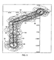
- Figure 6 illustrates one such systematic pattern.
- the region search module 52 ( Figure 1 ) establishes search boundaries 98. As illustrated, the search boundaries overlap an international border 99 with a hostile nation.
- the planner module 42 works together with at least the command module 54 to establish a travel path for the UAV that keeps the UAV from crossing the border 99.
- the UAV follows a travel path represented by a series of loiter circles 100 joined by tangent lines 102.
- the circles 100 and lines 102 keep the UAV on one side of the border 99.
- the camera follows a scanning path 104 represented by a series of oppositely oriented U's that cross the border 99.
- the UAV moves from one loiter circle 100 to the next while the camera scans in the repeating U pattern 104 shown.
- This pattern of border avoidance is known as "lawn mowing," as it is analogous to a person who looks over his or her neighbor's fence as he or she mows his or her own lawn.
- the flight path traced by the UAV may include loiter circles 100 as shown in Figure 6 , and it may also include the weave and chase plans described above.
- the illustrated embodiment of the present system 20 may include a self-calibration planner module 106 configured to calibrate navigational sensors aboard the air vehicle. For example, at designated intervals the UAV may be commanded to enter a self-calibration mode. In this mode, the UAV loiters in a circle around a fixed surveyed location. In each quadrant of the loiter circle, the system 20 generates camera pointing commands at the fixed location. External sensors, such as GPS, are used to precisely locate the fixed target so that camera pointing errors can be measured. Differences between where the camera should be pointing and where it is actually pointing are then resolved so that target location errors are reduced and weapons probability of kill (PK) is increased.
- PK weapons probability of kill
- This calibration routine can be executed around a 360° sweep of the fixed location to characterize the repeatable errors in navigation and camera angle pointing.
- a characterization table may then be generated that can be used when calculating target location error (TLE) for a given target, as well as when compensating for camera pointing errors at known coordinates from other systems.
- TLE target location error
- the UAV may be commanded to self calibrate shortly after takeoff/launch.
- the UAV may fly in a circle about the mother ship, which may include differential GPS to precisely locate the mother ship.
- the UAV may also be commanded to self calibrate at one or more points during its mission. For example, the UAV may also be commanded to self calibrate at regular intervals.
- the illustrated embodiment of the present system 20 further may include a configuration manager module 108 configured to save a data configuration within the system so that the data configuration can be used in the future.
- the configuration manager 108 in combination with a storage device 110, saves one or more configurations of the present system 20.
- the configurations may include operator inputs and target characteristics. By storing these configurations on the storage device 110, the configuration manager 108 can quickly recall them when the system 20 is restarted so that the configurations do not need to be learned again.
- the illustrated embodiment of the present system 20 further includes a record/playback module 112.
- the record/playback module 112 may be configured to record data associated with a tracking operation, for example, as the UAV(s) tracks various targets. The recorded data may be played back later to assist in evaluating the overall performance of the system 20.
- the present system 20 may include an internet protocol-(IP) based addressing scheme.
- IP internet protocol-(IP) based addressing scheme.
- each UAV in the system 20 is identifiable by a unique IP address, and all other UAVs and operators in the system 20 can communicate with each UAV using those addresses.
- IP internet protocol-(IP) based addressing scheme.
- IP internet protocol-(IP) based addressing scheme.
- each UAV in the system 20 is identifiable by a unique IP address, and all other UAVs and operators in the system 20 can communicate with each UAV using those addresses.
- IP internet protocol-(IP) based addressing scheme.
- each UAV in the system 20 is identifiable by a unique IP address, and all other UAVs and operators in the system 20 can communicate with each UAV using those addresses.
- This addressing scheme enables multiple UAVs to be incorporated into the system 20 regardless of what type of control system may have been previously built into each UAV. For instance, a UAV may have been manufactured by a first entity, and
- the present system 20 includes a set of utilities 114.
- Utilities 114 include a set of math functions and transforms that each of the modules may reference to perform the calculations to enable the Stalker system 20 to work.
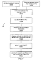
- FIG 7 shows a process flow diagram 116 for autonomously tracking a target using a UAV.
- the process steps may be implemented using the various Stalker system 20 modules described above.
- Process flow 116 assumes that system 20 ( Figure 1 ) and its various modules are initialized and functional.
- step S118 video signals (for example, 26) are received from a UAV (not shown).
- ATR module 22 receives the video signal.
- ATR module 22 analyzes the video signals and generates ATR information as an output for an integration module (for example, MSI 24).
- MSI 24 integration module
- step S120 UAV state and target state information is received by MSI module 24.
- the MSI module 24 receives the ATR information, air vehicle state information, and target state information, and processes the inputs. For example, the MSI module 24 integrates the target state, UAV state and the filtered video information from ATR module 22 and in step S124, MSI module 24 produces track information. For example, MSI module 24 may generate a track file. As discussed above, the track file may include information regarding UAV and target kinematics, estimates for data accuracy, target related information, for example, size, class, target type, whether target is cooperative or non-cooperative or any other information.
- step S126 future UAV and target positions are predicted after comparing track file information with previous predictions.
- step S1208 future UAV states are predicted and either UAV plan is created (if one does not exist) or an existing UAV plan is modified.
- planner module 42 creates and modifies the UAV plan.
- the plan may be based on inputs received from one or more modules, for example, target module 36, ownship module 38, weave corridor module 48, loiter circle module 50, legs module 46, region search module 52, command module 54 and camera module 56 that are described above.
- the plan itself may be a model to predict future UAV states.
- the plan may include commands to generate a travel path for the UAV.
- the method may further comprise at least one of generating a weave plan; generating a loiter plan; generating a region search plan; analyzing an anticipated path of travel for the UAV and determining whether the path crosses into any restricted airspace or intersects any obstructions; cataloging information about the target; calibrating navigational sensors aboard the UAV; predicting a flight path for the UAV; and recording data associated with a tracking operation.
- step S 130 the plan is verified and validated.
- the plan is validated by the command module.
- camera control commands and navigation commands are generated in step S 132. Examples of various inputs/outputs for implementing and executing the process steps of Figure 7 are described above.
Abstract
Description
- The present disclosure relates to control of unmanned air vehicles (UAVs), tracking of moving targets and surveillance of areas, stationary targets and moving targets.
- Aerial surveillance and tracking includes the use of unmanned air vehicles. Currently, human operators remotely control UAVs. The operators must steer both the UAV and the camera/surveillance payload in order to maintain tracking and positive identification of a moving target. Positive identification may require no interruptions or obstructions in visual observation of the target. This practice is labor intensive, and therefore expensive. Usually two operators track a single target, enabling one operator to control flight and the other operator to control camera pointing, focus, zoom, etc. And in military applications involving high value targets, such as known terrorists, usually two UAVs are dedicated to the target, thus requiring four operators. Remotely controlling UAVs with human operators is also prone to loss of positive identification due to bad vehicle position or bad camera angle. Current methods also do not adequately support real time collection of target attribute data. In addition, the operators must pay special attention to no fly zones, restricted airspace and obstructions, further increasing the difficulty of maintaining an uninterrupted track.
- The embodiments of the present system and methods for autonomous tracking and surveillance have several features, no single one of which is solely responsible for their desirable attributes. Without limiting the scope of the present embodiments as expressed by the claims that follow, their more prominent features now will be discussed briefly. After considering this discussion, and particularly after reading the section entitled "Detailed Description", one will understand how the features of the present embodiments provide advantages, which include a reduction in the number of human operators needed to operate the system, which in turn translates into cost savings, a reduction in the likelihood that tracked targets will be lost, a decrease in the risk that UAVs will be lost due to crashes/collisions, and a decrease in the risk that UAVs will enter no fly zones.
- One aspect of the present system and methods for autonomous tracking and surveillance includes the realization that current systems for tracking and surveillance are heavily dependent upon human operators. This dependence upon humans is costly, and subject to losses of target/track data due to bad vehicle position or bad camera angle. Human error is frequently to blame for these losses. Accordingly, a system and methods for automating surveillance, targeting and tracking functions would save costs and reduce errors.
- One embodiment of the present system for autonomously tracking a target from an air vehicle comprises an automatic target recognition (ATR) module configured to receive video information, process the video information, and produce ATR information including target information. The system further comprises a multi-sensor integrator (MSI) module configured to receive the ATR information, an air vehicle state input and a target state input, process the inputs and produce track information for the target. The system further comprises a target module configured to receive the track information, process the track information, and produce predicted future state target information. The system further comprises an ownship module configured to receive the track information, process the track information, and produce predicted future state air vehicle information. The system further comprises a planner module configured to receive the predicted future state target information and the predicted future state air vehicle information and generate travel path information including flight and camera steering commands for the air vehicle.
- One embodiment of the present methods of autonomously tracking a target from an airborne vehicle comprises the steps of receiving video information input to an automatic target recognition (ATR) module, processing the video information, and producing ATR information. The method further comprises the steps of receiving the ATR information, air vehicle state information and target state information as inputs to a multi-sensor integrator (MSI), processing the inputs and producing track information. The method further comprises the steps of receiving the track information as an input to a target module, processing the track information, predicting a future state of the target and producing target information. The method further comprises the steps of receiving the track information as an input to an ownship module, processing the track information, predicting a future state of the air vehicle and producing ownship information. The method further comprises the steps of receiving the target information and the ownship information as inputs to a planner module and generating a travel path for the air vehicle.
- The features, functions, and advantages of the present embodiments can be achieved independently in various embodiments, or may be combined in yet other embodiments.
- The embodiments of the present system and methods for autonomous tracking and surveillance now will be discussed in detail with an emphasis on highlighting the advantageous features. These embodiments depict the novel and non-obvious system and methods shown in the accompanying drawings, which are for illustrative purposes only. These drawings include the following figures, in which like numerals indicate like parts:
-
Figure 1 is a functional block diagram of one embodiment of the present system and methods for autonomous tracking and surveillance; -
Figure 2 is a schematic view of a loiter circle according to one embodiment of the present system and methods for autonomous tracking and surveillance; -
Figure 3 is a schematic view of a weave plan according to one embodiment of the present system and methods for autonomous tracking and surveillance; -
Figure 4 is a schematic view of a chase plan according to one embodiment of the present system and methods for autonomous tracking and surveillance; -
Figure 5 is a schematic view of a method of smoothing noisy tracking data according to one embodiment; -
Figure 6 is a schematic view of a systematic search pattern in which the UAV remains on one side of a border while capturing visual images across the border according to one embodiment; -
Figure 7 is a process flow diagram for autonomously tracking a target using a UAV according to one embodiment; and -
Figure 8 is a schematic view of one embodiment of the present system including a UAV and a ground station. - Embodiments of the present system and methods for autonomous tracking and surveillance are configured to enable an air vehicle to continuously observe stationary targets and track moving targets while maintaining a low risk that the surveillance asset will be discovered. The air vehicle may be an unmanned air vehicle (UAV), including but not limited to, an unmanned aircraft. By way of example only, a UAV will be further described for one embodiment of the invention. The targets may be ground-based, airborne and/or seaborne. The targets may be fixed structures, such as buildings, and may even be subsurface. The automated UAVs may also conduct general surveillance of an area, such as for defense of a base or fleet, and for monitoring roadsides for improvised explosive devices (IEDs) to protect ground-based convoys. The present system may be applied in both military and civilian environments. For example, the military may use the system to survey or observe hostile areas in search of military targets, or a police department may use the system to track fleeing suspects.
- The system accepts target data and UAV data (and may accept other data, such as obstruction data and/or "blue force" data from the UAV or a ground station). The system then determines the best navigation route to maintain an advantageous slant range to the target for high quality camera imaging and a low probability of intercept (LPOI). The system then computes trajectories/flight paths to reduce the likelihood of discovery of the UAV (also referred to herein as "ownship"). The system may incorporate numerous tracking and maneuver techniques, including weaves, orbits, escapes, and lead/lag pursuit course estimations. The system also controls the camera aboard the UAV to maintain uninterrupted visual contact with the target. The system is adapted to control both navigation and camera functions simultaneously.
- Because the present system is automated, it drastically reduces the workload of any operator(s) monitoring the system. The system thus enables tracking of high value moving targets while reducing the likelihood of a loss of positive identification (interruption in target viewing) during target tracking. The operator can "fly the camera," because he or she is relieved of the dual duty of navigating the UAV and maintaining the desired pointing of the camera. The operator is thus able to focus on stalking targets, scanning borders, looking for IEDs, etc. The system also enables a single operator to track multiple moving targets simultaneously, increasing the probability of engaging a high value target after an external attack or a base intrusion incident. Because one operator working at a single location, such as an Insitu Multiple UAV Software Environment (IMUSE) station, may track multiple targets, the present system reduces the logistical footprint necessary for target tracking. The present system also allows an operator to control multiple UAVs to track maritime targets. It can establish a visual identification area around deep sea and littoral fleets to monitor, track and identify small or large moving objects.
- In one embodiment, a system (also referred to herein as a "Stalker system") and associated methods provide automatic generation of UAV and camera steering controls for target following. The Stalker system itself may be implemented as software executable code, specialized application specific integrated circuits (ASICs), or a combination thereof, where some functions are implemented in hardware and others in executable code. In a high-level sense, the Stalker system can operate as a finite state machine where the states are steps in a plan to achieve a certain desired trajectory. The Stalker system accepts target and UAV state updates, and when engaged may be queried for UAV and camera commands. Each UAV command query checks for a planning state transition and may output a new UAV steering command depending upon the selected mode.
- Embodiments of the Stalker system support at least four main functions. One function is generating UAV and camera positions and orientations for stalking a cooperative moving target. A cooperative moving target is one that actively publishes its own geodetic position, as is typical of friendly forces. Another function is generating UAV and camera position and orientation commands for stalking a non-cooperative moving target, whether the tracking is autonomous, or by an operator using a camera joystick. A non-cooperative moving target is one whose position must be observed through the use of electronic sensors and operator inputs, as is typical of hostile forces. Another function is generating UAV and camera position and orientation commands for automatic camera and position calibration to reduce target location errors. Another function is generating UAV and camera position and orientation commands for stalking a roadside or a search area, and generating subsequent commands to revisit targets if targets of interest are detected in those specified areas.
- One goal of the Stalker system is to establish and maintain a range to target between preset minimum and maximum values. These values are specified to provide a large number of pixels on the target, while maintaining noise and visual signatures that the target is not likely to detect. Another goal of the Stalker system is to maintain an uninterrupted line of sight to the target, taking care to avoid obstructing viewing angles with the wing and fuselage.
- In embodiments of the present system, a UAV (not shown) includes at least one video camera, which may be a digital camera. For simplicity the singular form of camera will be used throughout, although those of ordinary skill in the art will appreciate that the UAV may include more than one camera. The UAV further includes a plurality of sensors. A first subset of the sensors detects various states of the UAV, while a second subset of the sensors detects various states of the target. The detected states may include, but are not limited to position, orientation, heading, speed, acceleration and other kinematic states, size, type and/or class of the target, and other states. A video signal generated by the camera and signals generated by the sensors are transmitted to hardware components that use the signals to visualize and track the target.
Figure 1 illustrates some of these components. Some or all of the components illustrated inFigure 1 may be located on the UAV or they may be located at one or more ground stations. The components may also be split between the UAV and one or more ground stations.Figure 8 illustrates an example embodiment of the present system including aUAV 74 and aground station 134. - As used in this disclosure, the terms "component", "module", "system," and the like are intended to refer to a computer-related entity, either hardware, a combination of hardware and software, software, or software in execution. For example, a component may be, but is not limited to being, a process running on a processor, a processor, a hardware component, an object, an executable, a thread of execution, a program, and/or a computing system. Also, these components can execute from various computer readable media having various data structures stored thereon. Computer executable components (or code) can be stored, for example, on computer readable media including, but not limited to, an ASIC (application specific integrated circuit), CD (compact disc), DVD (digital video disk), ROM (read only memory), floppy disk, hard disk, EEPROM (electrically erasable programmable read only memory) and memory stick in accordance with the claimed subject matter.
- With reference to
Figure 1 , one embodiment of thepresent system 20 includes an automatic target recognition (ATR)module 22 and a multi-sensor integration (MSI)module 24. As used herein, the term module may include any combination of hardware, firmware, and software to implement the functions described. TheATR module 22 receives avideo signal 26 from the UAV (not shown). TheATR module 22 includes instructions to analyze thevideo signal 26 and generates anoutput 28 that it sends to theMSI module 24. In addition to theATR output 28, theMSI module 24 also receives aUAV state signal 30 and atarget state signal 32. Thesignals - The
MSI module 24 receivesinputs output 34. TheMSI module output 34 is referred to herein as track information or a track file. Thetrack file 34 includes not only information regarding the kinematics of the UAV and the target, but also estimates of the accuracy of the data in thetrack file 34, and also target identification data, such as the size, class, and/or type of the target, whether the target is cooperative or non-cooperative, etc. Those of ordinary skill in the art will appreciate that the track file may or may not be stored in memory for subsequent retrieval. The word "file" is used broadly herein and does not imply that the process of producing thetrack file 34 includes an additional step of storing the file in memory. - The
MSI module 24 sends thetrack file 34 to atarget module 36 and anownship module 38. Thetarget module 36 processes the data in thetrack file 34 relating to the current state of the target, and compares (Gates) this data to previous predictions made regarding the current state of the target. Thetarget module 36 uses all available data and comparisons between past predictions and current states, and makes further predictions about future states of the target. Gating intarget module 36 produces anoutput 40 that it sends to aplanner module 42. -
Ownship module 38 processes the data in thetrack file 34 relating to the current state of the UAV, and compares (Gates) this data to previous predictions (not shown) made regarding the current state of the UAV. Discrepancies in the predicted state of the UAV versus its current state may be due to, for example, winds blowing the UAV off its intended course. Theownship module 38 uses all available data and comparisons between past predictions and current states, and makes further predictions about future states of the UAV. Gating inownship module 38 then produces anoutput 44 that it sends to theplanner module 42. - The
planner module 42 combines thetarget module input 40 and theownship module input 44 to generate travel path information. In one embodiment, theplanner module 42 may use additional data provided by at least one of alegs module 46, aweave corridor module 48, aloiter circle module 50, aregion search module 52, acommand module 54 and a camera module 56. The functions of each of these modules are described in detail below. Based on the various inputs, theplanner module 42 builds a model for predicting future UAV states given its current state and the currently active command. Theplanner module 42 uses the model to predict future UAV states at certain critical times, and to establish goals, which in turn produce predicted UAV and camera positions. Theplanner 42 also combines all data to produce commands for course corrections and/or pattern adjustments for the UAV. These adjustments are described below with respect to three top-level goal states for the UAV. Thepresent system 20 uses all of the functions described above extensively in stalking both cooperative and non-cooperative targets. - With continued reference to
Figure 1 , thelegs module 46 may be configured to predict a flight path for the UAV. For example, thelegs module 46 may predict a long-term flight path for the UAV. In support of the long-term predictions, thelegs module 46 may also predict short-term legs that together make up the long-term flight path. Thelegs module 46 communicates its predictions to theplanner module 42 to aid theplanner module 42 in creating UAV commands to control the flight of the UAV. - With continued reference to
Figure 1 , in certain embodiments thecommand module 54 may include data regarding the UAV mission environment. This data may include, for example, topographical terrain maps, locations of international borders, locations of obstructions and other data. The data may also include the locations and kinematics of other aircraft in the vicinity. By accessing the data in thecommand module 54, thepresent system 20 can command the UAV to maintain an uninterrupted track on a target while avoiding collisions/crashes and crossing into no fly zones. For example, thecommand module 54 may be configured to analyze an anticipated path of travel for the air vehicle and determine whether the path crosses into any restricted airspace or intersects any obstructions. Thecommand module 54 may also validate UAV commands to ensure that the UAV is capable of executing the commands to achieve the desired flight path. For example, if a UAV command indicates that the UAV should execute a very tight turn that is beyond the UAVs physical limits, the validity function of thecommand module 54 will reject the command as being impossible for the UAV to execute. - With continued reference to
Figure 1 , thepresent system 20 further comprises a camera module 56 and acamera commander module 58. The camera module 56 may be configured to predict future camera imaging characteristics, such as pointing, focus and zoom for a camera aboard the UAV. The camera module 56 communicates with theplanner module 42 and generates outputs for thecamera commander module 58. Thecamera commander module 58 generatescommands 60 for the camera, such as where to point and how to focus and zoom. Together the camera module 56 and thecamera commander module 58, in conjunction with theplanner module 42, automatically control camera functions in order to obtain an uninterrupted and high quality image of the target. - In certain embodiments the camera and/or sensors may provide additional information beyond that generally provided by traditional visual surveillance. For example, the camera/sensors may provide three-dimensional visual representations of the target. These three-dimensional views are enhanced by multi-aspect viewing of the target in accordance with the loiter, weave, and chase surveillance patterns described below. The camera/sensors may further provide thermal signature information, infrared signature information, color information, etc. for the target. All information collected by the camera/sensors may be provided to an ATR/Trainer module 62 (
Figure 1 ), described below, for use in future target identifications. Multiple aspect coverage of the target enables the automatic target recognition function of thepresent system 20, described below, to recognize geometric aspects of the target that are not available in two-dimensional or single aspect imagery, drastically decreasing the time necessary for thepresent system 20 to recognize the target. - While in cooperative and non-cooperative stalking modes, and prior to receiving either the
UAV state input 30 or thetarget state input 32, theStalker system 20 is in a startup state. Once thesystem 20 has received both theUAV state input 30 and thetarget state input 32, thesystem 20 is queried for a steering command and/or a camera command. Thesystem 20 then transitions from startup to a top-level goal state. These top-level goal states include loiter 64, weave 66, and chase 68, each of which are illustrated inFigures 2-4 , respectively. Those of ordinary skill in the art will appreciate that additional top-level goal states may be provided depending upon the state of the target. - Each top-level goal state corresponds to a dynamically generated plan to attain a desired UAV trajectory for advantageous imaging quality while controlling visual and audio signatures of the UAV. Each top-level goal state is also intended to prevent over flight of the target, which could cause the target to detect the UAV. Consistent with these objectives, then, at least target speed and UAV speed determine the top-level goal. For example, if target speed is zero or near zero, the goal may be to loiter in a
circle 70, as illustrated inFigure 2 . Theloiter path 70 may encircle thetarget 72, or it may be somewhere in the vicinity of thetarget 72. Further, theloiter path 70 need not be a circle, but could be some other shape. If target speed is not near zero and is less than UAV speed, the goal may be to weave back and forth behind thetarget 72, as illustrated inFigure 3 . If target speed is high, the goal may be to chase thetarget 72, as illustrated inFigure 4 . The top-level goal changes dynamically as thetarget 72 accelerates, decelerates, stops and starts. - Corresponding to each top-level goal are goal-specific planning states, or steps to achieve the top-level goal. These steps are mapped to steering commands that are scheduled to be sent to the UAV at specified times. Planning a UAV trajectory involves reasoning in both space and time and predicting how the UAV will respond to commands. Therefore, accurately planning a UAV trajectory preferably includes an estimate of the command time latency and a model of how the UAV will maneuver when it executes the command.
- When loitering, each UAV maneuver is executed pursuant to commands generated by the
planner module 42 in conjunction with the loiter circle module 50 (Figure 1 ). Theloiter circle module 50 makes predictions regarding the future state of the UAV, which theplanner module 42 uses to generate a loiter plan including loiter commands for the UAV. The loiter plan may be designed to maintain a desired distance between the UAV and the target while the target is stationary. In the case of a circular loiter path 70 (Figure 2 ), a loiter command has three parts: a turn center (a co-altitude geodetic location), a turn radius, and a turn direction (clockwise or counter-clockwise as viewed from above). Thus, when thesystem 20 determines that the UAV should loiter, as when thetarget 72 is stopped, theplanner 42 and theloiter circle module 50 generate at least one loiter point for the UAV. The loiter point(s) is/are sent to the hardware that controls the UAV's movement along with camera pointing commands. - In one embodiment, if the aircraft is outside the commanded
loiter circle 70 then it executes a loiter command as follows. With reference toFigure 2 , theUAV 74 makes aninitial turn 76 so that its direction of flight is tangential to theloiter circle 70 and is compatible with the commanded turn direction. TheUAV 74 then flies straight to thetangent point 78. Upon reaching thetangent point 78 theUAV 74 flies around theloiter circle 70 until commanded to do otherwise. Each of these UAV maneuvers are executed pursuant to commands generated by theplanner module 42 in conjunction with the loiter circle module 50 (Figure 1 ). - When the
loiter path 70 encircles thetarget 72, the loiter plan advantageously provides full 360° imaging of thetarget 72. Images captured and other sensor readings taken from such 360° degree sweeps can advantageously provide full geometric data regarding thetarget 72 to theATR module 22. In one embodiment the ATR/Trainer module 62 (Figure 1 ) may be configured to catalog information about the target. For example, the ATR/Training module 62 may automatically log the target data and attempt to identify the target. If the target cannot be identified, then the ATR/Trainer module 62 classifies the target as a new entity and records the data. This data may be shared system wide, including continuous dissemination to other UAVs in the field. Thepresent system 20 thus rapidly increases its knowledge base as UAVs in the field gather more and more data about new targets and share that data with other UAVs in the field. - With reference to
Figure 3 , when commanded to execute aweave plan 66 theUAV 74 moves back and forth across the target's path oftravel 80, and behind thetarget 72. When weaving, each UAV maneuver is executed pursuant to commands generated by theplanner module 42 in conjunction with the weave corridor module 48 (Figure 1 ). Theweave corridor module 48 makes predictions regarding the future state of theUAV 74, which theplanner module 42 uses to generate aweave plan 66 including weave commands for theUAV 74. Again, theweave plan 66 is generally used fortargets 72 that are traveling slower than or about the same speed as theUAV 74. Theweave plan 66 provides for a snake-like motion behind the movingtarget 72, keeping visual and audio signatures at levels not likely to be detected by thetarget 72. The crisscrossingpath 82 provides wide aspect coverage of the aft and sides of thetarget 72 for advantageous intelligence and potential ATR data. This technique also makes it extremely difficult for occupants of thetarget 72 to spot theUAV 74 due to their orientation away from theUAV 74. - The
weave plan 66 may includeboundaries 84 that extend substantially in the same direction as the target's path oftravel 80. Theweave corridor module 48 and/or thecommand module 54 may provide theseboundaries 84. Theboundaries 84 may be established to maintain a desired distance between theUAV 74 and thetarget 72 while the target is moving, and/or, theboundaries 84 may coincide with national borders, no fly zones, physical obstructions, etc. When theUAV 74 approaches one of theboundaries 84, it may enter a circular path oftravel 86 where it may execute one or more loops around thecircle 86 before heading back across the target's path oftravel 80 toward theopposite boundary 84. Those of ordinary skill in the art will appreciate that theweave plan 66 may embody other patterns besides that illustrated inFigure 3 . For example, theUAV 74 may weave back and forth without executing any of the substantiallycircular loops 86 near theboundaries 84. - With reference to
Figure 4 , when commanded to execute achase plan 68 theUAV 74 moves along astraight path 88 that may be parallel to the target's path oftravel 80 or at an angle toward the target's path oftravel 80. Again, thechase plan 68 is used fortargets 72 moving faster than theUAV 74. By moving along astraight path 88 generally toward thetarget 72, theUAV 74 is enabled to catch up to, or at least stay with, a fast-movingtarget 72. In one embodiment of thepresent system 20, predictive logic establishes a lead or lag pursuit plan based upon ownship position and target kinematics in order to maximize the camera time on target. Predictions for camera position can also be generated to keep the camera on target while the chase ensues. - The target kinematics, which are contained in the target state input 32 (
Figure 1 ), may be given to the Stalker system in several different modes. One mode is from a cooperative target. For example, the target may be located using GPS or tracked by an external source. Another mode is the operator tracking the moving target via joystick on an image. Another mode is tracking the object internally from external sensor reports such as electronic support measures (ESM), radar, automatic/assisted target recognition (ATR) feeds, identify friend/foe (IFF) or other kinematic updates. The first and third of these methods are stable and can be used in the goal and planning cycles as is. The second method, which involves an operator and a joystick, may produce noisy data that is preferably smoothed in order to obtain a clear track for the target. With reference toFigure 5 , a plurality ofdots 90 represent known locations of the target taken at various sampling intervals. The heavyblack line 92 inFigure 5 represents the smoothed trajectory of the target based on the data points 90. The data points 90 are provided by a UAV that is commanded to follow a progression oforbits 94 shown as ellipses inFigure 5 . The dashedline 96 indicates the actual flight path of the UAV as it transitions between the commanded orbits. - With reference to
Figure 1 , in certain embodiments of thepresent system 20 the UAV may be commanded to search for targets. In the search mode of operation, the UAV automatically searches a designated region, which may have any shape, including a circle, an ellipse, a polygon or any other shape. When searching, the UAV may limit visual and aural signatures to reduce the likelihood of the UAV being discovered. In the search mode of operation, the system may include a region search module 52 (Figure 1 ). Theregion search module 52 provides information including search boundaries and search patterns. A boundary may describe a specific region which as previously stated, may have any shape. A boundary may be based on restricted airspace, international borders, terrain, or man-made obstructions. Search patterns may be random or systematic as described further. Theplanner 42 may be configured to use the information from the region search module to generate a region search plan to allow the UAV to scan an area. - In one embodiment, the
region search module 52 establishes search boundaries, which may be loaded from thecommand module 54. While searching, it is advantageous for the UAV to avoid entering restricted airspace, avoid crossing over international borders into the airspace of uncooperative nations, and avoid collisions with terrain and man-made obstructions. Thus, theregion search module 52 in conjunction with thecommand module 54 determines advantageous search patterns while accounting for terrain avoidance, border avoidance, obstruction avoidance, and RF link masking. As described above, in certain embodiments thecommand module 54 includes data such as topographical terrain maps and locations of borders and obstructions that theplanner 42 and theregion search module 52 can access to assist in avoiding collisions/crashes and crossing into no fly zones. - In some embodiments, while the UAV searches, the
system 20 compares thevideo signal 26 from the UAV with video from previous searches to locate possible targets. Thesystem 20 may also process the video stream to locate new hot spots (using, for example, infrared scans), and identify pixel changes to detect scene changes. Thesystem 20 may scan for infrared signatures, and may identify differences in the search area in the electro-optical (EO), infrared (IR) and electronic warfare (EW) bands to spot new targets in the area. Thesystem 20 may process these inputs using the ATR/Trainer module 62 to identify known targets of opportunity. These functions may operate autonomously to detect and locate targets. Once a target is located, additional data may be collected. During the collection of additional data the UAV may follow one or more of the navigation plans outlined above (loiter 64, weave 66, chase 68) to collect sensor data while avoiding discovery of the UAV. Once desired data has been collected, the search pattern may resume. - In the search mode, the
planner 42 and theregion search module 52 may command the UAV to fly in a random fashion, following headings selected at random, and/or changing from one heading to the next at random intervals. Such random flight increases the difficulty of targeting the UAV from the ground, making it less likely that the UAV will be lost to enemy fire. Random flight also confuses ground forces as to the makeup, intended target(s) and number of UAVs covering an area, and makes it difficult for enemy forces to determine the launch/recovery location(s) of UAVs. - Alternatively, the
planner 42 and theregion search module 52 may command the UAV to follow a systematic search pattern.Figure 6 illustrates one such systematic pattern. The region search module 52 (Figure 1 ) establishessearch boundaries 98. As illustrated, the search boundaries overlap aninternational border 99 with a hostile nation. Thus, theplanner module 42 works together with at least thecommand module 54 to establish a travel path for the UAV that keeps the UAV from crossing theborder 99. As shown, the UAV follows a travel path represented by a series ofloiter circles 100 joined bytangent lines 102. Thecircles 100 andlines 102 keep the UAV on one side of theborder 99. However, the camera follows ascanning path 104 represented by a series of oppositely oriented U's that cross theborder 99. The UAV moves from oneloiter circle 100 to the next while the camera scans in the repeatingU pattern 104 shown. Thus, while the UAV never violates the airspace of the hostile nation, the camera is nevertheless able to capture visual images within the hostile nation. This pattern of border avoidance is known as "lawn mowing," as it is analogous to a person who looks over his or her neighbor's fence as he or she mows his or her own lawn. The flight path traced by the UAV may include loitercircles 100 as shown inFigure 6 , and it may also include the weave and chase plans described above. - With reference to
Figure 1 , the illustrated embodiment of thepresent system 20 may include a self-calibration planner module 106 configured to calibrate navigational sensors aboard the air vehicle. For example, at designated intervals the UAV may be commanded to enter a self-calibration mode. In this mode, the UAV loiters in a circle around a fixed surveyed location. In each quadrant of the loiter circle, thesystem 20 generates camera pointing commands at the fixed location. External sensors, such as GPS, are used to precisely locate the fixed target so that camera pointing errors can be measured. Differences between where the camera should be pointing and where it is actually pointing are then resolved so that target location errors are reduced and weapons probability of kill (PK) is increased. This calibration routine can be executed around a 360° sweep of the fixed location to characterize the repeatable errors in navigation and camera angle pointing. A characterization table may then be generated that can be used when calculating target location error (TLE) for a given target, as well as when compensating for camera pointing errors at known coordinates from other systems. - One instance in which it is advantageous to recalibrate the camera aboard the UAV is shortly after the UAV launches. Whether the UAV takes off from the ground under its own power, is launched from the ground or is launched from an airborne mother ship, the UAV can experience high G-forces during each of these procedures. The G-forces can cause servo errors and generate calibration problems. Therefore, the UAV may be commanded to self calibrate shortly after takeoff/launch. For airborne launches, the UAV may fly in a circle about the mother ship, which may include differential GPS to precisely locate the mother ship. The UAV may also be commanded to self calibrate at one or more points during its mission. For example, the UAV may also be commanded to self calibrate at regular intervals.
- With reference to
Figure 1 , the illustrated embodiment of thepresent system 20 further may include aconfiguration manager module 108 configured to save a data configuration within the system so that the data configuration can be used in the future. For example, theconfiguration manager 108, in combination with astorage device 110, saves one or more configurations of thepresent system 20. For example, the configurations may include operator inputs and target characteristics. By storing these configurations on thestorage device 110, theconfiguration manager 108 can quickly recall them when thesystem 20 is restarted so that the configurations do not need to be learned again. - With continued reference to
Figure 1 , the illustrated embodiment of thepresent system 20 further includes a record/playback module 112. The record/playback module 112 may be configured to record data associated with a tracking operation, for example, as the UAV(s) tracks various targets. The recorded data may be played back later to assist in evaluating the overall performance of thesystem 20. - In certain embodiments, the
present system 20 may include an internet protocol-(IP) based addressing scheme. In such a scheme, each UAV in thesystem 20 is identifiable by a unique IP address, and all other UAVs and operators in thesystem 20 can communicate with each UAV using those addresses. This addressing scheme enables multiple UAVs to be incorporated into thesystem 20 regardless of what type of control system may have been previously built into each UAV. For instance, a UAV may have been manufactured by a first entity, and may be configured for operation according to the first entity's proprietary control system. The IP-based addressing scheme stands in front of the proprietary system so that the UAV can be incorporated into thepresent system 20 without requiring translation between control systems. - With reference to
Figure 1 , in certain embodiments thepresent system 20 includes a set ofutilities 114.Utilities 114 include a set of math functions and transforms that each of the modules may reference to perform the calculations to enable theStalker system 20 to work. -
Figure 7 shows a process flow diagram 116 for autonomously tracking a target using a UAV. As an example, the process steps may be implemented using thevarious Stalker system 20 modules described above.Process flow 116 assumes that system 20 (Figure 1 ) and its various modules are initialized and functional. - Turning in detail to
Figure 7 , in step S118, video signals (for example, 26) are received from a UAV (not shown). In one example,ATR module 22 receives the video signal.ATR module 22 analyzes the video signals and generates ATR information as an output for an integration module (for example, MSI 24). In step S120, UAV state and target state information is received byMSI module 24. - In step S122, the
MSI module 24 receives the ATR information, air vehicle state information, and target state information, and processes the inputs. For example, theMSI module 24 integrates the target state, UAV state and the filtered video information fromATR module 22 and in step S124,MSI module 24 produces track information. For example,MSI module 24 may generate a track file. As discussed above, the track file may include information regarding UAV and target kinematics, estimates for data accuracy, target related information, for example, size, class, target type, whether target is cooperative or non-cooperative or any other information. - In step S126, future UAV and target positions are predicted after comparing track file information with previous predictions.
- In step S128, future UAV states are predicted and either UAV plan is created (if one does not exist) or an existing UAV plan is modified. In one embodiment,
planner module 42 creates and modifies the UAV plan. The plan may be based on inputs received from one or more modules, for example,target module 36,ownship module 38,weave corridor module 48, loitercircle module 50,legs module 46,region search module 52,command module 54 and camera module 56 that are described above. The plan itself may be a model to predict future UAV states. The plan may include commands to generate a travel path for the UAV. For example, the method may further comprise at least one of generating a weave plan; generating a loiter plan; generating a region search plan; analyzing an anticipated path of travel for the UAV and determining whether the path crosses into any restricted airspace or intersects any obstructions; cataloging information about the target; calibrating navigational sensors aboard the UAV; predicting a flight path for the UAV; and recording data associated with a tracking operation. - In step S 130, the plan is verified and validated. In one embodiment, the plan is validated by the command module. Thereafter, camera control commands and navigation commands are generated in step S 132. Examples of various inputs/outputs for implementing and executing the process steps of
Figure 7 are described above. - The above description presents the best mode contemplated for carrying out the present system and methods for autonomous tracking and surveillance, and of the manner and process of practicing them, in such full, clear, concise, and exact terms as to enable any person skilled in the art to which they pertain to practice this system and these methods. This system and these methods are, however, susceptible to modifications and alternate constructions from those discussed above that are fully equivalent. Consequently, this system and these methods are not limited to the particular embodiments disclosed. On the contrary, this system and these methods cover all modifications and alternate constructions coming within the spirit and scope of the system and methods as generally expressed by the following claims, which particularly point out and distinctly claim the subject matter of the system and methods.
Claims (16)
- A system (20) for autonomously tracking a target from an air vehicle, the system comprising:an automatic target recognition (ATR) module (22) configured to receive video information, process the video information, and produce ATR information including target information;a multi-sensor integrator (MSI) module (24) configured to receive the ATR information, an air vehicle state input and a target state input, process the inputs and produce track information for the target;a target module (36) configured to receive the track information, process the track information, and produce predicted future state target information;an ownship module (38) configured to receive the track information, process the track information, and produce predicted future state air vehicle information; anda planner module (42) configured to receive the predicted future state target information and the predicted future state air vehicle information and generate travel path information including flight and camera steering commands for the air vehicle.
- The system of Claim 1, further comprising a weave corridor module (48), wherein the planner is configured to use information provided by the weave corridor module to generate a weave plan (66) for the air vehicle, the weave plan being designed to maintain a desired distance between the air vehicle and the target while the target is moving and while maintaining the air vehicle within predetermined boundaries.
- The system of Claim 2, wherein at least a portion of the boundaries coincide with at least one of a national border, an edge of a no fly zone and a physical obstruction.
- The system of Claim 1, further comprising a loiter circle module (50), wherein the planner (42) is configured to use information provided by the loiter circle module to generate a loiter plan for the air vehicle, the loiter plan being designed to maintain a desired distance between the air vehicle and the target while the target is stationary.
- The system of Claim 1, further comprising a region search module (52), wherein the planner (42) is configured to use information provided by the region search module to generate a region search plan for the air vehicle, the region search plan being designed to allow the air vehicle to scan an area.
- The system of Claim 1, further comprising at least one ofa command module (54) configured to analyze an anticipated path of travel for the air vehicle and determine whether the path crosses into any restricted airspace or intersects any obstructions;an automatic target recognition trainer module (62) configured to catalog information about the target;a self calibration planner module (106) configured to calibrate navigational sensors aboard the air vehicle;a configuration manager module (108) configured to save a data configuration within the system so that the data configuration can be used in the future;a legs module (46) configured to predict a flight path for the air vehicle; anda record/playback module (112) configured to record data associated with a tracking operation.
- The system of Claim 1, further comprising a camera module (56) configured to predict future imaging characteristics for a camera aboard the air vehicle.
- The system of Claim 6, further comprising a camera and a camera commander module (58) configured to control focus and zoom of the camera.
- The system of Claim 1, wherein the air vehicle is an unmanned air vehicle (UAV) (74).
- The system of Claim 1, further comprising a ground station (134).
- The system of Claim 10, wherein at least one of the modules is located at the ground station (134).
- A method of autonomously tracking a target from an airborne vehicle, the method comprising the steps of:receiving video information input to an automatic target recognition (ATR) module (22), processing the video information, and producing ATR information;receiving the ATR information, air vehicle state information and target state information as inputs to a multi-sensor integrator (MSI) (24), processing the inputs and producing track information;receiving the track information as an input to a target module (36), processing the track information, predicting a future state of the target and producing target information;receiving the track information as an input to an ownship module (38), processing the track information, predicting a future state of the air vehicle and producing ownship information; andreceiving the target information and the ownship information as inputs to a planner module (42) and generating a travel path for the air vehicle.
- The method of Claim 12, further comprising the step of storing the track information as a track file (34).
- The method of Claim 12, further comprising at least one ofgenerating a weave plan (66) for the air vehicle, the weave plan (66) being designed to maintain a desired distance between the air vehicle and the target while the target is moving and while maintaining the air vehicle within boundaries;generating a loiter plan for the air vehicle, the loiter plan being designed to maintain a desired distance between the air vehicle and the target while the target is stationary;generating a region search plan for the air vehicle, the region search plan being designed to allow the air vehicle to scan an area;analyzing an anticipated path of travel for the air vehicle and determining whether the path crosses into any restricted airspace or intersects any obstructions.cataloging information about the target;calibrating navigational sensors aboard the air vehicle;predicting a flight path for the air vehicle; andrecording data associated with a tracking operation.
- The method of Claim 12, further comprising the step of predicting, using a camera module (56), future imaging characteristics for a camera aboard the air vehicle.
- The method of Claim 15, wherein the air vehicle further comprises a camera and a camera commander module (58) configured to control focus and zoom of the camera.
Applications Claiming Priority (1)
| Application Number | Priority Date | Filing Date | Title |
|---|---|---|---|
| US11/956,711 US8718838B2 (en) | 2007-12-14 | 2007-12-14 | System and methods for autonomous tracking and surveillance |
Publications (3)
| Publication Number | Publication Date |
|---|---|
| EP2071353A2 true EP2071353A2 (en) | 2009-06-17 |
| EP2071353A3 EP2071353A3 (en) | 2009-06-24 |
| EP2071353B1 EP2071353B1 (en) | 2019-08-07 |
Family
ID=40451024
Family Applications (1)
| Application Number | Title | Priority Date | Filing Date |
|---|---|---|---|
| EP08171682.1A Active EP2071353B1 (en) | 2007-12-14 | 2008-12-15 | System and methods for autonomous tracking and surveillance |
Country Status (2)
| Country | Link |
|---|---|
| US (1) | US8718838B2 (en) |
| EP (1) | EP2071353B1 (en) |
Cited By (29)
| Publication number | Priority date | Publication date | Assignee | Title |
|---|---|---|---|---|
| WO2011114059A1 (en) | 2010-03-18 | 2011-09-22 | Flyway-Media | System and method intended for capturing a video sequence pertaining to a target subject in motion on the basis in particular of an autonomous or semi-autonomous aircraft |
| ES2394540A1 (en) * | 2012-07-26 | 2013-02-01 | Geonumerics, S.L. | Method for the acquisition and processing of geographical information of a path |
| CN103914065A (en) * | 2014-03-24 | 2014-07-09 | 深圳市大疆创新科技有限公司 | Method and device for correcting aircraft state in real time |
| EP2879012A1 (en) * | 2013-11-29 | 2015-06-03 | The Boeing Company | System and method for commanding a payload of an aircraft |
| EP2881824A1 (en) * | 2013-12-06 | 2015-06-10 | BAE Systems PLC | Imaging method and system |
| EP2881823A1 (en) * | 2013-12-06 | 2015-06-10 | BAE Systems PLC | Imaging method and apparatus |
| EP2881709A1 (en) * | 2013-12-06 | 2015-06-10 | BAE Systems PLC | Determining routes for aircraft |
| EP2881827A1 (en) * | 2013-12-06 | 2015-06-10 | BAE Systems PLC | Imaging method and apparatus |
| WO2015082594A1 (en) * | 2013-12-06 | 2015-06-11 | Bae Systems Plc | Determining routes for aircraft |
| WO2015082595A1 (en) * | 2013-12-06 | 2015-06-11 | Bae Systems Plc | Imaging method and apparatus |
| GB2522327A (en) * | 2013-12-06 | 2015-07-22 | Bae Systems Plc | Determining routes for aircraft |
| CN106292720A (en) * | 2015-04-21 | 2017-01-04 | 高域(北京)智能科技研究院有限公司 | A kind of intelligent multi-control flight capture apparatus and flight control method thereof |
| EP3128386A1 (en) * | 2015-08-04 | 2017-02-08 | The Boeing Company | Method and device for tracking a moving target from an air vehicle |
| CN106406327A (en) * | 2016-11-01 | 2017-02-15 | 中国航空无线电电子研究所 | Unmanned aerial vehicle task architecture rapid verification platform |
| WO2017103255A1 (en) * | 2015-12-18 | 2017-06-22 | Antony Pfoertzsch | Device and method for an unmanned flying object |
| CN107144281A (en) * | 2017-06-30 | 2017-09-08 | 飞智控(天津)科技有限公司 | Unmanned plane indoor locating system and localization method based on cooperative target and monocular vision |
| EP3273318A1 (en) * | 2016-07-22 | 2018-01-24 | Parrot Drones | Autonomous system for collecting moving images by a drone with target tracking and improved target positioning |
| US9897417B2 (en) | 2013-12-06 | 2018-02-20 | Bae Systems Plc | Payload delivery |
| WO2018102698A1 (en) * | 2016-12-02 | 2018-06-07 | Adesa, Inc. | Method and apparatus using a drone to input vehicle data |
| EP3299925A3 (en) * | 2016-09-23 | 2018-08-01 | Beijing Xiaomi Mobile Software Co., Ltd. | Method, apparatus and system for controlling unmanned aerial vehicle |
| US10060746B2 (en) | 2014-03-24 | 2018-08-28 | SZ DJI Technology Co., Ltd | Methods and systems for determining a state of an unmanned aerial vehicle |
| EP3387507A4 (en) * | 2015-12-09 | 2018-12-26 | SZ DJI Technology Co., Ltd. | Systems and methods for uav flight control |
| US10203691B2 (en) | 2013-12-06 | 2019-02-12 | Bae Systems Plc | Imaging method and apparatus |
| CN110850455A (en) * | 2019-10-18 | 2020-02-28 | 浙江天尚元科技有限公司 | Track recording method based on differential GPS and vehicle kinematics model |
| DE102019104866A1 (en) * | 2019-02-26 | 2020-08-27 | Rheinmetall Waffe Munition Gmbh | Drone and anti-targeting methods |
| WO2021090312A3 (en) * | 2019-11-06 | 2021-06-17 | Israel Aerospace Industries Ltd. | Line of sight maintenance during object tracking |
| WO2021180520A1 (en) * | 2020-03-13 | 2021-09-16 | Sony Group Corporation | A system, a method and a computer program for generating a digital map of an environment |
| CN113865052A (en) * | 2021-09-30 | 2021-12-31 | 佛山市顺德区美的电子科技有限公司 | Control method, control equipment, air conditioning system and storage medium |
| CN114780915A (en) * | 2022-04-12 | 2022-07-22 | 北京航天驭星科技有限公司 | Method, device and equipment for determining data correctness of collision early warning service platform |
Families Citing this family (130)
| Publication number | Priority date | Publication date | Assignee | Title |
|---|---|---|---|---|
| US20100157056A1 (en) * | 2007-05-20 | 2010-06-24 | Rafael Advanced Defense Systems Ltd. | Tracking and imaging data fusion |
| WO2009019695A2 (en) * | 2007-08-07 | 2009-02-12 | Visionmap Ltd. | Method and system to perform optical moving object detection and tracking over a wide area |
| US9026272B2 (en) | 2007-12-14 | 2015-05-05 | The Boeing Company | Methods for autonomous tracking and surveillance |
| CA2979232A1 (en) * | 2009-02-02 | 2010-10-28 | Aerovironment | Multimode unmanned aerial vehicle |
| WO2010127351A1 (en) * | 2009-05-01 | 2010-11-04 | Aai Corporation | Method, apparatus, system and computer program product for automated collection and correlation for tactical information |
| US9494941B2 (en) * | 2009-06-26 | 2016-11-15 | Luminati Aerospace Llc | Method of guidance of unmanned aerial vehicles |
| US9115996B2 (en) * | 2009-07-29 | 2015-08-25 | Lockheed Martin Corporation | Threat analysis toolkit |
| US8634982B2 (en) * | 2009-08-19 | 2014-01-21 | Raytheon Company | System and method for resource allocation and management |
| AU2010325107B2 (en) | 2009-09-09 | 2016-08-25 | Aerovironment, Inc. | Systems and devices for remotely operated unmanned aerial vehicle report-suppressing launcher with portable RF transparent launch tube |
| US8918230B2 (en) * | 2011-01-21 | 2014-12-23 | Mitre Corporation | Teleoperation of unmanned ground vehicle |
| US8396730B2 (en) * | 2011-02-14 | 2013-03-12 | Raytheon Company | System and method for resource allocation and management |
| DK2681635T3 (en) * | 2011-02-28 | 2022-05-09 | Bea Systems Australia | STEERING COMPUTER FOR AN UNMANNED VESSEL |
| TW201249713A (en) * | 2011-06-02 | 2012-12-16 | Hon Hai Prec Ind Co Ltd | Unmanned aerial vehicle control system and method |
| CN102809969A (en) * | 2011-06-03 | 2012-12-05 | 鸿富锦精密工业(深圳)有限公司 | Unmanned aerial vehicle control system and method |
| TW201328344A (en) * | 2011-12-27 | 2013-07-01 | Hon Hai Prec Ind Co Ltd | System and method for controlling a unmanned aerial vehicle to capture images of a target location |
| CN103188431A (en) * | 2011-12-27 | 2013-07-03 | 鸿富锦精密工业(深圳)有限公司 | System and method for controlling unmanned aerial vehicle to conduct image acquisition |
| FR2985581B1 (en) * | 2012-01-05 | 2014-11-28 | Parrot | METHOD FOR CONTROLLING A ROTARY SAILING DRONE FOR OPERATING A SHOOTING VIEW BY AN ON-BOARD CAMERA WITH MINIMIZATION OF DISTURBING MOVEMENTS |
| US10299149B2 (en) | 2013-03-15 | 2019-05-21 | DGS Global Systems, Inc. | Systems, methods, and devices for electronic spectrum management |
| US10257729B2 (en) | 2013-03-15 | 2019-04-09 | DGS Global Systems, Inc. | Systems, methods, and devices having databases for electronic spectrum management |
| US10237770B2 (en) | 2013-03-15 | 2019-03-19 | DGS Global Systems, Inc. | Systems, methods, and devices having databases and automated reports for electronic spectrum management |
| US9367067B2 (en) * | 2013-03-15 | 2016-06-14 | Ashley A Gilmore | Digital tethering for tracking with autonomous aerial robot |
| US10231206B2 (en) | 2013-03-15 | 2019-03-12 | DGS Global Systems, Inc. | Systems, methods, and devices for electronic spectrum management for identifying signal-emitting devices |
| US10257727B2 (en) | 2013-03-15 | 2019-04-09 | DGS Global Systems, Inc. | Systems methods, and devices having databases and automated reports for electronic spectrum management |
| US10244504B2 (en) | 2013-03-15 | 2019-03-26 | DGS Global Systems, Inc. | Systems, methods, and devices for geolocation with deployable large scale arrays |
| US9288683B2 (en) | 2013-03-15 | 2016-03-15 | DGS Global Systems, Inc. | Systems, methods, and devices for electronic spectrum management |
| US10219163B2 (en) | 2013-03-15 | 2019-02-26 | DGS Global Systems, Inc. | Systems, methods, and devices for electronic spectrum management |
| US10271233B2 (en) | 2013-03-15 | 2019-04-23 | DGS Global Systems, Inc. | Systems, methods, and devices for automatic signal detection with temporal feature extraction within a spectrum |
| US8750156B1 (en) | 2013-03-15 | 2014-06-10 | DGS Global Systems, Inc. | Systems, methods, and devices for electronic spectrum management for identifying open space |
| US11646918B2 (en) | 2013-03-15 | 2023-05-09 | Digital Global Systems, Inc. | Systems, methods, and devices for electronic spectrum management for identifying open space |
| KR101329583B1 (en) * | 2013-07-09 | 2013-11-14 | 주식회사 두레텍 | Air observations using the rotor structure construction method and system for terrain data |
| US9696430B2 (en) * | 2013-08-27 | 2017-07-04 | Massachusetts Institute Of Technology | Method and apparatus for locating a target using an autonomous unmanned aerial vehicle |
| US9824596B2 (en) * | 2013-08-30 | 2017-11-21 | Insitu, Inc. | Unmanned vehicle searches |
| US9144907B2 (en) * | 2013-10-24 | 2015-09-29 | Harris Corporation | Control synchronization for high-latency teleoperation |
| US9300430B2 (en) | 2013-10-24 | 2016-03-29 | Harris Corporation | Latency smoothing for teleoperation systems |
| US9769387B1 (en) * | 2013-11-05 | 2017-09-19 | Trace Live Network Inc. | Action camera system for unmanned aerial vehicle |
| US10240930B2 (en) | 2013-12-10 | 2019-03-26 | SZ DJI Technology Co., Ltd. | Sensor fusion |
| US9671790B2 (en) * | 2014-05-20 | 2017-06-06 | Verizon Patent And Licensing Inc. | Scheduling of unmanned aerial vehicles for mission performance |
| US9875454B2 (en) * | 2014-05-20 | 2018-01-23 | Verizon Patent And Licensing Inc. | Accommodating mobile destinations for unmanned aerial vehicles |
| KR102165450B1 (en) | 2014-05-22 | 2020-10-14 | 엘지전자 주식회사 | The Apparatus and Method for Portable Device controlling Unmanned Aerial Vehicle |
| US9798322B2 (en) | 2014-06-19 | 2017-10-24 | Skydio, Inc. | Virtual camera interface and other user interaction paradigms for a flying digital assistant |
| US9678506B2 (en) | 2014-06-19 | 2017-06-13 | Skydio, Inc. | Magic wand interface and other user interaction paradigms for a flying digital assistant |
| US9798324B2 (en) | 2014-07-18 | 2017-10-24 | Helico Aerospace Industries Sia | Autonomous vehicle operation |
| CN107577247B (en) | 2014-07-30 | 2021-06-25 | 深圳市大疆创新科技有限公司 | Target tracking system and method |
| US9442485B1 (en) * | 2014-08-13 | 2016-09-13 | Trace Live Network Inc. | Pixel based image tracking system for unmanned aerial vehicle (UAV) action camera system |
| EP3008535B1 (en) | 2014-09-05 | 2018-05-16 | SZ DJI Technology Co., Ltd. | Context-based flight mode selection |
| WO2016033795A1 (en) | 2014-09-05 | 2016-03-10 | SZ DJI Technology Co., Ltd. | Velocity control for an unmanned aerial vehicle |
| WO2016033797A1 (en) | 2014-09-05 | 2016-03-10 | SZ DJI Technology Co., Ltd. | Multi-sensor environmental mapping |
| GB201419883D0 (en) | 2014-11-07 | 2014-12-24 | F Robotics Acquisitions Ltd | Domestic robotic system and method |
| FR3031402B1 (en) * | 2015-01-02 | 2018-09-07 | Squadrone System | METHOD OF AUTOMATICALLY CONTROLLING A ROTARY SAILING DRONE FOR OPERATING CAMERA MOVEMENTS BY AN EMBEDDED CAMERA |
| US9552736B2 (en) | 2015-01-29 | 2017-01-24 | Qualcomm Incorporated | Systems and methods for restricting drone airspace access |
| US9601022B2 (en) | 2015-01-29 | 2017-03-21 | Qualcomm Incorporated | Systems and methods for restricting drone airspace access |
| CN107408352B (en) | 2015-03-31 | 2021-07-09 | 深圳市大疆创新科技有限公司 | System and method for geo-fencing device communication |
| JP6423521B2 (en) | 2015-03-31 | 2018-11-14 | エスゼット ディージェイアイ テクノロジー カンパニー リミテッドSz Dji Technology Co.,Ltd | System for controlling unmanned aerial vehicles |
| IL238318B (en) | 2015-04-16 | 2020-09-30 | Israel Aerospace Ind Ltd | Control interface for uxv |
| US9898932B2 (en) | 2015-05-04 | 2018-02-20 | International Business Machines Corporation | Unmanned vehicle movement path assignment and management |
| KR20160131720A (en) * | 2015-05-08 | 2016-11-16 | 엘지전자 주식회사 | Mobile terminal and method for controlling the same |
| DE102015006233B4 (en) * | 2015-05-18 | 2020-12-03 | Rheinmetall Air Defence Ag | Procedure for determining the trajectory of an alien drone |
| US11140326B2 (en) | 2015-05-22 | 2021-10-05 | The United States Of America, As Represented By The Secretary Of The Navy | Aerial video based point, distance, and velocity real-time measurement system |
| US9971355B2 (en) * | 2015-09-24 | 2018-05-15 | Intel Corporation | Drone sourced content authoring using swarm attestation |
| US9773421B2 (en) * | 2015-10-19 | 2017-09-26 | Honeywell International Inc. | Aircraft maneuver data management system |
| US10008123B2 (en) * | 2015-10-20 | 2018-06-26 | Skycatch, Inc. | Generating a mission plan for capturing aerial images with an unmanned aerial vehicle |
| US9508263B1 (en) * | 2015-10-20 | 2016-11-29 | Skycatch, Inc. | Generating a mission plan for capturing aerial images with an unmanned aerial vehicle |
| US10587790B2 (en) | 2015-11-04 | 2020-03-10 | Tencent Technology (Shenzhen) Company Limited | Control method for photographing using unmanned aerial vehicle, photographing method using unmanned aerial vehicle, mobile terminal, and unmanned aerial vehicle |
| CN105391939B (en) * | 2015-11-04 | 2017-09-29 | 腾讯科技(深圳)有限公司 | Unmanned plane filming control method and device, unmanned plane image pickup method and unmanned plane |
| US10341639B2 (en) * | 2015-11-16 | 2019-07-02 | Abb Schweiz Ag | Automatically scanning and representing an environment with collision avoidance |
| EP3387399A2 (en) | 2015-12-09 | 2018-10-17 | Flir Systems, Inc. | Unmanned aerial system based thermal imaging and aggregation systems and methods |
| US9626874B1 (en) * | 2016-01-06 | 2017-04-18 | Qualcomm Incorporated | Systems and methods for managing restricted areas for unmanned autonomous vehicles |
| WO2017120110A1 (en) * | 2016-01-06 | 2017-07-13 | Russell David Wayne | Utilization of national cellular infrastructure for uav command and control |
| US10853756B2 (en) * | 2016-03-02 | 2020-12-01 | International Business Machines Corporation | Vehicle identification and interception |
| US10339387B2 (en) | 2016-03-03 | 2019-07-02 | Brigham Young University | Automated multiple target detection and tracking system |
| US10435176B2 (en) | 2016-05-25 | 2019-10-08 | Skydio, Inc. | Perimeter structure for unmanned aerial vehicle |
| US11328613B2 (en) | 2016-06-10 | 2022-05-10 | Metal Raptor, Llc | Waypoint directory in air traffic control systems for passenger drones and unmanned aerial vehicles |
| US10789853B2 (en) * | 2016-06-10 | 2020-09-29 | ETAK Systems, LLC | Drone collision avoidance via air traffic control over wireless networks |
| US11488483B2 (en) | 2016-06-10 | 2022-11-01 | Metal Raptor, Llc | Passenger drone collision avoidance via air traffic control over wireless network |
| US11341858B2 (en) | 2016-06-10 | 2022-05-24 | Metal Raptor, Llc | Managing dynamic obstructions in air traffic control systems for passenger drones and unmanned aerial vehicles |
| US11670180B2 (en) | 2016-06-10 | 2023-06-06 | Metal Raptor, Llc | Obstruction detection in air traffic control systems for passenger drones |
| US9959772B2 (en) * | 2016-06-10 | 2018-05-01 | ETAK Systems, LLC | Flying lane management systems and methods for unmanned aerial vehicles |
| US11710414B2 (en) | 2016-06-10 | 2023-07-25 | Metal Raptor, Llc | Flying lane management systems and methods for passenger drones |
| US11670179B2 (en) | 2016-06-10 | 2023-06-06 | Metal Raptor, Llc | Managing detected obstructions in air traffic control systems for passenger drones |
| US11468778B2 (en) | 2016-06-10 | 2022-10-11 | Metal Raptor, Llc | Emergency shutdown and landing for passenger drones and unmanned aerial vehicles with air traffic control |
| US11436929B2 (en) | 2016-06-10 | 2022-09-06 | Metal Raptor, Llc | Passenger drone switchover between wireless networks |
| US11403956B2 (en) | 2016-06-10 | 2022-08-02 | Metal Raptor, Llc | Air traffic control monitoring systems and methods for passenger drones |
| CN106096573A (en) * | 2016-06-23 | 2016-11-09 | 乐视控股(北京)有限公司 | Method for tracking target, device, system and long distance control system |
| CN106155309A (en) * | 2016-06-27 | 2016-11-23 | 北京博瑞爱飞科技发展有限公司 | Remote control thereof, Apparatus and system |
| US10249200B1 (en) * | 2016-07-22 | 2019-04-02 | Amazon Technologies, Inc. | Deployable delivery guidance |
| US20180033318A1 (en) * | 2016-07-29 | 2018-02-01 | Ge Aviation Systems Llc | Sense and avoid maneuvering |
| US10520943B2 (en) | 2016-08-12 | 2019-12-31 | Skydio, Inc. | Unmanned aerial image capture platform |
| US11430332B2 (en) | 2016-09-02 | 2022-08-30 | FLIR Belgium BVBA | Unmanned aerial system assisted navigational systems and methods |
| EP3324360A4 (en) * | 2016-09-13 | 2019-05-08 | Hitachi Information & Telecommunication Engineering, Ltd. | State prediction device and state prediction method |
| US11074821B2 (en) | 2016-10-06 | 2021-07-27 | GEOSAT Aerospace & Technology | Route planning methods and apparatuses for unmanned aerial vehicles |
| US10242581B2 (en) | 2016-10-11 | 2019-03-26 | Insitu, Inc. | Method and apparatus for target relative guidance |
| US10521664B2 (en) | 2016-11-04 | 2019-12-31 | Loveland Innovations, LLC | Systems and methods for autonomous perpendicular imaging of test squares |
| US9823658B1 (en) | 2016-11-04 | 2017-11-21 | Loveland Innovations, LLC | Systems and methods for adaptive property analysis via autonomous vehicles |
| US9734397B1 (en) | 2016-11-04 | 2017-08-15 | Loveland Innovations, LLC | Systems and methods for autonomous imaging and structural analysis |
| US9886632B1 (en) | 2016-11-04 | 2018-02-06 | Loveland Innovations, LLC | Systems and methods for autonomous perpendicular imaging of test squares |
| US11295458B2 (en) * | 2016-12-01 | 2022-04-05 | Skydio, Inc. | Object tracking by an unmanned aerial vehicle using visual sensors |
| US10529241B2 (en) | 2017-01-23 | 2020-01-07 | Digital Global Systems, Inc. | Unmanned vehicle recognition and threat management |
| US10498951B2 (en) | 2017-01-23 | 2019-12-03 | Digital Global Systems, Inc. | Systems, methods, and devices for unmanned vehicle detection |
| US10700794B2 (en) | 2017-01-23 | 2020-06-30 | Digital Global Systems, Inc. | Systems, methods, and devices for automatic signal detection based on power distribution by frequency over time within an electromagnetic spectrum |
| US10459020B2 (en) | 2017-01-23 | 2019-10-29 | DGS Global Systems, Inc. | Systems, methods, and devices for automatic signal detection based on power distribution by frequency over time within a spectrum |
| FR3062493A1 (en) | 2017-01-27 | 2018-08-03 | Airbus Helicopters | METHOD AND SYSTEM FOR ASSISTANCE IN APPROACHING AND STATICARY FLIGHT RELATING TO A MOBILE TARGET FOR A GIRAVION |
| US9805261B1 (en) | 2017-02-27 | 2017-10-31 | Loveland Innovations, LLC | Systems and methods for surface and subsurface damage assessments, patch scans, and visualization |
| US10012735B1 (en) | 2017-05-04 | 2018-07-03 | Loveland Innovations, LLC | GPS offset calibrations for UAVs |
| US10984182B2 (en) | 2017-05-12 | 2021-04-20 | Loveland Innovations, LLC | Systems and methods for context-rich annotation and report generation for UAV microscan data |
| US10364027B2 (en) | 2017-10-24 | 2019-07-30 | Loveland Innovations, LLC | Crisscross boustrophedonic flight patterns for UAV scanning and imaging |
| WO2019104641A1 (en) * | 2017-11-30 | 2019-06-06 | 深圳市大疆创新科技有限公司 | Unmanned aerial vehicle, control method therefor and recording medium |
| TWI657011B (en) | 2017-11-30 | 2019-04-21 | 財團法人工業技術研究院 | Unmanned aerial vehicle, control system for unmanned aerial vehicle and control method thereof |
| US10894601B2 (en) * | 2017-12-20 | 2021-01-19 | Wing Aviation Llc | Methods and systems for self-deployment of operational infrastructure by an unmanned aerial vehicle (UAV) |
| WO2019161076A1 (en) * | 2018-02-19 | 2019-08-22 | Digital Global Systems, Inc. | Systems, methods, and devices for unmanned vehicle detection and threat management |
| US10769466B2 (en) * | 2018-02-20 | 2020-09-08 | International Business Machines Corporation | Precision aware drone-based object mapping based on spatial pattern recognition |
| US11022511B2 (en) | 2018-04-18 | 2021-06-01 | Aron Kain | Sensor commonality platform using multi-discipline adaptable sensors for customizable applications |
| US10778943B2 (en) | 2018-07-17 | 2020-09-15 | C-Tonomy, LLC | Autonomous surveillance duo |
| US11125563B2 (en) * | 2018-07-24 | 2021-09-21 | Tg-17, Inc. | Systems and methods for autonomous machine tracking and localization of mobile objects |
| US10366287B1 (en) | 2018-08-24 | 2019-07-30 | Loveland Innovations, LLC | Image analysis and estimation of rooftop solar exposure |
| US10943461B2 (en) | 2018-08-24 | 2021-03-09 | Digital Global Systems, Inc. | Systems, methods, and devices for automatic signal detection based on power distribution by frequency over time |
| US11205072B2 (en) | 2018-08-24 | 2021-12-21 | Loveland Innovations, LLC | Solar ray mapping via divergent beam modeling |
| US11210514B2 (en) | 2018-08-24 | 2021-12-28 | Loveland Innovations, LLC | Image analysis and estimation of rooftop solar exposure via solar ray mapping |
| EP3690383A1 (en) | 2019-02-04 | 2020-08-05 | CMI Defence S.A. | Operational section of armoured vehicles communicating with a flotilla of drones |
| US20220185472A1 (en) * | 2019-03-27 | 2022-06-16 | Sony Group Corporation | Information processing apparatus and method, and program |
| CN109960264A (en) * | 2019-03-28 | 2019-07-02 | 潍柴动力股份有限公司 | A kind of target identification method and system |
| CN110163893A (en) * | 2019-05-09 | 2019-08-23 | 青岛讯极科技有限公司 | License plate retrieving and vehicle tracking system and method under a kind of far field scape dark surrounds |
| GB2590067B8 (en) * | 2019-11-14 | 2023-10-11 | Bae Systems Plc | A weapon system |
| CN111273678B (en) * | 2019-11-26 | 2021-07-02 | 成都飞机工业(集团)有限责任公司 | Boundary protection method for large lift-drag ratio unmanned aerial vehicle |
| US11726482B2 (en) * | 2020-01-17 | 2023-08-15 | Raytheon Company | Systems and methods for multi-factor pathfinding |
| CN112068605B (en) * | 2020-07-31 | 2023-12-05 | 河北汉光重工有限责任公司 | Memory scanning method for two-dimensional turntable |
| CN112130587A (en) * | 2020-09-30 | 2020-12-25 | 北京理工大学 | Multi-unmanned aerial vehicle cooperative tracking method for maneuvering target |
| US20220214702A1 (en) * | 2020-10-29 | 2022-07-07 | Luis M. Ortiz | Systems and methods enabling evasive uav movements during hover and flight |
| US11532116B2 (en) | 2020-10-30 | 2022-12-20 | Loveland Innovations, Inc. | Graphical user interface for controlling a solar ray mapping |
| FR3119602B1 (en) * | 2021-02-05 | 2023-06-16 | Thales Sa | Method and device for automatic guidance of an autonomous aircraft |
| CN112959342B (en) * | 2021-03-08 | 2022-03-15 | 东南大学 | Remote operation method for grabbing operation of aircraft mechanical arm based on operator intention identification |
Family Cites Families (13)
| Publication number | Priority date | Publication date | Assignee | Title |
|---|---|---|---|---|
| US20010043721A1 (en) * | 2000-03-21 | 2001-11-22 | Sarnoff Corporation | Method and apparatus for performing motion analysis on an image sequence |
| US20040125228A1 (en) * | 2001-07-25 | 2004-07-01 | Robert Dougherty | Apparatus and method for determining the range of remote objects |
| US7127334B2 (en) | 2002-12-03 | 2006-10-24 | Frink Bentley D | System and methods for preventing the unauthorized use of aircraft |
| US6975246B1 (en) * | 2003-05-13 | 2005-12-13 | Itt Manufacturing Enterprises, Inc. | Collision avoidance using limited range gated video |
| WO2005123502A2 (en) | 2003-12-12 | 2005-12-29 | Advanced Ceramics Research, Inc. | Unmanned vehicle |
| WO2006137829A2 (en) * | 2004-08-10 | 2006-12-28 | Sarnoff Corporation | Method and system for performing adaptive image acquisition |
| US7765062B2 (en) | 2006-04-25 | 2010-07-27 | Honeywell International Inc. | Method and system for autonomous tracking of a mobile target by an unmanned aerial vehicle |
| US20070288156A1 (en) | 2006-05-17 | 2007-12-13 | The Boeing Company | Route search planner |
| US20100121574A1 (en) * | 2006-09-05 | 2010-05-13 | Honeywell International Inc. | Method for collision avoidance of unmanned aerial vehicle with other aircraft |
| US7693617B2 (en) | 2006-09-19 | 2010-04-06 | The Boeing Company | Aircraft precision approach control |
| US8509140B2 (en) | 2006-11-21 | 2013-08-13 | Honeywell International Inc. | System and method for transmitting information using aircraft as transmission relays |
| US20100250022A1 (en) * | 2006-12-29 | 2010-09-30 | Air Recon, Inc. | Useful unmanned aerial vehicle |
| US9026272B2 (en) | 2007-12-14 | 2015-05-05 | The Boeing Company | Methods for autonomous tracking and surveillance |
-
2007
- 2007-12-14 US US11/956,711 patent/US8718838B2/en active Active
-
2008
- 2008-12-15 EP EP08171682.1A patent/EP2071353B1/en active Active
Non-Patent Citations (1)
| Title |
|---|
| None |
Cited By (47)
| Publication number | Priority date | Publication date | Assignee | Title |
|---|---|---|---|---|
| FR2957690A1 (en) * | 2010-03-18 | 2011-09-23 | Flyway Media | SYSTEM AND METHOD FOR CAPTURING A VIDEO SEQUENCE ON A MOVING TARGET SUBJECT PARTICULARLY FROM AN AUTONOMOUS OR SEMI AUTONOMOUS AIRCRAFT. |
| WO2011114059A1 (en) | 2010-03-18 | 2011-09-22 | Flyway-Media | System and method intended for capturing a video sequence pertaining to a target subject in motion on the basis in particular of an autonomous or semi-autonomous aircraft |
| US9477230B2 (en) | 2012-07-26 | 2016-10-25 | Geonumerics, S.L. | Method for the acquisition and processing of geographical information of a path |
| ES2394540A1 (en) * | 2012-07-26 | 2013-02-01 | Geonumerics, S.L. | Method for the acquisition and processing of geographical information of a path |
| US10384779B2 (en) | 2013-11-29 | 2019-08-20 | The Boeing Company | System and method for commanding a payload of an aircraft |
| EP2879012A1 (en) * | 2013-11-29 | 2015-06-03 | The Boeing Company | System and method for commanding a payload of an aircraft |
| US10051178B2 (en) * | 2013-12-06 | 2018-08-14 | Bae Systems Plc | Imaging method and appartus |
| US10203691B2 (en) | 2013-12-06 | 2019-02-12 | Bae Systems Plc | Imaging method and apparatus |
| EP2881827A1 (en) * | 2013-12-06 | 2015-06-10 | BAE Systems PLC | Imaging method and apparatus |
| WO2015082594A1 (en) * | 2013-12-06 | 2015-06-11 | Bae Systems Plc | Determining routes for aircraft |
| WO2015082595A1 (en) * | 2013-12-06 | 2015-06-11 | Bae Systems Plc | Imaging method and apparatus |
| GB2522327A (en) * | 2013-12-06 | 2015-07-22 | Bae Systems Plc | Determining routes for aircraft |
| EP2881709A1 (en) * | 2013-12-06 | 2015-06-10 | BAE Systems PLC | Determining routes for aircraft |
| EP2881823A1 (en) * | 2013-12-06 | 2015-06-10 | BAE Systems PLC | Imaging method and apparatus |
| EP2881824A1 (en) * | 2013-12-06 | 2015-06-10 | BAE Systems PLC | Imaging method and system |
| US9897417B2 (en) | 2013-12-06 | 2018-02-20 | Bae Systems Plc | Payload delivery |
| US10060746B2 (en) | 2014-03-24 | 2018-08-28 | SZ DJI Technology Co., Ltd | Methods and systems for determining a state of an unmanned aerial vehicle |
| US10914590B2 (en) | 2014-03-24 | 2021-02-09 | SZ DJI Technology Co., Ltd. | Methods and systems for determining a state of an unmanned aerial vehicle |
| CN103914065A (en) * | 2014-03-24 | 2014-07-09 | 深圳市大疆创新科技有限公司 | Method and device for correcting aircraft state in real time |
| CN103914065B (en) * | 2014-03-24 | 2016-09-07 | 深圳市大疆创新科技有限公司 | The method and apparatus that flight state is revised in real time |
| CN106292720A (en) * | 2015-04-21 | 2017-01-04 | 高域(北京)智能科技研究院有限公司 | A kind of intelligent multi-control flight capture apparatus and flight control method thereof |
| US10656661B2 (en) | 2015-08-04 | 2020-05-19 | The Boeing Company | Methods and apparatus of tracking moving targets from air vehicles |
| EP3128386A1 (en) * | 2015-08-04 | 2017-02-08 | The Boeing Company | Method and device for tracking a moving target from an air vehicle |
| US10101750B2 (en) | 2015-08-04 | 2018-10-16 | The Boeing Company | Methods and apparatus of tracking moving targets from air vehicles |
| US10824141B2 (en) | 2015-12-09 | 2020-11-03 | SZ DJI Technology Co., Ltd. | Systems and methods for UAV flight control |
| EP3387507A4 (en) * | 2015-12-09 | 2018-12-26 | SZ DJI Technology Co., Ltd. | Systems and methods for uav flight control |
| EP4342792A3 (en) * | 2015-12-09 | 2024-04-17 | SZ DJI Technology Co., Ltd. | Systems and methods for uav flight control |
| US10351241B2 (en) | 2015-12-18 | 2019-07-16 | Antony Pfoertzsch | Device and method for an unmanned flying object |
| WO2017103255A1 (en) * | 2015-12-18 | 2017-06-22 | Antony Pfoertzsch | Device and method for an unmanned flying object |
| FR3054336A1 (en) * | 2016-07-22 | 2018-01-26 | Parrot Drones | SELF-CONTAINING DRONE-CONDUCTED VIEWING SYSTEM WITH TARGET TRACKING AND IMPROVED TARGET LOCATION. |
| EP3273318A1 (en) * | 2016-07-22 | 2018-01-24 | Parrot Drones | Autonomous system for collecting moving images by a drone with target tracking and improved target positioning |
| EP3299925A3 (en) * | 2016-09-23 | 2018-08-01 | Beijing Xiaomi Mobile Software Co., Ltd. | Method, apparatus and system for controlling unmanned aerial vehicle |
| US10514708B2 (en) | 2016-09-23 | 2019-12-24 | Beijing Xiaomi Mobile Software Co., Ltd. | Method, apparatus and system for controlling unmanned aerial vehicle |
| EP3742250A1 (en) * | 2016-09-23 | 2020-11-25 | Beijing Xiaomi Mobile Software Co., Ltd. | Method, apparatus and system for controlling unmanned aerial vehicle |
| CN106406327A (en) * | 2016-11-01 | 2017-02-15 | 中国航空无线电电子研究所 | Unmanned aerial vehicle task architecture rapid verification platform |
| WO2018102698A1 (en) * | 2016-12-02 | 2018-06-07 | Adesa, Inc. | Method and apparatus using a drone to input vehicle data |
| US10472091B2 (en) | 2016-12-02 | 2019-11-12 | Adesa, Inc. | Method and apparatus using a drone to input vehicle data |
| CN107144281B (en) * | 2017-06-30 | 2023-09-12 | 一飞智控(天津)科技有限公司 | Unmanned aerial vehicle indoor positioning system and positioning method based on cooperative targets and monocular vision |
| CN107144281A (en) * | 2017-06-30 | 2017-09-08 | 飞智控(天津)科技有限公司 | Unmanned plane indoor locating system and localization method based on cooperative target and monocular vision |
| WO2020173680A1 (en) | 2019-02-26 | 2020-09-03 | Rheinmetall Waffe Munition Gmbh | Drone and method for attacking a target |
| DE102019104866A1 (en) * | 2019-02-26 | 2020-08-27 | Rheinmetall Waffe Munition Gmbh | Drone and anti-targeting methods |
| CN110850455A (en) * | 2019-10-18 | 2020-02-28 | 浙江天尚元科技有限公司 | Track recording method based on differential GPS and vehicle kinematics model |
| CN110850455B (en) * | 2019-10-18 | 2023-04-07 | 浙江天尚元科技有限公司 | Track recording method based on differential GPS and vehicle kinematics model |
| WO2021090312A3 (en) * | 2019-11-06 | 2021-06-17 | Israel Aerospace Industries Ltd. | Line of sight maintenance during object tracking |
| WO2021180520A1 (en) * | 2020-03-13 | 2021-09-16 | Sony Group Corporation | A system, a method and a computer program for generating a digital map of an environment |
| CN113865052A (en) * | 2021-09-30 | 2021-12-31 | 佛山市顺德区美的电子科技有限公司 | Control method, control equipment, air conditioning system and storage medium |
| CN114780915A (en) * | 2022-04-12 | 2022-07-22 | 北京航天驭星科技有限公司 | Method, device and equipment for determining data correctness of collision early warning service platform |
Also Published As
| Publication number | Publication date |
|---|---|
| US20090157233A1 (en) | 2009-06-18 |
| EP2071353B1 (en) | 2019-08-07 |
| US8718838B2 (en) | 2014-05-06 |
| EP2071353A3 (en) | 2009-06-24 |
Similar Documents
| Publication | Publication Date | Title |
|---|---|---|
| EP2071353B1 (en) | System and methods for autonomous tracking and surveillance | |
| US9026272B2 (en) | Methods for autonomous tracking and surveillance | |
| US10514711B2 (en) | Flight control using computer vision | |
| Ma'Sum et al. | Simulation of intelligent unmanned aerial vehicle (UAV) for military surveillance | |
| US20170059692A1 (en) | Mitigation of Small Unmanned Aircraft Systems Threats | |
| Saska et al. | System for deployment of groups of unmanned micro aerial vehicles in GPS-denied environments using onboard visual relative localization | |
| JP6843773B2 (en) | Environmental scanning and unmanned aerial vehicle tracking | |
| US8996207B2 (en) | Systems and methods for autonomous landing using a three dimensional evidence grid | |
| EP3101502B1 (en) | Autonomous unmanned aerial vehicle decision-making | |
| Conte et al. | An integrated UAV navigation system based on aerial image matching | |
| WO2019067695A1 (en) | Flight control using computer vision | |
| CN110597264B (en) | Unmanned aerial vehicle counter-braking system | |
| US20140336848A1 (en) | System and method for detecting, tracking and estimating the speed of vehicles from a mobile platform | |
| JP2014119828A (en) | Autonomous aviation flight robot | |
| Chun et al. | Robot surveillance and security | |
| JP2014149621A (en) | Autonomous flying robot | |
| US11598878B2 (en) | Vision-cued random-access lidar system and method for localization and navigation | |
| Dolph et al. | Ground to air testing of a fused optical-radar aircraft detection and tracking system | |
| JP2017182690A (en) | Autonomous Mobile Robot | |
| Bhanu et al. | A system for obstacle detection during rotorcraft low altitude flight | |
| Vitiello et al. | Detection and tracking of non-cooperative flying obstacles using low SWaP radar and optical sensors: an experimental analysis | |
| Kamat et al. | A survey on autonomous navigation techniques | |
| Barisic et al. | Multi-robot system for autonomous cooperative counter-UAS missions: design, integration, and field testing | |
| González et al. | Vision-based UAV detection for air-to-air neutralization | |
| Niedfeldt et al. | Integrated sensor guidance using probability of object identification |
Legal Events
| Date | Code | Title | Description |
|---|---|---|---|
| PUAI | Public reference made under article 153(3) epc to a published international application that has entered the european phase |
Free format text: ORIGINAL CODE: 0009012 |
|
| PUAL | Search report despatched |
Free format text: ORIGINAL CODE: 0009013 |
|
| 17P | Request for examination filed |
Effective date: 20081216 |
|
| AK | Designated contracting states |
Kind code of ref document: A2 Designated state(s): AT BE BG CH CY CZ DE DK EE ES FI FR GB GR HR HU IE IS IT LI LT LU LV MC MT NL NO PL PT RO SE SI SK TR |
|
| AX | Request for extension of the european patent |
Extension state: AL BA MK RS |
|
| AK | Designated contracting states |
Kind code of ref document: A3 Designated state(s): AT BE BG CH CY CZ DE DK EE ES FI FR GB GR HR HU IE IS IT LI LT LU LV MC MT NL NO PL PT RO SE SI SK TR |
|
| AX | Request for extension of the european patent |
Extension state: AL BA MK RS |
|
| AKX | Designation fees paid |
Designated state(s): AT BE BG CH CY CZ DE DK EE ES FI FR GB GR HR HU IE IS IT LI LT LU LV MC MT NL NO PL PT RO SE SI SK TR |
|
| 17Q | First examination report despatched |
Effective date: 20151027 |
|
| STAA | Information on the status of an ep patent application or granted ep patent |
Free format text: STATUS: EXAMINATION IS IN PROGRESS |
|
| GRAP | Despatch of communication of intention to grant a patent |
Free format text: ORIGINAL CODE: EPIDOSNIGR1 |
|
| STAA | Information on the status of an ep patent application or granted ep patent |
Free format text: STATUS: GRANT OF PATENT IS INTENDED |
|
| INTG | Intention to grant announced |
Effective date: 20180320 |
|
| GRAS | Grant fee paid |
Free format text: ORIGINAL CODE: EPIDOSNIGR3 |
|
| GRAJ | Information related to disapproval of communication of intention to grant by the applicant or resumption of examination proceedings by the epo deleted |
Free format text: ORIGINAL CODE: EPIDOSDIGR1 |
|
| GRAL | Information related to payment of fee for publishing/printing deleted |
Free format text: ORIGINAL CODE: EPIDOSDIGR3 |
|
| STAA | Information on the status of an ep patent application or granted ep patent |
Free format text: STATUS: EXAMINATION IS IN PROGRESS |
|
| INTC | Intention to grant announced (deleted) | ||
| GRAP | Despatch of communication of intention to grant a patent |
Free format text: ORIGINAL CODE: EPIDOSNIGR1 |
|
| STAA | Information on the status of an ep patent application or granted ep patent |
Free format text: STATUS: GRANT OF PATENT IS INTENDED |
|
| INTG | Intention to grant announced |
Effective date: 20190227 |
|
| GRAF | Information related to payment of grant fee modified |
Free format text: ORIGINAL CODE: EPIDOSCIGR3 |
|
| GRAA | (expected) grant |
Free format text: ORIGINAL CODE: 0009210 |
|
| STAA | Information on the status of an ep patent application or granted ep patent |
Free format text: STATUS: THE PATENT HAS BEEN GRANTED |
|
| AK | Designated contracting states |
Kind code of ref document: B1 Designated state(s): AT BE BG CH CY CZ DE DK EE ES FI FR GB GR HR HU IE IS IT LI LT LU LV MC MT NL NO PL PT RO SE SI SK TR |
|
| REG | Reference to a national code |
Ref country code: GB Ref legal event code: FG4D |
|
| REG | Reference to a national code |
Ref country code: CH Ref legal event code: EP Ref country code: AT Ref legal event code: REF Ref document number: 1164687 Country of ref document: AT Kind code of ref document: T Effective date: 20190815 |
|
| REG | Reference to a national code |
Ref country code: DE Ref legal event code: R096 Ref document number: 602008060819 Country of ref document: DE |
|
| REG | Reference to a national code |
Ref country code: IE Ref legal event code: FG4D |
|
| REG | Reference to a national code |
Ref country code: NL Ref legal event code: MP Effective date: 20190807 |
|
| REG | Reference to a national code |
Ref country code: LT Ref legal event code: MG4D |
|
| PG25 | Lapsed in a contracting state [announced via postgrant information from national office to epo] |
Ref country code: NL Free format text: LAPSE BECAUSE OF FAILURE TO SUBMIT A TRANSLATION OF THE DESCRIPTION OR TO PAY THE FEE WITHIN THE PRESCRIBED TIME-LIMIT Effective date: 20190807 Ref country code: HR Free format text: LAPSE BECAUSE OF FAILURE TO SUBMIT A TRANSLATION OF THE DESCRIPTION OR TO PAY THE FEE WITHIN THE PRESCRIBED TIME-LIMIT Effective date: 20190807 Ref country code: NO Free format text: LAPSE BECAUSE OF FAILURE TO SUBMIT A TRANSLATION OF THE DESCRIPTION OR TO PAY THE FEE WITHIN THE PRESCRIBED TIME-LIMIT Effective date: 20191107 Ref country code: LT Free format text: LAPSE BECAUSE OF FAILURE TO SUBMIT A TRANSLATION OF THE DESCRIPTION OR TO PAY THE FEE WITHIN THE PRESCRIBED TIME-LIMIT Effective date: 20190807 Ref country code: PT Free format text: LAPSE BECAUSE OF FAILURE TO SUBMIT A TRANSLATION OF THE DESCRIPTION OR TO PAY THE FEE WITHIN THE PRESCRIBED TIME-LIMIT Effective date: 20191209 Ref country code: FI Free format text: LAPSE BECAUSE OF FAILURE TO SUBMIT A TRANSLATION OF THE DESCRIPTION OR TO PAY THE FEE WITHIN THE PRESCRIBED TIME-LIMIT Effective date: 20190807 Ref country code: SE Free format text: LAPSE BECAUSE OF FAILURE TO SUBMIT A TRANSLATION OF THE DESCRIPTION OR TO PAY THE FEE WITHIN THE PRESCRIBED TIME-LIMIT Effective date: 20190807 Ref country code: BG Free format text: LAPSE BECAUSE OF FAILURE TO SUBMIT A TRANSLATION OF THE DESCRIPTION OR TO PAY THE FEE WITHIN THE PRESCRIBED TIME-LIMIT Effective date: 20191107 |
|
| REG | Reference to a national code |
Ref country code: AT Ref legal event code: MK05 Ref document number: 1164687 Country of ref document: AT Kind code of ref document: T Effective date: 20190807 |
|
| PG25 | Lapsed in a contracting state [announced via postgrant information from national office to epo] |
Ref country code: LV Free format text: LAPSE BECAUSE OF FAILURE TO SUBMIT A TRANSLATION OF THE DESCRIPTION OR TO PAY THE FEE WITHIN THE PRESCRIBED TIME-LIMIT Effective date: 20190807 Ref country code: GR Free format text: LAPSE BECAUSE OF FAILURE TO SUBMIT A TRANSLATION OF THE DESCRIPTION OR TO PAY THE FEE WITHIN THE PRESCRIBED TIME-LIMIT Effective date: 20191108 Ref country code: ES Free format text: LAPSE BECAUSE OF FAILURE TO SUBMIT A TRANSLATION OF THE DESCRIPTION OR TO PAY THE FEE WITHIN THE PRESCRIBED TIME-LIMIT Effective date: 20190807 Ref country code: IS Free format text: LAPSE BECAUSE OF FAILURE TO SUBMIT A TRANSLATION OF THE DESCRIPTION OR TO PAY THE FEE WITHIN THE PRESCRIBED TIME-LIMIT Effective date: 20191207 |
|
| PG25 | Lapsed in a contracting state [announced via postgrant information from national office to epo] |
Ref country code: TR Free format text: LAPSE BECAUSE OF FAILURE TO SUBMIT A TRANSLATION OF THE DESCRIPTION OR TO PAY THE FEE WITHIN THE PRESCRIBED TIME-LIMIT Effective date: 20190807 |
|
| PG25 | Lapsed in a contracting state [announced via postgrant information from national office to epo] |
Ref country code: AT Free format text: LAPSE BECAUSE OF FAILURE TO SUBMIT A TRANSLATION OF THE DESCRIPTION OR TO PAY THE FEE WITHIN THE PRESCRIBED TIME-LIMIT Effective date: 20190807 Ref country code: PL Free format text: LAPSE BECAUSE OF FAILURE TO SUBMIT A TRANSLATION OF THE DESCRIPTION OR TO PAY THE FEE WITHIN THE PRESCRIBED TIME-LIMIT Effective date: 20190807 Ref country code: IT Free format text: LAPSE BECAUSE OF FAILURE TO SUBMIT A TRANSLATION OF THE DESCRIPTION OR TO PAY THE FEE WITHIN THE PRESCRIBED TIME-LIMIT Effective date: 20190807 Ref country code: RO Free format text: LAPSE BECAUSE OF FAILURE TO SUBMIT A TRANSLATION OF THE DESCRIPTION OR TO PAY THE FEE WITHIN THE PRESCRIBED TIME-LIMIT Effective date: 20190807 Ref country code: EE Free format text: LAPSE BECAUSE OF FAILURE TO SUBMIT A TRANSLATION OF THE DESCRIPTION OR TO PAY THE FEE WITHIN THE PRESCRIBED TIME-LIMIT Effective date: 20190807 Ref country code: DK Free format text: LAPSE BECAUSE OF FAILURE TO SUBMIT A TRANSLATION OF THE DESCRIPTION OR TO PAY THE FEE WITHIN THE PRESCRIBED TIME-LIMIT Effective date: 20190807 |
|
| PG25 | Lapsed in a contracting state [announced via postgrant information from national office to epo] |
Ref country code: IS Free format text: LAPSE BECAUSE OF FAILURE TO SUBMIT A TRANSLATION OF THE DESCRIPTION OR TO PAY THE FEE WITHIN THE PRESCRIBED TIME-LIMIT Effective date: 20200224 Ref country code: SK Free format text: LAPSE BECAUSE OF FAILURE TO SUBMIT A TRANSLATION OF THE DESCRIPTION OR TO PAY THE FEE WITHIN THE PRESCRIBED TIME-LIMIT Effective date: 20190807 Ref country code: CZ Free format text: LAPSE BECAUSE OF FAILURE TO SUBMIT A TRANSLATION OF THE DESCRIPTION OR TO PAY THE FEE WITHIN THE PRESCRIBED TIME-LIMIT Effective date: 20190807 |
|
| REG | Reference to a national code |
Ref country code: DE Ref legal event code: R097 Ref document number: 602008060819 Country of ref document: DE |
|
| PLBE | No opposition filed within time limit |
Free format text: ORIGINAL CODE: 0009261 |
|
| STAA | Information on the status of an ep patent application or granted ep patent |
Free format text: STATUS: NO OPPOSITION FILED WITHIN TIME LIMIT |
|
| PG2D | Information on lapse in contracting state deleted |
Ref country code: IS |
|
| REG | Reference to a national code |
Ref country code: CH Ref legal event code: PL |
|
| 26N | No opposition filed |
Effective date: 20200603 |
|
| REG | Reference to a national code |
Ref country code: BE Ref legal event code: MM Effective date: 20191231 |
|
| PG25 | Lapsed in a contracting state [announced via postgrant information from national office to epo] |
Ref country code: MC Free format text: LAPSE BECAUSE OF FAILURE TO SUBMIT A TRANSLATION OF THE DESCRIPTION OR TO PAY THE FEE WITHIN THE PRESCRIBED TIME-LIMIT Effective date: 20190807 Ref country code: SI Free format text: LAPSE BECAUSE OF FAILURE TO SUBMIT A TRANSLATION OF THE DESCRIPTION OR TO PAY THE FEE WITHIN THE PRESCRIBED TIME-LIMIT Effective date: 20190807 |
|
| PG25 | Lapsed in a contracting state [announced via postgrant information from national office to epo] |
Ref country code: LU Free format text: LAPSE BECAUSE OF NON-PAYMENT OF DUE FEES Effective date: 20191215 Ref country code: IE Free format text: LAPSE BECAUSE OF NON-PAYMENT OF DUE FEES Effective date: 20191215 |
|
| PG25 | Lapsed in a contracting state [announced via postgrant information from national office to epo] |
Ref country code: LI Free format text: LAPSE BECAUSE OF NON-PAYMENT OF DUE FEES Effective date: 20191231 Ref country code: BE Free format text: LAPSE BECAUSE OF NON-PAYMENT OF DUE FEES Effective date: 20191231 Ref country code: CH Free format text: LAPSE BECAUSE OF NON-PAYMENT OF DUE FEES Effective date: 20191231 |
|
| PG25 | Lapsed in a contracting state [announced via postgrant information from national office to epo] |
Ref country code: CY Free format text: LAPSE BECAUSE OF FAILURE TO SUBMIT A TRANSLATION OF THE DESCRIPTION OR TO PAY THE FEE WITHIN THE PRESCRIBED TIME-LIMIT Effective date: 20190807 |
|
| PG25 | Lapsed in a contracting state [announced via postgrant information from national office to epo] |
Ref country code: HU Free format text: LAPSE BECAUSE OF FAILURE TO SUBMIT A TRANSLATION OF THE DESCRIPTION OR TO PAY THE FEE WITHIN THE PRESCRIBED TIME-LIMIT; INVALID AB INITIO Effective date: 20081215 Ref country code: MT Free format text: LAPSE BECAUSE OF FAILURE TO SUBMIT A TRANSLATION OF THE DESCRIPTION OR TO PAY THE FEE WITHIN THE PRESCRIBED TIME-LIMIT Effective date: 20190807 |
|
| PGFP | Annual fee paid to national office [announced via postgrant information from national office to epo] |
Ref country code: DE Payment date: 20221228 Year of fee payment: 15 |
|
| P01 | Opt-out of the competence of the unified patent court (upc) registered |
Effective date: 20230516 |
|
| PGFP | Annual fee paid to national office [announced via postgrant information from national office to epo] |
Ref country code: GB Payment date: 20231227 Year of fee payment: 16 |
|
| PGFP | Annual fee paid to national office [announced via postgrant information from national office to epo] |
Ref country code: FR Payment date: 20231227 Year of fee payment: 16 |