EP3101502B1 - Autonomous unmanned aerial vehicle decision-making - Google Patents
Autonomous unmanned aerial vehicle decision-making Download PDFInfo
- Publication number
- EP3101502B1 EP3101502B1 EP16160403.8A EP16160403A EP3101502B1 EP 3101502 B1 EP3101502 B1 EP 3101502B1 EP 16160403 A EP16160403 A EP 16160403A EP 3101502 B1 EP3101502 B1 EP 3101502B1
- Authority
- EP
- European Patent Office
- Prior art keywords
- unmanned aerial
- aerial vehicle
- control station
- target
- information
- Prior art date
- Legal status (The legal status is an assumption and is not a legal conclusion. Google has not performed a legal analysis and makes no representation as to the accuracy of the status listed.)
- Active
Links
- 238000004891 communication Methods 0.000 claims description 85
- 238000000034 method Methods 0.000 claims description 73
- 230000009471 action Effects 0.000 claims description 61
- 238000003384 imaging method Methods 0.000 claims description 59
- 230000008569 process Effects 0.000 claims description 50
- 238000011156 evaluation Methods 0.000 claims description 27
- 238000012545 processing Methods 0.000 claims description 25
- 238000001514 detection method Methods 0.000 claims description 18
- 230000005540 biological transmission Effects 0.000 claims description 6
- 230000033001 locomotion Effects 0.000 claims description 4
- 238000003708 edge detection Methods 0.000 claims description 3
- 230000003044 adaptive effect Effects 0.000 description 13
- 238000010586 diagram Methods 0.000 description 13
- 239000000446 fuel Substances 0.000 description 8
- 238000013500 data storage Methods 0.000 description 7
- 230000004044 response Effects 0.000 description 7
- 230000002085 persistent effect Effects 0.000 description 6
- 230000006870 function Effects 0.000 description 4
- 230000008859 change Effects 0.000 description 3
- 230000001419 dependent effect Effects 0.000 description 3
- 238000003331 infrared imaging Methods 0.000 description 3
- 230000003287 optical effect Effects 0.000 description 3
- RZVHIXYEVGDQDX-UHFFFAOYSA-N 9,10-anthraquinone Chemical compound C1=CC=C2C(=O)C3=CC=CC=C3C(=O)C2=C1 RZVHIXYEVGDQDX-UHFFFAOYSA-N 0.000 description 2
- 238000013459 approach Methods 0.000 description 2
- 230000007613 environmental effect Effects 0.000 description 2
- 238000007726 management method Methods 0.000 description 2
- 238000012634 optical imaging Methods 0.000 description 2
- XLYOFNOQVPJJNP-UHFFFAOYSA-N water Substances O XLYOFNOQVPJJNP-UHFFFAOYSA-N 0.000 description 2
- 238000004458 analytical method Methods 0.000 description 1
- 230000006399 behavior Effects 0.000 description 1
- 238000004590 computer program Methods 0.000 description 1
- 230000005670 electromagnetic radiation Effects 0.000 description 1
- 230000036541 health Effects 0.000 description 1
- 238000012986 modification Methods 0.000 description 1
- 230000004048 modification Effects 0.000 description 1
- 238000012544 monitoring process Methods 0.000 description 1
- 230000008447 perception Effects 0.000 description 1
- 230000000644 propagated effect Effects 0.000 description 1
- 230000035484 reaction time Effects 0.000 description 1
- 230000035945 sensitivity Effects 0.000 description 1
- 238000012795 verification Methods 0.000 description 1
Images


Classifications
-
- G—PHYSICS
- G05—CONTROLLING; REGULATING
- G05D—SYSTEMS FOR CONTROLLING OR REGULATING NON-ELECTRIC VARIABLES
- G05D1/00—Control of position, course or altitude of land, water, air, or space vehicles, e.g. automatic pilot
- G05D1/10—Simultaneous control of position or course in three dimensions
- G05D1/101—Simultaneous control of position or course in three dimensions specially adapted for aircraft
-
- G—PHYSICS
- G05—CONTROLLING; REGULATING
- G05D—SYSTEMS FOR CONTROLLING OR REGULATING NON-ELECTRIC VARIABLES
- G05D1/00—Control of position, course or altitude of land, water, air, or space vehicles, e.g. automatic pilot
- G05D1/0088—Control of position, course or altitude of land, water, air, or space vehicles, e.g. automatic pilot characterized by the autonomous decision making process, e.g. artificial intelligence, predefined behaviours
-
- B—PERFORMING OPERATIONS; TRANSPORTING
- B64—AIRCRAFT; AVIATION; COSMONAUTICS
- B64C—AEROPLANES; HELICOPTERS
- B64C39/00—Aircraft not otherwise provided for
- B64C39/02—Aircraft not otherwise provided for characterised by special use
- B64C39/024—Aircraft not otherwise provided for characterised by special use of the remote controlled vehicle type, i.e. RPV
-
- B—PERFORMING OPERATIONS; TRANSPORTING
- B64—AIRCRAFT; AVIATION; COSMONAUTICS
- B64D—EQUIPMENT FOR FITTING IN OR TO AIRCRAFT; FLIGHT SUITS; PARACHUTES; ARRANGEMENTS OR MOUNTING OF POWER PLANTS OR PROPULSION TRANSMISSIONS IN AIRCRAFT
- B64D47/00—Equipment not otherwise provided for
- B64D47/08—Arrangements of cameras
-
- G—PHYSICS
- G05—CONTROLLING; REGULATING
- G05D—SYSTEMS FOR CONTROLLING OR REGULATING NON-ELECTRIC VARIABLES
- G05D1/00—Control of position, course or altitude of land, water, air, or space vehicles, e.g. automatic pilot
- G05D1/0011—Control of position, course or altitude of land, water, air, or space vehicles, e.g. automatic pilot associated with a remote control arrangement
- G05D1/0022—Control of position, course or altitude of land, water, air, or space vehicles, e.g. automatic pilot associated with a remote control arrangement characterised by the communication link
-
- G—PHYSICS
- G05—CONTROLLING; REGULATING
- G05D—SYSTEMS FOR CONTROLLING OR REGULATING NON-ELECTRIC VARIABLES
- G05D1/00—Control of position, course or altitude of land, water, air, or space vehicles, e.g. automatic pilot
- G05D1/0011—Control of position, course or altitude of land, water, air, or space vehicles, e.g. automatic pilot associated with a remote control arrangement
- G05D1/0044—Control of position, course or altitude of land, water, air, or space vehicles, e.g. automatic pilot associated with a remote control arrangement by providing the operator with a computer generated representation of the environment of the vehicle, e.g. virtual reality, maps
-
- G—PHYSICS
- G05—CONTROLLING; REGULATING
- G05D—SYSTEMS FOR CONTROLLING OR REGULATING NON-ELECTRIC VARIABLES
- G05D1/00—Control of position, course or altitude of land, water, air, or space vehicles, e.g. automatic pilot
- G05D1/0094—Control of position, course or altitude of land, water, air, or space vehicles, e.g. automatic pilot involving pointing a payload, e.g. camera, weapon, sensor, towards a fixed or moving target
-
- B—PERFORMING OPERATIONS; TRANSPORTING
- B64—AIRCRAFT; AVIATION; COSMONAUTICS
- B64U—UNMANNED AERIAL VEHICLES [UAV]; EQUIPMENT THEREFOR
- B64U2101/00—UAVs specially adapted for particular uses or applications
- B64U2101/30—UAVs specially adapted for particular uses or applications for imaging, photography or videography
-
- B—PERFORMING OPERATIONS; TRANSPORTING
- B64—AIRCRAFT; AVIATION; COSMONAUTICS
- B64U—UNMANNED AERIAL VEHICLES [UAV]; EQUIPMENT THEREFOR
- B64U2201/00—UAVs characterised by their flight controls
- B64U2201/10—UAVs characterised by their flight controls autonomous, i.e. by navigating independently from ground or air stations, e.g. by using inertial navigation systems [INS]
-
- B—PERFORMING OPERATIONS; TRANSPORTING
- B64—AIRCRAFT; AVIATION; COSMONAUTICS
- B64U—UNMANNED AERIAL VEHICLES [UAV]; EQUIPMENT THEREFOR
- B64U2201/00—UAVs characterised by their flight controls
- B64U2201/20—Remote controls
Definitions
- the present disclosure relates generally to unmanned aerial vehicles and, in particular, to autonomously operating unmanned aerial vehicles. Still more particularly, the present disclosure relates to a method and apparatus for autonomously performing decision-making onboard an unmanned aerial vehicle to complete a mission.
- an unmanned aerial vehicle is operated remotely by a pilot located at a control station.
- This control station may be located on ground or onboard a different manned aerial vehicle.
- the control station may be located onboard a water vehicle, such as a ship or submarine.
- Unmanned aerial vehicles are used to perform different types of missions, including, but not limited to, intelligence, surveillance, and reconnaissance (ISR) missions.
- ISR intelligence, surveillance, and reconnaissance
- an unmanned aerial vehicle may be remotely operated from a control station and flown into a particular environment.
- An imaging system attached to the unmanned aerial vehicle may be used to generate raw imaging data for this environment.
- This raw imaging data is transmitted to the control station for interpretation and analysis by one or more persons at the control station, who then may decide the appropriate course of action. In this manner, perception and interpretation of the environment, as well as decision-making, may be performed by the one or more persons at the control station.
- operation of the unmanned aerial vehicle may be constrained by the maximum range for communications between the unmanned aerial vehicle and the control station.
- some communications systems onboard an unmanned aerial vehicle may require that the unmanned aerial vehicle be within about 50 miles of the control station.
- some communications systems onboard an unmanned aerial vehicle may require a direct line of sight between the unmanned aerial vehicle and the control station.
- This communications range requirement for the unmanned aerial vehicle may constrain the types of missions that may be performed by the unmanned aerial vehicle. Therefore, it would be desirable to have a method and apparatus that take into account at least some of the issues discussed above, as well as other possible issues.
- US 2007/093945 A1 in accordance with its abstract, describes an unmanned aerial vehicle with a camera and conventional sensors, where the processor navigates the vehicle based at least in part on the image data and the sensor data, and a method for navigating an unmanned aerial vehicle where a processor navigates the vehicle based at least in part on image data corrected by traditional sensor data.
- US 2006/106506 A1 in accordance with its abstract, describes an autonomous air vehicle comprises a flight control system and an automatic contingency generator for automatically determining a contingent air vehicle route for use by the flight control system in response to contingencies experienced by the air vehicle.
- a method of automatically determining the contingent air vehicle route is also provided.
- a method is defined by independent claim 1. Further embodiments are defined by dependent claims 2-12.
- an apparatus is defined by independent claim 13. Further embodiments are defined by dependent claims 14-15.
- the disclosure further comprises the following illustrative, non-exhaustive examples of the above-identified method and apparatus:
- the method may further comprise performing, by the computer system autonomously, a mission performance evaluation using at least one of safety standards information, information about a detection of any anomalies that affect safety of the unmanned aerial vehicle, information about terrain, information about no-fly zones, information about dynamics of the unmanned aerial vehicle, weather information, or information about other aerial vehicles near a current location of the unmanned aerial vehicle.
- the method may further comprise generating, by the computer system autonomously, a number of commands for performing the number of actions, while the unmanned aerial vehicle is outside the communications range of the control station.
- the apparatus wherein the computer system may further comprise an anomaly manager that autonomously performs a vehicle evaluation for the unmanned aerial vehicle, identifies a set of anomalies based on the vehicle evaluation, and identifies the number of actions to be performed based on the set of anomalies identified.
- an anomaly manager that autonomously performs a vehicle evaluation for the unmanned aerial vehicle, identifies a set of anomalies based on the vehicle evaluation, and identifies the number of actions to be performed based on the set of anomalies identified.
- the sensor system of the apparatus may include a number of imaging systems and wherein the computer system may comprise an adaptive sensor controller that autonomously performs an imaging system performance evaluation for the number of imaging systems and identifies the number of actions to be performed based on the imaging system performance evaluation; and a mission manager that autonomously performs a mission performance evaluation and identifies a contingency flight path for the unmanned aerial vehicle based on the mission performance evaluation.
- the computer system may comprise an adaptive sensor controller that autonomously performs an imaging system performance evaluation for the number of imaging systems and identifies the number of actions to be performed based on the imaging system performance evaluation; and a mission manager that autonomously performs a mission performance evaluation and identifies a contingency flight path for the unmanned aerial vehicle based on the mission performance evaluation.
- the illustrative embodiments recognize and take into account different considerations. For example, the illustrative embodiments recognize and take into account that it may be desirable to have a method for autonomously operating an unmanned aerial vehicle such that decision-making that is traditionally performed by one or more persons at a control station located remotely from the unmanned aerial vehicle may be moved onboard the unmanned aerial vehicle. In particular, the illustrative embodiments recognize and take into account that it may be desirable to autonomously perform interpretation of imaging data and decision-making onboard an unmanned aerial vehicle when the unmanned aerial vehicle is outside a communications range with the control station.
- This type of autonomous operation of the unmanned aerial vehicle may improve reaction times and mission performance. Further, by moving these operations onboard the unmanned aerial vehicle, the burden placed on personnel at the control station may be reduced and cost savings may be achieved.
- the illustrative embodiments also recognize and take into account that the capability of an unmanned aerial vehicle to autonomously operate when outside a communications range may enable the unmanned aerial vehicle to perform tasks in communications-degraded or communications-denied environments.
- the illustrative embodiments provide a method and apparatus for autonomously performing decision-making onboard an unmanned aerial vehicle to complete a mission even when the unmanned aerial vehicle is outside a communications range with a control station.
- unmanned aerial vehicle 102 may be used to perform a mission.
- unmanned aerial vehicle 102 is performing intelligence, surveillance, and reconnaissance for area of interest 104 .
- Control station 106 may be located remotely with respect to unmanned aerial vehicle 102.
- control station 106 is at first location 108 and unmanned aerial vehicle 102 is at second location 110.
- Unmanned aerial vehicle 102 flies from control station 106 to second location 110 along flight path 111.
- Second location 110 of unmanned aerial vehicle 102 may be outside communications range 112 of first location 108 of control station 106.
- unmanned aerial vehicle 102 may be outside communications range 112 of communications system 114 at control station 106.
- unmanned aerial vehicle 102 may be configured to autonomously perform processing of data and decision-making based on this processing when outside communications range 112.
- environment 200 includes unmanned aerial vehicle 202.
- Environment 100 and unmanned aerial vehicle 102 in Figure 1 may be examples of implementations for environment 200 and unmanned aerial vehicle 202, respectively.
- Unmanned aerial vehicle 202 is used to perform mission 204 with respect to area of interest 206.
- mission 204 includes intelligence, surveillance, and reconnaissance (ISR) 208.
- ISR intelligence, surveillance, and reconnaissance
- mission 204 may include performing other types of tasks.
- control station 210 may also be present within environment 200.
- Control station 210 may be located on ground, onboard another aerial vehicle, onboard a water vehicle, onboard a ground vehicle, or on some other type of platform.
- control station 210 takes the form of ground control station 212.
- Unmanned aerial vehicle 202 may fly along flight path 213 to perform mission 204 over area of interest 206.
- control station 210 may be located at first location 214.
- Area of interest 206 may be at second location 216.
- Flight path 213 for unmanned aerial vehicle 202 may include flying from control station 210 to area of interest 206 and back to control station 210.
- Any number of points along flight path 213 may be outside a maximum communications range of control station 210.
- second location 216 of area of interest 206 may be outside communications range 218 of control station 210.
- Communications range 218 of control station 210 may be the maximum distance from control station 210 at which a vehicle, such as unmanned aerial vehicle 202, may communicate with control station 210 to exchange data with control station 210.
- communications range 218 may be substantially the same at all angles relative to control station 210. However, in other illustrative examples, communications range 218 may vary at different angles relative to control station 210. In some cases, being outside communications range 218 may also be referred to as being beyond line of sight 220.
- Unmanned aerial vehicle 202 may be capable of operating autonomously even when unmanned aerial vehicle 202 is outside communications range 218.
- unmanned aerial vehicle 202 may include sensor system 222, computer system 224, and data storage 226 onboard unmanned aerial vehicle 202.
- Sensor system 222 generates sensor data 228. In some cases, this sensor data 228 may be stored in data storage 226.
- Data storage 226 may be implemented as part of or separate from computer system 224, depending on the implementation.
- Data storage 226 may include, for example, without limitation, a number of databases, memory, other types of data structures or storage devices, or some combination thereof.
- Computer system 224 processes sensor data 228 to generate information of interest 230.
- information of interest 230 may be related to at least one target that is of interest.
- Information of interest 230 may be related to at least one target in many different ways.
- information of interest 230 may include at least one of information about a target of interest, information related to the search pattern to be used to detect a target of interest, information related to the flight path to be used to detect and track a target of interest, information about how data generated about a target of interest will be communicated to control station 210 or another unmanned aerial vehicle or a different type of aerial vehicle, or some other type of information.
- Computer system 224 then identifies number of actions 225 to be performed based on information of interest 230.
- information of interest 230 is related to at least one target
- number of actions 225 identified may also be related to the at least one target.
- Computer system 224 may process sensor data 228 using decision-making information 231, which may also be stored in data storage 226.
- Decision-making information 231 may include, for example, without limitation, a plurality of rules, a plurality of instructions, safety requirements, information about no-fly zones, terrain maps, or other types of information.
- decision-making information 231 may include a set of preselected options from which number of actions 225 may be selected.
- the set of preselected options may be received from control station 210 prior to unmanned aerial vehicle 202 going outside communications range 218 of control station 210.
- At least one of anomaly manager 232, adaptive sensor controller 234, mission manager 236, and autonomy interface 238 may be implemented on computer system 224.
- the phrase "at least one of,” when used with a list of items, means different combinations of one or more of the listed items may be used and only one of the items in the list may be needed.
- the item may be a particular object, thing, step, operation, process, or category.
- "at least one of” means any combination of items or number of items may be used from the list, but not all of the items in the list may be required.
- “at least one of item A, item B, or item C” or “at least one of item A, item B, and item C” may mean item A; item A and item B; item B; item A, item B, and item C; or item B and item C.
- “at least one of item A, item B, or item C” or “at least one of item A, item B, and item C” may mean, but is not limited to, two of item A, one of item B, and ten of item C; four of item B and seven of item C; or some other suitable combination.
- Each of anomaly manager 232, adaptive sensor controller 234, mission manager 236, and autonomy interface 238 may be implemented on computer system 224 and may be implemented using hardware, software, firmware, or a combination thereof.
- operations may be may be implemented using, for example, without limitation, program code configured to run on a processor unit.
- firmware the operations performed may be implemented using, for example, without limitation, program code and data and stored in persistent memory to run on a processor unit.
- the hardware may include one or more circuits that operate to perform operations.
- the hardware may take the form of a circuit system, an integrated circuit, an application specific integrated circuit (ASIC), a programmable logic device, or some other suitable type of hardware device configured to perform any number of operations.
- ASIC application specific integrated circuit
- a programmable logic device may be configured to perform certain operations.
- the device may be permanently configured to perform these operations or may be reconfigurable.
- a programmable logic device may take the form of, for example, without limitation, a programmable logic array, a programmable array logic, a field programmable logic array, a field programmable gate array, or some other type of programmable hardware device.
- Autonomy interface 238 may be used to check for reliability 240. Depending on the implementation, autonomy interface 238 may be implemented independently or as part of mission manager 236.
- anomaly manager 232 may perform vehicle evaluation 302 to identify set of anomalies 304 .
- anomaly manager 232 may receive data form number of vehicle systems 306 .
- a "number of" items may include one or more items.
- number of vehicle systems 306 may include one or more vehicle systems.
- number of vehicle systems 306 may include, for example, without limitation, at least one of health management system 308 , environmental system 309 , navigation system 310 , fuel system 311 , some other type of vehicle system, or some combination thereof.
- Anomaly manager 232 receives data from number of vehicle systems 306 and processes this data to perform vehicle evaluation 302 .
- Anomaly manager 232 may determine whether any anomalies are present.
- an anomaly may be, for example, an operational or system parameter for unmanned aerial vehicle 202 being outside of selected tolerances.
- data structure 312 in data storage 226 may store tolerance information 314 for number of operational parameters 316 .
- Tolerance information 314 may include, for example, without limitation, tolerances or thresholds for each of number of operational parameters 316 .
- Number of operational parameters 316 may include, for example, without limitation, at least one of an altitude, a position, a weight, fuel remaining, a speed, a number of engine parameters, a number of environmental parameters, or some other type of operation parameter.
- Anomaly manager 232 performs vehicle evaluation 302 using tolerance information 314 to identify any anomalies. When set of anomalies 304 is identified, anomaly manager 232 then identifies number of actions 318 to be performed. Number of actions 318 may include, for example, without limitation, performing set of adjustments 320 for set of parameters 322. Set of parameters 322 may include, but is not limited to, speed 324, altitude 326, position 328, and other types of parameters. In some cases, number of actions 318 may include stopping mission 204 and returning to control station 210 in Figure 2 .
- anomaly manager 232 may detect an engine temperature that is above a maximum threshold as an anomaly and added to set of anomalies 304 detected. Anomaly manager 232 may identify actions to be taken in response to the high engine temperature, which may include, for example, reducing speed 324 and reducing altitude 326.
- performing vehicle evaluation 302 may include evaluating fuel system 311 with respect to fuel quantity and fuel flow rate. For example, without limitation, a fuel reserve that is below a minimum threshold may be detected as an anomaly and added to set of anomalies 304 detected. Anomaly manager 232 may identify actions to be taken in response to the low fuel reserve, which may include, for example, discontinuing the mission and returning to base.
- adaptive sensor controller 234 of unmanned aerial vehicle 202 from Figure 2 is depicted in greater detail in the form of a block diagram in accordance with an illustrative embodiment.
- Adaptive sensor controller 234 may be used to control, for example, without limitation, number of imaging systems 400 in sensor system 222.
- Number of imaging systems 400 may be used to perform, for example, without limitation, target detection. In some cases, number of imaging systems 400 may also be used to perform target tracking.
- Imaging systems 400 may generate imaging data 402 and system data 404.
- Imaging data 402 may include, for example, without limitation, still images, video, or both. Further, imaging data 402 may include, for example, without limitation, at least one of electro-optical imaging data, infrared imaging data, radar imaging data, or some other type of imaging data.
- System data 404 may include data about the operation of number of imaging systems 400.
- system data 404 may include at least one of an orientation for an imaging system in number of imaging systems 400, a look angle for an imaging system in number of imaging systems 400, a focus setting for an imaging system in number of imaging systems 400, or some other type of system data.
- Adaptive sensor controller 234 may receive and process imaging data 402 and system data 404 to perform imaging system performance evaluation 406. As one illustrative example, adaptive sensor controller 234 may perform imaging system performance evaluation 406 by evaluating set of performance parameters 408 for each of number of imaging systems 400. Set of performance parameters 408 may include, but are not limited to, at least one of focus setting 410, look angle 412, lighting parameter 414, false detection parameter 416, tracking parameter 418, or some other type of performance parameter.
- Adaptive sensor controller 234 may identify number of actions 420 to be performed based on imaging system performance evaluation 406.
- Number of actions 420 may include set of adjustments 422.
- Set of adjustments 422 may include at least one adjustment for at least one performance parameter for at least one of number of imaging systems 400.
- an adjustment in set of adjustments 422 may be a zoom change, an aperture setting change, a detection sensitivity change, or some other type of adjustment.
- Mission manager 236 may include, for example, mission objective manager 500 and flight manager 502.
- Mission objective manager 500 may be used to ensure that unmanned aerial vehicle 202 stays on mission 204.
- intelligence, surveillance, and reconnaissance 208 may include performing target detection and tracking 504.
- Target detection and tracking 504 may be performed using target detector 506 and target tracker 508.
- Target detector 506 and target tracker 508 may be used to perform target detection and tracking 504 based on, for example, imaging data 402 in Figure 4 .
- the objective of mission 204 may be to detect and track a particular target of interest 510.
- Target detector 506 and target tracker 508 may perform this detection and tracking, respectively, by processing sensor data 228 using, for example, without limitation, at least one of image edge detection, object recognition, object motion detection, object shape detection, object color recognition, or some other type of detection process, tracking process, or combination thereof.
- Sensor data 228 may be generated by sensor system 222 that may be implemented in many different ways.
- Sensor system 222 may include, for example, without limitation, at least one of a visible light sensor, an infrared sensor, an electro-optical sensor, a laser, an ultraviolet sensor, a radar system, an ultrasonic imaging system, a sensor system capable of detecting one or more different bandwidths of electromagnetic radiation, a sensor system capable of detecting sound, or some other type of sensor.
- Mission objective manager 500 may monitor target detector 506 and target tracker 508 to ensure that any target that has been detected and is being tracked is indeed target of interest 510. In some cases, based on this monitoring, mission objective manager 500 may identify number of actions 512 to be performed. An action in number of actions 512 takes the form of, for example, without limitation, flying unmanned aerial vehicle 202 closer to target of interest 510, orbiting around target of interest 510, storing information about target of interest 510 for future transmission to control station 210, or some other type of action.
- an action in number of actions 512 includes re-planning at least a portion of mission 204. For example, without limitation, if target detector 506 has been unable to detect target of interest 510 for at least a selected period of time, mission objective manager 500 may generate a new search area, a new search pattern, or some other type of new instruction.
- Flight manager 502 may be used to manage flight path 213 of unmanned aerial vehicle 202 .
- mission performance evaluation 514 may be performed to monitor performance of mission 204 .
- mission objective manager 500 , flight manager 502 , or both may perform mission performance evaluation 514 .
- Mission performance evaluation 514 may be based on search pattern 516 and plurality of waypoints 518 for flight path 213 .
- flight manager 502 may use safety standards information 515 to determine whether the current search pattern 516 , plurality of waypoints 518 , or both are unsafe or will cause undesired anomalies.
- Flight manager 502 may also use information about the terrain, information about no-fly zones, information about the dynamics of unmanned aerial vehicle 202 , and other types of information to evaluate search pattern 516 and flight path 213 .
- flight manager 502 may determine that contingency flight path 520 needs to be generated. Flight manager 502 identifies number of contingency waypoints 522 for contingency flight path 520 . Number of contingency waypoints 522 may replace one or more of plurality of waypoints 518 along the original flight path 213 .
- flight manager 502 may use information provided by at least one of anomaly manager 232 or autonomy interface 238 to determine whether contingency flight path 520 is needed. For example, in response to the detection of a particular type of anomaly by anomaly manager 232 , contingency flight path 520 may be needed. As one illustrative example, the detection of a fuel reserve that is below a minimum threshold by anomaly manager 232 may alert flight manager 502 that contingency flight path 520 is needed.
- Autonomy interface 238 may be used to ensure that plurality of waypoints 518 of flight path 213 and number of contingency waypoints 522, if needed, meet selected standards for reliability 240 and safety requirements.
- autonomy interface 238 may monitor flight path 213, contingency flight path 520 if generated, and number of actions 524 to ensure that waypoints and action commands are generated or updated within a specified time period. If, for example, an update does not fall within the specified time period, autonomy interface 238 may provide one or more contingency waypoints, one or more action commands, or both that are known to be safe and reliable. In this manner, undesired behavior with respect to the generation of and updating of waypoints and action commands may be prevented. In some cases, newly generated or updated waypoints may be monitored to ensure that these waypoints are substantially continuous to within a specified distance interval, meet specified geometric constraints such as turn radius, and are located within specified flight areas.
- Flight manager 502 may also identify number of actions 524 to be performed.
- An action in number of actions 524 may include invoking contingency flight path 520, orbiting in place, stopping and returning to control station 210 in Figure 2 , or some other type of action.
- computer system 224 of unmanned aerial vehicle 202 may autonomously generate information of interest 230 that is related to at least one target.
- Computer system 224 may then use a plurality of rules included in decision-making information 231 stored in data storage 226 to identify number of actions 225 that are to be performed based on information of interest 230. Number of actions 225 may also be considered related to the at least one target.
- computer system 224 may process data received from at least one of sensor system 222, number of vehicle systems 306, target detector 506, or target tracker 508 to identify information of interest 230 related to at least one target of interest.
- Computer system 224 may identify that a target of interest has been detected and that either the sun is to the back of unmanned aerial vehicle 202 or the target is positioned relative to unmanned aerial vehicle 202. Based on a corresponding rule, computer system 224 may then identify actions to be taken, which may include planning and flying a flight path that approaches the target from a new heading and offset distance that may enable the target to be observed and imaged under different lighting conditions.
- computer system 224 may identify that a target of interest has been detected and the target is suspected of being a mobile target or that the target is moving. Based on another corresponding rule, computer system 224 may identify that unmanned aerial vehicle 202 needs to fly an orbit around the target for a selected period of time to observe any movement of the target or that unmanned aerial vehicle 202 needs to plan and fly a flight path that tracks the moving target for a specified period of time, within a specified area, or both.
- computer system 224 may identify that a target of interest has been detected and that a number of pixels in an image representing the target is less than a selected number. Based on a corresponding rule, computer system 224 may determine that a zoom setting on an imaging system needs to be increased and that unmanned aerial vehicle 202 needs to plan and fly a flight path that keeps the target within the zoomed-in field of view of the imaging system.
- Another rule may state that if computer system 224 detects a target of interest and a contrast of the target within one or more images becomes degraded or the target becomes occluded, then a visible light imaging system that is being used may need to be switched to an infrared imaging system or an imaging system that captures light of a different range of wavelengths.
- One rule may state that if computer system 224 detects a target that is considered a high-value target and unmanned aerial vehicle 202 is outside communications range 218, then unmanned aerial vehicle 202 may need to transmit imaging data 402 using satellite communications.
- a rule may indicate that if computer system 224 identifies a target that is a noise-sensitive object, then unmanned aerial vehicle 202 may need to plan and fly a flight path that approaches the noise-sensitive object at a lower altitude and with the engine system of unmanned aerial vehicle 202 at a reduced power setting.
- a rule may indicate that if a target of a specified type has been detected, unmanned aerial vehicle 202 is to play and fly multiple flight paths to increase an accuracy of a determination of the location of the target.
- a rule may state that if a moving target of a specified type is detected, unmanned aerial vehicle 202 is to decrease a zoom setting on an imaging system such that the environment around the target may be captures. For example, depending on the type of target, it may be desirable to capture roads, trails, buildings, and other types of features in the environment around the target.
- different types of information of interest 230 may be autonomously generated by unmanned aerial vehicle 202 even when unmanned aerial vehicle 202 is outside of communications range 218 of control station 210. Further, different types of rules may be stored onboard unmanned aerial vehicle 202 for use in providing a set of preselected options for identifying actions to be taken based on information of interest 230.
- unmanned aerial vehicle 202 subsequently communicates acquired target information and other types of information of interest 230 to control station 210 once unmanned aerial vehicle 202 is inside or within communications range 218 of control station 210.
- unmanned aerial vehicle 202 may communicate acquired target information and other types of information of interest 230 to other unmanned aerial vehicles while unmanned aerial vehicle 202 is outside of communications range 218.
- a plurality of unmanned aerial vehicles may be capable of acquiring sensor data 228 and processing sensor data 228 to generate information of interest 230 for one target of interest or multiple targets of interest simultaneously even when each of the plurality of unmanned aerial vehicles is outside communications range 218. While a particular unmanned aerial vehicle of the plurality of unmanned aerial vehicles is outside communications range 218, the information of interest 230 and other types of information may be stored for future transmission to control station 210 once the unmanned aerial vehicles enters communications range 218 of control station 210.
- a selected unmanned aerial vehicle that is outside communications range 218 of control station 210 may be able to transmit information of interest 230 and other types of information to another unmanned aerial vehicle that is within communications range 218 of both the selected unmanned aerial vehicle and the control station 210. In this manner, a communications relay may be created.
- computer system 224 of unmanned aerial vehicle 202 may enable a plurality of unmanned aerial vehicles, such as a swarm of unmanned aerial vehicles, to operate autonomously while the plurality of unmanned aerial vehicles is in a contested airspace or otherwise restricted airspace outside communications range 218 of control station 210.
- the plurality of unmanned aerial vehicles may be operated autonomously until the plurality of unmanned aerial vehicles flies within communications range 218 of control station 210.
- the range of control, processing, decision-making, and communications provided by control station 210 for a plurality of autonomous vehicles may be extended beyond the range of control station 210 such that one or more targets of interest in one or more search contested or otherwise restricted areas of interest may be tracked simultaneously.
- computer system 224 enables unmanned aerial vehicle 202 to perform on-vehicle decision-making for responding to system anomalies, on-vehicle adaptive control of sensors to obtain more reliable and higher quality information, on-vehicle interpretation of sensor data to discern actionable information, on-board reasoning and flight guidance to extend range of operation, and on-vehicle verification of guidance waypoints to assure safety.
- unmanned aerial vehicle 202 in Figures 2-5 are not meant to imply physical or architectural limitations to the manner in which an illustrative embodiment may be implemented.
- Other components in addition to or in place of the ones illustrated may be used. Some components may be optional.
- the blocks are presented to illustrate some functional components. One or more of these blocks may be combined, divided, or combined and divided into different blocks when implemented in an illustrative embodiment.
- target detector 506 and target tracker 508 may be implemented together as a target detector and tracker.
- anomaly manager 232 may be implemented within mission manager 236.
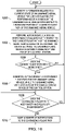
- FIG. 6 an illustration of a process of autonomously operating an unmanned aerial vehicle is depicted in the form of a flowchart in accordance with an illustrative embodiment. The process illustrated in Figure 6 may be used to operate unmanned aerial vehicle 202 from Figures 2-5 .
- the process begins by receiving, by a computer system located onboard an unmanned aerial vehicle, sensor data from a sensor system located onboard the unmanned aerial vehicle (operation 600 ).
- the sensor data is processed, by the computer system, to generate information of interest related to at least one target, while the unmanned aerial vehicle is outside a communications range of a control station (operation 602).
- the computer system then identifies a number of actions to be performed based on the information of interest related to the at least one target and a plurality of rules stored on the computer system (operation 604 ), with the process terminating thereafter.
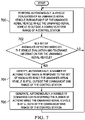
- FIG. 7 an illustration of a process for autonomously detecting a set of anomalies during flight of an unmanned aerial vehicle is depicted in the form of a flowchart in accordance with an illustrative embodiment.
- the process illustrated in Figure 7 may be implemented using, for example, computer system 224 described in Figures 2-5 .
- at least a portion of this process may be implemented using anomaly manager 232 described in Figures 2 , 3 , and 5 .
- the process may begin by autonomously performing a vehicle evaluation of an unmanned aerial vehicle during flight of the unmanned aerial vehicle while the unmanned aerial vehicle is outside communications range of a control station (operation 700 ).
- Operation 700 may be performed by evaluating and processing at least one of data received from a number of vehicle systems onboard the unmanned aerial vehicle, sensor data received from a sensor system onboard the unmanned aerial vehicle, or other types of information.
- the event may be a lapse of a timer, a piece of sensor data receiving a certain value, or some other type of event.
- a number of actions to be taken in response to the set of anomalies is autonomously identified while the unmanned aerial vehicle is still outside the communications range of the control station (operation 704 ).
- a number of commands for performing the number of actions may be autonomously generated while the unmanned aerial vehicle is still outside a communications range of the control station (operation 706 ), with the process then returning to operation 700 as described above.
- the process may immediately return to operation 700 or wait for an event to occur before returning to operation 700 .
- a command for performing an action may only be transmitted to a corresponding system onboard the unmanned aerial vehicle after one or more selected actions have been performed.
- a command may be for performing an action after the unmanned aerial vehicle is back within communications range of the control station.
- a command may be generated for transmitting information of interest about the set of anomalies detected to the control station once the unmanned aerial vehicle is back within communications range of the control station.
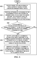
- FIG. 8 an illustration of a process for autonomously performing adaptive sensor control onboard an unmanned aerial vehicle is depicted in the form of a flowchart in accordance with an illustrative embodiment.
- the process illustrated in Figure 8 may be implemented using, for example, computer system 224 described in Figures 2-5 .
- at least a portion of this process may be implemented using adaptive sensor controller 234 described in Figures 2 and 3 .
- the process may begin by receiving imaging data and system data from a number of imaging systems onboard an unmanned aerial vehicle (operation 800 ).
- operation 800 at least a portion of the imaging data and system data may be generated while the unmanned aerial vehicle is outside a communications range of a control station.
- the imaging data may include, for example, without limitation, at least one of electro-optical imaging data, infrared imaging data, radar imaging data, or some other type of imaging data.
- the system data may include, for example, without limitation, at least one of an orientation for an imaging system, a look angle for an imaging system, a focus setting for an imaging system, or some other type of system data.
- an imaging system performance evaluation may be autonomously performed onboard the unmanned aerial vehicle using the imaging data and the system data while the unmanned aerial vehicle is outside a communications range of a control station (operation 802).
- a set of performance parameters may be evaluated for each of the number of imaging systems.
- the set of performance parameters evaluated for one imaging system may be the same or different than the set of performance parameters evaluated for another imaging system.
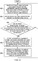
- FIG. 9 an illustration of a process for autonomously managing a mission objective for an unmanned aerial vehicle is depicted in the form of a flowchart in accordance with an illustrative embodiment.
- the process illustrated in Figure 9 may be implemented using, for example, computer system 224 described in Figures 2-5 .
- at least a portion of this process may be implemented using mission manager 236 described in Figures 2 and 5 .
- the process may begin by receiving data from a target detector and a target tracker that are implemented onboard an unmanned aerial vehicle and configured to detect and track, respectively, a number of targets of interest simultaneously (operation 900 ).
- Sensor data may be received from a sensor system onboard the unmanned aerial vehicle (operation 902 ).
- a determination may be made as to whether the target detector and the target tracker are performing as desired based on at least one of the data received from the target detector, the data received from the target tracker, or the sensor data (operation 904 ).
- Operation 904 may be performed while the unmanned aerial vehicle is still outside a communications range of a control station.
- the target detector and the target tracker may be considered operating as desired when the targets being detected and tracked are indeed targets of interest.
- operation 904 may be performed to determine whether the target detector and target tracker are operating with a desired level of accuracy and efficacy.
- the process returns to operation 900 described above. Otherwise, if at least one of the target detector or the target tracker is not performing as desired, a number of actions to be taken in response to at least one of the target detector or the target tracker is not performing as desired are autonomously identified while the unmanned aerial vehicle is outside a communications range of a control station (operation 906 ). A number of commands for performing the number of actions are autonomously generated while the unmanned aerial vehicle is outside the communications range of the control station (operation 908 ), with the process then returning to operation 900 described above.
- FIG. 10 an illustration of a process for autonomously managing a flight path of an unmanned aerial vehicle is depicted in the form of a flowchart in accordance with an illustrative embodiment.
- the process illustrated in Figure 10 may be implemented using, for example, computer system 224 described in Figures 2-5 .
- at least a portion of this process may be implemented using at least one of mission manager 236 described in Figures 2 and 5 , anomaly manager 232 described in Figures 2 , 3 , and 5 , or autonomy interface 238 described in Figures 2 and 5 .
- the process may begin by identifying information related to a current state of an unmanned aerial vehicle for use in evaluating the performance of a mission by the unmanned aerial vehicle with respect to a remaining portion of a current flight path of the unmanned aerial vehicle (operation 1000 ).
- the information identified may include, for example, without limitation, at least one of safety standards information, information about the detection of any anomalies that may affect the safety of the unmanned aerial vehicle, information about the terrain currently below and that will later be below the unmanned aerial vehicle, information about no-fly zones, information about the dynamics of the unmanned aerial vehicle, weather information, information about other aerial vehicles near the current location of the unmanned aerial vehicle, or other types of information.
- a mission performance evaluation may be autonomously performed with respect to the current flight path of the unmanned aerial vehicle based on the information identified, while the unmanned aerial vehicle is outside a communications range of a control station (operation 1002 ).
- a determination may be made as to whether the current flight path needs to be modified (operation 1004 ).
- a contingency flight path is autonomously generated for the unmanned aerial vehicle, while the unmanned aerial vehicle is outside the communications range of the control station (operation 1006 ).
- the contingency flight path may have one or more contingency waypoints that may add to the waypoints of the current flight path, replace one or more waypoints of the current flight path, or both.
- a computer system onboard a primary unmanned aerial vehicle that is outside a communications range of a control station may receive and process data from multiple unmanned aerial vehicles, all of which may also be outside the communications range of the control station.
- the computer system may evaluate operations performed by, performance of, and flight path for each of these multiple unmanned aerial vehicles and determine whether actions need to be command.
- the computer system may autonomously generate and send commands for performing these actions to the various unmanned aerial vehicles while all of the unmanned aerial vehicles are still outside the communications range of the control station.
- a plurality of unmanned aerial vehicles that are outside the communications range of the control station may form a communications network between themselves, which may be used for receiving and transmitting data.
- the plurality of unmanned aerial vehicles may collaboratively work together to autonomously control, manage, and make decisions regarding their collective missions.
- each block in the flowcharts or block diagrams may represent a module, a segment, a function, and/or a portion of an operation or step.
- the function or functions noted in the blocks may occur out of the order noted in the figures.
- two blocks shown in succession may be executed substantially concurrently, or the blocks may sometimes be performed in the reverse order, depending upon the functionality involved.
- other blocks may be added in addition to the illustrated blocks in a flowchart or block diagram.
- Data processing system 1100 may be used to implement computer system 224 in Figure 2 .
- data processing system 1100 includes communications framework 1102, which provides communications between processor unit 1104, storage devices 1106, communications unit 1108, input/output unit 1110, and display 1112.
- communications framework 1102 may be implemented as a bus system.
- Processor unit 1104 is configured to execute instructions for software to perform a number of operations.
- Processor unit 1104 may comprise a number of processors, a multi-processor core, and/or some other type of processor, depending on the implementation.
- processor unit 1104 may take the form of a hardware unit, such as a circuit system, an application specific integrated circuit (ASIC), a programmable logic device, or some other suitable type of hardware unit.
- ASIC application specific integrated circuit
- Storage devices 1106 may be in communication with processor unit 1104 through communications framework 1102.
- a storage device also referred to as a computer readable storage device, is any piece of hardware capable of storing information on a temporary and/or permanent basis. This information may include, but is not limited to, data, program code, and/or other information.
- Memory 1114 and persistent storage 1116 are examples of storage devices 1106.
- Memory 1114 may take the form of, for example, a random access memory or some type of volatile or non-volatile storage device.
- Persistent storage 1116 may comprise any number of components or devices.
- persistent storage 1116 may comprise a hard drive, a flash memory, a rewritable optical disk, a rewritable magnetic tape, or some combination of the above.
- the media used by persistent storage 1116 may or may not be removable.
- Communications unit 1108 allows data processing system 1100 to communicate with other data processing systems and/or devices. Communications unit 1108 may provide communications using physical and/or wireless communications links.
- Input/output unit 1110 allows input to be received from and output to be sent to other devices connected to data processing system 1100.
- input/output unit 1110 may allow user input to be received through a keyboard, a mouse, and/or some other type of input device.
- input/output unit 1110 may allow output to be sent to a printer connected to data processing system 1100.
- Display 1112 is configured to display information to a user.
- Display 1112 may comprise, for example, without limitation, a monitor, a touch screen, a laser display, a holographic display, a virtual display device, and/or some other type of display device.
- processor unit 1104 may perform the processes of the different illustrative embodiments using computer-implemented instructions. These instructions may be referred to as program code, computer usable program code, or computer readable program code and may be read and executed by one or more processors in processor unit 1104.
- program code 1118 is located in a functional form on computer readable media 1120, which is selectively removable, and may be loaded onto or transferred to data processing system 1100 for execution by processor unit 1104.
- Program code 1118 and computer readable media 1120 together form computer program product 1122.
- computer readable media 1120 may be computer readable storage media 1124 or computer readable signal media 1126.
- Computer readable storage media 1124 is a physical or tangible storage device used to store program code 1118 rather than a medium that propagates or transmits program code 1118.
- Computer readable storage media 1124 may be, for example, without limitation, an optical or magnetic disk or a persistent storage device that is connected to data processing system 1100.
- program code 1118 may be transferred to data processing system 1100 using computer readable signal media 1126.
- Computer readable signal media 1126 may be, for example, a propagated data signal containing program code 1118. This data signal may be an electromagnetic signal, an optical signal, and/or some other type of signal that can be transmitted over physical and/or wireless communications links.
- data processing system 1100 in Figure 11 is not meant to provide architectural limitations to the manner in which the illustrative embodiments may be implemented.
- the different illustrative embodiments may be implemented in a data processing system that includes components in addition to or in place of those illustrated for data processing system 1100 . Further, components shown in Figure 11 may be varied from the illustrative examples shown.
Description
- The present disclosure relates generally to unmanned aerial vehicles and, in particular, to autonomously operating unmanned aerial vehicles. Still more particularly, the present disclosure relates to a method and apparatus for autonomously performing decision-making onboard an unmanned aerial vehicle to complete a mission.
- Typically, an unmanned aerial vehicle is operated remotely by a pilot located at a control station. This control station may be located on ground or onboard a different manned aerial vehicle. In some cases, the control station may be located onboard a water vehicle, such as a ship or submarine.
- Unmanned aerial vehicles are used to perform different types of missions, including, but not limited to, intelligence, surveillance, and reconnaissance (ISR) missions. For example, an unmanned aerial vehicle may be remotely operated from a control station and flown into a particular environment. An imaging system attached to the unmanned aerial vehicle may be used to generate raw imaging data for this environment. This raw imaging data is transmitted to the control station for interpretation and analysis by one or more persons at the control station, who then may decide the appropriate course of action. In this manner, perception and interpretation of the environment, as well as decision-making, may be performed by the one or more persons at the control station.
- However, operation of the unmanned aerial vehicle may be constrained by the maximum range for communications between the unmanned aerial vehicle and the control station. As one example, some communications systems onboard an unmanned aerial vehicle may require that the unmanned aerial vehicle be within about 50 miles of the control station. Further, some communications systems onboard an unmanned aerial vehicle may require a direct line of sight between the unmanned aerial vehicle and the control station.
- This communications range requirement for the unmanned aerial vehicle may constrain the types of missions that may be performed by the unmanned aerial vehicle. Therefore, it would be desirable to have a method and apparatus that take into account at least some of the issues discussed above, as well as other possible issues.
-
US 2007/093945 A1 , in accordance with its abstract, describes an unmanned aerial vehicle with a camera and conventional sensors, where the processor navigates the vehicle based at least in part on the image data and the sensor data, and a method for navigating an unmanned aerial vehicle where a processor navigates the vehicle based at least in part on image data corrected by traditional sensor data. -
US 2006/106506 A1 , in accordance with its abstract, describes an autonomous air vehicle comprises a flight control system and an automatic contingency generator for automatically determining a contingent air vehicle route for use by the flight control system in response to contingencies experienced by the air vehicle. A method of automatically determining the contingent air vehicle route is also provided. - According to one aspect, a method is defined by independent claim 1. Further embodiments are defined by dependent claims 2-12.
- According to another aspect, an apparatus is defined by independent claim 13. Further embodiments are defined by dependent claims 14-15.
- The features and functions can be achieved independently in various embodiments of the present disclosure or may be combined in yet other embodiments in which further details can be seen with reference to the following description and drawings.
- The disclosure further comprises the following illustrative, non-exhaustive examples of the above-identified method and apparatus:
The method may further comprise performing, by the computer system autonomously, a mission performance evaluation using at least one of safety standards information, information about a detection of any anomalies that affect safety of the unmanned aerial vehicle, information about terrain, information about no-fly zones, information about dynamics of the unmanned aerial vehicle, weather information, or information about other aerial vehicles near a current location of the unmanned aerial vehicle. - The method may further comprise generating, by the computer system autonomously, a number of commands for performing the number of actions, while the unmanned aerial vehicle is outside the communications range of the control station.
- The apparatus, wherein the computer system may further comprise an anomaly manager that autonomously performs a vehicle evaluation for the unmanned aerial vehicle, identifies a set of anomalies based on the vehicle evaluation, and identifies the number of actions to be performed based on the set of anomalies identified.
- The sensor system of the apparatus may include a number of imaging systems and wherein the computer system may comprise an adaptive sensor controller that autonomously performs an imaging system performance evaluation for the number of imaging systems and identifies the number of actions to be performed based on the imaging system performance evaluation; and
a mission manager that autonomously performs a mission performance evaluation and identifies a contingency flight path for the unmanned aerial vehicle based on the mission performance evaluation. - The features of the claimed subject matter are defined by the independent claims. Further features are defined by the dependent claims. Embodiments and preferred mode of use will be best understood by reference to the following detailed description when read in conjunction with the accompanying drawings.
-
Figure 1 is an illustration of an environment in accordance with an illustrative embodiment; -
Figure 2 is an illustration of an environment in the form of a block diagram in accordance with an illustrative embodiment; -
Figure 3 is an illustration of an anomaly manager of an unmanned aerial vehicle in greater detail in the form of a block diagram in accordance with an illustrative embodiment; -
Figure 4 is an illustration of an adaptive sensor controller of an unmanned aerial vehicle in greater detail in the form of a block diagram in accordance with an illustrative embodiment; -
Figure 5 is an illustration of a mission manager of an unmanned aerial vehicle in greater detail in the form of a block diagram in accordance with an illustrative embodiment; -
Figure 6 is an illustration of a process of autonomously operating an unmanned aerial vehicle in the form of a flowchart in accordance with an illustrative embodiment; -
Figure 7 is an illustration of a process for autonomously detecting a set of anomalies during flight of an unmanned aerial vehicle in the form of a flowchart in accordance with an illustrative embodiment; -
Figure 8 is an illustration of a process for autonomously performing adaptive sensor control onboard an unmanned aerial vehicle in the form of a flowchart in accordance with an illustrative embodiment; -
Figure 9 is an illustration of a process for autonomously managing a mission objective for an unmanned aerial vehicle in the form of a flowchart in accordance with an illustrative embodiment; -
Figure 10 is an illustration of a process for autonomously managing a flight path of an unmanned aerial vehicle in the form of a flowchart in accordance with an illustrative embodiment; and -
Figure 11 is an illustration of a data processing system in the form of a block diagram in accordance with an illustrative embodiment. - The illustrative embodiments recognize and take into account different considerations. For example, the illustrative embodiments recognize and take into account that it may be desirable to have a method for autonomously operating an unmanned aerial vehicle such that decision-making that is traditionally performed by one or more persons at a control station located remotely from the unmanned aerial vehicle may be moved onboard the unmanned aerial vehicle. In particular, the illustrative embodiments recognize and take into account that it may be desirable to autonomously perform interpretation of imaging data and decision-making onboard an unmanned aerial vehicle when the unmanned aerial vehicle is outside a communications range with the control station.
- This type of autonomous operation of the unmanned aerial vehicle may improve reaction times and mission performance. Further, by moving these operations onboard the unmanned aerial vehicle, the burden placed on personnel at the control station may be reduced and cost savings may be achieved.
- The illustrative embodiments also recognize and take into account that the capability of an unmanned aerial vehicle to autonomously operate when outside a communications range may enable the unmanned aerial vehicle to perform tasks in communications-degraded or communications-denied environments. Thus, the illustrative embodiments provide a method and apparatus for autonomously performing decision-making onboard an unmanned aerial vehicle to complete a mission even when the unmanned aerial vehicle is outside a communications range with a control station.
- Referring now to the figures and, in particular, with reference to
Figure 1 , an illustration of an environment is depicted in accordance with an illustrative embodiment. Inenvironment 100, unmannedaerial vehicle 102 may be used to perform a mission. In this illustrative example, unmannedaerial vehicle 102 is performing intelligence, surveillance, and reconnaissance for area ofinterest 104. -
Control station 106 may be located remotely with respect to unmannedaerial vehicle 102. In this illustrative example,control station 106 is atfirst location 108 and unmannedaerial vehicle 102 is atsecond location 110. Unmannedaerial vehicle 102 flies fromcontrol station 106 tosecond location 110 alongflight path 111. -
Second location 110 of unmannedaerial vehicle 102 may beoutside communications range 112 offirst location 108 ofcontrol station 106. In particular, unmannedaerial vehicle 102 may beoutside communications range 112 ofcommunications system 114 atcontrol station 106. However, unmannedaerial vehicle 102 may be configured to autonomously perform processing of data and decision-making based on this processing when outside communications range 112. - With reference now to
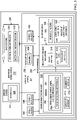
Figure 2 , an illustration of an environment is depicted in the form of a block diagram in accordance with an illustrative embodiment. In this illustrative example,environment 200 includes unmannedaerial vehicle 202.Environment 100 and unmannedaerial vehicle 102 inFigure 1 may be examples of implementations forenvironment 200 and unmannedaerial vehicle 202, respectively. - Unmanned
aerial vehicle 202 is used to performmission 204 with respect to area ofinterest 206. In one illustrative example,mission 204 includes intelligence, surveillance, and reconnaissance (ISR) 208. In some illustrative examples,mission 204 may include performing other types of tasks. - As depicted,
control station 210 may also be present withinenvironment 200.Control station 210 may be located on ground, onboard another aerial vehicle, onboard a water vehicle, onboard a ground vehicle, or on some other type of platform. In this illustrative example,control station 210 takes the form ofground control station 212. - Unmanned
aerial vehicle 202 may fly alongflight path 213 to performmission 204 over area ofinterest 206. For example,control station 210 may be located atfirst location 214. Area ofinterest 206 may be atsecond location 216.Flight path 213 for unmannedaerial vehicle 202 may include flying fromcontrol station 210 to area ofinterest 206 and back tocontrol station 210. - Any number of points along
flight path 213 may be outside a maximum communications range ofcontrol station 210. As one illustrative example,second location 216 of area ofinterest 206 may be outside communications range 218 ofcontrol station 210. Communications range 218 ofcontrol station 210 may be the maximum distance fromcontrol station 210 at which a vehicle, such as unmannedaerial vehicle 202, may communicate withcontrol station 210 to exchange data withcontrol station 210. In some illustrative examples, communications range 218 may be substantially the same at all angles relative to controlstation 210. However, in other illustrative examples, communications range 218 may vary at different angles relative to controlstation 210. In some cases, being outside communications range 218 may also be referred to as being beyond line ofsight 220. - Unmanned
aerial vehicle 202 may be capable of operating autonomously even when unmannedaerial vehicle 202 is outside communications range 218. As depicted, unmannedaerial vehicle 202 may includesensor system 222,computer system 224, anddata storage 226 onboard unmannedaerial vehicle 202.Sensor system 222 generatessensor data 228. In some cases, thissensor data 228 may be stored indata storage 226. -
Data storage 226 may be implemented as part of or separate fromcomputer system 224, depending on the implementation.Data storage 226 may include, for example, without limitation, a number of databases, memory, other types of data structures or storage devices, or some combination thereof. -
Computer system 224processes sensor data 228 to generate information ofinterest 230. In one illustrative example, information ofinterest 230 may be related to at least one target that is of interest. Information ofinterest 230 may be related to at least one target in many different ways. For example, without limitation, information ofinterest 230 may include at least one of information about a target of interest, information related to the search pattern to be used to detect a target of interest, information related to the flight path to be used to detect and track a target of interest, information about how data generated about a target of interest will be communicated to controlstation 210 or another unmanned aerial vehicle or a different type of aerial vehicle, or some other type of information. -
Computer system 224 then identifies number ofactions 225 to be performed based on information ofinterest 230. When information ofinterest 230 is related to at least one target, number ofactions 225 identified may also be related to the at least one target. -
Computer system 224 may processsensor data 228 using decision-makinginformation 231, which may also be stored indata storage 226. Decision-makinginformation 231 may include, for example, without limitation, a plurality of rules, a plurality of instructions, safety requirements, information about no-fly zones, terrain maps, or other types of information. - In some cases, decision-making
information 231 may include a set of preselected options from which number ofactions 225 may be selected. In one illustrative example, the set of preselected options may be received fromcontrol station 210 prior to unmannedaerial vehicle 202 going outside communications range 218 ofcontrol station 210. - At least one of
anomaly manager 232,adaptive sensor controller 234,mission manager 236, andautonomy interface 238 may be implemented oncomputer system 224. As used herein, the phrase "at least one of," when used with a list of items, means different combinations of one or more of the listed items may be used and only one of the items in the list may be needed. The item may be a particular object, thing, step, operation, process, or category. In other words, "at least one of" means any combination of items or number of items may be used from the list, but not all of the items in the list may be required. - For example, without limitation, "at least one of item A, item B, or item C" or "at least one of item A, item B, and item C" may mean item A; item A and item B; item B; item A, item B, and item C; or item B and item C. In some cases, "at least one of item A, item B, or item C" or "at least one of item A, item B, and item C" may mean, but is not limited to, two of item A, one of item B, and ten of item C; four of item B and seven of item C; or some other suitable combination.
- Each of
anomaly manager 232,adaptive sensor controller 234,mission manager 236, andautonomy interface 238 may be implemented oncomputer system 224 and may be implemented using hardware, software, firmware, or a combination thereof. When software is used, operations may be may be implemented using, for example, without limitation, program code configured to run on a processor unit. When firmware is used, the operations performed may be implemented using, for example, without limitation, program code and data and stored in persistent memory to run on a processor unit. - When hardware is employed, the hardware may include one or more circuits that operate to perform operations. Depending on the implementation, the hardware may take the form of a circuit system, an integrated circuit, an application specific integrated circuit (ASIC), a programmable logic device, or some other suitable type of hardware device configured to perform any number of operations.
- A programmable logic device may be configured to perform certain operations. The device may be permanently configured to perform these operations or may be reconfigurable. A programmable logic device may take the form of, for example, without limitation, a programmable logic array, a programmable array logic, a field programmable logic array, a field programmable gate array, or some other type of programmable hardware device.
-
Autonomy interface 238 may be used to check forreliability 240. Depending on the implementation,autonomy interface 238 may be implemented independently or as part ofmission manager 236. - With reference now to
Figure 3 , an illustration ofanomaly manager 232 of unmannedaerial vehicle 202 fromFigure 2 is depicted in greater detail in the form of a block diagram in accordance with an illustrative embodiment. As depicted,anomaly manager 232 may performvehicle evaluation 302 to identify set ofanomalies 304. - As one illustrative example,
anomaly manager 232 may receive data form number ofvehicle systems 306. As used herein, a "number of" items may include one or more items. In this manner, number ofvehicle systems 306 may include one or more vehicle systems. - In this illustrative examples, number of
vehicle systems 306 may include, for example, without limitation, at least one ofhealth management system 308,environmental system 309,navigation system 310,fuel system 311, some other type of vehicle system, or some combination thereof.Anomaly manager 232 receives data from number ofvehicle systems 306 and processes this data to performvehicle evaluation 302. -
Anomaly manager 232 may determine whether any anomalies are present. As used herein, an anomaly may be, for example, an operational or system parameter for unmannedaerial vehicle 202 being outside of selected tolerances. - In one illustrative example,
data structure 312 indata storage 226 may storetolerance information 314 for number ofoperational parameters 316.Tolerance information 314 may include, for example, without limitation, tolerances or thresholds for each of number ofoperational parameters 316. Number ofoperational parameters 316 may include, for example, without limitation, at least one of an altitude, a position, a weight, fuel remaining, a speed, a number of engine parameters, a number of environmental parameters, or some other type of operation parameter. -
Anomaly manager 232 performsvehicle evaluation 302 usingtolerance information 314 to identify any anomalies. When set ofanomalies 304 is identified,anomaly manager 232 then identifies number ofactions 318 to be performed. Number ofactions 318 may include, for example, without limitation, performing set ofadjustments 320 for set ofparameters 322. Set ofparameters 322 may include, but is not limited to,speed 324,altitude 326,position 328, and other types of parameters. In some cases, number ofactions 318 may include stoppingmission 204 and returning to controlstation 210 inFigure 2 . - As one illustrative example,
anomaly manager 232 may detect an engine temperature that is above a maximum threshold as an anomaly and added to set ofanomalies 304 detected.Anomaly manager 232 may identify actions to be taken in response to the high engine temperature, which may include, for example, reducingspeed 324 and reducingaltitude 326. - As another illustrative example, performing
vehicle evaluation 302 may include evaluatingfuel system 311 with respect to fuel quantity and fuel flow rate. For example, without limitation, a fuel reserve that is below a minimum threshold may be detected as an anomaly and added to set ofanomalies 304 detected.Anomaly manager 232 may identify actions to be taken in response to the low fuel reserve, which may include, for example, discontinuing the mission and returning to base. - With reference now to
Figure 4 , an illustration ofadaptive sensor controller 234 of unmannedaerial vehicle 202 fromFigure 2 is depicted in greater detail in the form of a block diagram in accordance with an illustrative embodiment.Adaptive sensor controller 234 may be used to control, for example, without limitation, number ofimaging systems 400 insensor system 222. - Number of
imaging systems 400 may be used to perform, for example, without limitation, target detection. In some cases, number ofimaging systems 400 may also be used to perform target tracking. - Number of
imaging systems 400 may generateimaging data 402 andsystem data 404.Imaging data 402 may include, for example, without limitation, still images, video, or both. Further,imaging data 402 may include, for example, without limitation, at least one of electro-optical imaging data, infrared imaging data, radar imaging data, or some other type of imaging data. -
System data 404 may include data about the operation of number ofimaging systems 400. For example, without limitation,system data 404 may include at least one of an orientation for an imaging system in number ofimaging systems 400, a look angle for an imaging system in number ofimaging systems 400, a focus setting for an imaging system in number ofimaging systems 400, or some other type of system data. -
Adaptive sensor controller 234 may receive andprocess imaging data 402 andsystem data 404 to perform imagingsystem performance evaluation 406. As one illustrative example,adaptive sensor controller 234 may perform imagingsystem performance evaluation 406 by evaluating set ofperformance parameters 408 for each of number ofimaging systems 400. Set ofperformance parameters 408 may include, but are not limited to, at least one of focus setting 410,look angle 412,lighting parameter 414,false detection parameter 416, trackingparameter 418, or some other type of performance parameter. -
Adaptive sensor controller 234 may identify number ofactions 420 to be performed based on imagingsystem performance evaluation 406. Number ofactions 420 may include set ofadjustments 422. Set ofadjustments 422 may include at least one adjustment for at least one performance parameter for at least one of number ofimaging systems 400. In some cases, an adjustment in set ofadjustments 422 may be a zoom change, an aperture setting change, a detection sensitivity change, or some other type of adjustment. - With reference now to
Figure 5 , an illustration ofmission manager 236 of unmannedaerial vehicle 202 fromFigure 2 is depicted in greater detail in the form of a block diagram in accordance with an illustrative embodiment.Mission manager 236 may include, for example, missionobjective manager 500 andflight manager 502. - Mission
objective manager 500 may be used to ensure that unmannedaerial vehicle 202 stays onmission 204. For example, intelligence, surveillance, andreconnaissance 208 may include performing target detection and tracking 504. Target detection and tracking 504 may be performed usingtarget detector 506 andtarget tracker 508.Target detector 506 andtarget tracker 508 may be used to perform target detection and tracking 504 based on, for example,imaging data 402 inFigure 4 . - In some cases, the objective of
mission 204 may be to detect and track a particular target ofinterest 510.Target detector 506 andtarget tracker 508 may perform this detection and tracking, respectively, by processingsensor data 228 using, for example, without limitation, at least one of image edge detection, object recognition, object motion detection, object shape detection, object color recognition, or some other type of detection process, tracking process, or combination thereof. -
Sensor data 228 may be generated bysensor system 222 that may be implemented in many different ways.Sensor system 222 may include, for example, without limitation, at least one of a visible light sensor, an infrared sensor, an electro-optical sensor, a laser, an ultraviolet sensor, a radar system, an ultrasonic imaging system, a sensor system capable of detecting one or more different bandwidths of electromagnetic radiation, a sensor system capable of detecting sound, or some other type of sensor. - Mission
objective manager 500 may monitortarget detector 506 andtarget tracker 508 to ensure that any target that has been detected and is being tracked is indeed target ofinterest 510. In some cases, based on this monitoring, missionobjective manager 500 may identify number ofactions 512 to be performed. An action in number ofactions 512 takes the form of, for example, without limitation, flying unmannedaerial vehicle 202 closer to target ofinterest 510, orbiting around target ofinterest 510, storing information about target ofinterest 510 for future transmission to controlstation 210, or some other type of action. - In some cases, an action in number of
actions 512 includes re-planning at least a portion ofmission 204. For example, without limitation, iftarget detector 506 has been unable to detect target ofinterest 510 for at least a selected period of time, missionobjective manager 500 may generate a new search area, a new search pattern, or some other type of new instruction. -
Flight manager 502 may be used to manageflight path 213 of unmannedaerial vehicle 202. For example, during flight,mission performance evaluation 514 may be performed to monitor performance ofmission 204. Depending on the implementation, missionobjective manager 500,flight manager 502, or both may performmission performance evaluation 514. -
Mission performance evaluation 514 may be based onsearch pattern 516 and plurality ofwaypoints 518 forflight path 213. As one illustrative example,flight manager 502 may usesafety standards information 515 to determine whether thecurrent search pattern 516, plurality ofwaypoints 518, or both are unsafe or will cause undesired anomalies.Flight manager 502 may also use information about the terrain, information about no-fly zones, information about the dynamics of unmannedaerial vehicle 202, and other types of information to evaluatesearch pattern 516 andflight path 213. - In some cases,
flight manager 502 may determine thatcontingency flight path 520 needs to be generated.Flight manager 502 identifies number ofcontingency waypoints 522 forcontingency flight path 520. Number ofcontingency waypoints 522 may replace one or more of plurality ofwaypoints 518 along theoriginal flight path 213. - Depending on the implementation,
flight manager 502 may use information provided by at least one ofanomaly manager 232 orautonomy interface 238 to determine whethercontingency flight path 520 is needed. For example, in response to the detection of a particular type of anomaly byanomaly manager 232,contingency flight path 520 may be needed. As one illustrative example, the detection of a fuel reserve that is below a minimum threshold byanomaly manager 232 may alertflight manager 502 thatcontingency flight path 520 is needed. -
Autonomy interface 238 may be used to ensure that plurality ofwaypoints 518 offlight path 213 and number ofcontingency waypoints 522, if needed, meet selected standards forreliability 240 and safety requirements. As one illustrative example,autonomy interface 238 may monitorflight path 213,contingency flight path 520 if generated, and number ofactions 524 to ensure that waypoints and action commands are generated or updated within a specified time period. If, for example, an update does not fall within the specified time period,autonomy interface 238 may provide one or more contingency waypoints, one or more action commands, or both that are known to be safe and reliable. In this manner, undesired behavior with respect to the generation of and updating of waypoints and action commands may be prevented. In some cases, newly generated or updated waypoints may be monitored to ensure that these waypoints are substantially continuous to within a specified distance interval, meet specified geometric constraints such as turn radius, and are located within specified flight areas. -
Flight manager 502 may also identify number ofactions 524 to be performed. An action in number ofactions 524 may include invokingcontingency flight path 520, orbiting in place, stopping and returning to controlstation 210 inFigure 2 , or some other type of action. - Thus, the various components of
computer system 224 of unmannedaerial vehicle 202, as described inFigures 2-5 , provide the capability for unmannedaerial vehicle 202 to operate autonomously and identify actions to be performed even when unmannedaerial vehicle 202 is outside communications range 218. For example, without limitation,computer system 224 of unmannedaerial vehicle 202 may autonomously generate information ofinterest 230 that is related to at least one target.Computer system 224 may then use a plurality of rules included in decision-makinginformation 231 stored indata storage 226 to identify number ofactions 225 that are to be performed based on information ofinterest 230. Number ofactions 225 may also be considered related to the at least one target. - As one illustrative example,
computer system 224 may process data received from at least one ofsensor system 222, number ofvehicle systems 306,target detector 506, ortarget tracker 508 to identify information ofinterest 230 related to at least one target of interest.Computer system 224 may identify that a target of interest has been detected and that either the sun is to the back of unmannedaerial vehicle 202 or the target is positioned relative to unmannedaerial vehicle 202. Based on a corresponding rule,computer system 224 may then identify actions to be taken, which may include planning and flying a flight path that approaches the target from a new heading and offset distance that may enable the target to be observed and imaged under different lighting conditions. - In another example,
computer system 224 may identify that a target of interest has been detected and the target is suspected of being a mobile target or that the target is moving. Based on another corresponding rule,computer system 224 may identify that unmannedaerial vehicle 202 needs to fly an orbit around the target for a selected period of time to observe any movement of the target or that unmannedaerial vehicle 202 needs to plan and fly a flight path that tracks the moving target for a specified period of time, within a specified area, or both. - In yet another example,
computer system 224 may identify that a target of interest has been detected and that a number of pixels in an image representing the target is less than a selected number. Based on a corresponding rule,computer system 224 may determine that a zoom setting on an imaging system needs to be increased and that unmannedaerial vehicle 202 needs to plan and fly a flight path that keeps the target within the zoomed-in field of view of the imaging system. - Another rule may state that if
computer system 224 detects a target of interest and a contrast of the target within one or more images becomes degraded or the target becomes occluded, then a visible light imaging system that is being used may need to be switched to an infrared imaging system or an imaging system that captures light of a different range of wavelengths. One rule may state that ifcomputer system 224 detects a target that is considered a high-value target and unmannedaerial vehicle 202 is outside communications range 218, then unmannedaerial vehicle 202 may need to transmitimaging data 402 using satellite communications. - In some illustrative examples, a rule may indicate that if
computer system 224 identifies a target that is a noise-sensitive object, then unmannedaerial vehicle 202 may need to plan and fly a flight path that approaches the noise-sensitive object at a lower altitude and with the engine system of unmannedaerial vehicle 202 at a reduced power setting. In one illustrative example, a rule may indicate that if a target of a specified type has been detected, unmannedaerial vehicle 202 is to play and fly multiple flight paths to increase an accuracy of a determination of the location of the target. - In another illustrative example, a rule may state that if a moving target of a specified type is detected, unmanned
aerial vehicle 202 is to decrease a zoom setting on an imaging system such that the environment around the target may be captures. For example, depending on the type of target, it may be desirable to capture roads, trails, buildings, and other types of features in the environment around the target. - In this manner, different types of information of
interest 230 may be autonomously generated by unmannedaerial vehicle 202 even when unmannedaerial vehicle 202 is outside of communications range 218 ofcontrol station 210. Further, different types of rules may be stored onboard unmannedaerial vehicle 202 for use in providing a set of preselected options for identifying actions to be taken based on information ofinterest 230. - Depending on the implementation, unmanned
aerial vehicle 202 subsequently communicates acquired target information and other types of information ofinterest 230 to controlstation 210 once unmannedaerial vehicle 202 is inside or within communications range 218 ofcontrol station 210. In some cases, unmannedaerial vehicle 202 may communicate acquired target information and other types of information ofinterest 230 to other unmanned aerial vehicles while unmannedaerial vehicle 202 is outside of communications range 218. - In this manner, a plurality of unmanned aerial vehicles may be capable of acquiring
sensor data 228 andprocessing sensor data 228 to generate information ofinterest 230 for one target of interest or multiple targets of interest simultaneously even when each of the plurality of unmanned aerial vehicles is outside communications range 218. While a particular unmanned aerial vehicle of the plurality of unmanned aerial vehicles is outside communications range 218, the information ofinterest 230 and other types of information may be stored for future transmission to controlstation 210 once the unmanned aerial vehicles enterscommunications range 218 ofcontrol station 210. In some illustrative examples, a selected unmanned aerial vehicle that is outside communications range 218 ofcontrol station 210 may be able to transmit information ofinterest 230 and other types of information to another unmanned aerial vehicle that is within communications range 218 of both the selected unmanned aerial vehicle and thecontrol station 210. In this manner, a communications relay may be created. - In other illustrative example,
computer system 224 of unmannedaerial vehicle 202 may enable a plurality of unmanned aerial vehicles, such as a swarm of unmanned aerial vehicles, to operate autonomously while the plurality of unmanned aerial vehicles is in a contested airspace or otherwise restricted airspace outside communications range 218 ofcontrol station 210. The plurality of unmanned aerial vehicles may be operated autonomously until the plurality of unmanned aerial vehicles flies within communications range 218 ofcontrol station 210. In this manner, the range of control, processing, decision-making, and communications provided bycontrol station 210 for a plurality of autonomous vehicles may be extended beyond the range ofcontrol station 210 such that one or more targets of interest in one or more search contested or otherwise restricted areas of interest may be tracked simultaneously. - In particular,
computer system 224 enables unmannedaerial vehicle 202 to perform on-vehicle decision-making for responding to system anomalies, on-vehicle adaptive control of sensors to obtain more reliable and higher quality information, on-vehicle interpretation of sensor data to discern actionable information, on-board reasoning and flight guidance to extend range of operation, and on-vehicle verification of guidance waypoints to assure safety. - The illustrations of unmanned
aerial vehicle 202 inFigures 2-5 are not meant to imply physical or architectural limitations to the manner in which an illustrative embodiment may be implemented. Other components in addition to or in place of the ones illustrated may be used. Some components may be optional. Also, the blocks are presented to illustrate some functional components. One or more of these blocks may be combined, divided, or combined and divided into different blocks when implemented in an illustrative embodiment. - In some cases,
target detector 506 andtarget tracker 508 may be implemented together as a target detector and tracker. In other illustrative examples,anomaly manager 232 may be implemented withinmission manager 236. - With reference now to
Figure 6 , an illustration of a process of autonomously operating an unmanned aerial vehicle is depicted in the form of a flowchart in accordance with an illustrative embodiment. The process illustrated inFigure 6 may be used to operate unmannedaerial vehicle 202 fromFigures 2-5 . - The process begins by receiving, by a computer system located onboard an unmanned aerial vehicle, sensor data from a sensor system located onboard the unmanned aerial vehicle (operation 600). The sensor data is processed, by the computer system, to generate information of interest related to at least one target, while the unmanned aerial vehicle is outside a communications range of a control station (operation 602). The computer system then identifies a number of actions to be performed based on the information of interest related to the at least one target and a plurality of rules stored on the computer system (operation 604), with the process terminating thereafter.
- With reference now to
Figure 7 , an illustration of a process for autonomously detecting a set of anomalies during flight of an unmanned aerial vehicle is depicted in the form of a flowchart in accordance with an illustrative embodiment. The process illustrated inFigure 7 may be implemented using, for example,computer system 224 described inFigures 2-5 . In particular, at least a portion of this process may be implemented usinganomaly manager 232 described inFigures 2 ,3 , and5 . - The process may begin by autonomously performing a vehicle evaluation of an unmanned aerial vehicle during flight of the unmanned aerial vehicle while the unmanned aerial vehicle is outside communications range of a control station (operation 700).
Operation 700 may be performed by evaluating and processing at least one of data received from a number of vehicle systems onboard the unmanned aerial vehicle, sensor data received from a sensor system onboard the unmanned aerial vehicle, or other types of information. - A determination may be made as to whether a set of anomalies is detected based on the vehicle evaluation and tolerance information for the unmanned aerial vehicle (operation 702). If no anomalies are detected, the process returns to
operation 700 described above. In some cases, the process may wait for an event to occur before returning tooperation 700. For example, the event may be a lapse of a timer, a piece of sensor data receiving a certain value, or some other type of event. - With reference again to
operation 702, if a set of anomalies is detected, a number of actions to be taken in response to the set of anomalies is autonomously identified while the unmanned aerial vehicle is still outside the communications range of the control station (operation 704). A number of commands for performing the number of actions may be autonomously generated while the unmanned aerial vehicle is still outside a communications range of the control station (operation 706), with the process then returning tooperation 700 as described above. Depending on the implementation, the process may immediately return tooperation 700 or wait for an event to occur before returning tooperation 700. - In some cases, a command for performing an action may only be transmitted to a corresponding system onboard the unmanned aerial vehicle after one or more selected actions have been performed. Depending on the implementation, a command may be for performing an action after the unmanned aerial vehicle is back within communications range of the control station. For example, a command may be generated for transmitting information of interest about the set of anomalies detected to the control station once the unmanned aerial vehicle is back within communications range of the control station.
- With reference now to
Figure 8 , an illustration of a process for autonomously performing adaptive sensor control onboard an unmanned aerial vehicle is depicted in the form of a flowchart in accordance with an illustrative embodiment. The process illustrated inFigure 8 may be implemented using, for example,computer system 224 described inFigures 2-5 . In particular, at least a portion of this process may be implemented usingadaptive sensor controller 234 described inFigures 2 and3 . - The process may begin by receiving imaging data and system data from a number of imaging systems onboard an unmanned aerial vehicle (operation 800). In
operation 800, at least a portion of the imaging data and system data may be generated while the unmanned aerial vehicle is outside a communications range of a control station. The imaging data may include, for example, without limitation, at least one of electro-optical imaging data, infrared imaging data, radar imaging data, or some other type of imaging data. The system data may include, for example, without limitation, at least one of an orientation for an imaging system, a look angle for an imaging system, a focus setting for an imaging system, or some other type of system data. - Next, an imaging system performance evaluation may be autonomously performed onboard the unmanned aerial vehicle using the imaging data and the system data while the unmanned aerial vehicle is outside a communications range of a control station (operation 802). In operation 802, a set of performance parameters may be evaluated for each of the number of imaging systems. The set of performance parameters evaluated for one imaging system may be the same or different than the set of performance parameters evaluated for another imaging system.
- A determination may then be made as to whether the number of imaging systems is performing as desired with respect to a set of performance parameters for each of the number of imaging systems (operation 804). If the number of imaging systems is performing as desired, the process returns to
operation 800 described above. Otherwise, a number of actions to be taken in response to the number of imaging systems not performing as desired are autonomously identified while the unmanned aerial vehicle is still outside the communications range of the control station (operation 806). A number of commands for performing the number of actions are autonomously generated, while the unmanned aerial vehicle is still outside communications range of the control station (operation 808), with the process then returning tooperation 800 described above. - With reference now to
Figure 9 , an illustration of a process for autonomously managing a mission objective for an unmanned aerial vehicle is depicted in the form of a flowchart in accordance with an illustrative embodiment. The process illustrated inFigure 9 may be implemented using, for example,computer system 224 described inFigures 2-5 . In particular, at least a portion of this process may be implemented usingmission manager 236 described inFigures 2 and5 . - The process may begin by receiving data from a target detector and a target tracker that are implemented onboard an unmanned aerial vehicle and configured to detect and track, respectively, a number of targets of interest simultaneously (operation 900). Sensor data may be received from a sensor system onboard the unmanned aerial vehicle (operation 902). A determination may be made as to whether the target detector and the target tracker are performing as desired based on at least one of the data received from the target detector, the data received from the target tracker, or the sensor data (operation 904).
Operation 904 may be performed while the unmanned aerial vehicle is still outside a communications range of a control station. - For example, without limitation, in
operation 904, the target detector and the target tracker may be considered operating as desired when the targets being detected and tracked are indeed targets of interest. In other words,operation 904 may be performed to determine whether the target detector and target tracker are operating with a desired level of accuracy and efficacy. - With reference to
operation 904, if the target detector and the target tracker are performing as desired, the process returns tooperation 900 described above. Otherwise, if at least one of the target detector or the target tracker is not performing as desired, a number of actions to be taken in response to at least one of the target detector or the target tracker is not performing as desired are autonomously identified while the unmanned aerial vehicle is outside a communications range of a control station (operation 906). A number of commands for performing the number of actions are autonomously generated while the unmanned aerial vehicle is outside the communications range of the control station (operation 908), with the process then returning tooperation 900 described above. - With reference now to
Figure 10 , an illustration of a process for autonomously managing a flight path of an unmanned aerial vehicle is depicted in the form of a flowchart in accordance with an illustrative embodiment. The process illustrated inFigure 10 may be implemented using, for example,computer system 224 described inFigures 2-5 . In particular, at least a portion of this process may be implemented using at least one ofmission manager 236 described inFigures 2 and5 ,anomaly manager 232 described inFigures 2 ,3 , and5 , orautonomy interface 238 described inFigures 2 and5 . - The process may begin by identifying information related to a current state of an unmanned aerial vehicle for use in evaluating the performance of a mission by the unmanned aerial vehicle with respect to a remaining portion of a current flight path of the unmanned aerial vehicle (operation 1000). In
operation 1000, the information identified may include, for example, without limitation, at least one of safety standards information, information about the detection of any anomalies that may affect the safety of the unmanned aerial vehicle, information about the terrain currently below and that will later be below the unmanned aerial vehicle, information about no-fly zones, information about the dynamics of the unmanned aerial vehicle, weather information, information about other aerial vehicles near the current location of the unmanned aerial vehicle, or other types of information. - Next, a mission performance evaluation may be autonomously performed with respect to the current flight path of the unmanned aerial vehicle based on the information identified, while the unmanned aerial vehicle is outside a communications range of a control station (operation 1002). A determination may be made as to whether the current flight path needs to be modified (operation 1004).
- If the current flight path does not need to be modified, the process returns to
operation 1000 described above. Otherwise, if the current flight path needs to be modified, a contingency flight path is autonomously generated for the unmanned aerial vehicle, while the unmanned aerial vehicle is outside the communications range of the control station (operation 1006). Inoperation 1006, the contingency flight path may have one or more contingency waypoints that may add to the waypoints of the current flight path, replace one or more waypoints of the current flight path, or both. - Next, a determination may be made as to whether the contingency flight path meets safety and reliability requirements (operation 1008). If the contingency flight path does not meet safety and reliability requirements, a number of modifications are made to the contingency flight path (operation 1010), with the process returning to
operation 1008 described above. Otherwise, if the contingency flight path does meet safety and reliability requirements, the process returns tooperation 1000 described above. - While the processes described in
Figures 6-10 are described with respect to a single unmanned aerial vehicle, these processes may be performed for a plurality of unmanned aerial vehicles. As one illustrative example, a computer system onboard a primary unmanned aerial vehicle that is outside a communications range of a control station may receive and process data from multiple unmanned aerial vehicles, all of which may also be outside the communications range of the control station. The computer system may evaluate operations performed by, performance of, and flight path for each of these multiple unmanned aerial vehicles and determine whether actions need to be command. The computer system may autonomously generate and send commands for performing these actions to the various unmanned aerial vehicles while all of the unmanned aerial vehicles are still outside the communications range of the control station. - In this manner, the control, management, and decision-making that would typically be performed at a control station may be extended beyond the communications range of the control station using the primary unmanned aerial vehicle. In some illustrative examples, a plurality of unmanned aerial vehicles that are outside the communications range of the control station may form a communications network between themselves, which may be used for receiving and transmitting data. In this manner, the plurality of unmanned aerial vehicles may collaboratively work together to autonomously control, manage, and make decisions regarding their collective missions.
- The flowcharts and block diagrams in the different depicted embodiments illustrate the architecture, functionality, and operation of some possible implementations of apparatuses and methods in an illustrative embodiment. In this regard, each block in the flowcharts or block diagrams may represent a module, a segment, a function, and/or a portion of an operation or step.
- In some alternative implementations of an illustrative embodiment, the function or functions noted in the blocks may occur out of the order noted in the figures. For example, in some cases, two blocks shown in succession may be executed substantially concurrently, or the blocks may sometimes be performed in the reverse order, depending upon the functionality involved. Also, other blocks may be added in addition to the illustrated blocks in a flowchart or block diagram.
- Turning now to
Figure 11 , an illustration of a data processing system is depicted in the form of a block diagram in accordance with an illustrative embodiment.Data processing system 1100 may be used to implementcomputer system 224 inFigure 2 . As depicted,data processing system 1100 includescommunications framework 1102, which provides communications betweenprocessor unit 1104,storage devices 1106,communications unit 1108, input/output unit 1110, anddisplay 1112. In some cases,communications framework 1102 may be implemented as a bus system. -
Processor unit 1104 is configured to execute instructions for software to perform a number of operations.Processor unit 1104 may comprise a number of processors, a multi-processor core, and/or some other type of processor, depending on the implementation. In some cases,processor unit 1104 may take the form of a hardware unit, such as a circuit system, an application specific integrated circuit (ASIC), a programmable logic device, or some other suitable type of hardware unit. - Instructions for the operating system, applications, and/or programs run by
processor unit 1104 may be located instorage devices 1106.Storage devices 1106 may be in communication withprocessor unit 1104 throughcommunications framework 1102. As used herein, a storage device, also referred to as a computer readable storage device, is any piece of hardware capable of storing information on a temporary and/or permanent basis. This information may include, but is not limited to, data, program code, and/or other information. -
Memory 1114 andpersistent storage 1116 are examples ofstorage devices 1106.Memory 1114 may take the form of, for example, a random access memory or some type of volatile or non-volatile storage device.Persistent storage 1116 may comprise any number of components or devices. For example,persistent storage 1116 may comprise a hard drive, a flash memory, a rewritable optical disk, a rewritable magnetic tape, or some combination of the above. The media used bypersistent storage 1116 may or may not be removable. -
Communications unit 1108 allowsdata processing system 1100 to communicate with other data processing systems and/or devices.Communications unit 1108 may provide communications using physical and/or wireless communications links. - Input/
output unit 1110 allows input to be received from and output to be sent to other devices connected todata processing system 1100. For example, input/output unit 1110 may allow user input to be received through a keyboard, a mouse, and/or some other type of input device. As another example, input/output unit 1110 may allow output to be sent to a printer connected todata processing system 1100. -
Display 1112 is configured to display information to a user.Display 1112 may comprise, for example, without limitation, a monitor, a touch screen, a laser display, a holographic display, a virtual display device, and/or some other type of display device. - In this illustrative example, the processes of the different illustrative embodiments may be performed by
processor unit 1104 using computer-implemented instructions. These instructions may be referred to as program code, computer usable program code, or computer readable program code and may be read and executed by one or more processors inprocessor unit 1104. - In these examples,
program code 1118 is located in a functional form on computerreadable media 1120, which is selectively removable, and may be loaded onto or transferred todata processing system 1100 for execution byprocessor unit 1104.Program code 1118 and computerreadable media 1120 together formcomputer program product 1122. In this illustrative example, computerreadable media 1120 may be computerreadable storage media 1124 or computerreadable signal media 1126. - Computer
readable storage media 1124 is a physical or tangible storage device used to storeprogram code 1118 rather than a medium that propagates or transmitsprogram code 1118. Computerreadable storage media 1124 may be, for example, without limitation, an optical or magnetic disk or a persistent storage device that is connected todata processing system 1100. - Alternatively,
program code 1118 may be transferred todata processing system 1100 using computerreadable signal media 1126. Computerreadable signal media 1126 may be, for example, a propagated data signal containingprogram code 1118. This data signal may be an electromagnetic signal, an optical signal, and/or some other type of signal that can be transmitted over physical and/or wireless communications links. - The illustration of
data processing system 1100 inFigure 11 is not meant to provide architectural limitations to the manner in which the illustrative embodiments may be implemented. The different illustrative embodiments may be implemented in a data processing system that includes components in addition to or in place of those illustrated fordata processing system 1100. Further, components shown inFigure 11 may be varied from the illustrative examples shown.
Claims (15)
- A method comprising:flying an unmanned aerial vehicle (202) along a flight path (213) from a control station (210) at a first location (214) to an area of interest (206) at a second location (216) and back to the control station (210), wherein the second location (216) may be outside a communication range (218) of the control station (210);receiving (600), by a computer system (224) located onboard the unmanned aerial vehicle (202), sensor data (228) generated by sensors located onboard the unmanned aerial vehicle (202);processing (602), by the computer system (224), the sensor data (228) using at least one of image edge detection, object recognition, object motion detection, and object shape detection to autonomously generate information of interest (230) related to at least one target, while the unmanned aerial vehicle (202) is outside the communications range (218) of the control station (210), wherein said autonomously generated information of interest (230) includes:- information about the at least one target;- information related to a search pattern to be used to detect the at least one target;- information related to a flight path to be used to detect and track the at least one target;- information about how data generated about the at least one target will be communicated to the control station (210); andidentifying (604), by the computer system (224) autonomously, a number of actions (225) to be performed based on the information of interest (230) related to the at least one target, while the unmanned aerial vehicle (202) is outside the communications range (218) of the control station (210), wherein the number of actions include:- flying the unmanned aerial vehicle (202) closer to the at least one target and storing information about the at least one target for future transmission to the control station (210);- re-planning at least a portion of the flight path to generate a new search area or a new search pattern when at least one target is unable to be detectable for at least a selected period of time; and- communicating the information about the at least one target to the control station (210) when the unmanned aerial vehicle (202) is within the communications range (218) of the control station (210) .
- The method of claim 1, wherein processing (602) the sensor data (228) comprises:
performing, by the computer system (224) autonomously, an evaluation using the sensor data (228), wherein the sensor data (228) includes imaging data (402) generated by the number of imaging systems (400). - The method of claim 2, wherein identifying (604) the number of actions (225) comprises:
identifying, by the computer system (224) autonomously, the number of actions (225,512) to be performed based on the sensor data (228) that includes imaging data (402). - The method of claim 1, wherein processing (602) the sensor data (228) comprises:
performing, by the computer system (224) autonomously, a vehicle evaluation (302) for the unmanned aerial vehicle (202) using the sensor data (228), data received from a number of vehicle systems (306) onboard the unmanned aerial vehicle (202), and tolerance information for a number of operational parameters for the unmanned aerial vehicle (202), while the unmanned aerial vehicle (202) is outside the communications range (218) of the control station (210). - The method of claim 4, wherein processing (602) the sensor data (228) further comprises:
detecting, by the computer system (224) autonomously, a set of anomalies (304) based on the vehicle evaluation (302), while the unmanned aerial vehicle (202) is outside the communications range (218) of the control station (210). - The method of claim 5, wherein identifying the number of actions (225) comprises:
identifying, by the computer system (224) autonomously, the number of actions (225) to be performed based on the set of anomalies (304) detected, while the unmanned aerial vehicle (202) is outside the communications range (218) of the control station (210). - The method of any of claims 1 through 3, wherein identifying the number of actions (225) comprises:
identifying, by the computer system (224) autonomously, the number of actions (225, 512) to be performed based on the information of interest (230) related to the at least one target, wherein the information of interest includes information related to tracking the at least one target and the number of actions (225, 512) includes storing information about the at least one target for future transmission to control station (210), while the unmanned aerial vehicle (202) is in a restricted airspace outside the communications range (218) of the control station (210). - The method of claim 1 further comprising:
receiving (600) from the control station (210), prior to the unmanned aerial vehicle (202) going outside the communications range (218) of the control station (210), a set of preselected options from which at least one of the number of actions (225) is to be selected. - The method of claim 1, wherein processing (602) the sensor data (228) comprises:
performing, by the computer system (224) autonomously, a mission performance evaluation (514) for the unmanned aerial vehicle (202) with respect to the flight path (213) of the unmanned aerial vehicle (202). - The method of claim 9, wherein identifying the number of actions (225) comprises:determining, by the computer system (224) autonomously, whether a contingency flight path (520) is needed based on the mission performance evaluation (514); andgenerating, by the computer system (224) autonomously, the contingency flight path (520), while the unmanned aerial vehicle (202) is outside communications range (218) of the control station (210).
- The method of claim 1, further comprising:identifying, by the computer system (224) located onboard the unmanned aerial vehicle (202), information related to at least one target, wherein the information is based on data that is received from at least one of a sensor system (222), a target detector (506), a target tracker (508), or a number of vehicle systems (306) implemented onboard the unmanned aerial vehicle (202);evaluating, by the computer system (224) autonomously, the operation of the unmanned aerial vehicle (202) and a performance of a mission of the unmanned aerial vehicle (202) using the information, while the unmanned aerial vehicle (202) is outside the communications range (218) of the control station (210); andidentifying, by the computer system (224) autonomously, the number of actions (225) to be performed based on evaluation of the operation of and the performance of the mission of the unmanned aerial vehicle (202), while the unmanned aerial vehicle (202) is outside the communications range (218) of the control station (210).
- The method of claim 7 further comprising:
transmitting, by the computer system (224) autonomously, at least one of the information stored about the at least one target or information of interest (230) including information related to tracking the at least one target to the control station (210), when the unmanned aerial enters within the communications range (218) of the control station (210), wherein the unmanned aerial vehicle (202) is extended beyond the range of control station (210) such that at least one target in a restricted airspace may be tracked. - An apparatus comprising:an unmanned aerial vehicle (202) configured to follow a flight path (213) to perform a mission over an area of interest (206), where the flight path (213) includes flying from a control station (210) at a first location (214) to the area of interest (206) at a second location (216) and back to the control station (210),a sensor system (222) that is located onboard the unmanned aerial vehicle (202) and that generates sensor data (228); anda computer system (224) that is located onboard the unmanned aerial vehicle (202) and that receives the sensor data (228), processes the sensor data (228) using at least one of image edge detection, object recognition, object motion detection, and object shape detection to autonomously generate information of interest (230) related to at least one target, wherein said information of interest (230) includes:- information about the at least one target;- information related to a search pattern to be used to detect the at least one target;- information related to a flight path to be used to detect and track the at least one target;- information about how data generated about the at least one target will be communicated to the control station (210),wherein the computer system (224) is configured to identify a number of actions (225) to be performed based on the information of interest (230) related to the at least one target, while the unmanned aerial vehicle (202) is located outside a communications range (218) of the control station (210),wherein the number of actions (225) includes:- flying the unmanned aerial vehicle (202) closer to the at least one target and storing the information of interest (230) for future transmission to the control station (210), and- re-planning at least a portion of the flight path to generate a new search area or a new search pattern when at least one target is unable to be detectable for at least a selected period of time,wherein the computer system (224) is configured to communicate the information of interest (230) to the control station (210) once the unmanned aerial vehicle (202) is within the communications range (218) of the control station (210).
- The apparatus of claim 13, wherein the computer system (224) is configured to autonomously process the sensor data (228) and identify the number of actions (225, 512) to be performed autonomously, the number of actions (212, 512) to be performed including storing information about the at least one target for future transmission to control station (210), while the unmanned aerial vehicle (202) is located in a restricted airspace outside the communications range (218) of the control station (210).
- The apparatus of claim 14, wherein the computer system (224) further comprises:
a communication network that transmits to the control station (210), one of the information stored about the at least one target or information of interest (230) that includes information related to tracking the at least one target, when the unmanned aerial enters within the communications range (218) of the control station (210), wherein the unmanned aerial vehicle (202) is extended beyond the range of control station (210) such that at least one target in a restricted airspace may be tracked.
Applications Claiming Priority (1)
| Application Number | Priority Date | Filing Date | Title |
|---|---|---|---|
| US14/732,409 US9715235B2 (en) | 2015-06-05 | 2015-06-05 | Autonomous unmanned aerial vehicle decision-making |
Publications (3)
| Publication Number | Publication Date |
|---|---|
| EP3101502A2 EP3101502A2 (en) | 2016-12-07 |
| EP3101502A3 EP3101502A3 (en) | 2017-01-25 |
| EP3101502B1 true EP3101502B1 (en) | 2022-06-01 |
Family
ID=55628744
Family Applications (1)
| Application Number | Title | Priority Date | Filing Date |
|---|---|---|---|
| EP16160403.8A Active EP3101502B1 (en) | 2015-06-05 | 2016-03-15 | Autonomous unmanned aerial vehicle decision-making |
Country Status (3)
| Country | Link |
|---|---|
| US (1) | US9715235B2 (en) |
| EP (1) | EP3101502B1 (en) |
| CN (1) | CN106249750B (en) |
Families Citing this family (40)
| Publication number | Priority date | Publication date | Assignee | Title |
|---|---|---|---|---|
| JP6274036B2 (en) * | 2014-07-01 | 2018-02-07 | 株式会社デンソー | Control device |
| US9689976B2 (en) | 2014-12-19 | 2017-06-27 | Xidrone Systems, Inc. | Deterent for unmanned aerial systems |
| US9715009B1 (en) | 2014-12-19 | 2017-07-25 | Xidrone Systems, Inc. | Deterent for unmanned aerial systems |
| CN112908042A (en) | 2015-03-31 | 2021-06-04 | 深圳市大疆创新科技有限公司 | System and remote control for operating an unmanned aerial vehicle |
| WO2016154943A1 (en) | 2015-03-31 | 2016-10-06 | SZ DJI Technology Co., Ltd. | Systems and methods for geo-fencing device communications |
| US10364026B1 (en) * | 2015-09-21 | 2019-07-30 | Amazon Technologies, Inc. | Track and tether vehicle position estimation |
| KR102054089B1 (en) | 2015-09-28 | 2019-12-09 | 디파트먼트 13, 인코포레이티드 | Drone Intrusion Detection and Response Measures |
| US10008123B2 (en) * | 2015-10-20 | 2018-06-26 | Skycatch, Inc. | Generating a mission plan for capturing aerial images with an unmanned aerial vehicle |
| CN105278544B (en) * | 2015-10-30 | 2018-05-08 | 小米科技有限责任公司 | The control method and device of unmanned vehicle |
| US10609901B2 (en) * | 2016-02-19 | 2020-04-07 | International Business Machines Corporation | Unmanned aerial vehicle for generating geolocation exclusion zones |
| US11134380B2 (en) | 2016-10-11 | 2021-09-28 | Whitefox Defense Technologies, Inc. | Systems and methods for cyber-physical vehicle management, detection and control |
| AU2017342017A1 (en) | 2016-10-11 | 2019-05-02 | Whitefox Defense Technologies, Inc. | Systems and methods for cyber-physical vehicle management, detection and control |
| JP6688901B2 (en) * | 2016-10-17 | 2020-04-28 | エスゼット ディージェイアイ テクノロジー カンパニー リミテッドSz Dji Technology Co.,Ltd | Three-dimensional shape estimation method, three-dimensional shape estimation system, flying object, program, and recording medium |
| US10531994B2 (en) | 2017-01-30 | 2020-01-14 | SkyRyse, Inc. | Safety system for aerial vehicles and method of operation |
| US9849044B1 (en) | 2017-01-30 | 2017-12-26 | SkyRyse, Inc. | Vehicle system and method for providing services |
| JP6944790B2 (en) * | 2017-02-22 | 2021-10-06 | 株式会社トプコン | Controls, optics, control methods, unmanned aerial vehicle tracking systems and programs |
| US10317904B2 (en) * | 2017-05-05 | 2019-06-11 | Pinnacle Vista, LLC | Underwater leading drone system |
| WO2019023322A1 (en) | 2017-07-27 | 2019-01-31 | SkyRyse, Inc. | System and method for situational awareness, vehicle control, and/or contingency planning |
| CN109426275B (en) * | 2017-09-01 | 2021-08-06 | 昊翔电能运动科技(昆山)有限公司 | Virtual no-fly zone setting and flight control method and device based on virtual no-fly zone |
| US11032022B1 (en) | 2017-10-11 | 2021-06-08 | Genghiscomm Holdings, LLC | Detection, analysis, and countermeasures for automated and remote-controlled devices |
| US11059378B2 (en) * | 2017-11-16 | 2021-07-13 | The Boeing Company | Charging a rechargeable battery of an unmanned aerial vehicle in flight using a high voltage power line |
| US11079757B1 (en) * | 2017-11-20 | 2021-08-03 | Amazon Technologies, Inc. | Unmanned aerial vehicles to survey locations and collect data about different signal sources |
| MA41572B1 (en) | 2017-12-05 | 2019-08-30 | Atlan Space | Autonomous navigation and behavior of unmanned vehicle without connection to the control station |
| US10907940B1 (en) | 2017-12-12 | 2021-02-02 | Xidrone Systems, Inc. | Deterrent for unmanned aerial systems using data mining and/or machine learning for improved target detection and classification |
| US10769466B2 (en) * | 2018-02-20 | 2020-09-08 | International Business Machines Corporation | Precision aware drone-based object mapping based on spatial pattern recognition |
| US10866597B1 (en) * | 2018-05-07 | 2020-12-15 | Securus Technologies, Llc | Drone detection and interception |
| EP3804395A1 (en) * | 2018-06-04 | 2021-04-14 | Telefonaktiebolaget LM Ericsson (publ) | Flight path plan availability indication |
| CA3106457A1 (en) * | 2018-07-17 | 2020-01-23 | Emesent IP Pty Ltd | Method for exploration and mapping using an aerial vehicle |
| CN110832419A (en) * | 2018-07-25 | 2020-02-21 | 深圳市大疆创新科技有限公司 | Unmanned aerial vehicle control method and system and unmanned aerial vehicle |
| WO2020051226A1 (en) | 2018-09-05 | 2020-03-12 | Whitefox Defense Technologies, Inc. | Integrated secure device manager systems and methods for cyber-physical vehicles |
| US20200158822A1 (en) * | 2018-09-06 | 2020-05-21 | Airspace Systems, Inc. | Unmanned aerial vehicle radar detection |
| WO2020086499A1 (en) * | 2018-10-22 | 2020-04-30 | Seekops Inc. | A uav-borne, high-bandwidth, lightweight point sensor for quantifying greenhouse gases in atmospheric strata |
| CN110664417A (en) * | 2019-09-18 | 2020-01-10 | 朔黄铁路发展有限责任公司 | Train safe driving early warning equipment and system |
| CN111754357A (en) * | 2019-10-28 | 2020-10-09 | 广州极飞科技有限公司 | Job control method, device, system, equipment and readable storage medium |
| US11345473B1 (en) | 2019-12-05 | 2022-05-31 | Rockwell Collins, Inc. | System and method for preventing inadvertent loss of surveillance coverage for an unmanned aerial system (UAS) |
| US11705009B2 (en) | 2019-12-05 | 2023-07-18 | Rockwell Collins, Inc. | System and method for optimizing mission fulfillment by unmanned aircraft systems (UAS) via dynamic atmospheric modeling |
| US11423789B2 (en) | 2019-12-05 | 2022-08-23 | Rockwell Collins, Inc. | System and method for preventing inadvertent loss of command and control link to an unmanned aerial system |
| CN112198887B (en) * | 2019-12-31 | 2022-04-01 | 北京理工大学 | Multi-rotor unmanned aerial vehicle onboard computer performance evaluation system method |
| EP3940672A1 (en) * | 2020-07-15 | 2022-01-19 | Advanced Laboratory on Embedded Systems S.r.l. | Assurance module |
| EP4107988A4 (en) * | 2021-04-23 | 2023-11-22 | ZTE Corporation | Method, device and computer program product for wireless communication |
Family Cites Families (17)
| Publication number | Priority date | Publication date | Assignee | Title |
|---|---|---|---|---|
| US20030164794A1 (en) * | 2002-03-04 | 2003-09-04 | Time Domain Corporation | Over the horizon communications network and method |
| US7127334B2 (en) * | 2002-12-03 | 2006-10-24 | Frink Bentley D | System and methods for preventing the unauthorized use of aircraft |
| US7512462B2 (en) | 2004-11-16 | 2009-03-31 | Northrop Grumman Corporation | Automatic contingency generator |
| US8078319B2 (en) | 2005-02-16 | 2011-12-13 | Lockheed Martin Corporation | Hierarchical contingency management system for mission planners |
| US8855846B2 (en) * | 2005-10-20 | 2014-10-07 | Jason W. Grzywna | System and method for onboard vision processing |
| US9026272B2 (en) * | 2007-12-14 | 2015-05-05 | The Boeing Company | Methods for autonomous tracking and surveillance |
| CN101592955A (en) * | 2009-04-08 | 2009-12-02 | 孙卓 | A kind of full-automatic unmanned aerial vehicle control system |
| US8463459B2 (en) * | 2010-08-24 | 2013-06-11 | The Boeing Company | Methods and apparatus for indicating a location |
| EP2645196B1 (en) | 2012-03-30 | 2018-12-12 | The Boeing Company | Network of unmanned vehicles |
| US9552503B2 (en) * | 2012-05-01 | 2017-01-24 | 5D Robotics, Inc. | Distributed positioning and collaborative behavior determination |
| DE102012104783B4 (en) * | 2012-06-01 | 2019-12-24 | Quantum-Systems Gmbh | Aircraft, preferably UAV, drone and / or UAS |
| CN102802140A (en) * | 2012-08-22 | 2012-11-28 | 上海德芯信息科技有限公司 | Self-organizing emergency communication network system and communication method |
| EP2733560A1 (en) | 2012-11-19 | 2014-05-21 | The Boeing Company | Autonomous mission management |
| CN103149893B (en) * | 2013-01-29 | 2016-08-03 | 中国人民解放军装备学院 | Motor-driven self-organization situation monitoring system |
| US9688403B2 (en) * | 2014-05-20 | 2017-06-27 | Infatics, Inc. | Method for adaptive mission execution on an unmanned aerial vehicle |
| CN104503456B (en) * | 2014-11-25 | 2017-06-30 | 湖南基石信息技术有限公司 | Unmanned aerial vehicle (UAV) control apparatus and method based on 4G communications |
| CN104517432A (en) * | 2014-12-24 | 2015-04-15 | 兰州大学 | Monitoring system based on unmanned aerial vehicle and wireless sensor network |
-
2015
- 2015-06-05 US US14/732,409 patent/US9715235B2/en active Active
-
2016
- 2016-03-15 EP EP16160403.8A patent/EP3101502B1/en active Active
- 2016-06-02 CN CN201610384341.2A patent/CN106249750B/en active Active
Also Published As
| Publication number | Publication date |
|---|---|
| US9715235B2 (en) | 2017-07-25 |
| EP3101502A3 (en) | 2017-01-25 |
| US20160357192A1 (en) | 2016-12-08 |
| CN106249750A (en) | 2016-12-21 |
| EP3101502A2 (en) | 2016-12-07 |
| CN106249750B (en) | 2021-01-26 |
Similar Documents
| Publication | Publication Date | Title |
|---|---|---|
| EP3101502B1 (en) | Autonomous unmanned aerial vehicle decision-making | |
| EP3557358B1 (en) | Adaptive autonomy system architecture | |
| CN111656424B (en) | Automatic flying unmanned aerial vehicle system based on big data and automatic flying method thereof | |
| US9983584B2 (en) | Method and apparatus for developing a flight path | |
| EP3505871B1 (en) | Management system for unmanned aerial vehicles | |
| EP3128386B1 (en) | Method and device for tracking a moving target from an air vehicle | |
| WO2016053196A1 (en) | Method and apparatus for controlling agent movement in an operating space | |
| US20190235500A1 (en) | System and method for autonomous decision making, corrective action, and navigation in a dynamically changing world | |
| JP2023538589A (en) | Unmanned aircraft with resistance to hijacking, jamming, and spoofing attacks | |
| EP2523062B1 (en) | Time phased imagery for an artificial point of view | |
| Nonami | Present state and future prospect of autonomous control technology for industrial drones | |
| Minwalla et al. | Experimental evaluation of PICAS: An electro-optical array for non-cooperative collision sensing on unmanned aircraft systems | |
| EP3989034B1 (en) | Automatic safe-landing-site selection for unmanned aerial systems | |
| Lin | Moving obstacle avoidance for unmanned aerial vehicles | |
| US11865978B2 (en) | Object tracking system including stereo camera assembly and methods of use | |
| De Dominicis et al. | Software and sensor issues for autonomous systems based on machine learning solutions | |
| Alturbeh | Collision avoidance systems for UAS operating in civil airspace | |
| EP4239433A1 (en) | High fidelity teammate state estimation for coordinated autonomous operations in communications denied environments | |
| Meheretu et al. | GNSS-Independent Navigation of UAV through Utilization of Sensor Fusion and Intelligence System | |
| US20220020277A1 (en) | Assurance module | |
| US20240012415A1 (en) | True vision autonomous mobile system | |
| US20230023069A1 (en) | Vision-based landing system | |
| Lusk | Vision-based emergency landing of small unmanned aircraft systems | |
| Boersma | Robust localization and navigation for autonomous, military robots in GNSS-denied environments | |
| Quigley et al. | Developing Modular Autonomous Capabilities for sVAS Operations |
Legal Events
| Date | Code | Title | Description |
|---|---|---|---|
| PUAI | Public reference made under article 153(3) epc to a published international application that has entered the european phase |
Free format text: ORIGINAL CODE: 0009012 |
|
| STAA | Information on the status of an ep patent application or granted ep patent |
Free format text: STATUS: THE APPLICATION HAS BEEN PUBLISHED |
|
| AK | Designated contracting states |
Kind code of ref document: A2 Designated state(s): AL AT BE BG CH CY CZ DE DK EE ES FI FR GB GR HR HU IE IS IT LI LT LU LV MC MK MT NL NO PL PT RO RS SE SI SK SM TR |
|
| AX | Request for extension of the european patent |
Extension state: BA ME |
|
| PUAL | Search report despatched |
Free format text: ORIGINAL CODE: 0009013 |
|
| AK | Designated contracting states |
Kind code of ref document: A3 Designated state(s): AL AT BE BG CH CY CZ DE DK EE ES FI FR GB GR HR HU IE IS IT LI LT LU LV MC MK MT NL NO PL PT RO RS SE SI SK SM TR |
|
| AX | Request for extension of the european patent |
Extension state: BA ME |
|
| RIC1 | Information provided on ipc code assigned before grant |
Ipc: G05D 1/00 20060101AFI20161219BHEP Ipc: B64C 39/02 20060101ALI20161219BHEP Ipc: G05D 1/02 20060101ALI20161219BHEP |
|
| STAA | Information on the status of an ep patent application or granted ep patent |
Free format text: STATUS: REQUEST FOR EXAMINATION WAS MADE |
|
| 17P | Request for examination filed |
Effective date: 20170725 |
|
| RBV | Designated contracting states (corrected) |
Designated state(s): AL AT BE BG CH CY CZ DE DK EE ES FI FR GB GR HR HU IE IS IT LI LT LU LV MC MK MT NL NO PL PT RO RS SE SI SK SM TR |
|
| STAA | Information on the status of an ep patent application or granted ep patent |
Free format text: STATUS: EXAMINATION IS IN PROGRESS |
|
| 17Q | First examination report despatched |
Effective date: 20190909 |
|
| STAA | Information on the status of an ep patent application or granted ep patent |
Free format text: STATUS: EXAMINATION IS IN PROGRESS |
|
| GRAP | Despatch of communication of intention to grant a patent |
Free format text: ORIGINAL CODE: EPIDOSNIGR1 |
|
| STAA | Information on the status of an ep patent application or granted ep patent |
Free format text: STATUS: GRANT OF PATENT IS INTENDED |
|
| INTG | Intention to grant announced |
Effective date: 20211015 |
|
| GRAJ | Information related to disapproval of communication of intention to grant by the applicant or resumption of examination proceedings by the epo deleted |
Free format text: ORIGINAL CODE: EPIDOSDIGR1 |
|
| STAA | Information on the status of an ep patent application or granted ep patent |
Free format text: STATUS: EXAMINATION IS IN PROGRESS |
|
| INTC | Intention to grant announced (deleted) | ||
| GRAP | Despatch of communication of intention to grant a patent |
Free format text: ORIGINAL CODE: EPIDOSNIGR1 |
|
| STAA | Information on the status of an ep patent application or granted ep patent |
Free format text: STATUS: GRANT OF PATENT IS INTENDED |
|
| INTG | Intention to grant announced |
Effective date: 20220228 |
|
| GRAS | Grant fee paid |
Free format text: ORIGINAL CODE: EPIDOSNIGR3 |
|
| GRAA | (expected) grant |
Free format text: ORIGINAL CODE: 0009210 |
|
| STAA | Information on the status of an ep patent application or granted ep patent |
Free format text: STATUS: THE PATENT HAS BEEN GRANTED |
|
| AK | Designated contracting states |
Kind code of ref document: B1 Designated state(s): AL AT BE BG CH CY CZ DE DK EE ES FI FR GB GR HR HU IE IS IT LI LT LU LV MC MK MT NL NO PL PT RO RS SE SI SK SM TR |
|
| REG | Reference to a national code |
Ref country code: GB Ref legal event code: FG4D |
|
| REG | Reference to a national code |
Ref country code: AT Ref legal event code: REF Ref document number: 1495828 Country of ref document: AT Kind code of ref document: T Effective date: 20220615 Ref country code: CH Ref legal event code: EP Ref country code: DE Ref legal event code: R096 Ref document number: 602016072470 Country of ref document: DE |
|
| REG | Reference to a national code |
Ref country code: IE Ref legal event code: FG4D |
|
| REG | Reference to a national code |
Ref country code: LT Ref legal event code: MG9D |
|
| REG | Reference to a national code |
Ref country code: NL Ref legal event code: MP Effective date: 20220601 |
|
| PG25 | Lapsed in a contracting state [announced via postgrant information from national office to epo] |
Ref country code: SE Free format text: LAPSE BECAUSE OF FAILURE TO SUBMIT A TRANSLATION OF THE DESCRIPTION OR TO PAY THE FEE WITHIN THE PRESCRIBED TIME-LIMIT Effective date: 20220601 Ref country code: NO Free format text: LAPSE BECAUSE OF FAILURE TO SUBMIT A TRANSLATION OF THE DESCRIPTION OR TO PAY THE FEE WITHIN THE PRESCRIBED TIME-LIMIT Effective date: 20220901 Ref country code: LT Free format text: LAPSE BECAUSE OF FAILURE TO SUBMIT A TRANSLATION OF THE DESCRIPTION OR TO PAY THE FEE WITHIN THE PRESCRIBED TIME-LIMIT Effective date: 20220601 Ref country code: HR Free format text: LAPSE BECAUSE OF FAILURE TO SUBMIT A TRANSLATION OF THE DESCRIPTION OR TO PAY THE FEE WITHIN THE PRESCRIBED TIME-LIMIT Effective date: 20220601 Ref country code: GR Free format text: LAPSE BECAUSE OF FAILURE TO SUBMIT A TRANSLATION OF THE DESCRIPTION OR TO PAY THE FEE WITHIN THE PRESCRIBED TIME-LIMIT Effective date: 20220902 Ref country code: FI Free format text: LAPSE BECAUSE OF FAILURE TO SUBMIT A TRANSLATION OF THE DESCRIPTION OR TO PAY THE FEE WITHIN THE PRESCRIBED TIME-LIMIT Effective date: 20220601 Ref country code: ES Free format text: LAPSE BECAUSE OF FAILURE TO SUBMIT A TRANSLATION OF THE DESCRIPTION OR TO PAY THE FEE WITHIN THE PRESCRIBED TIME-LIMIT Effective date: 20220601 Ref country code: BG Free format text: LAPSE BECAUSE OF FAILURE TO SUBMIT A TRANSLATION OF THE DESCRIPTION OR TO PAY THE FEE WITHIN THE PRESCRIBED TIME-LIMIT Effective date: 20220901 |
|
| REG | Reference to a national code |
Ref country code: AT Ref legal event code: MK05 Ref document number: 1495828 Country of ref document: AT Kind code of ref document: T Effective date: 20220601 |
|
| PG25 | Lapsed in a contracting state [announced via postgrant information from national office to epo] |
Ref country code: RS Free format text: LAPSE BECAUSE OF FAILURE TO SUBMIT A TRANSLATION OF THE DESCRIPTION OR TO PAY THE FEE WITHIN THE PRESCRIBED TIME-LIMIT Effective date: 20220601 Ref country code: PL Free format text: LAPSE BECAUSE OF FAILURE TO SUBMIT A TRANSLATION OF THE DESCRIPTION OR TO PAY THE FEE WITHIN THE PRESCRIBED TIME-LIMIT Effective date: 20220601 Ref country code: LV Free format text: LAPSE BECAUSE OF FAILURE TO SUBMIT A TRANSLATION OF THE DESCRIPTION OR TO PAY THE FEE WITHIN THE PRESCRIBED TIME-LIMIT Effective date: 20220601 |
|
| PG25 | Lapsed in a contracting state [announced via postgrant information from national office to epo] |
Ref country code: NL Free format text: LAPSE BECAUSE OF FAILURE TO SUBMIT A TRANSLATION OF THE DESCRIPTION OR TO PAY THE FEE WITHIN THE PRESCRIBED TIME-LIMIT Effective date: 20220601 |
|
| PG25 | Lapsed in a contracting state [announced via postgrant information from national office to epo] |
Ref country code: SM Free format text: LAPSE BECAUSE OF FAILURE TO SUBMIT A TRANSLATION OF THE DESCRIPTION OR TO PAY THE FEE WITHIN THE PRESCRIBED TIME-LIMIT Effective date: 20220601 Ref country code: SK Free format text: LAPSE BECAUSE OF FAILURE TO SUBMIT A TRANSLATION OF THE DESCRIPTION OR TO PAY THE FEE WITHIN THE PRESCRIBED TIME-LIMIT Effective date: 20220601 Ref country code: RO Free format text: LAPSE BECAUSE OF FAILURE TO SUBMIT A TRANSLATION OF THE DESCRIPTION OR TO PAY THE FEE WITHIN THE PRESCRIBED TIME-LIMIT Effective date: 20220601 Ref country code: PT Free format text: LAPSE BECAUSE OF FAILURE TO SUBMIT A TRANSLATION OF THE DESCRIPTION OR TO PAY THE FEE WITHIN THE PRESCRIBED TIME-LIMIT Effective date: 20221003 Ref country code: EE Free format text: LAPSE BECAUSE OF FAILURE TO SUBMIT A TRANSLATION OF THE DESCRIPTION OR TO PAY THE FEE WITHIN THE PRESCRIBED TIME-LIMIT Effective date: 20220601 Ref country code: CZ Free format text: LAPSE BECAUSE OF FAILURE TO SUBMIT A TRANSLATION OF THE DESCRIPTION OR TO PAY THE FEE WITHIN THE PRESCRIBED TIME-LIMIT Effective date: 20220601 Ref country code: AT Free format text: LAPSE BECAUSE OF FAILURE TO SUBMIT A TRANSLATION OF THE DESCRIPTION OR TO PAY THE FEE WITHIN THE PRESCRIBED TIME-LIMIT Effective date: 20220601 |
|
| PG25 | Lapsed in a contracting state [announced via postgrant information from national office to epo] |
Ref country code: IS Free format text: LAPSE BECAUSE OF FAILURE TO SUBMIT A TRANSLATION OF THE DESCRIPTION OR TO PAY THE FEE WITHIN THE PRESCRIBED TIME-LIMIT Effective date: 20221001 |
|
| REG | Reference to a national code |
Ref country code: DE Ref legal event code: R097 Ref document number: 602016072470 Country of ref document: DE |
|
| RAP4 | Party data changed (patent owner data changed or rights of a patent transferred) |
Owner name: THE BOEING COMPANY |
|
| REG | Reference to a national code |
Ref country code: FR Ref legal event code: PLFP Year of fee payment: 8 |
|
| PG25 | Lapsed in a contracting state [announced via postgrant information from national office to epo] |
Ref country code: AL Free format text: LAPSE BECAUSE OF FAILURE TO SUBMIT A TRANSLATION OF THE DESCRIPTION OR TO PAY THE FEE WITHIN THE PRESCRIBED TIME-LIMIT Effective date: 20220601 |
|
| PLBE | No opposition filed within time limit |
Free format text: ORIGINAL CODE: 0009261 |
|
| STAA | Information on the status of an ep patent application or granted ep patent |
Free format text: STATUS: NO OPPOSITION FILED WITHIN TIME LIMIT |
|
| PG25 | Lapsed in a contracting state [announced via postgrant information from national office to epo] |
Ref country code: DK Free format text: LAPSE BECAUSE OF FAILURE TO SUBMIT A TRANSLATION OF THE DESCRIPTION OR TO PAY THE FEE WITHIN THE PRESCRIBED TIME-LIMIT Effective date: 20220601 |
|
| PGFP | Annual fee paid to national office [announced via postgrant information from national office to epo] |
Ref country code: FR Payment date: 20230327 Year of fee payment: 8 |
|
| 26N | No opposition filed |
Effective date: 20230302 |
|
| PG25 | Lapsed in a contracting state [announced via postgrant information from national office to epo] |
Ref country code: SI Free format text: LAPSE BECAUSE OF FAILURE TO SUBMIT A TRANSLATION OF THE DESCRIPTION OR TO PAY THE FEE WITHIN THE PRESCRIBED TIME-LIMIT Effective date: 20220601 |
|
| PGFP | Annual fee paid to national office [announced via postgrant information from national office to epo] |
Ref country code: GB Payment date: 20230327 Year of fee payment: 8 Ref country code: DE Payment date: 20230329 Year of fee payment: 8 |
|
| P01 | Opt-out of the competence of the unified patent court (upc) registered |
Effective date: 20230516 |
|
| PG25 | Lapsed in a contracting state [announced via postgrant information from national office to epo] |
Ref country code: MC Free format text: LAPSE BECAUSE OF FAILURE TO SUBMIT A TRANSLATION OF THE DESCRIPTION OR TO PAY THE FEE WITHIN THE PRESCRIBED TIME-LIMIT Effective date: 20220601 |
|
| REG | Reference to a national code |
Ref country code: CH Ref legal event code: PL |
|
| REG | Reference to a national code |
Ref country code: BE Ref legal event code: MM Effective date: 20230331 |
|
| PG25 | Lapsed in a contracting state [announced via postgrant information from national office to epo] |
Ref country code: LU Free format text: LAPSE BECAUSE OF NON-PAYMENT OF DUE FEES Effective date: 20230315 |
|
| REG | Reference to a national code |
Ref country code: IE Ref legal event code: MM4A |
|
| PG25 | Lapsed in a contracting state [announced via postgrant information from national office to epo] |
Ref country code: LI Free format text: LAPSE BECAUSE OF NON-PAYMENT OF DUE FEES Effective date: 20230331 Ref country code: IT Free format text: LAPSE BECAUSE OF FAILURE TO SUBMIT A TRANSLATION OF THE DESCRIPTION OR TO PAY THE FEE WITHIN THE PRESCRIBED TIME-LIMIT Effective date: 20220601 Ref country code: IE Free format text: LAPSE BECAUSE OF NON-PAYMENT OF DUE FEES Effective date: 20230315 Ref country code: CH Free format text: LAPSE BECAUSE OF NON-PAYMENT OF DUE FEES Effective date: 20230331 |
|
| PG25 | Lapsed in a contracting state [announced via postgrant information from national office to epo] |
Ref country code: BE Free format text: LAPSE BECAUSE OF NON-PAYMENT OF DUE FEES Effective date: 20230331 |