EP2071296A2 - Bloc de chauffage pour appareils d'eau chaude - Google Patents
Bloc de chauffage pour appareils d'eau chaude Download PDFInfo
- Publication number
- EP2071296A2 EP2071296A2 EP08105814A EP08105814A EP2071296A2 EP 2071296 A2 EP2071296 A2 EP 2071296A2 EP 08105814 A EP08105814 A EP 08105814A EP 08105814 A EP08105814 A EP 08105814A EP 2071296 A2 EP2071296 A2 EP 2071296A2
- Authority
- EP
- European Patent Office
- Prior art keywords
- heating block
- water
- axis
- flow measurement
- rotary closure
- Prior art date
- Legal status (The legal status is an assumption and is not a legal conclusion. Google has not performed a legal analysis and makes no representation as to the accuracy of the status listed.)
- Withdrawn
Links
- XLYOFNOQVPJJNP-UHFFFAOYSA-N water Substances O XLYOFNOQVPJJNP-UHFFFAOYSA-N 0.000 title claims abstract description 35
- 238000010438 heat treatment Methods 0.000 claims abstract description 43
- 238000005259 measurement Methods 0.000 claims abstract description 14
- 239000002184 metal Substances 0.000 claims abstract description 3
- 238000007789 sealing Methods 0.000 abstract description 2
- 238000010276 construction Methods 0.000 description 4
- 230000000712 assembly Effects 0.000 description 2
- 238000000429 assembly Methods 0.000 description 2
- 238000009414 blockwork Methods 0.000 description 1
- 239000002775 capsule Substances 0.000 description 1
- 238000011109 contamination Methods 0.000 description 1
- 230000001419 dependent effect Effects 0.000 description 1
- 238000011161 development Methods 0.000 description 1
- 230000018109 developmental process Effects 0.000 description 1
- 239000012530 fluid Substances 0.000 description 1
- 239000000463 material Substances 0.000 description 1
Images

Classifications
-
- G—PHYSICS
- G01—MEASURING; TESTING
- G01F—MEASURING VOLUME, VOLUME FLOW, MASS FLOW OR LIQUID LEVEL; METERING BY VOLUME
- G01F1/00—Measuring the volume flow or mass flow of fluid or fluent solid material wherein the fluid passes through a meter in a continuous flow
- G01F1/05—Measuring the volume flow or mass flow of fluid or fluent solid material wherein the fluid passes through a meter in a continuous flow by using mechanical effects
- G01F1/06—Measuring the volume flow or mass flow of fluid or fluent solid material wherein the fluid passes through a meter in a continuous flow by using mechanical effects using rotating vanes with tangential admission
- G01F1/075—Measuring the volume flow or mass flow of fluid or fluent solid material wherein the fluid passes through a meter in a continuous flow by using mechanical effects using rotating vanes with tangential admission with magnetic or electromagnetic coupling to the indicating device
-
- F—MECHANICAL ENGINEERING; LIGHTING; HEATING; WEAPONS; BLASTING
- F24—HEATING; RANGES; VENTILATING
- F24H—FLUID HEATERS, e.g. WATER OR AIR HEATERS, HAVING HEAT-GENERATING MEANS, e.g. HEAT PUMPS, IN GENERAL
- F24H1/00—Water heaters, e.g. boilers, continuous-flow heaters or water-storage heaters
- F24H1/10—Continuous-flow heaters, i.e. heaters in which heat is generated only while the water is flowing, e.g. with direct contact of the water with the heating medium
- F24H1/101—Continuous-flow heaters, i.e. heaters in which heat is generated only while the water is flowing, e.g. with direct contact of the water with the heating medium using electric energy supply
-
- F—MECHANICAL ENGINEERING; LIGHTING; HEATING; WEAPONS; BLASTING
- F24—HEATING; RANGES; VENTILATING
- F24H—FLUID HEATERS, e.g. WATER OR AIR HEATERS, HAVING HEAT-GENERATING MEANS, e.g. HEAT PUMPS, IN GENERAL
- F24H9/00—Details
- F24H9/20—Arrangement or mounting of control or safety devices
- F24H9/2007—Arrangement or mounting of control or safety devices for water heaters
- F24H9/2014—Arrangement or mounting of control or safety devices for water heaters using electrical energy supply
- F24H9/2028—Continuous-flow heaters
Definitions
- the invention relates to a heating block for a water heater comprising a heating device, a water inlet and a water outlet, an inlet and outlet connecting piping, a turbine opening and a Hall sensor, wherein the Hall sensor is located on the outer wall of the turbine opening.
- the heating block of instantaneous water heaters consists of a pressure-resistant material.
- the water flow is measured to trigger control operations depending on the water flow.
- Widely used is the flow measurement by means of a measuring turbine.
- the flow sensor has its own housing, which can be easily disassembled, cleaned or replaced in case of service.
- this solution has the disadvantage that the flameproof housing costs, since it requires additional sealing points.
- the heating block according to the invention for water heaters is based on the features of the preamble in that the heating block has a rotary closure for closing the turbine opening, the screw cap is pressure and waterproof closed and the rotary closure has an axis, with rotary closure and axis are integrally formed and on the axis having a means for flow measurement comprising a magnet which is freely rotatably fastened.
- the heating block according to the invention makes it possible to find a construction that can be easily integrated in a heating block of a water heater.
- the measuring turbine has to be overhauled, it can be disassembled without further components such as e.g. To need pipes.
- the construction according to the invention forms a cost-effective solution for inexpensively integrating a measuring device for determining the water flow into a heating block.
- service costs can be saved because the measuring device can be easily removed and cleaned or replaced without further assemblies such as pipes or the like must be dismantled. This considerably reduces the time required for installing the spare parts outdoors.
- the replacement parts costs are low and the assembly time for an exchange is also very low.
- the measuring device is an impeller.
- the measuring device is a propeller.
- the measuring device is an impeller.
- the term impeller refers to a jacketed propeller. The jacket provides an increase in performance compared to a non-jacketed propeller. Show impeller through the Sheath an improved transmitted from the fluid to the propeller performance. The reason for the increase in performance is the avoidance of the edge vortex losses, as they occur at propeller, blade and wing tips.
- the heating block comprises plastic and / or metal.
- the electrically operated heating block is a Blank constructivehtêt.
- the device according to the invention advantageously offers the possibility of inexpensively integrating a measuring device for determining the flow into a heating block.
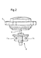
- FIG. 1 shows to illustrate an invention, a schematic representation of a preferred embodiment of a heating block 1 for water heaters, the one Turbine opening 6 has. This turbine opening 6 is closed by a screw cap 9 pressure and water resistant.
- a preferred means for flow measurement 8 On the top of this has a rotary closure 9 for closing the turbine port 6, by means of which the turbine port 6 can be closed pressure and water resistant.
- the rotary closure on an axis 10, wherein rotary closure 9 and axis 10 are integrally formed.
- a means for flow measurement 8 On the axis 10 is a means for flow measurement 8, which comprises a magnet 11 which is mounted freely rotatable.
- the flow rate measuring means 8 is an impeller. Characterized in that rotary closure 9 and axis 10 are integrally formed, the means for flow measurement 8 can be quickly and easily removed and cleaned or replaced without further assemblies such as pipes, etc. must be dismantled.
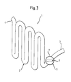
- FIG. 3 a preferred embodiment of a heating block 1 for water heaters, especially for water heater.
- This heating block 1 comprises a water inlet 3, a water outlet 4 and an inlet 3 and outlet 4 connecting tubing 5.
- a turbine port 6 in which a means for flow measurement 8, which includes a magnet 11a, 11b, can be used freely rotatable.
- the turbine opening 6 is closed pressure and water resistant.
- the invention can be aptly described as follows:
- the proposed construction is characterized in that the heating block 1 has an opening 6 which extends from the outside into the flow channel 7 of the heating block.
- This opening 6 is closed pressure-tight with a resealable rotary closure 9.
- an axis 10 is mounted on which a means for flow measurement 8 with magnets 11 a, 11 b is rotatably mounted.
- the means for flow measurement 8 extends into the flow channel 7 of the heating block 1 and is rotated by the water flow in rotation.
- a Hall sensor 12 is mounted externally, which detects the rotational movement of the magnet 11 a, 11 b by the wall thickness of the heating block 1.
- the device according to the invention advantageously offers the possibility of inexpensively integrating a measuring device for determining the flow into a heating block.
Landscapes
- Engineering & Computer Science (AREA)
- Physics & Mathematics (AREA)
- General Engineering & Computer Science (AREA)
- Thermal Sciences (AREA)
- Chemical & Material Sciences (AREA)
- Combustion & Propulsion (AREA)
- Mechanical Engineering (AREA)
- General Physics & Mathematics (AREA)
- Fluid Mechanics (AREA)
- Electromagnetism (AREA)
- Measuring Volume Flow (AREA)
- Instantaneous Water Boilers, Portable Hot-Water Supply Apparatuses, And Control Of Portable Hot-Water Supply Apparatuses (AREA)
- Heat-Pump Type And Storage Water Heaters (AREA)
Applications Claiming Priority (1)
| Application Number | Priority Date | Filing Date | Title |
|---|---|---|---|
| DE102007060190A DE102007060190A1 (de) | 2007-12-14 | 2007-12-14 | Heizblock für Warmwassergerät |
Publications (2)
| Publication Number | Publication Date |
|---|---|
| EP2071296A2 true EP2071296A2 (fr) | 2009-06-17 |
| EP2071296A3 EP2071296A3 (fr) | 2011-10-26 |
Family
ID=40635493
Family Applications (1)
| Application Number | Title | Priority Date | Filing Date |
|---|---|---|---|
| EP08105814A Withdrawn EP2071296A3 (fr) | 2007-12-14 | 2008-11-18 | Bloc de chauffage pour appareils d'eau chaude |
Country Status (2)
| Country | Link |
|---|---|
| EP (1) | EP2071296A3 (fr) |
| DE (1) | DE102007060190A1 (fr) |
Cited By (2)
| Publication number | Priority date | Publication date | Assignee | Title |
|---|---|---|---|---|
| EP3035005A1 (fr) * | 2014-12-18 | 2016-06-22 | BSH Hausgeräte GmbH | Ensemble rotorique, debitmetre, rotor et appareil transportant de l'eau |
| CN110220560A (zh) * | 2019-05-05 | 2019-09-10 | 广东万家乐燃气具有限公司 | 一种带温度探头的霍尔传感器及热水器 |
Families Citing this family (3)
| Publication number | Priority date | Publication date | Assignee | Title |
|---|---|---|---|---|
| EP2489951B1 (fr) | 2011-02-21 | 2017-04-05 | Gerdes OHG | Chauffe-eau instantané électrique |
| DE102012013344B4 (de) * | 2012-07-06 | 2023-06-07 | Stiebel Eltron Gmbh & Co. Kg | Heizblock |
| DE102016003763A1 (de) | 2016-04-01 | 2017-10-05 | Stiebel Eltron Gmbh & Co. Kg | Isolierkörper für einen Heizblock |
Citations (1)
| Publication number | Priority date | Publication date | Assignee | Title |
|---|---|---|---|---|
| EP1693651A2 (fr) | 2005-02-21 | 2006-08-23 | Gealan Formteile GmbH | Débitmètre à turbine |
Family Cites Families (5)
| Publication number | Priority date | Publication date | Assignee | Title |
|---|---|---|---|---|
| DE20221934U1 (de) * | 2001-08-04 | 2009-07-09 | Stiebel Eltron Gmbh & Co. Kg | Durchflussmesssensor |
| WO2004072562A2 (fr) * | 2003-02-12 | 2004-08-26 | Cem Cezayirli | Chauffe-eau instantane contigu de prechauffage |
| DE202004012263U1 (de) * | 2004-08-05 | 2004-10-07 | Stiebel Eltron Gmbh & Co. Kg | Durchlauferhitzer |
| PL1701111T3 (pl) * | 2005-03-11 | 2010-10-29 | Gerdes Ohg | Ogrzewacz przepływowy |
| EP2365294B1 (fr) * | 2007-07-19 | 2017-04-26 | Gealan Formteile GmbH | Appareil de détermination de l'écoulement |
-
2007
- 2007-12-14 DE DE102007060190A patent/DE102007060190A1/de not_active Ceased
-
2008
- 2008-11-18 EP EP08105814A patent/EP2071296A3/fr not_active Withdrawn
Patent Citations (1)
| Publication number | Priority date | Publication date | Assignee | Title |
|---|---|---|---|---|
| EP1693651A2 (fr) | 2005-02-21 | 2006-08-23 | Gealan Formteile GmbH | Débitmètre à turbine |
Cited By (2)
| Publication number | Priority date | Publication date | Assignee | Title |
|---|---|---|---|---|
| EP3035005A1 (fr) * | 2014-12-18 | 2016-06-22 | BSH Hausgeräte GmbH | Ensemble rotorique, debitmetre, rotor et appareil transportant de l'eau |
| CN110220560A (zh) * | 2019-05-05 | 2019-09-10 | 广东万家乐燃气具有限公司 | 一种带温度探头的霍尔传感器及热水器 |
Also Published As
| Publication number | Publication date |
|---|---|
| DE102007060190A1 (de) | 2009-06-18 |
| EP2071296A3 (fr) | 2011-10-26 |
Similar Documents
| Publication | Publication Date | Title |
|---|---|---|
| EP1693651B1 (fr) | Débitmètre à turbine | |
| EP2071296A2 (fr) | Bloc de chauffage pour appareils d'eau chaude | |
| EP1288494B1 (fr) | Dispositif pour déterminer la direction du vent | |
| DE102008055032B4 (de) | Anordnung und Verfahren zur Mehrphasendurchflussmessung | |
| EP2458225A1 (fr) | Plaque de recouvrement pour une pompe de roue centrifuge à vis et pompe de roue centrifuge à vis comprenant une telle plaque de recouvrement | |
| DE102009018056A1 (de) | Wasser-/Wärmezähler mit einem Gebergehäuse und Verfahren zur Herstellung eines Gebergehäuses | |
| DE102011013097A1 (de) | Kugelhahn | |
| EP3406806B1 (fr) | Dispositif d'armature pourvu d'armature combinée et unité de traitement de l'eau et procédé de préparation de l'eau potable | |
| EP2072970A1 (fr) | Procédé destiné à la détermination de la viscosité d'un liquide avec un débitmètre à tourbillons | |
| DE102005027888A1 (de) | Durchflussmessvorrichtung | |
| DE102005060887A1 (de) | Drehzahlregelgerät in fluidgekühlter Ausführung | |
| DE102019103272A1 (de) | Wasserarmatur zur Durchführung einer Hygienespülung | |
| DE102007061559A1 (de) | Kreiselpumpe mit Durchflusssensor | |
| EP1130341B1 (fr) | Dispositif de raccordement pour une pompe de chauffage | |
| DE102019104413A1 (de) | Druckmindereranordnung | |
| DE4039623C2 (de) | Vorrichtung mit Temperaturfühler zur Mischwasserbereitung | |
| DE10238416A1 (de) | Flüssigkeitszähler | |
| EP1413757A3 (fr) | Assemblage d'un moteur et d'une pompe | |
| DE202010013702U1 (de) | Wasserhahn-Temperaturanzeiger | |
| EP1033495B1 (fr) | Adapteur pour circuit de chauffage ou de refroidissement | |
| DE19909181B4 (de) | Serviceadapter für ein Heizungs- oder Kühlsystem | |
| DE4308782C2 (de) | Sanitärelement zum Einschrauben in eine Leitung | |
| DE202012101818U1 (de) | Vorrichtung zur Behandlung von Flüssigkeiten | |
| EP2075513A2 (fr) | Bloc de chauffage pour un appareil d'eau chaude | |
| EP3035005B1 (fr) | Ensemble rotorique, debitmetre, rotor et appareil transportant de l'eau |
Legal Events
| Date | Code | Title | Description |
|---|---|---|---|
| PUAI | Public reference made under article 153(3) epc to a published international application that has entered the european phase |
Free format text: ORIGINAL CODE: 0009012 |
|
| AK | Designated contracting states |
Kind code of ref document: A2 Designated state(s): AT BE BG CH CY CZ DE DK EE ES FI FR GB GR HR HU IE IS IT LI LT LU LV MC MT NL NO PL PT RO SE SI SK TR |
|
| AX | Request for extension of the european patent |
Extension state: AL BA MK RS |
|
| RIN1 | Information on inventor provided before grant (corrected) |
Inventor name: BAUER, FRANZ Inventor name: ENGLISCH, CHRISTIAN |
|
| PUAL | Search report despatched |
Free format text: ORIGINAL CODE: 0009013 |
|
| AK | Designated contracting states |
Kind code of ref document: A3 Designated state(s): AT BE BG CH CY CZ DE DK EE ES FI FR GB GR HR HU IE IS IT LI LT LU LV MC MT NL NO PL PT RO SE SI SK TR |
|
| AX | Request for extension of the european patent |
Extension state: AL BA MK RS |
|
| RIC1 | Information provided on ipc code assigned before grant |
Ipc: G01F 1/075 20060101AFI20110916BHEP Ipc: F24H 1/10 20060101ALI20110916BHEP Ipc: F24H 9/20 20060101ALI20110916BHEP |
|
| 17P | Request for examination filed |
Effective date: 20120426 |
|
| AKX | Designation fees paid |
Designated state(s): AT BE BG CH CY CZ DE DK EE ES FI FR GB GR HR HU IE IS IT LI LT LU LV MC MT NL NO PL PT RO SE SI SK TR |
|
| RAP1 | Party data changed (applicant data changed or rights of an application transferred) |
Owner name: BSH HAUSGERAETE GMBH |
|
| STAA | Information on the status of an ep patent application or granted ep patent |
Free format text: STATUS: THE APPLICATION IS DEEMED TO BE WITHDRAWN |
|
| 18D | Application deemed to be withdrawn |
Effective date: 20180602 |