EP2071211B1 - Schwingungsisolator zur Verwendung im Vakuum - Google Patents
Schwingungsisolator zur Verwendung im Vakuum Download PDFInfo
- Publication number
- EP2071211B1 EP2071211B1 EP08021035.4A EP08021035A EP2071211B1 EP 2071211 B1 EP2071211 B1 EP 2071211B1 EP 08021035 A EP08021035 A EP 08021035A EP 2071211 B1 EP2071211 B1 EP 2071211B1
- Authority
- EP
- European Patent Office
- Prior art keywords
- fluid
- vibration isolator
- arrangement
- vacuum
- tight chamber
- Prior art date
- Legal status (The legal status is an assumption and is not a legal conclusion. Google has not performed a legal analysis and makes no representation as to the accuracy of the status listed.)
- Active
Links
- 230000010355 oscillation Effects 0.000 title 1
- 239000012530 fluid Substances 0.000 claims description 20
- 239000000498 cooling water Substances 0.000 claims description 7
- 230000002093 peripheral effect Effects 0.000 description 6
- 239000012212 insulator Substances 0.000 description 4
- 238000002955 isolation Methods 0.000 description 4
- 238000004519 manufacturing process Methods 0.000 description 4
- 238000001816 cooling Methods 0.000 description 3
- 230000000694 effects Effects 0.000 description 2
- 238000005516 engineering process Methods 0.000 description 2
- 239000004065 semiconductor Substances 0.000 description 2
- 230000001133 acceleration Effects 0.000 description 1
- 239000002826 coolant Substances 0.000 description 1
- 239000012809 cooling fluid Substances 0.000 description 1
- 210000003746 feather Anatomy 0.000 description 1
- 238000009413 insulation Methods 0.000 description 1
- 230000010354 integration Effects 0.000 description 1
- 239000000463 material Substances 0.000 description 1
- 230000000750 progressive effect Effects 0.000 description 1
- 230000005855 radiation Effects 0.000 description 1
- 239000011347 resin Substances 0.000 description 1
- 229920005989 resin Polymers 0.000 description 1
- 238000007789 sealing Methods 0.000 description 1
Images


Classifications
-
- F—MECHANICAL ENGINEERING; LIGHTING; HEATING; WEAPONS; BLASTING
- F16—ENGINEERING ELEMENTS AND UNITS; GENERAL MEASURES FOR PRODUCING AND MAINTAINING EFFECTIVE FUNCTIONING OF MACHINES OR INSTALLATIONS; THERMAL INSULATION IN GENERAL
- F16F—SPRINGS; SHOCK-ABSORBERS; MEANS FOR DAMPING VIBRATION
- F16F9/00—Springs, vibration-dampers, shock-absorbers, or similarly-constructed movement-dampers using a fluid or the equivalent as damping medium
- F16F9/02—Springs, vibration-dampers, shock-absorbers, or similarly-constructed movement-dampers using a fluid or the equivalent as damping medium using gas only or vacuum
- F16F9/04—Springs, vibration-dampers, shock-absorbers, or similarly-constructed movement-dampers using a fluid or the equivalent as damping medium using gas only or vacuum in a chamber with a flexible wall
-
- F—MECHANICAL ENGINEERING; LIGHTING; HEATING; WEAPONS; BLASTING
- F16—ENGINEERING ELEMENTS AND UNITS; GENERAL MEASURES FOR PRODUCING AND MAINTAINING EFFECTIVE FUNCTIONING OF MACHINES OR INSTALLATIONS; THERMAL INSULATION IN GENERAL
- F16F—SPRINGS; SHOCK-ABSORBERS; MEANS FOR DAMPING VIBRATION
- F16F2230/00—Purpose; Design features
- F16F2230/30—Sealing arrangements
Definitions
- the invention relates to a vibration isolator and an arrangement with a vibration isolator.
- Vibration isolators are known.
- Such insulators as used, for example, for lithographic devices, usually comprise an open or closed air spring, which preferably has a low natural frequency both vertically and horizontally.
- vibration isolators In addition to an air spring, other components such as motors for horizontal and / or vertical adjustment, sensors or actuators, in order to actively influence the system, are usually integrated in such vibration isolators.
- a vibration isolation system is for example in the European patent specification EP 0 927 380 B1 described.
- the European Patent Application EP 1 803 963 describes a horizontally and vertically effective air bearing.
- Another vibration isolator is from the US 2002/0140916 known. Full reference is made to the generic devices described in the above documents.
- the devices used are extremely sensitive to vibrations, which can also continue over the ground to the respective devices. Therefore, such machines, such as wafer exposure machines, stored vibration isolated.
- vibration isolators in particular of encapsulated air bearings, has the disadvantage that now peripheral components such as electrical leads, electronic control modules, sensors or supply lines for coolant supply are exposed to vacuum conditions.
- the invention is based on the object to provide a vibration isolator or an arrangement or a system with a vibration isolator, in which the said disadvantages of the prior art are at least reduced.
- Another object of the invention is to improve the cooling of active components such as motors, actuators and electrical controls.
- Another object of the invention is to reduce the leakage caused by a vibration isolator in a vacuum system.
- the object of the invention is already achieved by a vibration isolator according to one of the independent claims and by an arrangement with a vibration isolator.
- a vibration isolator for use in vacuum is provided.
- any negative pressure below ambient pressure is understood, ie a range from rough vacuum to ultrahigh vacuum.
- the vibration isolator comprises a spring, which is preferably designed as an air spring.
- the spring comprises a substantially fluid-tight space, which in particular forms the working space of an air spring. If the spring is designed as an air spring, it is preferably a particular encapsulated with a bellows air spring. In an alternative embodiment of the invention, however, an open air bearing with a low leakage rate can also be used.
- At least one electrical module, an electronic module, a mechanical or magnetic spring and / or at least one fluid supply is arranged in the fluid-tight space.
- peripheral modules which are functional components of the vibration isolator, are arranged in the fluid-tight space.
- the fluid-tight space preferably forms a working space of the vibration isolator.
- the electronic modules may be, for example, sensors such as position sensors, acceleration sensors or geophones.
- actuators such as electromagnets, motors, in particular linear motors act.
- a preferred embodiment of the invention prevails in the fluid-tight space relative to the environment, in particular with respect to the vacuum, an overpressure of more than 0.3 bar, preferably more than 0.8 bar and more preferably more than 1 bar.
- An overpressure of up to 8 bar usually makes no special demands on the materials of the components.
- the air acts as an insulator
- good convection of the respective components can be achieved by convection of the air.
- the vibration isolator has at least one fluid supply, in particular it has a fluid supply for cooling water or air, wherein the electrical or electronic modules arranged in the fluid-tight space can be cooled at least partially via the fluid.
- the invention further relates to a vibration isolator for use in vacuum, comprising a spring having a substantially fluid-tight space.
- the substantially fluid-tight space is sealed against the surrounding vacuum via at least two successively arranged seals, wherein in the region which lies between the seals, at least one fluid line leads, by means of which via a vacuum pump, a negative pressure relative to the fluid-tight space can be generated.
- a negative pressure is already generated after the first seal.
- the first seal so the seal which faces the fluid-tight space, however, is designed for higher pressure differences, but on the other hand has a higher leakage rate compared to the second vacuum-side seal.
- the pressure difference behind the second vacuum-side seal against the vacuum is at most 0.6, preferably 0.4 and more preferably at a maximum of 0.1 bar.
- the pressure difference with respect to the fluid-tight space under overpressure is at least 1, preferably at least 3 and particularly preferably at least 5 bar.
- the invention further relates to an arrangement with a vibration isolator, wherein the vibration isolator is arranged in a vacuum chamber.
- Vacuum chamber and / or vibration isolator are provided with fluid passages or electrical feedthroughs, which lead to the fluid-tight space.
- sensors via electrical feedthroughs, sensors, actuators and other electrical components can be controlled.
- air for operating an air spring or a cooling fluid can be carried out via fluid passages.
- the fluid passages and electrical feedthroughs end in the fluid-tight space, so do not need to be continued in the vacuum area.
- the leakage rate caused by the vibration isolator can be significantly reduced in a vacuum system.
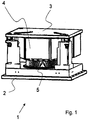
- Fig. 1 should the essential components of a vibration isolator 1 are explained in more detail with reference to a schematic representation.
- the vibration isolator 1 comprises a base 2 and a plate 3 on which a load (not shown) can be mounted vibration-isolated.
- a spring is arranged, which is formed in this embodiment as an air spring.
- the spring 4 comprises a working space with a bellows 5 and thus forms a substantially fluid-tight space. It is in the form of an air spring spring 4 so a closed air spring.
- Such air springs have the advantage of a low natural frequency and can be simultaneously formed vertically and horizontally effective.
- Fig. 2 shows a schematic rear view of the in Fig. 1 illustrated vibration isolator.
- an air supply 8 is provided, via which the air spring formed as a spring 4 can be supplied with working pressure.
- the electrical lines and fluid lines thus present lead in the vibration isolator 1, which can be installed in a vacuum chamber, directly into the fluid-tight space.
- the vibration isolator 1 When the vibration isolator 1 is mounted with its base 2 in a vacuum chamber, only the base 2 needs to be sealed against the vacuum chamber (not shown).
- the leak rate of the vacuum system caused by the vibration isolation bearing 1 can be reduced.
- the electrical and mechanical modules such as actuators, sensors, motors, etc. arranged in the fluid-tight space defined by the air spring need not be dimensioned for use in vacuum and can be much simpler via the supply of cooling water or cooling air be cooled.
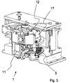
- Fig. 3 shows an isometric view of a vibration isolator, which is shown in the partially broken state.
- the bellows 5 can be seen only in the rear area and hidden in the front area, so that the arranged in the fluid-tight space modules can be seen.
- a motor 11 is arranged in the fluid-tight space, through which the vibration isolation bearing 1 can be calibrated in terms of height.
- a sensor module 12 with at least two position sensors (not shown) for each one spatial direction is located in the fluid-tight space.
- a geophone 15 is provided in particular for detecting vibrations caused by earth vibrations.
- Fig. 4 shows one of the Fig. 3 taken detail view, based on which the sealing of the fluid-tight space to be explained against the vacuum.
- the seals 13 and 14 provided.
- the pressure-side seal 13 is preferably formed in this embodiment as an O-ring.
- the vacuum-side seal 14 is a low-leakage seal which effects it However, unfolded only at relatively low pressure differences.
- a fluid line which may be of any design (not shown), pumped between the vacuum-side seal 14 and the pressure-side seal 13, so that already applied between the seal 13 and 14, a vacuum.
Description
- Die Erfindung betrifft einen Schwingungsisolator sowie eine Anordnung mit einem Schwingungsisolator.
- Schwingungsisolatoren sind bekannt. Derartige Isolatoren, wie sie beispielsweise für Lithographiegeräte eingesetzt werden, umfassen üblicherweise eine offene oder geschlossene Luftfeder, welche vorzugsweise sowohl vertikal als auch horizontal eine niedrige Eigenfrequenz aufweist.
- Mit derartigen Isolatoren lassen sich hohe Isolationswirkungen erzielen.
- Neben einer Luftfeder sind in derartigen Schwingungsisolatoren zumeist noch andere Komponenten, wie Motoren zur horizontalen und/oder vertikalen Einstellung, Sensoren oder Aktoren, um das System aktiv zu beeinflussen, integriert.
- Ein Schwingungsisolationssystem ist beispielsweise in der Europäischen Patentschrift
EP 0 927 380 B1 beschrieben. Die Europäische PatentanmeldungEP 1 803 963 beschreibt ein horizontal und vertikal wirksames Luftlager. Ein weiterer Schwingungsisolator ist aus derUS 2002/0140916 bekannt. Auf die in vorstehenden Dokumenten beschriebenen gattungsbildenden Vorrichtungen wird vollumfänglich Bezug genommen. - Im Zuge fortschreitender Miniaturisierung in der Halbleitertechnologie ist es zunehmend nötig, die Produktion von Halbleiterbauteilen zumindest teilweise in einem Vakuum durchzuführen. Nur so können beispielsweise kleinste Chipstrukturen in der nötigen Genauigkeit abgebildet werden. Auch bei der Produktion von Displays wird teilweise auf Vakuumtechnologien zurückgegriffen, insbesondere kann eine Produktion nicht nur in geschlossenen Vakuumkammern, sondern auch in einem sogenannten offenen Vakuum stattfinden.
- Trotz des Vakuums sind die verwendeten Geräte äußerst empfindlich gegen Schwingungen, welche sich auch über den Boden zu den jeweiligen Geräten fortsetzen können. Daher werden derartige Maschinen, wie Waferbelichtungsmaschinen, schwingungsisoliert gelagert.
- Der Einsatz von bekannten Schwingungsisolatoren, insbesondere von gekapselten Luftlagern, hat den Nachteil, daß nunmehr Peripheriekomponenten wie elektrische Zuleitungen, elektronische Steuerungsmodule, Sensoren oder Zuleitungen für Kühlmittelzufuhr Vakuumbedingungen ausgesetzt sind.
- Daher ist zum einen eine besondere Dimensionierung der Peripheriekomponenten auf Vakuumbedingungen nötig, damit es nicht zu Beschädigungen, beispielsweise von elektrischen Komponenten aufgrund der bei bestimmten Drücken stark reduzierten Überschlagspannungen kommt. Auch fertigungsbedingte Einschlüsse von Luftblasen, wie zum Beispiel von Bauteilen, welche in Harz vergossen sind, vorkommen, können zu Beschädigungen führen.
- Des weiteren erfolgt im Vakuum die Wärmeabgabe von Komponenten fast ausschließlich über Wärmestrahlung und Wärmeleitung. So können benachbarte Geräte gestört werden oder das jeweilige Bauteil überhitzen.
- Auch bewirken die notwendigen Kabel und Fluiddurchführungen Leckagen, welche das Vakuum verunreinigen.
- Der Erfindung liegt demgegenüber die Aufgabe zugrunde, einen Schwingungsisolator beziehungsweise eine Anordnung oder ein System mit einem Schwingungsisolator bereit zu stellen, bei welchen die genannten Nachteile des Stands der Technik zumindest reduziert sind.
- Es ist insbesondere eine Aufgabe der Erfindung auf eine Auslegung von elektrischen und/oder mechanischen Peripheriekomponenten, wie Sensoren, Aktoren etc., für Vakuumbedingungen verzichten zu können.
- Eine weitere Aufgabe der Erfindung ist es, die Kühlung aktiver Bauelemente wie Motoren, Aktoren und elektrischen Steuerungen zu verbessern.
- Eine weitere Aufgabe der Erfindung ist es, die durch einen Schwingungsisolator in einem Vakuumsystem verursachte Leckage zu verringern.
- Insbesondere soll die Leckage zwischen einem Isolatorgehäuse und einer Vakuumkammer reduziert werden.
- Die Aufgabe der Erfindung wird bereits durch einen Schwingungsisolator nach einem der unabhängigen Ansprüche sowie durch eine Anordnung mit einem Schwingungsisolator gelöst.
- Bevorzugte Ausführungsform und Weiterbildung der Erfindung sind den jeweiligen Unteransprüchen zu entnehmen.
- Danach ist ein Schwingungsisolator zur Verwendung im Vakuum vorgesehen. Unter einem Vakuum im Sinne der Erfindung wird jeder Unterdruck unterhalb Umgebungsdruck verstanden, also ein Bereich vom Grobvakuum bis zum Ultrahochvakuum.
- Der Schwingungsisolator umfaßt eine Feder, welche vorzugsweise als Luftfeder ausgestaltet ist. Die Feder umfaßt einen im wesentlichen fluiddichten Raum, welcher insbesondere den Arbeitsraum einer Luftfeder bildet. Sofern die Feder als Luftfeder ausgestaltet ist, handelt es sich vorzugsweise um eine insbesondere mit einem Faltenbalg eingekapselte Luftfeder. Bei einer alternativen Ausführungsform der Erfindung kann aber auch ein offenes Luftlager mit geringer Leckrate verwendet werden.
- Gemäß der Erfindung ist zumindest ein elektrisches Modul, ein Elektronikmodul, eine mechanische oder magnetische Feder und/oder zumindest eine Fluidzuführung in dem fluiddichten Raum angeordnet.
- Vorzugsweise werden also Peripheriemodule, welche Funktionskomponenten des Schwingungsisolators sind, in dem fluiddichten Raum angeordnet.
- Es ist aber auch denkbar, Bauteile, welche nicht in unmittelbaren Zusammenhang mit dem Schwingungsisolator stehen, in dem fluiddichten Raum anzuordnen.
- In dem fluiddichten Raum herrscht gegenüber dem Vakuum ein Überdruck, so daß die jeweiligen Module beziehungsweise Komponenten nicht für den Einsatz im Vakuum konzipiert werden müssen.
- Gleichzeitig bildet der fluiddichte Raum vorzugsweise einen Arbeitsraum des Schwingungsisolators.
- Bei den Elektronikmodulen kann es sich beispielsweise um Sensoren wie Positionssensoren, Beschleunigungssensoren oder Geophone handeln.
- Weiter kann es sich um Aktoren, wie Elektromagnete, Motoren, insbesondere Linearmotoren, handeln.
- Aber auch die Integration von weiteren mechanischen Bauteilen ist denkbar, insbesondere von Federn, Knickpendeln, etc., welche ebenfalls Funktionselemente des Schwingungsisolators sind.
- Bei einer bevorzugten Ausführungsform der Erfindung herrscht in dem fluiddichten Raum gegenüber der Umgebung, insbesondere gegenüber dem Vakuum ein Überdruck von mehr als 0,3 Bar, vorzugsweise von mehr als 0,8 Bar und besonders bevorzugt von mehr als 1 Bar.
- Es hat sich gezeigt, daß für Normaldruck konzipierte Komponenten ohne weitere konstruktive Eingriffe häufig bei Überdrücken von bis zu 8 Bar verwendbar sind, beziehungsweise mit relativ geringem Aufwand gegenüber Druck geschützt werden können.
- Ein Überdruck von bis zu 8 Bar stellt in der Regel keine besonderen Anforderungen an die Materialien der Komponenten.
- So wirkt die Luft zum einen als Isolator, zum anderen kann durch Konvektion der Luft eine gute Kühlung der jeweiligen Bauteile erreicht werden.
- Der Schwingungsisolator weist bei einer bevorzugten Ausführungsform der Erfindung zumindest eine Fluidzuführung auf, insbesondere weist er eine Fluidzuführung für Kühlwasser oder Luft auf, wobei die in dem fluiddichten Raum angeordneten elektrischen oder elektronischen Module zumindest teilweise über das Fluid kühlbar sind.
- Gleichzeitig kann über das Fluid, welches zur Kühlung vorgesehen ist, der vorzugsweise als Luftfeder ausgebildete Schwingungsisolator betrieben werden.
- Die Erfindung betrifft des weiteren einen Schwingungsisolator zur Verwendung im Vakuum, welcher eine Feder, die einen im wesentlichen fluiddichten Raum aufweist, umfaßt.
- Gemäß der Erfindung ist der im wesentlichen fluiddichte Raum über zumindest zwei nacheinander angeordneten Dichtungen gegenüber den umgebenden Vakuum abgedichtet, wobei in den Bereich, welcher zwischen den Dichtungen liegt, zumindest eine Fluidleitung führt, mittels der über eine Vakuumpumpe ein Unterdruck gegenüber dem fluiddichten Raum erzeugbar ist.
- Es wird also aus Sicht der Vakuumkammer bereits nach der ersten Dichtung ein Unterdruck erzeugt. Vorzugsweise besteht so zwischen zweiter Dichtung und dem Vakuum nur eine relativ geringere Druckdifferenz.
- Es hat sich gezeigt, daß so als zweite vakuumseitige Dichtung eine Dichtung verwendet werden kann, welche zwar nur zum Einsatz bei geringen Druckdifferenzen ausgebildet ist, aber eine äußerst geringe Leckrate aufweist.
- Die erste Dichtung, also die Dichtung welche dem fluiddichten Raum zugewandt ist, ist dagegen für höhere Druckdifferenzen ausgebildet, hat dagegen aber eine höhere Leckrate gegenüber der zweiten vakuumseitigen Dichtung.
- Vorzugsweise liegt die Druckdifferenz hinter der zweiten vakuumseitigen Dichtung gegenüber dem Vakuum bei maximal 0,6, vorzugsweise 0,4 und besonders bevorzugt bei maximal 0,1 Bar.
- Dagegen beträgt die Druckdifferenz gegenüber dem fluiddichten unter Überdruck stehenden Raum mindestens 1, vorzugsweise mindestens 3 und besonders bevorzugt mindestens 5 Bar.
- Die Erfindung betrifft des weiteren eine Anordnung mit einem Schwingungsisolator, wobei der Schwingungsisolator in einer Vakuumkammer angeordnet ist.
- Vakuumkammer und/oder Schwingungsisolator sind dabei mit Fluiddurchführungen oder elektrischen Durchführungen versehen, welche zum fluiddichten Raum führen.
- So können, beispielsweise über elektrische Durchführungen, Sensoren, Aktoren und andere elektrische Bauteile angesteuert werden.
- Über Fluiddurchführungen kann beispielsweise Luft zum Betrieb einer Luftfeder oder ein Kühlfluid durchgeführt werden.
- Vorteilhaft ist dabei insbesondere, daß die Fluiddurchführungen und elektrischen Durchführungen in dem fluiddichten Raum enden, also nicht in den Vakuumbereich weiter geführt sein müssen. So kann die durch den Schwingungsisolator bedingte Leckrate in einer Vakuumanlage erheblich reduziert werden.
- Die Erfindung soll im Folgenden anhand der Zeichnungen
Fig. 1 bis Fig. 4 näher erläutert werden. -
Fig. 1 zeigt eine schematische Seitenansicht eines Ausführungsbeispiels eines Schwingungsisolators. -
Fig. 2 zeigt schematisch einen Schwingungsisolator von unten. -
Fig. 3 zeigt eine schematische teilweise aufgebrochene isometrische Ansicht eines Schwingungsisolators. -
Fig. 4 zeigt eine Detailansicht. - Bezugnehmend auf
Fig. 1 sollen die wesentlichen Bestandteile eines Schwingungsisolators 1 anhand einer schematischen Darstellung näher erläutert werden. - Der Schwingungsisolator 1 umfaßt eine Basis 2 sowie eine Platte 3 auf welcher eine Last (nicht dargestellt) schwingungsisoliert gelagert werden kann.
- Zwischen der Basis 2 und der Platte 3, ist einen Feder angeordnet, welche in diesem Ausführungsbeispiel als Luftfeder ausgebildet ist. Die Feder 4 umfaßt einen Arbeitsraum mit einem Faltenbalg 5 und bildet so einen im wesentlichen fluiddichten Raum. Es handelt sich bei der als Luftfeder ausgebildeten Feder 4 also um eine geschlossene Luftfeder.
- Derartige Luftfedern haben den Vorteil einer niedrigen Eigenfrequenz und können gleichzeitig vertikal und horizontal wirksam ausgebildet sein.
-
Fig. 2 zeigt eine schematische Rückansicht des inFig. 1 dargestellten Schwingungsisolators. - Zu erkennen ist die Basis 2, an welcher die verschiedenen Zuführungen für Peripheriekomponenten zum Betrieb des Schwingungsisolators angebracht sind.
- So befinden sich an der Basis eine Kühlwasserzuführung 6 sowie ein Kühlwasserablauf 7, über welche in dem fluiddichten Raum angeordnete elektrische und elektronische Bauelemente gekühlt werden können.
- Weiter ist eine Luftzuführung 8 vorgesehen, über welche die als Luftfeder ausgebildete Feder 4 mit Arbeitsdruck versorgt werden kann.
- Darüber hinaus gibt es noch Anschlüsse für Sensoren 9, sowie einen Anschluß für einen Aktor 10.
- Die so vorhandenen elektrischen Leitungen und Fluidleitungen führen bei dem Schwingungsisolator 1, welcher in eine Vakuumkammer eingebaut werden kann, direkt in den fluiddichten Raum. Wenn der Schwingungsisolator 1 mit seiner Basis 2 in einer Vakuumkammer montiert wird, braucht nur die Basis 2 gegen die Vakuumkammer (nicht dargestellt) abgedichtet zu werden.
- Weitere Durchführungen für Peripherimodule des Schwingungsisolationslagers 1 sind in der Vakuumkammer nicht erforderlich.
- Dadurch kann die durch das Schwingungsisolationslager 1 verursachte Leckrate des Vakuumsystems herabgesetzt werden. Des weiteren brauchen in diesem Ausführungsbeispiel die in dem durch die Luftfeder definierten fluiddichten Raum angeordneten elektrischen und mechanischen Module wie Aktoren, Sensoren, Motoren, etc., nicht für die Verwendung im Vakuum dimensioniert zu sein und können wesentlich einfacher über die Zuführung von Kühlwasser oder Kühlluft gekühlt werden.
-
Fig. 3 zeigt eine isometrische Ansicht eines Schwingungsisolators, welcher im teilweise aufgebrochenen Zustand dargestellt ist. - In dieser Darstellung ist insbesondere der fluiddichte Raum aufgebrochen. So ist der Faltenbalg 5 nur im hinteren Bereich zu erkennen und im vorderen Bereich ausgeblendet, so daß die in dem fluiddichten Raum angeordneten Module zu erkennen sind.
- In diesem Ausführungsbeispiel ist in dem fluiddichten Raum ein Motor 11 angeordnet, über welchen das Schwingungsisolationslager 1 hinsichtlich der Höhe kalibriert werden kann.
- Des weiteren befindet sich in dem fluiddichten Raum ein Sensormodul 12 mit zumindest zwei Positionssensoren (nicht dargestellt) für jeweils eine Raumrichtung. Insbesondere zur Erfassung von durch Erderschütterungen hervorgerufenen Schwingungen ist des weiteren ein Geophon 15 vorgesehen.
-
Fig. 4 zeigt eine derFig. 3 entnommene Detailansicht, anhand welcher die Abdichtung des fluiddichten Raums gegen das Vakuum näher erläutert werden soll. - Zur Abdichtung sind zwei Dichtungen, die Dichtungen 13 und 14, vorgesehen.
- Dabei ist die druckseitige Dichtung 13 in diesem Ausführungsbeispiel vorzugsweise als O-Ring ausgebildet.
- Bei der vakuumseitigen Dichtung 14 handelt es sich um eine Dichtung mit geringer Leckrate, welche ihre Wirkung allerdings nur bei relativ geringen Druckdifferenzen entfaltet.
- Daher wird über eine Fluidleitung, welche beliebig ausgebildet sein kann (nicht dargestellt), zwischen der vakuumseitigen Dichtung 14 und der druckseitigen Dichtung 13 abgepumpt, so daß bereits zwischen den Dichtung 13 und 14 ein Vakuum anliegt.
- Durch diese Anordnung konnte die durch den Schwingungsisolator bedingte Leckrate weiter reduziert werden.
- Es versteht sich, daß die Erfindung nicht auf eine Kombination vorbeschriebener Merkmale beschränkt ist, sondern daß der Fachmann sämtliche beschriebenen Merkmale soweit dies technisch sinnvoll ist, kombinieren wird.
-
- 1
- - Schwingungsisolator
- 2
- - Basis
- 3
- - Platte
- 4
- - Feder
- 5
- - Faltenbalg
- 6
- - Kühlwasserzufuhr
- 7
- - Kühlwasserablauf
- 8
- - Luftzuführung
- 9
- - Anschlüsse Sensoren
- 10
- - Anschluß Aktor
- 11
- - Motor
- 12
- - Sensormodul
- 13
- - Dichtung
- 14
- - Dichtung
- 15
- - Geophon
Claims (14)
- Anordnung mit zumindest einem Schwingungsisolator (1), welcher in einer Vakuumkammer angeordnet ist, wobei der Schwingungsisolator eine Feder (4) umfasst, die einen im Wesentlichen fluiddichten Raum aufweist, wobei der im Wesentlichen fluiddichte Raum über zumindest zwei nacheinander angeordnete Dichtungen (13,14) gegenüber dem umgebenden Vakuum abgedichtet ist, dadurch kennzeichnet, dass in einen Raum zwischen den Dichtungen (13,14) zumindest eine Fluidleitung führt, mittels der ein Unterdruck gegenüber dem fluiddichten Raum erzeugbar ist.
- Anordnung mit zumindest einem Schwingungsisolator (1) nach dem vorstehenden Anspruch, dadurch gekennzeichnet, daß über die zumindest eine Fluidleitung ein Unterdruck erzeugbar ist, der maximal 0,6, vorzugsweise 0,4 und besonders bevorzugt maximal 0,1 bar höher ist, als der Druck eines umgebenden Volumens, insbesondere eines umgebenden Vakuums.
- Anordnung mit zumindest einem Schwingungsisolator (1) nach einem der vorstehenden beiden Ansprüche, dadurch gekennzeichnet, daß über die zumindest eine Fluidleitung ein Unterdruck erzeugbar ist, der mindestens 1, vorzugsweise mindestens 3 und besonders bevorzugt mindestens 5 bar niedriger ist, als der Druck in dem fluiddichten Raum.
- Anordnung mit zumindest einem Schwingungsisolator (1) zur Verwendung im Vakuum, umfassend zumindest eine Feder, die einen im Wesentlichen fluiddichten Raum aufweist, wobei zumindest ein elektrisches Modul, ein Elektronikmodul, eine mechanische oder magnetische Feder (4) und/oder zumindest eine Fluidzuführung in dem fluiddichten Raum angeordnet ist.
- Anordnung mit zumindest einem Schwingungsisolator (1) nach Anspruch 1, dadurch gekennzeichnet, daß es sich bei dem Elektronikmodul um einen Sensor handelt.
- Anordnung mit zumindest einem Schwingungsisolator (1) nach Anspruch 1, dadurch gekennzeichnet, daß es sich bei dem Elektronikmodul um einen Aktor handelt.
- Anordnung mit zumindest einem Schwingungsisolator (1) nach einem der vorstehenden Ansprüche, dadurch gekennzeichnet, daß es sich bei dem elektrischen Modul um einen Motor (11) oder einen Elektromagneten handelt.
- Anordnung mit zumindest einem Schwingungsisolator (1) nach einem der vorstehenden Ansprüche, dadurch gekennzeichnet, daß es sich bei der mechanischen Feder (4) um eine Blattfeder handelt.
- Anordnung mit zumindest einem Schwingungsisolator nach einem der vorstehenden Ansprüche, dadurch gekennzeichnet, daß in dem fluiddichten Raum gegenüber der Umgebung ein Überdruck von mehr als 0,3 bar, vorzugsweise von mehr als 0,8 bar und besonders bevorzugt von mehr als 1 bar herrscht.
- Anordnung mit zumindest einem Schwingungsisolator (1) nach einem der vorstehenden Ansprüche, dadurch gekennzeichnet, daß in dem fluiddichten Raum gegenüber dem Atmosphärendruck ein Überdruck 0,5 bis 15 bar, bevorzugt von 1 bis 10 bar und besonders bevorzugt von 5 bis 8 bar herrscht.
- Anordnung mit zumindest einem Schwingungsisolator (1) nach einem der vorstehenden Ansprüche, dadurch gekennzeichnet, daß der Schwingungsisolator eine Fluidzuführung, insbesondere für Kühlwasser oder Luft aufweist, wobei in dem fluiddichten Raum angeordnete elektrische oder elektronische Module zumindest teilweise über das Fluid kühlbar sind.
- Anordnung mit zumindest einem Schwingungsisolator (1) nach einem der vorstehenden Ansprüche, dadurch gekennzeichnet, daß der Schwingungsisolator als Luftlager, insbesondere als vertikal und horizontal wirksames Luftlager ausgebildet ist.
- Anordnung mit zumindest einem Schwingungsisolator (1) nach einem der vorstehenden Ansprüche, dadurch gekennzeichnet, daß die Vakuumkammer und/oder der Schwingungsisolator (1) Fluiddurchführungen zum fluiddichten Raum aufweist.
- Anordnung mit zumindest einem Schwingungsisolator (1) nach dem vorstehenden Anspruch, dadurch gekennzeichnet, daß die Vakuumkammer und/oder der Schwingungsisolator (1) elektrische Durchführungen zum fluiddichten Raum aufweist.
Applications Claiming Priority (1)
| Application Number | Priority Date | Filing Date | Title |
|---|---|---|---|
| DE102007059631A DE102007059631B4 (de) | 2007-12-10 | 2007-12-10 | Schwingungsisolator zur Verwendung im Vakuum |
Publications (3)
| Publication Number | Publication Date |
|---|---|
| EP2071211A2 EP2071211A2 (de) | 2009-06-17 |
| EP2071211A3 EP2071211A3 (de) | 2013-06-12 |
| EP2071211B1 true EP2071211B1 (de) | 2018-01-24 |
Family
ID=40380051
Family Applications (1)
| Application Number | Title | Priority Date | Filing Date |
|---|---|---|---|
| EP08021035.4A Active EP2071211B1 (de) | 2007-12-10 | 2008-12-04 | Schwingungsisolator zur Verwendung im Vakuum |
Country Status (4)
| Country | Link |
|---|---|
| US (1) | US8387958B2 (de) |
| EP (1) | EP2071211B1 (de) |
| JP (1) | JP5094692B2 (de) |
| DE (1) | DE102007059631B4 (de) |
Families Citing this family (6)
| Publication number | Priority date | Publication date | Assignee | Title |
|---|---|---|---|---|
| EP2730801A1 (de) | 2012-11-07 | 2014-05-14 | Integrated Dynamics Engineering GmbH | Als pneumatische Feder ausgebildeter Schwingungsisolator sowie Verfahren zur Abstimmung eines Schwingungsisolators |
| EP2772661B1 (de) | 2013-02-28 | 2020-04-01 | Integrated Dynamics Engineering GmbH | Verfahren zur dimensionierung eines schwingungsisolators |
| EP3181944B1 (de) | 2015-12-16 | 2023-04-26 | Integrated Dynamics Engineering GmbH | Schwingungsisolator mit einer vertikal wirksamen pneumatischen feder |
| DE102016110667A1 (de) * | 2016-06-09 | 2017-12-14 | Eto Magnetic Gmbh | Dämpfungsvorrichtung und Verfahren mit einer Dämpfungsvorrichtung |
| EP3260732B1 (de) * | 2016-06-23 | 2019-03-27 | Integrated Dynamics Engineering GmbH | Pneumatischer aktor sowie verfahren zum betrieb eines aktiven schwingungsisolationssystem |
| EP3260733B1 (de) | 2016-06-23 | 2019-08-07 | Integrated Dynamics Engineering GmbH | Aktives stationäres schwingungsisolationssystem |
Family Cites Families (17)
| Publication number | Priority date | Publication date | Assignee | Title |
|---|---|---|---|---|
| US5060959A (en) * | 1988-10-05 | 1991-10-29 | Ford Motor Company | Electrically powered active suspension for a vehicle |
| US5285699A (en) * | 1988-12-07 | 1994-02-15 | Board Of Regents, University Of Texas System | Reinforced composite flywheels and shafts |
| JP3042763B2 (ja) * | 1995-10-04 | 2000-05-22 | 株式会社荏原製作所 | 除振装置 |
| KR100522886B1 (ko) | 1997-07-22 | 2005-10-19 | 에이에스엠엘 네델란즈 비.브이. | 가스베어링을 구비한 지지장치 |
| US7095482B2 (en) * | 2001-03-27 | 2006-08-22 | Nikon Corporation | Multiple system vibration isolator |
| US6731372B2 (en) * | 2001-03-27 | 2004-05-04 | Nikon Corporation | Multiple chamber fluid mount |
| TWI230844B (en) | 2002-06-07 | 2005-04-11 | Asml Netherlands Bv | Lithographic apparatus and device manufacturing method |
| JP2004071818A (ja) | 2002-08-06 | 2004-03-04 | Nikon Corp | 支持装置およびステージ装置並びに露光装置 |
| US20040032064A1 (en) * | 2002-08-13 | 2004-02-19 | Jackson James Joshua | Tunable pneumatic mount |
| JP2004124745A (ja) | 2002-09-30 | 2004-04-22 | Mazda Motor Corp | ターボ過給機付エンジン |
| JP2005106166A (ja) * | 2003-09-30 | 2005-04-21 | Nikon Corp | アクティブ除振装置及び露光装置 |
| JP2005282696A (ja) | 2004-03-29 | 2005-10-13 | Canon Inc | 除振マウント装置、露光装置及びデバイス製造方法 |
| IL161900A (en) * | 2004-05-09 | 2011-01-31 | Rami Ben Maimon | Vibration reliever for vacuum pump |
| EP1751621A2 (de) * | 2004-05-14 | 2007-02-14 | Koninklijke Philips Electronics N.V. | Vibrationsdämpfer oder isolator |
| JP2006283966A (ja) | 2005-03-10 | 2006-10-19 | Kurashiki Kako Co Ltd | アクティブ除振装置 |
| EP1744215B1 (de) | 2005-07-16 | 2012-09-12 | Integrated Dynamics Engineering GmbH | Tragevorrichtung für vibrationsempfindliche Komponente |
| EP1803963B1 (de) | 2005-12-30 | 2009-08-26 | Integrated Dynamics Engineering GmbH | Hybrides Steifigkeitsmodul zur Schwingungsisolation |
-
2007
- 2007-12-10 DE DE102007059631A patent/DE102007059631B4/de active Active
-
2008
- 2008-12-04 EP EP08021035.4A patent/EP2071211B1/de active Active
- 2008-12-08 US US12/330,192 patent/US8387958B2/en active Active
- 2008-12-10 JP JP2008314116A patent/JP5094692B2/ja active Active
Non-Patent Citations (1)
| Title |
|---|
| None * |
Also Published As
| Publication number | Publication date |
|---|---|
| JP5094692B2 (ja) | 2012-12-12 |
| DE102007059631A1 (de) | 2009-06-25 |
| US8387958B2 (en) | 2013-03-05 |
| DE102007059631B4 (de) | 2009-09-17 |
| JP2009197998A (ja) | 2009-09-03 |
| US20090146352A1 (en) | 2009-06-11 |
| EP2071211A2 (de) | 2009-06-17 |
| EP2071211A3 (de) | 2013-06-12 |
Similar Documents
| Publication | Publication Date | Title |
|---|---|---|
| EP2071211B1 (de) | Schwingungsisolator zur Verwendung im Vakuum | |
| DE102010060886B4 (de) | Motorlager für ein Kraftfahrzeug | |
| EP1852613B1 (de) | Vakuumpumpe mit Gehäuse | |
| EP1803964B1 (de) | Lager zur Schwingungsisolation mit verringerter horizontaler Steifigkeit | |
| DE102010060885A1 (de) | Motorlager für ein Kraftfahrzeug | |
| EP3260732B1 (de) | Pneumatischer aktor sowie verfahren zum betrieb eines aktiven schwingungsisolationssystem | |
| EP1520994A2 (de) | Hydraulische Anordnung und Verfahren für eine solche | |
| EP2128700B1 (de) | Lithographiesystem und Verfahren zur Regelung eines Lithographiesystems | |
| EP2100023A1 (de) | Ventil-steuervorrichtung | |
| DE3921824A1 (de) | Daempfungssockel | |
| EP2359098A1 (de) | Differenzdruckmessumformer | |
| DE102006046488A1 (de) | Dichtung einer elektrischen Steuereinheit einer Hydraulikmaschine | |
| EP1870614B1 (de) | Aktives Schwingungsisolationssystem mit verbesserter Sensoren-/Aktorenabstimmung | |
| EP3050745B1 (de) | Pneumatische steuer- und messvorrichtung sowie sitzkomfortsystem | |
| EP2212517A1 (de) | Verfahren zum betrieb einer verdichtervorrichtung und zugehörige verdichtervorrichtung | |
| EP1895189B1 (de) | Aktives Schwingungsisolationssystem mittels hysteresefreier pneumatischer Lagerung | |
| WO2016177572A1 (de) | Transferventil | |
| DE1698140A1 (de) | Piezoelektrischer Messwandler | |
| WO2015197214A1 (de) | Hydrolager sowie kraftfahrzeug mit einem derartigen hydrolager | |
| DE102012203502A1 (de) | Gehäuseanordnung für ein Aktivteil einer elektrischen Maschine | |
| DD238175A3 (de) | Einrichtung zur schwingungsdaempfung in vakuumsystemen | |
| DE102022101481A1 (de) | Verfahren, Vorrichtung, Verwendung und Anlage zur Gasdichteüberwachung | |
| DE102016210402A1 (de) | Aktives Hydrolager, insbesondere invertiertes aktives Hydrolager | |
| DE102014204035A1 (de) | Hybrid integriertes Bauteil und Verfahren zu dessen Herstellung | |
| DE10315287B4 (de) | Aktive Lagerung, insbesondere für eine Avionik in einem Hochleistungsflugzeug, und pneumatisches Bauteil für eine solche aktive Lagerung |
Legal Events
| Date | Code | Title | Description |
|---|---|---|---|
| PUAI | Public reference made under article 153(3) epc to a published international application that has entered the european phase |
Free format text: ORIGINAL CODE: 0009012 |
|
| AK | Designated contracting states |
Kind code of ref document: A2 Designated state(s): AT BE BG CH CY CZ DE DK EE ES FI FR GB GR HR HU IE IS IT LI LT LU LV MC MT NL NO PL PT RO SE SI SK TR |
|
| AX | Request for extension of the european patent |
Extension state: AL BA MK RS |
|
| PUAL | Search report despatched |
Free format text: ORIGINAL CODE: 0009013 |
|
| AK | Designated contracting states |
Kind code of ref document: A3 Designated state(s): AT BE BG CH CY CZ DE DK EE ES FI FR GB GR HR HU IE IS IT LI LT LU LV MC MT NL NO PL PT RO SE SI SK TR |
|
| AX | Request for extension of the european patent |
Extension state: AL BA MK RS |
|
| RIC1 | Information provided on ipc code assigned before grant |
Ipc: F16F 15/023 20060101AFI20130507BHEP Ipc: F16F 9/04 20060101ALI20130507BHEP |
|
| 17P | Request for examination filed |
Effective date: 20131203 |
|
| AKX | Designation fees paid |
Designated state(s): AT BE BG CH CY CZ DE DK EE ES FI FR GB GR HR HU IE IS IT LI LT LU LV MC MT NL NO PL PT RO SE SI SK TR |
|
| GRAP | Despatch of communication of intention to grant a patent |
Free format text: ORIGINAL CODE: EPIDOSNIGR1 |
|
| STAA | Information on the status of an ep patent application or granted ep patent |
Free format text: STATUS: GRANT OF PATENT IS INTENDED |
|
| INTG | Intention to grant announced |
Effective date: 20170912 |
|
| GRAS | Grant fee paid |
Free format text: ORIGINAL CODE: EPIDOSNIGR3 |
|
| GRAA | (expected) grant |
Free format text: ORIGINAL CODE: 0009210 |
|
| STAA | Information on the status of an ep patent application or granted ep patent |
Free format text: STATUS: THE PATENT HAS BEEN GRANTED |
|
| RAP1 | Party data changed (applicant data changed or rights of an application transferred) |
Owner name: INTEGRATED DYNAMICS ENGINEERING GMBH |
|
| AK | Designated contracting states |
Kind code of ref document: B1 Designated state(s): AT BE BG CH CY CZ DE DK EE ES FI FR GB GR HR HU IE IS IT LI LT LU LV MC MT NL NO PL PT RO SE SI SK TR |
|
| REG | Reference to a national code |
Ref country code: GB Ref legal event code: FG4D Free format text: NOT ENGLISH |
|
| REG | Reference to a national code |
Ref country code: CH Ref legal event code: EP Ref country code: CH Ref legal event code: NV Representative=s name: BOVARD AG PATENT- UND MARKENANWAELTE, CH |
|
| REG | Reference to a national code |
Ref country code: AT Ref legal event code: REF Ref document number: 965954 Country of ref document: AT Kind code of ref document: T Effective date: 20180215 |
|
| REG | Reference to a national code |
Ref country code: IE Ref legal event code: FG4D Free format text: LANGUAGE OF EP DOCUMENT: GERMAN |
|
| REG | Reference to a national code |
Ref country code: DE Ref legal event code: R096 Ref document number: 502008015872 Country of ref document: DE |
|
| REG | Reference to a national code |
Ref country code: NL Ref legal event code: FP |
|
| REG | Reference to a national code |
Ref country code: LT Ref legal event code: MG4D |
|
| PG25 | Lapsed in a contracting state [announced via postgrant information from national office to epo] |
Ref country code: NO Free format text: LAPSE BECAUSE OF FAILURE TO SUBMIT A TRANSLATION OF THE DESCRIPTION OR TO PAY THE FEE WITHIN THE PRESCRIBED TIME-LIMIT Effective date: 20180424 Ref country code: LT Free format text: LAPSE BECAUSE OF FAILURE TO SUBMIT A TRANSLATION OF THE DESCRIPTION OR TO PAY THE FEE WITHIN THE PRESCRIBED TIME-LIMIT Effective date: 20180124 Ref country code: FI Free format text: LAPSE BECAUSE OF FAILURE TO SUBMIT A TRANSLATION OF THE DESCRIPTION OR TO PAY THE FEE WITHIN THE PRESCRIBED TIME-LIMIT Effective date: 20180124 Ref country code: HR Free format text: LAPSE BECAUSE OF FAILURE TO SUBMIT A TRANSLATION OF THE DESCRIPTION OR TO PAY THE FEE WITHIN THE PRESCRIBED TIME-LIMIT Effective date: 20180124 Ref country code: ES Free format text: LAPSE BECAUSE OF FAILURE TO SUBMIT A TRANSLATION OF THE DESCRIPTION OR TO PAY THE FEE WITHIN THE PRESCRIBED TIME-LIMIT Effective date: 20180124 Ref country code: CY Free format text: LAPSE BECAUSE OF FAILURE TO SUBMIT A TRANSLATION OF THE DESCRIPTION OR TO PAY THE FEE WITHIN THE PRESCRIBED TIME-LIMIT Effective date: 20180124 |
|
| PG25 | Lapsed in a contracting state [announced via postgrant information from national office to epo] |
Ref country code: PL Free format text: LAPSE BECAUSE OF FAILURE TO SUBMIT A TRANSLATION OF THE DESCRIPTION OR TO PAY THE FEE WITHIN THE PRESCRIBED TIME-LIMIT Effective date: 20180124 Ref country code: LV Free format text: LAPSE BECAUSE OF FAILURE TO SUBMIT A TRANSLATION OF THE DESCRIPTION OR TO PAY THE FEE WITHIN THE PRESCRIBED TIME-LIMIT Effective date: 20180124 Ref country code: SE Free format text: LAPSE BECAUSE OF FAILURE TO SUBMIT A TRANSLATION OF THE DESCRIPTION OR TO PAY THE FEE WITHIN THE PRESCRIBED TIME-LIMIT Effective date: 20180124 Ref country code: IS Free format text: LAPSE BECAUSE OF FAILURE TO SUBMIT A TRANSLATION OF THE DESCRIPTION OR TO PAY THE FEE WITHIN THE PRESCRIBED TIME-LIMIT Effective date: 20180524 Ref country code: GR Free format text: LAPSE BECAUSE OF FAILURE TO SUBMIT A TRANSLATION OF THE DESCRIPTION OR TO PAY THE FEE WITHIN THE PRESCRIBED TIME-LIMIT Effective date: 20180425 Ref country code: BG Free format text: LAPSE BECAUSE OF FAILURE TO SUBMIT A TRANSLATION OF THE DESCRIPTION OR TO PAY THE FEE WITHIN THE PRESCRIBED TIME-LIMIT Effective date: 20180424 |
|
| PG25 | Lapsed in a contracting state [announced via postgrant information from national office to epo] |
Ref country code: MT Free format text: LAPSE BECAUSE OF FAILURE TO SUBMIT A TRANSLATION OF THE DESCRIPTION OR TO PAY THE FEE WITHIN THE PRESCRIBED TIME-LIMIT Effective date: 20180124 |
|
| REG | Reference to a national code |
Ref country code: DE Ref legal event code: R097 Ref document number: 502008015872 Country of ref document: DE |
|
| PG25 | Lapsed in a contracting state [announced via postgrant information from national office to epo] |
Ref country code: EE Free format text: LAPSE BECAUSE OF FAILURE TO SUBMIT A TRANSLATION OF THE DESCRIPTION OR TO PAY THE FEE WITHIN THE PRESCRIBED TIME-LIMIT Effective date: 20180124 Ref country code: RO Free format text: LAPSE BECAUSE OF FAILURE TO SUBMIT A TRANSLATION OF THE DESCRIPTION OR TO PAY THE FEE WITHIN THE PRESCRIBED TIME-LIMIT Effective date: 20180124 Ref country code: IT Free format text: LAPSE BECAUSE OF FAILURE TO SUBMIT A TRANSLATION OF THE DESCRIPTION OR TO PAY THE FEE WITHIN THE PRESCRIBED TIME-LIMIT Effective date: 20180124 |
|
| PG25 | Lapsed in a contracting state [announced via postgrant information from national office to epo] |
Ref country code: CZ Free format text: LAPSE BECAUSE OF FAILURE TO SUBMIT A TRANSLATION OF THE DESCRIPTION OR TO PAY THE FEE WITHIN THE PRESCRIBED TIME-LIMIT Effective date: 20180124 Ref country code: SK Free format text: LAPSE BECAUSE OF FAILURE TO SUBMIT A TRANSLATION OF THE DESCRIPTION OR TO PAY THE FEE WITHIN THE PRESCRIBED TIME-LIMIT Effective date: 20180124 Ref country code: DK Free format text: LAPSE BECAUSE OF FAILURE TO SUBMIT A TRANSLATION OF THE DESCRIPTION OR TO PAY THE FEE WITHIN THE PRESCRIBED TIME-LIMIT Effective date: 20180124 |
|
| PLBE | No opposition filed within time limit |
Free format text: ORIGINAL CODE: 0009261 |
|
| STAA | Information on the status of an ep patent application or granted ep patent |
Free format text: STATUS: NO OPPOSITION FILED WITHIN TIME LIMIT |
|
| 26N | No opposition filed |
Effective date: 20181025 |
|
| PG25 | Lapsed in a contracting state [announced via postgrant information from national office to epo] |
Ref country code: SI Free format text: LAPSE BECAUSE OF FAILURE TO SUBMIT A TRANSLATION OF THE DESCRIPTION OR TO PAY THE FEE WITHIN THE PRESCRIBED TIME-LIMIT Effective date: 20180124 |
|
| PG25 | Lapsed in a contracting state [announced via postgrant information from national office to epo] |
Ref country code: LU Free format text: LAPSE BECAUSE OF NON-PAYMENT OF DUE FEES Effective date: 20181204 Ref country code: MC Free format text: LAPSE BECAUSE OF FAILURE TO SUBMIT A TRANSLATION OF THE DESCRIPTION OR TO PAY THE FEE WITHIN THE PRESCRIBED TIME-LIMIT Effective date: 20180124 |
|
| REG | Reference to a national code |
Ref country code: IE Ref legal event code: MM4A |
|
| REG | Reference to a national code |
Ref country code: BE Ref legal event code: MM Effective date: 20181231 |
|
| PG25 | Lapsed in a contracting state [announced via postgrant information from national office to epo] |
Ref country code: IE Free format text: LAPSE BECAUSE OF NON-PAYMENT OF DUE FEES Effective date: 20181204 |
|
| PG25 | Lapsed in a contracting state [announced via postgrant information from national office to epo] |
Ref country code: BE Free format text: LAPSE BECAUSE OF NON-PAYMENT OF DUE FEES Effective date: 20181231 |
|
| REG | Reference to a national code |
Ref country code: AT Ref legal event code: MM01 Ref document number: 965954 Country of ref document: AT Kind code of ref document: T Effective date: 20181204 |
|
| PG25 | Lapsed in a contracting state [announced via postgrant information from national office to epo] |
Ref country code: TR Free format text: LAPSE BECAUSE OF FAILURE TO SUBMIT A TRANSLATION OF THE DESCRIPTION OR TO PAY THE FEE WITHIN THE PRESCRIBED TIME-LIMIT Effective date: 20180124 |
|
| PG25 | Lapsed in a contracting state [announced via postgrant information from national office to epo] |
Ref country code: AT Free format text: LAPSE BECAUSE OF NON-PAYMENT OF DUE FEES Effective date: 20181204 |
|
| PGFP | Annual fee paid to national office [announced via postgrant information from national office to epo] |
Ref country code: GB Payment date: 20191220 Year of fee payment: 12 |
|
| PG25 | Lapsed in a contracting state [announced via postgrant information from national office to epo] |
Ref country code: PT Free format text: LAPSE BECAUSE OF FAILURE TO SUBMIT A TRANSLATION OF THE DESCRIPTION OR TO PAY THE FEE WITHIN THE PRESCRIBED TIME-LIMIT Effective date: 20180124 |
|
| PG25 | Lapsed in a contracting state [announced via postgrant information from national office to epo] |
Ref country code: HU Free format text: LAPSE BECAUSE OF FAILURE TO SUBMIT A TRANSLATION OF THE DESCRIPTION OR TO PAY THE FEE WITHIN THE PRESCRIBED TIME-LIMIT; INVALID AB INITIO Effective date: 20081204 |
|
| GBPC | Gb: european patent ceased through non-payment of renewal fee |
Effective date: 20201204 |
|
| PG25 | Lapsed in a contracting state [announced via postgrant information from national office to epo] |
Ref country code: GB Free format text: LAPSE BECAUSE OF NON-PAYMENT OF DUE FEES Effective date: 20201204 |
|
| PGFP | Annual fee paid to national office [announced via postgrant information from national office to epo] |
Ref country code: FR Payment date: 20221219 Year of fee payment: 15 |
|
| PGFP | Annual fee paid to national office [announced via postgrant information from national office to epo] |
Ref country code: CH Payment date: 20230103 Year of fee payment: 15 |
|
| PGFP | Annual fee paid to national office [announced via postgrant information from national office to epo] |
Ref country code: NL Payment date: 20231219 Year of fee payment: 16 |
|
| PGFP | Annual fee paid to national office [announced via postgrant information from national office to epo] |
Ref country code: DE Payment date: 20231222 Year of fee payment: 16 Ref country code: CH Payment date: 20240110 Year of fee payment: 16 |