EP2070845B1 - Verfahren und Vorrichtung zum Gruppieren von Kleiderbügeln - Google Patents
Verfahren und Vorrichtung zum Gruppieren von Kleiderbügeln Download PDFInfo
- Publication number
- EP2070845B1 EP2070845B1 EP08167252A EP08167252A EP2070845B1 EP 2070845 B1 EP2070845 B1 EP 2070845B1 EP 08167252 A EP08167252 A EP 08167252A EP 08167252 A EP08167252 A EP 08167252A EP 2070845 B1 EP2070845 B1 EP 2070845B1
- Authority
- EP
- European Patent Office
- Prior art keywords
- adapter
- hook
- adapter hook
- hangers
- stopper element
- Prior art date
- Legal status (The legal status is an assumption and is not a legal conclusion. Google has not performed a legal analysis and makes no representation as to the accuracy of the status listed.)
- Active
Links
- 238000000034 method Methods 0.000 title claims abstract description 9
- 238000001514 detection method Methods 0.000 claims 1
- 230000005484 gravity Effects 0.000 description 2
- 238000000926 separation method Methods 0.000 description 2
- 230000002411 adverse Effects 0.000 description 1
- 238000004806 packaging method and process Methods 0.000 description 1
- 230000000717 retained effect Effects 0.000 description 1
- 239000004753 textile Substances 0.000 description 1
Images
Classifications
-
- B—PERFORMING OPERATIONS; TRANSPORTING
- B65—CONVEYING; PACKING; STORING; HANDLING THIN OR FILAMENTARY MATERIAL
- B65G—TRANSPORT OR STORAGE DEVICES, e.g. CONVEYORS FOR LOADING OR TIPPING, SHOP CONVEYOR SYSTEMS OR PNEUMATIC TUBE CONVEYORS
- B65G47/00—Article or material-handling devices associated with conveyors; Methods employing such devices
- B65G47/02—Devices for feeding articles or materials to conveyors
- B65G47/04—Devices for feeding articles or materials to conveyors for feeding articles
- B65G47/06—Devices for feeding articles or materials to conveyors for feeding articles from a single group of articles arranged in orderly pattern, e.g. workpieces in magazines
- B65G47/08—Devices for feeding articles or materials to conveyors for feeding articles from a single group of articles arranged in orderly pattern, e.g. workpieces in magazines spacing or grouping the articles during feeding
- B65G47/082—Devices for feeding articles or materials to conveyors for feeding articles from a single group of articles arranged in orderly pattern, e.g. workpieces in magazines spacing or grouping the articles during feeding grouping articles in rows
-
- A—HUMAN NECESSITIES
- A47—FURNITURE; DOMESTIC ARTICLES OR APPLIANCES; COFFEE MILLS; SPICE MILLS; SUCTION CLEANERS IN GENERAL
- A47G—HOUSEHOLD OR TABLE EQUIPMENT
- A47G25/00—Household implements used in connection with wearing apparel; Dress, hat or umbrella holders
- A47G25/14—Clothing hangers, e.g. suit hangers
- A47G25/1407—Clothing hangers, e.g. suit hangers with identification means
- A47G25/1414—Clothing hangers, e.g. suit hangers with identification means connected to the hook member
- A47G25/1428—Clothing hangers, e.g. suit hangers with identification means connected to the hook member at or around the stem
-
- A—HUMAN NECESSITIES
- A47—FURNITURE; DOMESTIC ARTICLES OR APPLIANCES; COFFEE MILLS; SPICE MILLS; SUCTION CLEANERS IN GENERAL
- A47G—HOUSEHOLD OR TABLE EQUIPMENT
- A47G25/00—Household implements used in connection with wearing apparel; Dress, hat or umbrella holders
- A47G25/14—Clothing hangers, e.g. suit hangers
- A47G25/1442—Handling hangers, e.g. stacking, dispensing
-
- B—PERFORMING OPERATIONS; TRANSPORTING
- B65—CONVEYING; PACKING; STORING; HANDLING THIN OR FILAMENTARY MATERIAL
- B65G—TRANSPORT OR STORAGE DEVICES, e.g. CONVEYORS FOR LOADING OR TIPPING, SHOP CONVEYOR SYSTEMS OR PNEUMATIC TUBE CONVEYORS
- B65G47/00—Article or material-handling devices associated with conveyors; Methods employing such devices
- B65G47/74—Feeding, transfer, or discharging devices of particular kinds or types
- B65G47/88—Separating or stopping elements, e.g. fingers
- B65G47/8807—Separating or stopping elements, e.g. fingers with one stop
- B65G47/8815—Reciprocating stop, moving up or down in the path of the article
-
- B—PERFORMING OPERATIONS; TRANSPORTING
- B65—CONVEYING; PACKING; STORING; HANDLING THIN OR FILAMENTARY MATERIAL
- B65G—TRANSPORT OR STORAGE DEVICES, e.g. CONVEYORS FOR LOADING OR TIPPING, SHOP CONVEYOR SYSTEMS OR PNEUMATIC TUBE CONVEYORS
- B65G2201/00—Indexing codes relating to handling devices, e.g. conveyors, characterised by the type of product or load being conveyed or handled
- B65G2201/02—Articles
- B65G2201/0229—Clothes, clothes hangers
Definitions
- the present invention relates to a method and a device for grouping clothes hangers according to the preamble of claims 1 and 3.
- the EP 220 380 discloses a device for grouping clothes hangers, wherein the hangers or an adapter hook can be stopped at a stopper element.
- a sensor is provided on the stopper element to determine if an adapter element is retained on the stopper element.
- the guide elements of the hanger and the adapter hook are constructed identical.
- an adapter hook is stopped in a conveying movement by means of a stopper element, in which case the position of the adapter hook is detected by a sensor.
- the adapter hook subsequent hangers are dammed up on the adapter hook and grouped so.
- the stopper element is opened and closed again, so that the stopped adapter hook is moved further in the conveying direction and the dammed hangers are moved together with the adapter hook, the hangers are promoted in the closed position of the stopper element past this, to a subsequent adapter hook is stopped by the stopper element.
- This approach has the advantage that erroneous grouping is avoided by mechanically stopping an adapter hook. Because the adapter hook takes over the function of a guide element that groups the following hangers until another adapter hook follows. In this case, the stopping of an adapter hook can be carried out until a subsequent switch or other processing device is appropriately controlled.
- the stopper element has two stops movable separately from one another and the rear stop in the conveying direction is only opened when the front stop is closed. This reliably prevents even with successive adapter hooks they are separated by the device. Because when the front adapter hook is released by the rear stop in the conveying direction, the front stop ensures a stop of the following adapter hook.
- the hanger grouping device comprises a stopper element by means of which a moving adapter hook can be stopped, and a sensor for detecting whether an adapter hook is held on the stopper element.
- the stopper element has at least one movable stop, which holds an adapter hook in the closed position, but lets happen behind an adapter hook accumulating hangers. This will achieved in that the adapter hook has a different shape than the subsequent hangers and insofar as a mechanical stop holds the adapter hook, but the hangers can happen due to a slimmer geometry. This can be done with simple means an effective grouping of hangers, which are separated by the individual adapter hooks.
- the adapter hooks and hangers are conveyed along a rail.
- the rail may for example be arranged obliquely, so that a movement of the adapter hooks and hangers by gravity takes place and no separate drive means must be provided.
- the adapter hook includes a receptacle for hanging at least one hanger.
- the adapter hook can also be used to convey hangers, which optimizes the conveying capacity.
- the stopper element may have two stops movable separately from each other.
- the space between the stops is formed so that only one adapter hook can be inserted. Then it can be ensured by a controller that at least one stop always remains in the closed position and directly successive adapter hooks are also separated by the device.
- the adapter hook has a wall section adjacent to a hook, which cooperates with the at least one stop of the stopper element.
- the wall portion may project laterally and be formed wider than the neck of a hanger to make a safe separation between the adapter hook and hanger can.
- the adapter hook comprises at least one Identifkationskennha, for example, a Barcorde or an RFID chip.
- information on the garments can be stored on the adapter hook and / or the subsequent hangers. Also, other information such as the number of hangers, etc. could be stored, which may be useful via a controller for processing a group of hangers.
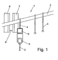
- a device 1 for grouping clothes hangers comprises a rail 2, which is arranged inclined to the horizontal and are hung on the hanger 3 and conveyed.
- the rail 2 has such a tendency that the hangers 3 can slide along the rail 2 due to gravity.
- an adapter hook 4 is provided in each case, which is used to group the hangers 3.
- the adapter hook 4 comprises a marking 6 for identification, for example a bar code.
- the adapter hook 4 may alternatively or additionally also have an RFID chip or other identification means.
- the adapter hook 4 further comprises a receptacle 5, to which one or more hangers 3 can be hung.
- a stopper element which has two spaced stops 7 and 8, between which a sensor for detecting the occupancy of the stopper element by an adapter hook 4 can be detected.
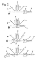
- An adapter hook 4 moves in the conveying direction along the rail and is followed by several hangers 3 (FIG. FIG. 2A ).
- the adapter hook 4 protrudes laterally in a direction perpendicular to the conveying direction over the hooks of the clothes hangers, which are usually formed by a wire section, and can thereby be stopped by the stops 7 and 8 of the stopper element, while the hangers 3 also stop at the stopper element when the stops 7 and 8 are closed can happen.
- the adapter hook 4 is stopped at the front first stop 7 and checked whether the position between the two stops 7 and 8 in the region of the sensor 9 is free. If this position is free, the stop 7 is moved away from the rail so that the adapter hook 4 can pass and is moved to the stop 8.
- the sensor 9 is located between the two stops 7 and 8 and can detect the occupation by the adapter hook 4, which causes the controller moves the front stop 7 in the closed position and the stopper 8 optionally with a certain Time delay opens.
- the adapter hook 4 By stopping the adapter hook 4, the following hangers 3 are accumulated and are now close behind the adapter hook. 4
- the adapter hook 4 may pass as shown in FIG Figure 2C you can see.
- the clothes hangers 3 arranged behind the adapter hook 4 have a narrow neck portion which is so thin that the stops 7 and 8 do not prevent movement of the hangers 3 even in the closed position. Rather, the hangers 3 can be further promoted together with the adapter hook 4 and moved as needed to a packaging station or other processing station. If a subsequent adapter hook 4 'follow the first adapter hook 4 with the hangers 3, this is now stopped by the first stop 7, which remains in the closed position as long as the sensor 9 occupancy by an adapter hook 4 detects and the stop 8 is still in the open position.
- the first stopper 7 can be opened ( FIG. 2D ). This avoids that a following adapter hook 4 'is accidentally moved to the first group of hangers 3 with the adapter hook 4.
- the adapter hook 4 'with the following hangers 3' is again stopped between the stops 7 and 8, to then be grouped with the following hangers 3 'and further processed.
- two separately movable stops 7 and 8 are provided, between which a sensor 9 is arranged.
- This embodiment has the advantage that a faulty grouping is reliably avoided.
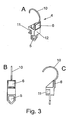
- the adapter hook 4 comprises an upper hook 10 which can be hung on a rail 2.
- the adapter hook 4 comprises a body 12 made of plastic, on which a coding 6, for example, a barcode is arranged for identification.
- an RFID chip can be provided in the body 12 made of plastic.
- a stop 11 is formed, which cooperates with the stops 7 and 8 of the stopper element.
- the wall section 11 projects laterally from a neck portion of the adapter hook 10 and has a greater width than the wire hanger following hangers.
- the adapter hook 4 further comprises a receptacle 5 in the form of an eyelet into which one or more clothes hooks can be hung.
Description
- Die vorliegende Erfindung betrifft ein Verfahren und eine Vorrichtung zum Gruppieren von Kleiderbügeln nach dem Oberbegriff der Ansprüche 1 und 3.
- Bei der Lagerung und Auslieferung von Textilien, insbesondere von Kleidungsstücken, ist es notwendig, Gruppen von Kleiderbügeln mit entsprechenden Kleidungsstücken zusammenzufassen, beispielsweise um eine bestimmte Kollektion an einen Händler auszuliefern. Um solche Gruppen von Kleiderbügeln zu bilden ist es bekannt, Trennbügel zwischen die Kleiderbügel vorzusehen, was gerade bei kleineren Gruppen von Kleiderbügeln die Förderkapazität nachteilig beeinflusst. Zudem kann es zu Fehlern bei der Gruppierung kommen, was nur mit viel Aufwand behoben werden kann.
- Die
EP 220 380 - Es ist daher Aufgabe der vorliegenden Erfindung ein Verfahren und eine Vorrichtung zum Gruppieren von Kleiderbügeln zu schaffen, die Fehler sicher vermeidet und eine hohe Förderkapazität besitzt.
- Diese Aufgabe wird mit einem Verfahren mit den Merkmalen des Anspruches 1 und einer Vorrichtung mit den Merkmalen des Anspruches 3 gelöst.
- Bei dem erfindungsgemäßen Verfahren wird ein Adapterhaken in einer Förderbewegung mittels eines Stopperelementes angehalten, wobei dann die Position des Adapterhakens über einen Sensor erfasst wird. Durch das Anhalten: des Adapterhakens werden nachfolgende Kleiderbügel an dem Adapterhaken aufgestaut und so gruppiert. Anschließend wird das Stopperelement geöffnet und wieder geschlossen, so dass der angehaltene Adapterhaken weiter in Förderrichtung bewegt wird und die aufgestauten Kleiderbügel zusammen mit dem Adapterhaken bewegt werden, wobei die Kleiderbügel auch in der geschlossenen Position des Stopperelementes an diesem vorbei gefördert werden, bis ein nachfolgender Adapterhaken durch das Stopperelement angehalten wird. Diese Vorgehensweise hat den Vorteil, dass durch das mechanische Anhalten eines Adapterhakens eine fehlerhafte Gruppierung vermieden wird. Denn der Adapterhaken übernimmt die Funktion eines Führungselementes, das die nachfolgenden Kleiderbügel gruppiert, bis ein weiterer Adapterhaken folgt. Dabei kann das Anhalten eines Adapterhakens solange erfolgen, bis eine nachfolgende Weiche oder andere Verarbeitungseinrichtung entsprechend angesteuert ist.
- Dabei kann auch eine große Förderkapazität erhalten werden, da der Adapterhaken selbst mit ein oder mehreren Kleiderbügeln belegt werden kann.
- Gemäß einer bevorzugten Ausgestaltung der Erfindung weist das Stopperelement zwei getrennt voneinander bewegbare Anschläge auf und der in Förderrichtung hintere Anschlag wird nur geöffnet, wenn der vordere Anschlag geschlossen ist. Dadurch wird sicher vermieden, dass selbst bei aufeinander folgenden Adapterhaken diese durch die Vorrichtung voneinander getrennt werden. Denn wenn der vordere Adapterhaken durch den hinteren Anschlag in Förderrichtung freigegeben wird, sorgt der vordere Anschlag für ein Anhalten des folgenden Adapterhakens.
- Die erfindungsgemäße Vorrichtung zum Gruppieren von Kleiderbügeln umfasst ein Stopperelement, mittels dem ein sich bewegender Adapterhaken angehalten werden kann, und ein Sensor zur Erfassung, ob ein Adapterhaken an dem Stopperelement gehalten ist. Das Stopperelement weist mindestens einen bewegbaren Anschlag auf, der in der geschlossenen Position einen Adapterhaken aufhält, aber hinter einem Adapterhaken sich ansammelnde Kleiderbügel passieren lässt. Dies wird dadurch erreicht, dass der Adapterhaken eine andere Form als die nachfolgenden Kleiderbügel aufweist und insofern ein mechanischer Anschlag den Adapterhaken zurückhält, aber die Kleiderbügel aufgrund einer schlankeren Geometrie passieren können. Dadurch kann mit einfachen Mitteln eine effektive Gruppierung der Kleiderbügel erfolgen, die durch die einzelnen Adapterhaken voneinander getrennt werden.
- Gemäß der Erfindung werden die Adapterhaken und Kleiderbügel entlang einer Schiene gefördert. Die Schiene kann beispielsweise schräg angeordnet sein, so dass eine Bewegung der Adapterhaken und Kleiderbügel durch die Schwerkraft erfolgt und keine gesonderten Antriebsmittel vorgesehen sein müssen.
- Der Adapterhaken umfasst eine Aufnahme zum Einhängen mundestens eines Kleiderbügels. Dadurch kann der Adapterhaken auch selbst zum Fördern von Kleiderbügeln verwendet werden, was die Förderkapazität optimiert.
- Um Fehler bei der Gruppierung der Kleiderbügel sicher zu vermeiden, kann das Stopperelement zwei getrennt voneinander bewegbare Anschläge aufweisen. Vorzugsweise ist dabei zwischen den Anschlägen der Sensor zur Erfassung der Belegung durch einen Adapterhaken vorgesehen, wobei der Platz zwischen den Anschlägen so ausgebildet ist, dass nur ein Adapterhaken eingefügt werden kann. Dann kann durch eine Steuerung sichergestellt sein, dass zumindest ein Anschlag immer in der geschlossenen Position verbleibt und direkt aufeinander folgende Adapterhaken durch die Vorrichtung ebenfalls voneinander getrennt werden.
- Der Adapterhaken weist vorzugsweise benachbe=art zu einem Haken einen Wandabschnitt auf, der mit dem mindestens einen Anschlag des Stopperelementes zusammenwirkt. Der Wandabschnitt kann dabei seitlich hervorstehen und breiter ausgebildet sein als der Hals eines Kleiderbügels, um auf sichere Weise eine Trennung zwischen Adapterhaken und Kleiderbügel vornehmen zu können.
- Gemäß einer weiteren Ausgestaltung umfasst der Adapterhaken mindestens eine Identifkationskennzeichnung, beispielsweise einen Barcorde oder einen RFID-Chip. Dadurch können Informationen zu den Kleidungsstücken an dem Adapterhaken und/oder der nachfolgenden Kleiderbügel gespeichert werden. Auch weitere Informationen wie Anzahl der Kleiderbügel etc. könnten abgespeichert werden, was über eine Steuerung für die Verarbeitung einer Gruppe von Kleiderbügeln zweckmäßig sein kann.
- Die Erfindung wird nachfolgend anhand eines Ausführungsbeispieles mit Bezug auf die beigefügten Zeichnungen näher erläutert. Es zeigen:
- Figur 1
- eine Ansicht einer erfindungsgemäßen Vorrichtung zum Gruppieren von Kleiderbügeln;
- Figuren 2 A bis 2D
- mehrere schematische Ansichten der Vorrichtung zum Gruppieren von Kleiderbügeln in unterschiedlichen Förderpositionen, und
- Figuren 3A bis 3C
- mehrere Ansichten eines Adapterhakens für die Vorrichtung der
Figur 1 - Eine Vorrichtung 1 zum Gruppieren von Kleiderbügeln umfasst eine Schiene 2, die zur Horizontalen geneigt angeordnet ist und an der Kleiderbügel 3 eingehängt und gefördert werden. Die Schiene 2 besitzt eine solche Neigung, dass die Kleiderbügel 3 aufgrund der Schwerkraft an der Schiene 2 entlang rutschen können. Zwischen den Kleiderbügeln 3 ist jeweils ein Adapterhaken 4 vorgesehen, der zum Gruppieren der Kleiderbügel 3 eingesetzt wird. Der Adapterhaken 4 umfasst eine Markierung 6 zur Identifikation, beispielsweise einen Barcode. Ferner kann der Adapterhaken 4 alternativ oder zusätzlich auch einen RFID-Chip oder andere Kennzeichnungsmittel besitzen. Der Adapterhaken 4 umfasst ferner eine Aufnahme 5, an der ein oder mehrere Kleiderbügel 3 eingehängt werden können.
- Um die Kleiderbügel 3 zu gruppieren ist ein Stopperelement vorgesehen, das zwei beabstandete Anschläge 7 und 8 aufweist, zwischen denen ein Sensor zur Erfassung der Belegung des Stopperelementes durch einen Adapterhaken 4 erfassbar ist.
- Das erfindungsgemäße Verfahren zum Gruppieren von Kleiderbügeln 3 wird mit Bezug auf die
Figuren 2A bis 2D näher erläutert. - Ein Adapterhaken 4 bewegt sich in Förderrichtung entlang der Schiene und ist gefolgt von mehreren Kleiderbügeln 3 (
Figur 2A ). Der Adapterhaken 4 steht in eine Richtung senkrecht zur Förderrichtung seitlich über die meist aus einem Drahtabschnitt gebildeten Haken der Kleiderbügel hervor und kann dadurch durch die Anschläge 7 und 8 des Stopperelementes angehalten werden, während die Kleiderbügel 3 auch bei geschlossenen Anschlägen 7 und 8 an dem Stopperlelement passieren können. - In einem ersten Schritt wird der Adapterhaken 4 an dem vorderen ersten Anschlag 7 angehalten und geprüft, ob die Position zwischen den beiden Anschlägen 7 und 8 im Bereich des Sensors 9 frei ist. Ist diese Position frei, wird der Anschlag 7 von der Schiene wegbewegt, so dass der Adapterhaken 4 passieren kann und bis zu dem Anschlag 8 bewegt wird.
- Wie in
Figur 2B zu sehen ist, befinde sich der Sensor 9 zwischen den beiden Anschlägen 7 und 8 und kann die Belegung durch den Adapterhaken 4 erfassen, was dazu führt, dass die Steuerung den vorderen Anschlag 7 in die geschlossene Position bewegt und den Anschlag 8 gegebenenfalls mit einer gewissen Zeitverzögerung öffnet. Durch das Anhalten des Adapterhakens 4 werden die nachfolgenden Kleiderbügel 3 angestaut und befinden sich nun dicht hinter dem Adapterhaken 4. - Wenn der zweite Anschlag 8 geöffnet wird, kann der Adapterhaken 4 passieren, wie dies in
Figur 2C zu sehen ist. Die hinter dem Adapterhaken 4 angeordneten Kleiderbügel 3 weisen einen schmalen Halsabschnitt auf, der so dünn ist, dass die Anschläge 7 und 8 selbst in der geschlossenen Position eine Bewegung der Kleiderbügel 3 nicht verhindern. Vielmehr können die Kleiderbügel 3 zusammen mit dem Adapterhaken 4 weiter gefördert werden und je nach Bedarf zu einer Verpackungsstation oder anderen Verarbeitungsstation bewegt werden. Sollte ein nachfolgender Adapterhaken 4' dem ersten Adapterhaken 4 mit den Kleiderbügeln 3 folgen, wird dieser nun durch den ersten Anschlag 7 aufgehalten, der solange in der geschlossenen Position bleibt, wie der Sensor 9 eine Belegung durch einen Adapterhaken 4 feststellt und der Anschlag 8 noch in der geöffneten Position ist. Erst wenn eine Belegung durch einen Adapterhaken 4 im Bereich des Sensors 9 nicht mehr vorliegt und der Anschlag 8 in der geschlossenen Position ist, kann der erste Anschlag 7 geöffnet werden (Figur 2D ). Dadurch wird vermieden, dass ein folgender Adapterhaken 4' versehentlich zu der ersten Gruppe von Kleiderbügeln 3 mit dem Adapterhaken 4 bewegt wird. Der Adapterhaken 4' mit den nachfolgenden Kleiderbügeln 3' wird wieder zwischen den Anschlägen 7 und 8 angehalten, um dann mit den folgenden Kleiderbügeln 3' gruppiert und weiterverarbeitet zu werden. - In dem dargestellten Ausführungsbeispiel sind zwei getrennt voneinander bewegbare Anschläge 7 und 8 vorgesehen, zwischen denen ein Sensor 9 angeordnet ist. Diese Ausgestaltung hat den Vorteil, dass eine fehlerhafte Gruppierung sicher vermieden wird. Es ist natürlich auch möglich, durch eine entsprechende Steuerung auch nur einen Anschlag zur Gruppierung von Kleiderbügeln einzusetzen.
- In den
Figuren 3A bis 3C ist der Adapterhaken 4 im Detail dargestellt. Der Adapterhaken 4 umfasst einen oberen Haken 10, der an einer Schiene 2 eingehängt werden kann. Statt einem dünnen Halsabschnitt umfasst der Adapterhaken 4 jedoch einen Körper 12 aus Kunststoff, an dem eine Codierung 6, beispielsweise ein Barcode zur Identifizierung angeordnet ist. Ferner kann in dem Körper 12 aus Kunststoff ein RFID-Chip vorgesehen sein. An dem Körper 12 aus Kunststoff ist ein Anschlag 11 ausgebildet, der mit den Anschlägen 7 und 8 des Stopperelementes zusammenwirkt. Der Wandabschnitt 11 steht dabei seitlich von einem Halsabschnitt des Adapterhakens 10 hervor und besitzt eine größere Breite als die Drahtbügel nachfolgender Kleiderbügel. - Der Adapterhaken 4 umfasst ferner eine Aufnahme 5 in Form einer Öse, in die ein oder mehrere Kleiderhaken eingehängt werden können. Dadurch kann die Förderkapazität der Vorrichtung zum Gruppieren von Kleiderbügeln optimiert werden.
Claims (7)
- Verfahren zum Gruppieren von Kleiderbügeln (3) mit den folgenden Schritten:- Anhalten eines Adapterhakens (4) in einer Förderbewegung mittels eines Stopperelementes (7, 8);- Erfassen einer Position des Adapterhakens (4);- Aufstauen nachfolgender Kleiderbügel (3) an dem Adapterhaken (4);- Öffnen und Schließen des Stopperelementes (7, 8) derart, dass der Adapterhaken (4) weiter in Förderrichtung bewegt wird, und- Fördern der aufgestauten Kleiderbügel (3) an dem geschlossenen Stopperelement (7, 8) vorbei, bis ein nachfolgender Adapterhaken (4) durch das Stopperelement (7, 8) angehalten wird.
- Verfahren nach Anspruch 1, dadurch gekennzeichnet, dass das Stopperelement zwei getrennt voneinander bewegbare Anschläge (7, 8) aufweist und der in Förderrichtung hintere Anschlag (8) nur geöffnet wird, wenn der vordere Anschlag (7) geschlossen ist.
- Vorrichtung zum Gruppieren von Kleiderbügeln, mit mehreren Adapterhaken (4), die eine Aufnahme (5) zum Einhängen mindestens eines Kleiderbügels (3) aufweisen, einer Schiene (2), entlang welcher die Adapterhaken (4) und die Kleiderbügel (5) gefördert werden, und einem Stopperelement (7, 8), welches mindestens einen bewegbaren Anschlag aufweist, mittels dem ein sich bewegender Adapterhaken (4) angehalten werden kann, und einem Sensor (9) zur Erfassung ob ein Adapterhaken (4) an dem Stopperelement (7, 8) gehalten ist, dadurch gekennzeichnet, daß der bewegbare Anschlag in der in der geschlossenen Position einen Adapterhaken (4) anhält, aber hinter einem Adapterhaken (4) sich ansammelnde Kleiderbügel (3) passieren lässt.
- Vorrichtung nach Anspruch 3, dadurch gekennzeichnet, dass das Stopperelement zwei getrennt voneinander bewegbare Anschläge (7, 8) aufweist.
- Vorrichtung nach Anspruch 4, dadurch gekennzeichnet, dass zwischen den Anschlägen (7, 8) der Sensor (9) zur Erfassung der Belegung durch einen Adapterhaken (4) vorgesehen ist.
- Vorrichtung nach einem der Ansprüche 3 bis 5, dadurch gekennzeichnet, dass der Adapterhaken (4) benachbart zu einem Haken (10) einen Wandabschnitt (11) aufweist, der mit dem mindestens einen Anschlag des Stopperelementes (7, 8) zusammenwirkt.
- Vorrichtung nach einem der Ansprüche 3 bis 6, dadurch gekennzeichnet, dass der Adapterhaken (4) eine Identifikationskennzeichnung aufweist.
Priority Applications (1)
| Application Number | Priority Date | Filing Date | Title |
|---|---|---|---|
| PL08167252T PL2070845T3 (pl) | 2007-12-10 | 2008-10-22 | Sposób i urządzenie do grupowania wieszaków do odzieży |
Applications Claiming Priority (1)
| Application Number | Priority Date | Filing Date | Title |
|---|---|---|---|
| DE102007059626A DE102007059626A1 (de) | 2007-12-10 | 2007-12-10 | Verfahren und Vorrichtung zum Gruppieren von Kleiderbügeln |
Publications (2)
| Publication Number | Publication Date |
|---|---|
| EP2070845A1 EP2070845A1 (de) | 2009-06-17 |
| EP2070845B1 true EP2070845B1 (de) | 2010-12-01 |
Family
ID=39967223
Family Applications (1)
| Application Number | Title | Priority Date | Filing Date |
|---|---|---|---|
| EP08167252A Active EP2070845B1 (de) | 2007-12-10 | 2008-10-22 | Verfahren und Vorrichtung zum Gruppieren von Kleiderbügeln |
Country Status (6)
| Country | Link |
|---|---|
| US (1) | US20090145868A1 (de) |
| EP (1) | EP2070845B1 (de) |
| AT (1) | ATE490205T1 (de) |
| DE (2) | DE102007059626A1 (de) |
| ES (1) | ES2357410T3 (de) |
| PL (1) | PL2070845T3 (de) |
Families Citing this family (3)
| Publication number | Priority date | Publication date | Assignee | Title |
|---|---|---|---|---|
| US8646855B2 (en) * | 2010-06-30 | 2014-02-11 | Carefusion 303, Inc. | Configurable cabinet for hanging and shelved items |
| US11647858B2 (en) * | 2020-06-23 | 2023-05-16 | Moshe Ratzabi | Inverted fit hanger |
| CN111776428B (zh) * | 2020-07-06 | 2021-11-16 | 伟成中港塑胶制品(惠州)有限公司 | 一种具有堆叠功能的衣架生产用送料装置 |
Family Cites Families (16)
| Publication number | Priority date | Publication date | Assignee | Title |
|---|---|---|---|---|
| US1926060A (en) * | 1931-04-24 | 1933-09-12 | American Can Co | Container loading apparatus |
| US2947407A (en) * | 1957-05-15 | 1960-08-02 | Byron A Wood | Conveyor mechanism for garments on hangers |
| US3620354A (en) * | 1970-04-27 | 1971-11-16 | Jerry N Mcmillan | Garment removal apparatus |
| SE376748B (de) * | 1973-10-09 | 1975-06-09 | Foerenade Fabriksverken | |
| EP0220380A2 (de) | 1985-07-05 | 1987-05-06 | Irving N. Arnold Associates, Ltd. | Datenspeicher- und Zugriffseinrichtung für Steuersysteme |
| US4991719A (en) * | 1989-03-03 | 1991-02-12 | Speed Sort, Inc. | Method and apparatus for sorting randomly positioned items minimizing sorting conveyor movement |
| US5377814A (en) * | 1990-06-20 | 1995-01-03 | Fabri-Check, Inc. | Transport carrier for use in an article sorting system |
| US6050421A (en) * | 1997-09-11 | 2000-04-18 | Jensen Usa, Inc. | Automatic laundry tie-off apparatus and method |
| DE29804038U1 (de) * | 1998-03-07 | 1998-05-20 | Pavel Gmbh Logistiksysteme Fue | Vereinzeler für auf Förderstrecken hängende Bügel, insbesondere Kleiderbügel mit Bekleidungsstücken |
| WO2000066280A2 (en) * | 1999-04-30 | 2000-11-09 | Siemens Electrocom, L.P. | Item singulation system |
| DE10026093A1 (de) * | 2000-05-26 | 2001-11-29 | Pavel Gmbh Logistiksysteme Fue | Hängeförderer zum Vereinzeln von Haken |
| US6799673B2 (en) * | 2001-10-12 | 2004-10-05 | Progressive Tool & Industries Co. | Versaroll overhead conveyor system |
| DK1476378T3 (da) * | 2002-02-22 | 2006-10-30 | Jensen Sweden Ab | Anordning for fremföring af genstande, så som kroge for töjböjler, system for transport og fremföring af töjböjler og fremgangsmåde for fremföring af sådanne genstande |
| US6959229B2 (en) * | 2003-03-07 | 2005-10-25 | Sdi Industries, Inc. | RFID control system |
| DE10359859A1 (de) * | 2003-12-18 | 2005-07-14 | PEP Fördertechnik GmbH | Adapterhaken für Fördersysteme und Beladestation für einen Adapterhaken |
| US7576655B2 (en) * | 2005-03-29 | 2009-08-18 | Accu-Sort Systems, Inc. | RFID conveyor system and method |
-
2007
- 2007-12-10 DE DE102007059626A patent/DE102007059626A1/de not_active Ceased
-
2008
- 2008-10-22 AT AT08167252T patent/ATE490205T1/de active
- 2008-10-22 DE DE502008001930T patent/DE502008001930D1/de active Active
- 2008-10-22 EP EP08167252A patent/EP2070845B1/de active Active
- 2008-10-22 PL PL08167252T patent/PL2070845T3/pl unknown
- 2008-10-22 ES ES08167252T patent/ES2357410T3/es active Active
- 2008-12-01 US US12/325,558 patent/US20090145868A1/en not_active Abandoned
Also Published As
| Publication number | Publication date |
|---|---|
| DE502008001930D1 (de) | 2011-01-13 |
| ATE490205T1 (de) | 2010-12-15 |
| US20090145868A1 (en) | 2009-06-11 |
| PL2070845T3 (pl) | 2011-06-30 |
| ES2357410T3 (es) | 2011-04-26 |
| EP2070845A1 (de) | 2009-06-17 |
| DE102007059626A1 (de) | 2009-06-18 |
Similar Documents
| Publication | Publication Date | Title |
|---|---|---|
| EP2789555B1 (de) | Verfahren zum auftragsorientierten Bereitstellen von Einzelwaren für mehrere Aufträge aus einem Warenlager | |
| EP2059467B1 (de) | Verfahren und vorrichtung zur vereinzelung von stückgut | |
| EP1927561B1 (de) | Vorrichtung und Verfahren zum Aufteilen eines Stroms von Gegenständen | |
| EP2886494B1 (de) | Fördervorrichtung zur Beförderung von hängenden Gegenständen | |
| EP3087877B1 (de) | Kassensystemanordnung mit warentrennstaberkennung | |
| EP3501995B1 (de) | Verfahren zur steuerung der parameter eines umreifungssystems | |
| EP2910498B1 (de) | Schaltbare Weiche zum Beeinflussen eines Flusses von Einzelwaren in einem Fördersystem, Fördersystem mit einer derartigen schaltbaren Weiche sowie Verfahren zum Schalten einer derartigen schaltbaren Weiche | |
| EP2899144A1 (de) | Fördervorrichtung und Verfahren zum automatisierten Fördern von Einzelwaren | |
| DE102017113818A1 (de) | Artikel-fördervorrichtung mit einem abschnitt zur vorübergehenden platzierung | |
| EP2923974B1 (de) | Vorrichtung und Verfahren zum platzsparenden Anordnen von Hängewaren | |
| EP2070845B1 (de) | Verfahren und Vorrichtung zum Gruppieren von Kleiderbügeln | |
| DE2831843C2 (de) | ||
| EP0737634A2 (de) | Verfahren zum Sortieren einer Mehrzahl einzeln geförderter Gegenstände | |
| EP4081354B1 (de) | Sortiervorrichtung und -verfahren | |
| EP3680384B1 (de) | Verfahren zur ermittlung der kürzeren und/oder längeren kante von wäschestücken und zum zuführen von wäschestücken zu einer wäschebehandlungseinrichtung | |
| EP3818001B1 (de) | Bügel-beladestation für hängeförderer | |
| DE19527819B9 (de) | Vereinzelungsvorrichtung für vorzugsweise merkmalsgekennzeichnete Trennbügel | |
| EP2108588A2 (de) | Verfahren und Vorrichtung zur Überprüfung von Greifelementen | |
| EP3106412B1 (de) | Gruppieren von gütern | |
| DE3007540A1 (de) | Vorrichtung zum pruefen und aussortieren von fremdflaschen | |
| DE102008046172B4 (de) | Vorrichtung und Verfahren zur Überwachung des Behältertransports bei einer Fördereinrichtung für Behälter und/oder Gebinde | |
| DE4010231C2 (de) | ||
| AT510369A2 (de) | Verfahren zur vereinzelung von stückgut | |
| DE4321958C2 (de) | Verfahren und Vorrichtung zum Verteilen von Stückgut | |
| EP3465365B1 (de) | Produktionsanlage zum herstellen einer vielzahl von artikeln und verfahren zum steuern und/oder überwachen der produktionsanlage |
Legal Events
| Date | Code | Title | Description |
|---|---|---|---|
| PUAI | Public reference made under article 153(3) epc to a published international application that has entered the european phase |
Free format text: ORIGINAL CODE: 0009012 |
|
| AK | Designated contracting states |
Kind code of ref document: A1 Designated state(s): AT BE BG CH CY CZ DE DK EE ES FI FR GB GR HR HU IE IS IT LI LT LU LV MC MT NL NO PL PT RO SE SI SK TR |
|
| AX | Request for extension of the european patent |
Extension state: AL BA MK RS |
|
| 17P | Request for examination filed |
Effective date: 20091014 |
|
| 17Q | First examination report despatched |
Effective date: 20091207 |
|
| AKX | Designation fees paid |
Designated state(s): AT BE BG CH CY CZ DE DK EE ES FI FR GB GR HR HU IE IS IT LI LT LU LV MC MT NL NO PL PT RO SE SI SK TR |
|
| GRAP | Despatch of communication of intention to grant a patent |
Free format text: ORIGINAL CODE: EPIDOSNIGR1 |
|
| GRAS | Grant fee paid |
Free format text: ORIGINAL CODE: EPIDOSNIGR3 |
|
| GRAA | (expected) grant |
Free format text: ORIGINAL CODE: 0009210 |
|
| AK | Designated contracting states |
Kind code of ref document: B1 Designated state(s): AT BE BG CH CY CZ DE DK EE ES FI FR GB GR HR HU IE IS IT LI LT LU LV MC MT NL NO PL PT RO SE SI SK TR |
|
| REG | Reference to a national code |
Ref country code: GB Ref legal event code: FG4D Free format text: NOT ENGLISH |
|
| REG | Reference to a national code |
Ref country code: CH Ref legal event code: EP |
|
| REG | Reference to a national code |
Ref country code: IE Ref legal event code: FG4D |
|
| REF | Corresponds to: |
Ref document number: 502008001930 Country of ref document: DE Date of ref document: 20110113 Kind code of ref document: P |
|
| REG | Reference to a national code |
Ref country code: NL Ref legal event code: T3 |
|
| REG | Reference to a national code |
Ref country code: SE Ref legal event code: TRGR |
|
| REG | Reference to a national code |
Ref country code: CH Ref legal event code: NV Representative=s name: ISLER & PEDRAZZINI AG |
|
| REG | Reference to a national code |
Ref country code: ES Ref legal event code: FG2A Ref document number: 2357410 Country of ref document: ES Kind code of ref document: T3 Effective date: 20110426 |
|
| PG25 | Lapsed in a contracting state [announced via postgrant information from national office to epo] |
Ref country code: NO Free format text: LAPSE BECAUSE OF FAILURE TO SUBMIT A TRANSLATION OF THE DESCRIPTION OR TO PAY THE FEE WITHIN THE PRESCRIBED TIME-LIMIT Effective date: 20110301 Ref country code: LT Free format text: LAPSE BECAUSE OF FAILURE TO SUBMIT A TRANSLATION OF THE DESCRIPTION OR TO PAY THE FEE WITHIN THE PRESCRIBED TIME-LIMIT Effective date: 20101201 |
|
| LTIE | Lt: invalidation of european patent or patent extension |
Effective date: 20101201 |
|
| PG25 | Lapsed in a contracting state [announced via postgrant information from national office to epo] |
Ref country code: HR Free format text: LAPSE BECAUSE OF FAILURE TO SUBMIT A TRANSLATION OF THE DESCRIPTION OR TO PAY THE FEE WITHIN THE PRESCRIBED TIME-LIMIT Effective date: 20101201 Ref country code: FI Free format text: LAPSE BECAUSE OF FAILURE TO SUBMIT A TRANSLATION OF THE DESCRIPTION OR TO PAY THE FEE WITHIN THE PRESCRIBED TIME-LIMIT Effective date: 20101201 Ref country code: SI Free format text: LAPSE BECAUSE OF FAILURE TO SUBMIT A TRANSLATION OF THE DESCRIPTION OR TO PAY THE FEE WITHIN THE PRESCRIBED TIME-LIMIT Effective date: 20101201 Ref country code: LV Free format text: LAPSE BECAUSE OF FAILURE TO SUBMIT A TRANSLATION OF THE DESCRIPTION OR TO PAY THE FEE WITHIN THE PRESCRIBED TIME-LIMIT Effective date: 20101201 Ref country code: CY Free format text: LAPSE BECAUSE OF FAILURE TO SUBMIT A TRANSLATION OF THE DESCRIPTION OR TO PAY THE FEE WITHIN THE PRESCRIBED TIME-LIMIT Effective date: 20101201 Ref country code: BG Free format text: LAPSE BECAUSE OF FAILURE TO SUBMIT A TRANSLATION OF THE DESCRIPTION OR TO PAY THE FEE WITHIN THE PRESCRIBED TIME-LIMIT Effective date: 20110301 |
|
| REG | Reference to a national code |
Ref country code: SK Ref legal event code: T3 Ref document number: E 8967 Country of ref document: SK |
|
| REG | Reference to a national code |
Ref country code: IE Ref legal event code: FD4D |
|
| PG25 | Lapsed in a contracting state [announced via postgrant information from national office to epo] |
Ref country code: GR Free format text: LAPSE BECAUSE OF FAILURE TO SUBMIT A TRANSLATION OF THE DESCRIPTION OR TO PAY THE FEE WITHIN THE PRESCRIBED TIME-LIMIT Effective date: 20110302 |
|
| REG | Reference to a national code |
Ref country code: PL Ref legal event code: T3 |
|
| PG25 | Lapsed in a contracting state [announced via postgrant information from national office to epo] |
Ref country code: IS Free format text: LAPSE BECAUSE OF FAILURE TO SUBMIT A TRANSLATION OF THE DESCRIPTION OR TO PAY THE FEE WITHIN THE PRESCRIBED TIME-LIMIT Effective date: 20110401 Ref country code: EE Free format text: LAPSE BECAUSE OF FAILURE TO SUBMIT A TRANSLATION OF THE DESCRIPTION OR TO PAY THE FEE WITHIN THE PRESCRIBED TIME-LIMIT Effective date: 20101201 Ref country code: PT Free format text: LAPSE BECAUSE OF FAILURE TO SUBMIT A TRANSLATION OF THE DESCRIPTION OR TO PAY THE FEE WITHIN THE PRESCRIBED TIME-LIMIT Effective date: 20110401 Ref country code: IE Free format text: LAPSE BECAUSE OF FAILURE TO SUBMIT A TRANSLATION OF THE DESCRIPTION OR TO PAY THE FEE WITHIN THE PRESCRIBED TIME-LIMIT Effective date: 20101201 |
|
| PG25 | Lapsed in a contracting state [announced via postgrant information from national office to epo] |
Ref country code: RO Free format text: LAPSE BECAUSE OF FAILURE TO SUBMIT A TRANSLATION OF THE DESCRIPTION OR TO PAY THE FEE WITHIN THE PRESCRIBED TIME-LIMIT Effective date: 20101201 |
|
| PLBE | No opposition filed within time limit |
Free format text: ORIGINAL CODE: 0009261 |
|
| STAA | Information on the status of an ep patent application or granted ep patent |
Free format text: STATUS: NO OPPOSITION FILED WITHIN TIME LIMIT |
|
| PG25 | Lapsed in a contracting state [announced via postgrant information from national office to epo] |
Ref country code: DK Free format text: LAPSE BECAUSE OF FAILURE TO SUBMIT A TRANSLATION OF THE DESCRIPTION OR TO PAY THE FEE WITHIN THE PRESCRIBED TIME-LIMIT Effective date: 20101201 |
|
| 26N | No opposition filed |
Effective date: 20110902 |
|
| REG | Reference to a national code |
Ref country code: DE Ref legal event code: R097 Ref document number: 502008001930 Country of ref document: DE Effective date: 20110902 |
|
| BERE | Be: lapsed |
Owner name: PEP FORDERTECHNIK G.M.B.H. Effective date: 20111031 |
|
| PG25 | Lapsed in a contracting state [announced via postgrant information from national office to epo] |
Ref country code: MC Free format text: LAPSE BECAUSE OF NON-PAYMENT OF DUE FEES Effective date: 20111031 |
|
| PG25 | Lapsed in a contracting state [announced via postgrant information from national office to epo] |
Ref country code: BE Free format text: LAPSE BECAUSE OF NON-PAYMENT OF DUE FEES Effective date: 20111031 |
|
| PG25 | Lapsed in a contracting state [announced via postgrant information from national office to epo] |
Ref country code: MT Free format text: LAPSE BECAUSE OF FAILURE TO SUBMIT A TRANSLATION OF THE DESCRIPTION OR TO PAY THE FEE WITHIN THE PRESCRIBED TIME-LIMIT Effective date: 20101201 |
|
| PG25 | Lapsed in a contracting state [announced via postgrant information from national office to epo] |
Ref country code: HU Free format text: LAPSE BECAUSE OF FAILURE TO SUBMIT A TRANSLATION OF THE DESCRIPTION OR TO PAY THE FEE WITHIN THE PRESCRIBED TIME-LIMIT Effective date: 20101201 |
|
| REG | Reference to a national code |
Ref country code: FR Ref legal event code: PLFP Year of fee payment: 8 |
|
| REG | Reference to a national code |
Ref country code: FR Ref legal event code: PLFP Year of fee payment: 9 |
|
| REG | Reference to a national code |
Ref country code: FR Ref legal event code: PLFP Year of fee payment: 10 |
|
| REG | Reference to a national code |
Ref country code: FR Ref legal event code: PLFP Year of fee payment: 11 |
|
| PGFP | Annual fee paid to national office [announced via postgrant information from national office to epo] |
Ref country code: LU Payment date: 20181019 Year of fee payment: 11 |
|
| PGFP | Annual fee paid to national office [announced via postgrant information from national office to epo] |
Ref country code: TR Payment date: 20181011 Year of fee payment: 11 Ref country code: FR Payment date: 20181022 Year of fee payment: 11 Ref country code: ES Payment date: 20181123 Year of fee payment: 11 Ref country code: CH Payment date: 20181019 Year of fee payment: 11 Ref country code: IT Payment date: 20181024 Year of fee payment: 11 Ref country code: GB Payment date: 20181019 Year of fee payment: 11 |
|
| PGFP | Annual fee paid to national office [announced via postgrant information from national office to epo] |
Ref country code: SK Payment date: 20190924 Year of fee payment: 12 |
|
| PGFP | Annual fee paid to national office [announced via postgrant information from national office to epo] |
Ref country code: PL Payment date: 20190923 Year of fee payment: 12 |
|
| PGFP | Annual fee paid to national office [announced via postgrant information from national office to epo] |
Ref country code: CZ Payment date: 20191021 Year of fee payment: 12 |
|
| REG | Reference to a national code |
Ref country code: NL Ref legal event code: HC Owner name: DEMATIC LOGISTICS GMBH; DE Free format text: DETAILS ASSIGNMENT: CHANGE OF OWNER(S), CHANGE OF OWNER(S) NAME; FORMER OWNER NAME: SDI GROUP GERMANY MATERIAL HANDLING SOLUTIONS GMBH Effective date: 20200310 |
|
| REG | Reference to a national code |
Ref country code: DE Ref legal event code: R081 Ref document number: 502008001930 Country of ref document: DE Owner name: DEMATIC LOGISTICS GMBH, DE Free format text: FORMER OWNER: PEP FOERDERTECHNIK GMBH, 33609 BIELEFELD, DE Ref country code: DE Ref legal event code: R082 Ref document number: 502008001930 Country of ref document: DE Representative=s name: PATENT- UND RECHTSANWAELTE LOESENBECK, SPECHT,, DE |
|
| REG | Reference to a national code |
Ref country code: CH Ref legal event code: PL |
|
| PG25 | Lapsed in a contracting state [announced via postgrant information from national office to epo] |
Ref country code: LI Free format text: LAPSE BECAUSE OF NON-PAYMENT OF DUE FEES Effective date: 20191031 Ref country code: LU Free format text: LAPSE BECAUSE OF NON-PAYMENT OF DUE FEES Effective date: 20191022 Ref country code: CH Free format text: LAPSE BECAUSE OF NON-PAYMENT OF DUE FEES Effective date: 20191031 |
|
| PG25 | Lapsed in a contracting state [announced via postgrant information from national office to epo] |
Ref country code: SE Free format text: LAPSE BECAUSE OF NON-PAYMENT OF DUE FEES Effective date: 20191023 |
|
| GBPC | Gb: european patent ceased through non-payment of renewal fee |
Effective date: 20191022 |
|
| REG | Reference to a national code |
Ref country code: AT Ref legal event code: PC Ref document number: 490205 Country of ref document: AT Kind code of ref document: T Owner name: DEMATIC LOGISTICS GMBH, DE Effective date: 20200831 |
|
| PG25 | Lapsed in a contracting state [announced via postgrant information from national office to epo] |
Ref country code: IT Free format text: LAPSE BECAUSE OF NON-PAYMENT OF DUE FEES Effective date: 20191022 Ref country code: GB Free format text: LAPSE BECAUSE OF NON-PAYMENT OF DUE FEES Effective date: 20191022 Ref country code: FR Free format text: LAPSE BECAUSE OF NON-PAYMENT OF DUE FEES Effective date: 20191031 |
|
| REG | Reference to a national code |
Ref country code: SK Ref legal event code: MM4A Ref document number: E 8967 Country of ref document: SK Effective date: 20201022 |
|
| PG25 | Lapsed in a contracting state [announced via postgrant information from national office to epo] |
Ref country code: CZ Free format text: LAPSE BECAUSE OF NON-PAYMENT OF DUE FEES Effective date: 20201022 Ref country code: SK Free format text: LAPSE BECAUSE OF NON-PAYMENT OF DUE FEES Effective date: 20201022 |
|
| PG25 | Lapsed in a contracting state [announced via postgrant information from national office to epo] |
Ref country code: ES Free format text: LAPSE BECAUSE OF NON-PAYMENT OF DUE FEES Effective date: 20191023 |
|
| PG25 | Lapsed in a contracting state [announced via postgrant information from national office to epo] |
Ref country code: TR Free format text: LAPSE BECAUSE OF NON-PAYMENT OF DUE FEES Effective date: 20191022 |
|
| PG25 | Lapsed in a contracting state [announced via postgrant information from national office to epo] |
Ref country code: PL Free format text: LAPSE BECAUSE OF NON-PAYMENT OF DUE FEES Effective date: 20201022 |
|
| PGFP | Annual fee paid to national office [announced via postgrant information from national office to epo] |
Ref country code: NL Payment date: 20231019 Year of fee payment: 16 |
|
| PGFP | Annual fee paid to national office [announced via postgrant information from national office to epo] |
Ref country code: DE Payment date: 20231020 Year of fee payment: 16 Ref country code: AT Payment date: 20231020 Year of fee payment: 16 |