EP2070648A2 - Förderbandmodul - Google Patents
Förderbandmodul Download PDFInfo
- Publication number
- EP2070648A2 EP2070648A2 EP08020774A EP08020774A EP2070648A2 EP 2070648 A2 EP2070648 A2 EP 2070648A2 EP 08020774 A EP08020774 A EP 08020774A EP 08020774 A EP08020774 A EP 08020774A EP 2070648 A2 EP2070648 A2 EP 2070648A2
- Authority
- EP
- European Patent Office
- Prior art keywords
- conveyor belt
- module
- module according
- conveyor
- belt module
- Prior art date
- Legal status (The legal status is an assumption and is not a legal conclusion. Google has not performed a legal analysis and makes no representation as to the accuracy of the status listed.)
- Granted
Links
Images

Classifications
-
- B—PERFORMING OPERATIONS; TRANSPORTING
- B23—MACHINE TOOLS; METAL-WORKING NOT OTHERWISE PROVIDED FOR
- B23Q—DETAILS, COMPONENTS, OR ACCESSORIES FOR MACHINE TOOLS, e.g. ARRANGEMENTS FOR COPYING OR CONTROLLING; MACHINE TOOLS IN GENERAL CHARACTERISED BY THE CONSTRUCTION OF PARTICULAR DETAILS OR COMPONENTS; COMBINATIONS OR ASSOCIATIONS OF METAL-WORKING MACHINES, NOT DIRECTED TO A PARTICULAR RESULT
- B23Q7/00—Arrangements for handling work specially combined with or arranged in, or specially adapted for use in connection with, machine tools, e.g. for conveying, loading, positioning, discharging, sorting
- B23Q7/14—Arrangements for handling work specially combined with or arranged in, or specially adapted for use in connection with, machine tools, e.g. for conveying, loading, positioning, discharging, sorting co-ordinated in production lines
- B23Q7/1426—Arrangements for handling work specially combined with or arranged in, or specially adapted for use in connection with, machine tools, e.g. for conveying, loading, positioning, discharging, sorting co-ordinated in production lines with work holders not rigidly fixed to the transport devices
- B23Q7/1447—Arrangements for handling work specially combined with or arranged in, or specially adapted for use in connection with, machine tools, e.g. for conveying, loading, positioning, discharging, sorting co-ordinated in production lines with work holders not rigidly fixed to the transport devices using endless conveyors
-
- B—PERFORMING OPERATIONS; TRANSPORTING
- B65—CONVEYING; PACKING; STORING; HANDLING THIN OR FILAMENTARY MATERIAL
- B65G—TRANSPORT OR STORAGE DEVICES, e.g. CONVEYORS FOR LOADING OR TIPPING, SHOP CONVEYOR SYSTEMS OR PNEUMATIC TUBE CONVEYORS
- B65G43/00—Control devices, e.g. for safety, warning or fault-correcting
- B65G43/08—Control devices operated by article or material being fed, conveyed or discharged
-
- B—PERFORMING OPERATIONS; TRANSPORTING
- B65—CONVEYING; PACKING; STORING; HANDLING THIN OR FILAMENTARY MATERIAL
- B65G—TRANSPORT OR STORAGE DEVICES, e.g. CONVEYORS FOR LOADING OR TIPPING, SHOP CONVEYOR SYSTEMS OR PNEUMATIC TUBE CONVEYORS
- B65G2207/00—Indexing codes relating to constructional details, configuration and additional features of a handling device, e.g. Conveyors
- B65G2207/30—Modular constructions
Definitions
- the present invention relates to a conveyor belt module for installation in a conveyor system or a production line, in particular for installation in a modular production line, as described in the European patent application with the file reference EP 07 12 3174 the same applicant is described. The priority of this application is claimed and express reference is made to the content of this application. Production lines with conveyor belts are used today in almost all branches of industry, especially in the electronics and automotive industries, but also in watchmaking.
- a multiplicity of conveyor belt sections are usually used, which are assembled to form a conveyor belt.
- the individual conveyor belt sections run around rotatable guide rollers, of which at least one is driven in each case.
- additional assembly units, feeding units for feeding parts, sensors and in most cases a central control are provided and cooperate with the conveyor belts.
- the present invention is therefore based on the object to provide a way that allows a quick and easy replacement of a conveyor belt section.
- the conveyor belt module has a body on which at least one deflection roller and a further deflection element are rotatably mounted, about which a conveyor belt is guided, and a drive for driving at least the guide roller.
- the drive is arranged in the body.
- the module also has mechanical and electrical connection elements for connecting the module to a conveyor system, as well as at least one sensor.
- the sensor is arranged under the conveyor belt in such a way that objects which are transported on the conveyor belt can be detected with the aid of the sensor.
- the mechanical and electrical connection elements can be, for example, sockets into which suitable electrical connectors can be inserted.
- These modules can supply power to the module and control signals from an external controller to the conveyor module. At the same time, the signals detected by the sensor integrated in the module can be given to an external controller.
- the entire module can be replaced in a few simple steps. It is sufficient to separate the mechanical and electrical connections made via the connecting elements, to take out the module, to insert a new module, and to re-establish the connections with the new module.
- the production line does not necessarily have to be stopped.
- the module removed from the production line can now be repaired without time pressure.
- a worn conveyor belt can be dismantled and replaced by a new conveyor belt.
- the conveyor belt module comprises a plurality of sensors.
- the sensors is an RFID reader.
- RFID transponders can be attached, in which the production related data are stored. This data can be read by the RFID reader and passed on to an external control unit which, depending on these data, can issue a corresponding command to the conveyor belt module or to a switch or production unit located after or above the conveyor belt module.
- a writing unit which can modify data stored in a memory connected to a workpiece carrier, can be integrated in the conveyor belt module.
- the deflection shaft is clamped on both sides laterally outside the conveyor belt firmly in the body, and on the guide shaft a plurality of spaced slide bushings are rotatably mounted, wherein the guide shaft is supported by engaging between the slide bushes supporting elements.
- a deflection of a conveyor belt is already in the German patent application with the file number 10 2006 038 185.8 known, which is hereby incorporated by reference.
- the deflection described in this document via a deflection shaft with rotatably mounted sliding bushes and supporting elements located therebetween makes it possible to keep the radius of the deflection very small, and still obtain a little prone to wear and robust deflection.
- the sliding bushes can consist of plain bearing plastic, of a coated with PTFE and / or graphite metal or sintered bronze.
- the conveyor belt module has at least two further guide rollers, around which a second conveyor belt is guided, which is substantially parallel to the conveyor belt first conveyor belt runs.
- a separate drive is preferably provided for each of the two conveyor belts.
- both the first drive and the optional second drive can be a simple drive motor which drives the conveyor belt at a constant speed. But it is also possible to provide a drive with variable speed and / or with two possible drive directions. If two parallel conveyor belts are provided, they are preferably driven in opposite directions.
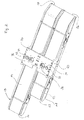
- Fig. 1 shows a conveyor belt module for installation in a modular production line in a perspective view from above.
- the conveyor belt module has a body 10 which is bounded longitudinally by side walls 11, 13. That in the Fig. 1 and 2 shown conveyor belt module is two lanes, that is, it has two parallel to each other and to the side walls 11, 13 extending conveyor belts 12, 14th
- Fig. 1 By way of example, three workpiece carriers 50 are shown, which essentially have the shape of plates with a frame surrounding a rectangular base, and which are conveyed on the conveyor belts 12, 14. Each of the two conveyor belts 12, 14 is just wide enough for a workpiece carrier 50. On the outer sides of the conveyor belts 12, 14 are in the conveying direction F1, F2 limiting webs 16 (for the band 12) and 18 (for the band 14) as a guide for the workpiece carrier 50.
- the right or rear conveyor belt 14 is longer than the front or left conveyor belt 12. While the two conveyor belts 12, 14 on the in Fig. 1 left side transverse to their conveying directions F1, F2 flush with each other, is the longer conveyor belt 14 on the other side over the shorter conveyor belt 12 via.
- two equal length conveyor belts or any other arrangement of two different length conveyor belts can be selected in a two-lane conveyor belt module.
- Both conveyor belts 12, 14 are each on one side (in Fig. 1 right) guided around a guide roller 22, 24 which is rotatably mounted on the body 10.
- both conveyor belts 12, 14 each about a compared to the guide rollers 22, 24 very thin guide shaft 26, 28 with rotatably mounted sliding bushes (not visible in the figures) out, so that a transfer tongue 20 and, 21 is formed.
- the deflection shafts 26, 28 themselves are not rotatably mounted on the body 10, but firmly clamped in the body 10. More precisely, the guide shaft 26, around which the first conveyor belt 12 is guided, is clamped between the left side wall 11 of the body and an intermediate wall, while the guide shaft 28 around which the second conveyor belt 14 is guided, between the right side wall 13 of the body and a Partition sits.
- On the deflection shafts 26, 28 are each more movably mounted sliding bushes spaced apart.
- the guide rollers 22, 24 are each driven by a drive, not shown in the figures, which is housed in the body 10.
- this is an electric motor with suitable power transmission means.
- the two conveyor belts 12, 14 are operated with opposite flow directions.
- the drive can be designed so that it allows a change of direction.
- Fig. 1 Also integrated into the conveyor belt module are at least two RFID read heads not shown in the figures.
- Fig. 1 are the areas below which the two read heads are designated by the reference numeral 44. It can be seen that in each case one reading head comes to lie below each conveyor belt 12, 14, so that an RFID transponder attached to a workpiece carrier 50 can be read out when the workpiece carrier 50 on one of the conveyor belts 12, 14 passes the reading head underneath.
- other sensors can be integrated into the conveyor belt module, for example, inductive or capacitive sensors, light sensors, etc.
- Fig. 2 shows that in Fig. 1 shown conveyor belt module from another perspective, namely from below, and it can be seen a connection plate 30 which extends across both conveyor belts 12, 14 from a side wall 11 of the body 10 to the other 13.
- connection plate 30 which extends across both conveyor belts 12, 14 from a side wall 11 of the body 10 to the other 13.
- various connecting elements 32, 34, 36 are provided, via which the conveyor belt module can be connected to a conveyor system or a production line.
- similar modules or other elements of a production line serve connecting pins 32 and centering bushings 34.
- electrical plug contacts 36 are provided which are suitable both for connection to a network and for power supply, for example, for the drive, can serve.
- the conveyor module can thus be powered from the outside, and can exchange information and control signals via a network with other elements of a production line or with an external controller.
Landscapes
- Engineering & Computer Science (AREA)
- Mechanical Engineering (AREA)
- Control Of Conveyors (AREA)
- Structure Of Belt Conveyors (AREA)
- Rollers For Roller Conveyors For Transfer (AREA)
Abstract
Description
- Die vorliegende Erfindung betrifft ein Förderbandmodul zum Einbau in ein Fördersystem oder eine Fertigungslinie, insbesondere zum Einbau in eine modulare Fertigungslinie, wie sie in der Europäischen Patentanmeldung mit dem Aktenzeichen
EP 07 12 3174 - In einer Fertigungslinie wird dabei üblicherweise eine Vielzahl von Förderbandabschnitten verwendet, die zu einem Förderband zusammengesetzt werden. Die einzelnen Förderbandabschnitte laufen um drehbare Umlenkwalzen, von denen jeweils mindestens eine angetrieben ist. Je nach Art der Produktionslinie sind zusätzlich Montageinheiten, Zuführeinheiten zum Zuführen von Teilen, Sensoren und in den meisten Fällen eine zentrale Steuerung vorgesehen und wirken mit den Förderbändern zusammen.
- Förderbänder müssen aufgrund von Verschleisserscheinungen regelmässig ausgetauscht werden. Dies ist bei herkömmlichen Produktionslinien sehr aufwändig. Meist muss die gesamte Produktionslinie angehalten werden, damit das Förderband ausgetauscht werden kann.
- Der vorliegenden Erfindung liegt daher die Aufgabe zugrunde, eine Möglichkeit bereitzustellen, die einen schnellen und einfachen Austausch eines Förderbandabschnittes ermöglicht.
- Diese Aufgabe wird erfindungsgemäss durch ein Förderbandmodul gemäss Anspruch 1 gelöst.
- Das Förderbandmodul besitzt einen Korpus, an dem wenigstens eine Umlenkwalze und ein weiteres Umlenkelement drehbar gelagert sind, um welche ein Förderband geführt ist, sowie einen Antrieb zum Antreiben wenigstens der Umlenkwalze. Der Antrieb ist in dem Korpus angeordnet. Das Modul besitzt ferner mechanische und elektrische Verbindungselemente zum Verbinden des Moduls mit einem Fördersystem, sowie wenigstens einen Sensor. Der Sensor ist dabei derart unter dem Förderband angeordnet, dass Objekte, die auf dem Förderband transportiert werden, mit Hilfe des Sensors erfasst werden können.
- Die mechanischen und elektrischen Verbindungselemente können beispielsweise Buchsen sein, in die passende elektrische Steckverbinder eingesteckt werden können. Über diese Verbindungselemente kann das Modul mit Strom versorgt werden, und es können Steuersignale von einer externen Steuerung an das Förderbandmodul gegeben werden. Gleichzeitig können die von dem in das Modul integrierten Sensor erfassten Signale an eine externe Steuerung gegeben werden.
- Wenn das Förderband oder auch ein anderer Bestandteil des Moduls ausgetauscht werden muss, kann das gesamte Modul mit wenigen Handgriffen ausgewechselt werden. Es genügt, die über die Verbindungselemente hergestellten mechanischen und elektrischen Verbindungen zu trennen, das Modul herauszunehmen, ein neues Modul einzusetzen, und die Verbindungen mit dem neuen Modul erneut herzustellen. Dabei muss die Produktionslinie nicht notwendigerweise angehalten werden.
- Das aus der Produktionslinie entfernte Modul kann nun ohne Zeitdruck repariert werden. beispielsweise kann ein verschlissenes Förderband demontiert und durch ein neues Förderband ersetzt werden.
- Gemäss einer bevorzugten Ausführungsform der Erfindung umfasst das Förderbandmodul mehrere Sensoren. Dabei ist vorzugsweise wenigstens einer der Sensoren ein RFID-Leser. An den Werkstückträgern oder auch den Werkstücken selbst können RFID-Transponder angebracht werden, in denen die Fertigung betreffende Daten abgespeichert sind. Diese Daten kann der RFID-Leser auslesen und an eine externe Steuereinheit weitergeben, die in Abhängigkeit von diesen Daten dem Förderbandmodul oder einer nach dem oder oberhalb des Förderbandmoduls liegende Weiche oder Fertigungseinheit einen entsprechenden Befehl erteilen kann.
- Ebenso kann im Übrigen in das Förderbandmodul eine Schreibeinheit integriert sein, welche Daten modifizieren kann, die in einem mit einem Werkstückträger verbundenen Speicher gespeichert sind.
- Gemäss einer bevorzugten Ausführungsform der Erfindung ist die Umlenkwelle beidseitig seitlich ausserhalb des Transportbandes fest in den Korpus eingespannt, und auf der Umlenkwelle sind mehrere voneinander beabstandete Gleitbuchsen drehbar gelagert, wobei die Umlenkwelle über zwischen den Gleitbuchsen eingreifende Abstützelemente abgestützt ist. Eine derartige Umlenkung eines Förderbandes ist bereits aus der Deutschen Patentanmeldung mit dem Aktenzeichen
10 2006 038 185.8 bekannt, auf die hiermit ausdrücklich Bezug genommen wird. Die in diesem Dokument beschriebene Umlenkung über eine Umlenkwelle mit drehbar gelagerten Gleitbuchsen und dazwischen liegenden Abstützelementen erlaubt es, den Radius der Umlenkung sehr klein zu halten, und dennoch eine wenig verschleissanfällige und robuste Umlenkung zu erhalten. - Die Gleitbuchsen können dabei aus Gleitlagerkunststoff, aus einem mit PTFE und/oder Graphit beschichteten Metall oder aus Sinterbronze bestehen.
- Gemäss einer bevorzugten Ausführungsform der Erfindung weist das Förderbandmodul wenigstens zwei weitere Umlenkwalzen auf, um die ein zweites Förderband geführt ist, welches im Wesentlichen parallel zu dem ersten Förderband verläuft. Man erhält damit ein zweispuriges Förderbandmodul, was für gewisse Anwendungen von Vorteil ist. Dabei ist vorzugsweise für jedes der beiden Förderbänder ein separater Antrieb vorgesehen. Im Prinzip ist es jedoch auch denkbar, beide Förderbänder über einen gemeinsamen Antrieb anzutreiben, wobei dann gegebenenfalls Kupplungselemente vorgesehen werden können, die es ermöglichen, unterschiedliche Antriebsrichtungen oder unterschiedliche Bandgeschwindigkeiten für die beiden Bänder vorzusehen.
- Im Prinzip kann es sich im Übrigen sowohl bei dem ersten Antrieb als auch bei dem optionalen zweiten Antrieb um einen einfachen Antriebsmotor handeln, der das Transportband mit konstanter Geschwindigkeit antreibt. Es ist aber auch möglich, einen Antrieb mit variabler Geschwindigkeit und/oder mit zwei möglichen Antriebsrichtungen vorzusehen. Wenn zwei parallele Förderbänder vorgesehen sind, werden diese vorzugsweise in einander entgegen gesetzte Richtungen angetrieben.
- Im Folgenden soll die Erfindung anhand eines bevorzugten Ausführungsbeispiels und unter Bezugnahme auf die beigefügten Zeichnungen näher beschrieben werden.
Dabei zeigen die Zeichnungen im Einzelnen: -
Fig. 1 : eine perspektivische Ansicht eines Förderbandmoduls von oben, -
Fig. 2 : eine perspektivische Ansicht des Förderbandmoduls ausFig. 1 von unten. -
Fig. 1 zeigt ein Förderbandmodul zum Einbau in eine modulare Fertigungslinie in einer perspektivischen Ansicht von oben. Das Förderbandmodul besitzt einen Korpus 10, der in Längsrichtung von Seitenwänden 11, 13 begrenzt ist. Das in denFig. 1 und2 dargestellte Förderbandmodul ist zweispurig, das heisst es besitzt zwei parallel zueinander und zu den Seitenwänden 11, 13 verlaufende Förderbänder 12, 14. - In der
Fig. 1 sind beispielhaft drei Werkstückträger 50 dargestellt, die im Wesentlichen die Form von Tellern mit einem eine rechteckige Grundfläche umgebenden Rahmen besitzen, und die auf den Förderbändern 12, 14 befördert werden. Jedes der beiden Förderbänder 12, 14 ist gerade breit genug für einen Werkstückträger 50. An den Aussenseiten der Förderbänder 12, 14 dienen sich in Förderrichtung F1, F2 Begrenzungsstege 16 (für das Band 12) bzw. 18 (für das Band 14) als Führung für die Werkstückträger 50. - Das in
Fig. 1 rechts bzw. hinten liegende Förderband 14 ist länger als das vorne bzw. links liegende Förderband 12. Während die beiden Förderbänder 12, 14 auf der inFig. 1 links liegenden Seite quer zu ihren Förderrichtungen F1, F2 bündig miteinander abschliessen, steht das längere Förderband 14 auf der anderen Seite über das kürzere Förderband 12 über. Selbstverständlich können bei einem zweispurigen Förderbandmodul auch zwei gleich lange Förderbänder oder eine beliebige andere Anordnung zweier unterschiedlich langer Förderbänder gewählt werden. - Beide Förderbänder 12, 14 sind jeweils an einer Seite (in
Fig. 1 rechts) um eine Umlenkwalze 22, 24 geführt, die drehbar an dem Korpus 10 gelagert ist. - Auf der anderen Seite (in
Fig. 1 links) sind beide Förderbänder 12, 14 jeweils um eine im Vergleich zu den Umlenkwalzen 22, 24 sehr dünne Umlenkwelle 26, 28 mit darauf drehbar gelagerten Gleitbuchsen (in den Figuren nicht sichtbar) geführt, so dass eine Übergabezunge 20 bzw, 21 gebildet wird. Die Umlenkwellen 26, 28 selbst sind nicht drehbar an dem Korpus 10 gelagert, sondern fest in den Korpus 10 eingespannt. Genauer ist die Umlenkwelle 26, um die das erste Förderband 12 geführt ist, zwischen der linken Seitenwand 11 des Korpus und einer Zwischenwand eingespannt, während die Umlenkwelle 28, um die das zweite Förderband 14 geführt ist, zwischen der rechten Seitenwand 13 des Korpus und einer Zwischenwand sitzt. Auf den Umlenkwellen 26, 28 sind jeweils mehrere voneinander beabstandete Gleitbuchsen beweglich gelagert. Zwischen den in den Figuren nicht dargestellten Gleitbuchsen sind ebenfalls in den Figuren nicht dargestellte Abstützelemente vorgesehen, die dafür sorgen, dass sich die dünnen Umlenkwellen 26, 28 nicht durchbiegen. Diese Art der Umlenkung ist in der oben bereits erwähnten deutschen Patentanmeldung vom 14. August 2006 mit dem Aktenzeichen10 2006 038 185.8 der IWB Industrietechnik GmbH genauer beschrieben, auf die die vorliegende Anmeldung Bezug nimmt. Durch den kleinen Radius der abgestützten Umlenkwelle können auch kleine Teile von einem weiteren Förderbandmodul an das hier dargestellte Modul übergeben werden, ohne in einen Zwischenraum zwischen den Umlenkpunkten der jeweiligen Förderbänder zu fallen. - Die Umlenkwalzen 22, 24 werden jeweils von einem in den Figuren nicht dargestellten Antrieb angetrieben, der in dem Korpus 10 untergebracht ist. Vorzugsweise handelt es sich dabei um einen Elektromotor mit geeigneten Kraftübertragungsmitteln. Wie in
Fig. 1 durch die beiden Pfeile F1, F2 angedeutet, werden die beiden Förderbänder 12, 14 mit einander entgegen gesetzten Förderrichtungen betrieben. Der Antrieb kann jedoch so ausgebildet sein, dass er einen Richtungswechsel ermöglicht. - In das Förderbandmodul integriert sind zudem wenigstens zwei in den Figuren nicht dargestellte RFID - Leseköpfe. In
Fig. 1 sind die Bereiche, unterhalb derer die beiden Leseköpfe liegen, mit der Bezugsziffer 44 bezeichnet. Man sieht, dass jeweils ein Lesekopf unter jedem Förderband 12, 14 zu liegen kommt, sodass ein an einem Werkstückträger 50 befestigter RFID - Transponder ausgelesen werden kann, wenn der Werkstückträger 50 auf einem der Förderbänder 12, 14 den darunter liegenden Lesekopf passiert. Zusätzlich, oder auch an Stelle der RFID-Leseköpfe, können auch andere Sensoren in das Förderbandmodul integriert werden, beispielsweise induktive oder kapazitive Sensoren, Lichtsensoren etc.) -
Fig. 2 zeigt das inFig. 1 dargestellte Förderbandmodul aus einer anderen Perspektive, nämlich von unten, und man erkennt eine Anschlussplatte 30, die sich quer über beide Förderbänder 12, 14 von einer Seitenwand 11 des Korpus 10 bis zur anderen 13 erstreckt. An dieser Anschlussplatte sind verschiedene Verbindungselemente 32, 34, 36 vorgesehen, über welche das Förderbandmodul an ein Fördersystem oder eine Fertigungslinie angeschlossen werden kann. Zum Herstellen einer mechanischen Verbindung und zur korrekten Ausrichtung des Moduls in Bezug auf andere, gleichartige Module oder sonstige Elemente einer Fertigungslinie dienen Verbindungsstifte 32 sowie Zentrierbuchsen 34. Darüber hinaus sind elektrische Steckkontakte 36 vorgesehen, die sowohl zur Anbindung an ein Netzwerk als auch zur Energieversorgung, beispielsweise für den Antrieb, dienen können. - Das Förderbandmodul kann somit von aussen mit Energie versorgt werden, und kann über ein Netzwerk mit anderen Elementen einer Fertigungslinie oder mit einer externen Steuerung Informationen und Steuersignale austauschen.
- Es sei darauf hingewiesen, dass das in den Figuren gezeigte Ausführungsbeispiel der Erfindung lediglich zur Veranschaulichung der in den Patentansprüchen definierten Erfindung dient, und keinesfalls einschränkend zu verstehen ist. Insbesondere ist es keineswegs notwendig, dass das erfindungsgemässe Förderbandmodul zwei Förderbänder umfasst. Ein Modul mit nur einem Förderband, welches um eine Umlenkwalze und ein weiteres Umlenkelement, wie z.B. die oben beschriebenen dünnen Umlenkwelle, geführt ist, ist ebenfalls von der Erfindung umfasst.
-
- 10
- Korpus
- 11
- Seitenwand des Korpus
- 12
- Förderband
- 13
- Seitenwand des Korpus
- 14
- Förderband
- 16
- Begrenzungssteg
- 18
- Begrenzungssteg
- 20
- Übergabezunge
- 21
- Übergabezunge
- 22
- Umlenkwalze
- 24
- Umlenkwalze
- 26
- Umlenkwelle
- 28
- Umlenkwelle
- 30
- Anschlussplatte
- 32
- Verbindungsstift
- 34
- Zentrierbuchse
- 36
- elektrischer Steckkontakt
- 44
- Ort, unter dem Sensor angeordnet ist
- 50
- Werkstückträger
- F1
- Förderrichtung
- F2
- Förderrichtung
Claims (7)
- Förderbandmodul mit einem Korpus (10), an dem wenigstens eine Umlenkwalze (22) und ein weiteres Umlenkelement (26) drehbar gelagert sind, um welche ein Förderband (12) geführt ist, sowie einem Antrieb zum Antreiben wenigstens der Umlenkwalze (22), der in dem Korpus (10) angeordnet ist, wobei das Modul ferner mechanische und elektrische Verbindungselemente (32, 34, 36) zum Verbinden des Moduls mit einem Fördersystem oder einer Fertigungslinie, sowie wenigstens einen Sensor umfasst, welcher derart unter dem Förderband (12) angeordnet ist, dass auf dem Förderband transportiert werdende Objekte (50) mit Hilfe des Sensors erfassbar sind.
- Förderbandmodul nach Anspruch 1,
dadurch gekennzeichnet, dass es mehrere Sensoren, insbesondere wenigstens einen RFID-Leser und/oder wenigstens einen anderen Sensor umfasst. - Förderbandmodul nach Anspruch 2,
dadurch gekennzeichnet, dass das Förderband (12) auf wenigstens einer Seite des Moduls eine im Vergleich zu einem Durchmesser der Umlenkwalzen (22) dünne Umlenkwelle (26) umschlingt, um eine Übergabezunge (20) zu bilden. - Förderbandmodul nach Anspruch 3,
dadurch gekennzeichnet, dass die Umlenkwelle (26) beidseitig seitlich ausserhalb des Förderbandes (12) fest in den Korpus (10) eingespannt ist, und auf der Umlenkwelle (26) mehrere voneinander beabstandete Gleitbuchsen drehbar gelagert sind, wobei die Umlenkwelle (26) über zwischen den Gleitbuchsen eingreifende Abstützelemente abgestützt ist. - Förderbandmodul nach Anspruch 4,
dadurch gekennzeichnet, dass die Gleitbuchsen aus Gleitlagerkunststoff, aus einem mit PTFE und/oder Graphit beschichteten Metall oder aus Sinterbronze bestehen. - Förderbandmodul nach einem der vorstehenden Ansprüche,
dadurch gekennzeichnet, dass es wenigstens eine zweite Umlenkwalze (24) und ein zweites weiteres Umlenkelement (28) aufweist, um die ein zweites Förderband (14) geführt ist, welches im Wesentlichen parallel zu dem ersten Förderband (12) verläuft. - Förderbandmodul nach Anspruch 6,
dadurch gekennzeichnet, dass es einen zweiten Antrieb zum Antreiben wenigstens der Umlenkwalze (24) des zweiten Förderbandes (14) aufweist
Priority Applications (4)
| Application Number | Priority Date | Filing Date | Title |
|---|---|---|---|
| EP08020774A EP2070648B1 (de) | 2007-12-13 | 2008-11-28 | Förderbandmodul |
| JP2009266951A JP2010126367A (ja) | 2008-11-28 | 2009-11-25 | コンベア・ベルト・モジュール |
| CN200910224854A CN101746589A (zh) | 2008-11-28 | 2009-11-27 | 传送带模块 |
| US12/627,158 US20100133069A1 (en) | 2007-12-13 | 2009-11-30 | Conveyor belt module |
Applications Claiming Priority (3)
| Application Number | Priority Date | Filing Date | Title |
|---|---|---|---|
| EP07123174A EP2070647B1 (de) | 2007-12-13 | 2007-12-13 | Modulare Fertigungslinie |
| EP07123171A EP2070847B1 (de) | 2007-12-13 | 2007-12-13 | Weiche für Förderer |
| EP08020774A EP2070648B1 (de) | 2007-12-13 | 2008-11-28 | Förderbandmodul |
Publications (3)
| Publication Number | Publication Date |
|---|---|
| EP2070648A2 true EP2070648A2 (de) | 2009-06-17 |
| EP2070648A3 EP2070648A3 (de) | 2009-10-07 |
| EP2070648B1 EP2070648B1 (de) | 2011-06-08 |
Family
ID=40473651
Family Applications (1)
| Application Number | Title | Priority Date | Filing Date |
|---|---|---|---|
| EP08020774A Active EP2070648B1 (de) | 2007-12-13 | 2008-11-28 | Förderbandmodul |
Country Status (3)
| Country | Link |
|---|---|
| US (1) | US20100133069A1 (de) |
| EP (1) | EP2070648B1 (de) |
| AT (1) | ATE511942T1 (de) |
Cited By (3)
| Publication number | Priority date | Publication date | Assignee | Title |
|---|---|---|---|---|
| DE102009033183A1 (de) * | 2009-07-13 | 2011-01-27 | Ief Werner Gmbh | Transportsystem für eine Produktionsanlage |
| CN103495549A (zh) * | 2013-09-30 | 2014-01-08 | 昆山市华浦塑业有限公司 | 一种自动筛选传输冷流道注塑产品与料杆的设备 |
| CN108674883A (zh) * | 2018-05-22 | 2018-10-19 | 安徽捷迅光电技术有限公司 | 一种不等长输送机的输送架 |
Families Citing this family (5)
| Publication number | Priority date | Publication date | Assignee | Title |
|---|---|---|---|---|
| US20090101478A1 (en) * | 2007-10-23 | 2009-04-23 | Christopher Dale | Inline conveyor scale |
| CN102874540B (zh) * | 2011-07-15 | 2015-01-21 | 鸿富锦精密工业(深圳)有限公司 | 生产线设备及使用该生产线设备的生产线系统 |
| DE102012201641B4 (de) * | 2012-02-03 | 2020-02-20 | Dücker Group GmbH | Fördervorrichtung |
| CA2984217C (en) * | 2016-11-02 | 2020-01-14 | NJM Packaging Inc. | Conveyor with accumulation table |
| US11365060B2 (en) * | 2017-09-05 | 2022-06-21 | Michael C. MCELLIGOTT | Conveyor module, assembly, system, and control |
Citations (1)
| Publication number | Priority date | Publication date | Assignee | Title |
|---|---|---|---|---|
| DE102006038185B3 (de) | 2006-08-14 | 2008-02-07 | Iwb Industrietechnik Gmbh | Förderband zum Transportieren von kleinstückigem Fördergut |
Family Cites Families (15)
| Publication number | Priority date | Publication date | Assignee | Title |
|---|---|---|---|---|
| US5584373A (en) * | 1995-05-26 | 1996-12-17 | Span Tech Corporation | Conveyor system with passive roller transfer assembly |
| US6050395A (en) * | 1998-04-23 | 2000-04-18 | Portec, Inc. | Knife edge converter |
| DE19936004B4 (de) * | 1999-08-04 | 2004-02-26 | Feig Electronic Gmbh | Transportsystem |
| US6352149B1 (en) * | 2000-08-25 | 2002-03-05 | The Goodyear Tire & Rubber Company | Conveyor belt with microcoil springwire sensor |
| US6889814B2 (en) * | 2001-05-30 | 2005-05-10 | Rapistan Systems Advertising Corp. | Article sortation system |
| US6811018B2 (en) * | 2002-02-11 | 2004-11-02 | Rapistan Systems Advertising Corp. | Belt conveyor |
| US6959803B1 (en) * | 2002-12-18 | 2005-11-01 | Span Tech Llc | Self-tensioning conveyor |
| US7210569B1 (en) * | 2004-02-09 | 2007-05-01 | Tarpaulin.Com, Inc. | Transfer device for conveyor belt |
| US7090065B2 (en) * | 2004-03-18 | 2006-08-15 | B-Loc Corporation | Keyless frictional shaft locking device with integrated frictional drum conveyor pulley end disc |
| AT501695B1 (de) * | 2005-04-01 | 2009-10-15 | Tgw Mechanics Gmbh | Elektrisch dezentral steuerbare fördervorrichtung für stückhaftes fördergut sowie entsprechendes fördersystem |
| US7740128B2 (en) * | 2005-11-08 | 2010-06-22 | Veyance Technologies, Inc. | Method for self-synchronizing a conveyor belt sensor system |
| DE102006002082A1 (de) * | 2006-01-16 | 2007-07-19 | Robert Bosch Gmbh | Bearbeitungsplatz für eine Bearbeitungsstraße mit einer Modulplattform und darin einführbaren Moduleinschüben |
| DE102006025240A1 (de) * | 2006-05-29 | 2007-12-06 | Eisenmann Anlagenbau Gmbh & Co. Kg | Rollenbahnsystem sowie Verfahren zu dessen Steuerung |
| DE102006057266B4 (de) * | 2006-11-23 | 2011-03-24 | SSI Schäfer Noell GmbH Lager- und Systemtechnik | Sortier- und Verteilsystem sowie Kommissionieranlage mit einem derartigen System |
| US7673739B2 (en) * | 2008-02-04 | 2010-03-09 | Honeywell International Inc. | Apparatus and method for in-belt conveyor idler condition monitoring |
-
2008
- 2008-11-28 AT AT08020774T patent/ATE511942T1/de active
- 2008-11-28 EP EP08020774A patent/EP2070648B1/de active Active
-
2009
- 2009-11-30 US US12/627,158 patent/US20100133069A1/en not_active Abandoned
Patent Citations (1)
| Publication number | Priority date | Publication date | Assignee | Title |
|---|---|---|---|---|
| DE102006038185B3 (de) | 2006-08-14 | 2008-02-07 | Iwb Industrietechnik Gmbh | Förderband zum Transportieren von kleinstückigem Fördergut |
Cited By (3)
| Publication number | Priority date | Publication date | Assignee | Title |
|---|---|---|---|---|
| DE102009033183A1 (de) * | 2009-07-13 | 2011-01-27 | Ief Werner Gmbh | Transportsystem für eine Produktionsanlage |
| CN103495549A (zh) * | 2013-09-30 | 2014-01-08 | 昆山市华浦塑业有限公司 | 一种自动筛选传输冷流道注塑产品与料杆的设备 |
| CN108674883A (zh) * | 2018-05-22 | 2018-10-19 | 安徽捷迅光电技术有限公司 | 一种不等长输送机的输送架 |
Also Published As
| Publication number | Publication date |
|---|---|
| US20100133069A1 (en) | 2010-06-03 |
| ATE511942T1 (de) | 2011-06-15 |
| EP2070648A3 (de) | 2009-10-07 |
| EP2070648B1 (de) | 2011-06-08 |
Similar Documents
| Publication | Publication Date | Title |
|---|---|---|
| EP2070648B1 (de) | Förderbandmodul | |
| EP1862411B1 (de) | Rollenbahnsystem sowie Verfahren zu dessen Steuerung | |
| EP2134629B1 (de) | Bandförderer sowie umlenkroll dafür | |
| DD238222A5 (de) | Anlage zum sortieren einzelner gegenstaende | |
| DE3814676A1 (de) | Montageanlage, insbesondere fuer klein- und kleinstbauteile | |
| AT510915A1 (de) | Förderrolle und anschlussbox für eine förderrolle und förderanlage sowie herstellungsverfahren für eine förderanlage | |
| DE102018133481A1 (de) | Förderanordnung mit integrierter Sensorfunktionseinheit | |
| EP3127200B1 (de) | Anlage und verfahren zur auftragsindividuellen bestückung von tragschienen mit bauteilen, und bestückte tragschiene unter verwendung der anlage | |
| EP1222071B1 (de) | Vorrichtung zum abschnittsweisen laminieren eines schichtaufbaus aus mindestens zwei kunststoffbändern | |
| DE69414639T2 (de) | Verfahren und Einrichtung zur Herstellung von Filterzigaretten | |
| CH699992B1 (de) | Förderbandmodul. | |
| DE102020105062A1 (de) | Drucker zum Bedrucken von Markierer-Karten mit Markierern zum Markieren elektrischer Geräte | |
| DE102011077308A1 (de) | Biegemaschine und Biegewerkzeug | |
| EP2727194B1 (de) | Förderanlage mit einer kabelanordnung sowie herstellungsverfahren hierfür | |
| DE102018005149A1 (de) | Analog gesteuerte Fördervorrichtung mit Datenauslesung | |
| DE102005006554A1 (de) | Verfahren zum Betreiben einer Anlage und fahrerloses Transportsystem | |
| DE102008033268A1 (de) | Transportvorrichtung und Transportverfahren zum Transport von Fahrzeugreifen | |
| EP1266550B1 (de) | Vorrichtung zum transport von leiterplatten | |
| DE102013209181B3 (de) | Fördervorrichtung für stabförmige Produkte der Tabak verarbeitenden Industrie | |
| DE102017011293A1 (de) | Laufbahn, Fördereinrichtung und Verfahren zur Montage einer Laufbahn | |
| EP2494499B1 (de) | Dokumentenwechsler | |
| DE102016121396A1 (de) | Fördersystem zum Fördern mindestens eines Werkstücks | |
| DE3508841C2 (de) | ||
| DE69511485T2 (de) | Blattfederbiegemaschine | |
| EP3116695B1 (de) | Vorrichtung zum lochen eines heft- und/oder lochrandes eines druckmediums |
Legal Events
| Date | Code | Title | Description |
|---|---|---|---|
| PUAI | Public reference made under article 153(3) epc to a published international application that has entered the european phase |
Free format text: ORIGINAL CODE: 0009012 |
|
| AK | Designated contracting states |
Kind code of ref document: A2 Designated state(s): AT BE BG CH CY CZ DE DK EE ES FI FR GB GR HR HU IE IS IT LI LT LU LV MC MT NL NO PL PT RO SE SI SK TR |
|
| AX | Request for extension of the european patent |
Extension state: AL BA MK RS |
|
| PUAL | Search report despatched |
Free format text: ORIGINAL CODE: 0009013 |
|
| AK | Designated contracting states |
Kind code of ref document: A3 Designated state(s): AT BE BG CH CY CZ DE DK EE ES FI FR GB GR HR HU IE IS IT LI LT LU LV MC MT NL NO PL PT RO SE SI SK TR |
|
| AX | Request for extension of the european patent |
Extension state: AL BA MK RS |
|
| RIN1 | Information on inventor provided before grant (corrected) |
Inventor name: DURAND, FRIEDRICH Inventor name: BAER, MANFRED Inventor name: SENN, JEAN-PHILIPPE |
|
| 17P | Request for examination filed |
Effective date: 20100407 |
|
| 17Q | First examination report despatched |
Effective date: 20100507 |
|
| AKX | Designation fees paid |
Designated state(s): AT BE BG CH CY CZ DE DK EE ES FI FR GB GR HR HU IE IS IT LI LT LU LV MC MT NL NO PL PT RO SE SI SK TR |
|
| GRAP | Despatch of communication of intention to grant a patent |
Free format text: ORIGINAL CODE: EPIDOSNIGR1 |
|
| GRAC | Information related to communication of intention to grant a patent modified |
Free format text: ORIGINAL CODE: EPIDOSCIGR1 |
|
| GRAS | Grant fee paid |
Free format text: ORIGINAL CODE: EPIDOSNIGR3 |
|
| GRAA | (expected) grant |
Free format text: ORIGINAL CODE: 0009210 |
|
| AK | Designated contracting states |
Kind code of ref document: B1 Designated state(s): AT BE BG CH CY CZ DE DK EE ES FI FR GB GR HR HU IE IS IT LI LT LU LV MC MT NL NO PL PT RO SE SI SK TR |
|
| REG | Reference to a national code |
Ref country code: GB Ref legal event code: FG4D Free format text: NOT ENGLISH |
|
| REG | Reference to a national code |
Ref country code: CH Ref legal event code: EP |
|
| REG | Reference to a national code |
Ref country code: CH Ref legal event code: NV Representative=s name: ICB INGENIEURS CONSEILS EN BREVETS SA |
|
| REG | Reference to a national code |
Ref country code: IE Ref legal event code: FG4D Free format text: LANGUAGE OF EP DOCUMENT: GERMAN |
|
| REG | Reference to a national code |
Ref country code: DE Ref legal event code: R096 Ref document number: 502008003776 Country of ref document: DE Effective date: 20110721 |
|
| REG | Reference to a national code |
Ref country code: NL Ref legal event code: VDEP Effective date: 20110608 |
|
| PG25 | Lapsed in a contracting state [announced via postgrant information from national office to epo] |
Ref country code: HR Free format text: LAPSE BECAUSE OF FAILURE TO SUBMIT A TRANSLATION OF THE DESCRIPTION OR TO PAY THE FEE WITHIN THE PRESCRIBED TIME-LIMIT Effective date: 20110608 Ref country code: SE Free format text: LAPSE BECAUSE OF FAILURE TO SUBMIT A TRANSLATION OF THE DESCRIPTION OR TO PAY THE FEE WITHIN THE PRESCRIBED TIME-LIMIT Effective date: 20110608 Ref country code: LT Free format text: LAPSE BECAUSE OF FAILURE TO SUBMIT A TRANSLATION OF THE DESCRIPTION OR TO PAY THE FEE WITHIN THE PRESCRIBED TIME-LIMIT Effective date: 20110608 Ref country code: NO Free format text: LAPSE BECAUSE OF FAILURE TO SUBMIT A TRANSLATION OF THE DESCRIPTION OR TO PAY THE FEE WITHIN THE PRESCRIBED TIME-LIMIT Effective date: 20110908 |
|
| PG25 | Lapsed in a contracting state [announced via postgrant information from national office to epo] |
Ref country code: GR Free format text: LAPSE BECAUSE OF FAILURE TO SUBMIT A TRANSLATION OF THE DESCRIPTION OR TO PAY THE FEE WITHIN THE PRESCRIBED TIME-LIMIT Effective date: 20110909 Ref country code: FI Free format text: LAPSE BECAUSE OF FAILURE TO SUBMIT A TRANSLATION OF THE DESCRIPTION OR TO PAY THE FEE WITHIN THE PRESCRIBED TIME-LIMIT Effective date: 20110608 Ref country code: CY Free format text: LAPSE BECAUSE OF FAILURE TO SUBMIT A TRANSLATION OF THE DESCRIPTION OR TO PAY THE FEE WITHIN THE PRESCRIBED TIME-LIMIT Effective date: 20110608 Ref country code: SI Free format text: LAPSE BECAUSE OF FAILURE TO SUBMIT A TRANSLATION OF THE DESCRIPTION OR TO PAY THE FEE WITHIN THE PRESCRIBED TIME-LIMIT Effective date: 20110608 Ref country code: LV Free format text: LAPSE BECAUSE OF FAILURE TO SUBMIT A TRANSLATION OF THE DESCRIPTION OR TO PAY THE FEE WITHIN THE PRESCRIBED TIME-LIMIT Effective date: 20110608 Ref country code: ES Free format text: LAPSE BECAUSE OF FAILURE TO SUBMIT A TRANSLATION OF THE DESCRIPTION OR TO PAY THE FEE WITHIN THE PRESCRIBED TIME-LIMIT Effective date: 20110919 |
|
| PG25 | Lapsed in a contracting state [announced via postgrant information from national office to epo] |
Ref country code: NL Free format text: LAPSE BECAUSE OF FAILURE TO SUBMIT A TRANSLATION OF THE DESCRIPTION OR TO PAY THE FEE WITHIN THE PRESCRIBED TIME-LIMIT Effective date: 20110608 |
|
| REG | Reference to a national code |
Ref country code: IE Ref legal event code: FD4D |
|
| PG25 | Lapsed in a contracting state [announced via postgrant information from national office to epo] |
Ref country code: IE Free format text: LAPSE BECAUSE OF FAILURE TO SUBMIT A TRANSLATION OF THE DESCRIPTION OR TO PAY THE FEE WITHIN THE PRESCRIBED TIME-LIMIT Effective date: 20110608 Ref country code: PT Free format text: LAPSE BECAUSE OF FAILURE TO SUBMIT A TRANSLATION OF THE DESCRIPTION OR TO PAY THE FEE WITHIN THE PRESCRIBED TIME-LIMIT Effective date: 20111010 Ref country code: EE Free format text: LAPSE BECAUSE OF FAILURE TO SUBMIT A TRANSLATION OF THE DESCRIPTION OR TO PAY THE FEE WITHIN THE PRESCRIBED TIME-LIMIT Effective date: 20110608 Ref country code: CZ Free format text: LAPSE BECAUSE OF FAILURE TO SUBMIT A TRANSLATION OF THE DESCRIPTION OR TO PAY THE FEE WITHIN THE PRESCRIBED TIME-LIMIT Effective date: 20110608 Ref country code: IS Free format text: LAPSE BECAUSE OF FAILURE TO SUBMIT A TRANSLATION OF THE DESCRIPTION OR TO PAY THE FEE WITHIN THE PRESCRIBED TIME-LIMIT Effective date: 20111008 |
|
| PG25 | Lapsed in a contracting state [announced via postgrant information from national office to epo] |
Ref country code: SK Free format text: LAPSE BECAUSE OF FAILURE TO SUBMIT A TRANSLATION OF THE DESCRIPTION OR TO PAY THE FEE WITHIN THE PRESCRIBED TIME-LIMIT Effective date: 20110608 Ref country code: PL Free format text: LAPSE BECAUSE OF FAILURE TO SUBMIT A TRANSLATION OF THE DESCRIPTION OR TO PAY THE FEE WITHIN THE PRESCRIBED TIME-LIMIT Effective date: 20110608 Ref country code: RO Free format text: LAPSE BECAUSE OF FAILURE TO SUBMIT A TRANSLATION OF THE DESCRIPTION OR TO PAY THE FEE WITHIN THE PRESCRIBED TIME-LIMIT Effective date: 20110608 |
|
| PLBE | No opposition filed within time limit |
Free format text: ORIGINAL CODE: 0009261 |
|
| STAA | Information on the status of an ep patent application or granted ep patent |
Free format text: STATUS: NO OPPOSITION FILED WITHIN TIME LIMIT |
|
| 26N | No opposition filed |
Effective date: 20120309 |
|
| BERE | Be: lapsed |
Owner name: ETA SA MANUFACTURE HORLOGERE SUISSE Effective date: 20111130 |
|
| PG25 | Lapsed in a contracting state [announced via postgrant information from national office to epo] |
Ref country code: IT Free format text: LAPSE BECAUSE OF FAILURE TO SUBMIT A TRANSLATION OF THE DESCRIPTION OR TO PAY THE FEE WITHIN THE PRESCRIBED TIME-LIMIT Effective date: 20110608 |
|
| PG25 | Lapsed in a contracting state [announced via postgrant information from national office to epo] |
Ref country code: MC Free format text: LAPSE BECAUSE OF NON-PAYMENT OF DUE FEES Effective date: 20111130 Ref country code: DK Free format text: LAPSE BECAUSE OF FAILURE TO SUBMIT A TRANSLATION OF THE DESCRIPTION OR TO PAY THE FEE WITHIN THE PRESCRIBED TIME-LIMIT Effective date: 20110608 |
|
| REG | Reference to a national code |
Ref country code: DE Ref legal event code: R097 Ref document number: 502008003776 Country of ref document: DE Effective date: 20120309 |
|
| PG25 | Lapsed in a contracting state [announced via postgrant information from national office to epo] |
Ref country code: BE Free format text: LAPSE BECAUSE OF NON-PAYMENT OF DUE FEES Effective date: 20111130 |
|
| PG25 | Lapsed in a contracting state [announced via postgrant information from national office to epo] |
Ref country code: MT Free format text: LAPSE BECAUSE OF FAILURE TO SUBMIT A TRANSLATION OF THE DESCRIPTION OR TO PAY THE FEE WITHIN THE PRESCRIBED TIME-LIMIT Effective date: 20110608 |
|
| PG25 | Lapsed in a contracting state [announced via postgrant information from national office to epo] |
Ref country code: LU Free format text: LAPSE BECAUSE OF NON-PAYMENT OF DUE FEES Effective date: 20111128 |
|
| PG25 | Lapsed in a contracting state [announced via postgrant information from national office to epo] |
Ref country code: BG Free format text: LAPSE BECAUSE OF FAILURE TO SUBMIT A TRANSLATION OF THE DESCRIPTION OR TO PAY THE FEE WITHIN THE PRESCRIBED TIME-LIMIT Effective date: 20110908 |
|
| GBPC | Gb: european patent ceased through non-payment of renewal fee |
Effective date: 20121128 |
|
| PG25 | Lapsed in a contracting state [announced via postgrant information from national office to epo] |
Ref country code: TR Free format text: LAPSE BECAUSE OF FAILURE TO SUBMIT A TRANSLATION OF THE DESCRIPTION OR TO PAY THE FEE WITHIN THE PRESCRIBED TIME-LIMIT Effective date: 20110608 |
|
| PG25 | Lapsed in a contracting state [announced via postgrant information from national office to epo] |
Ref country code: HU Free format text: LAPSE BECAUSE OF FAILURE TO SUBMIT A TRANSLATION OF THE DESCRIPTION OR TO PAY THE FEE WITHIN THE PRESCRIBED TIME-LIMIT Effective date: 20110608 |
|
| PG25 | Lapsed in a contracting state [announced via postgrant information from national office to epo] |
Ref country code: GB Free format text: LAPSE BECAUSE OF NON-PAYMENT OF DUE FEES Effective date: 20121128 |
|
| REG | Reference to a national code |
Ref country code: AT Ref legal event code: MM01 Ref document number: 511942 Country of ref document: AT Kind code of ref document: T Effective date: 20131128 |
|
| PG25 | Lapsed in a contracting state [announced via postgrant information from national office to epo] |
Ref country code: AT Free format text: LAPSE BECAUSE OF NON-PAYMENT OF DUE FEES Effective date: 20131128 |
|
| REG | Reference to a national code |
Ref country code: FR Ref legal event code: PLFP Year of fee payment: 8 |
|
| REG | Reference to a national code |
Ref country code: FR Ref legal event code: PLFP Year of fee payment: 9 |
|
| REG | Reference to a national code |
Ref country code: FR Ref legal event code: PLFP Year of fee payment: 10 |
|
| REG | Reference to a national code |
Ref country code: FR Ref legal event code: PLFP Year of fee payment: 11 |
|
| P01 | Opt-out of the competence of the unified patent court (upc) registered |
Effective date: 20230701 |
|
| REG | Reference to a national code |
Ref country code: CH Ref legal event code: U11 Free format text: ST27 STATUS EVENT CODE: U-0-0-U10-U11 (AS PROVIDED BY THE NATIONAL OFFICE) Effective date: 20251201 |
|
| PGFP | Annual fee paid to national office [announced via postgrant information from national office to epo] |
Ref country code: DE Payment date: 20251022 Year of fee payment: 18 |
|
| PGFP | Annual fee paid to national office [announced via postgrant information from national office to epo] |
Ref country code: FR Payment date: 20251023 Year of fee payment: 18 |
|
| PGFP | Annual fee paid to national office [announced via postgrant information from national office to epo] |
Ref country code: CH Payment date: 20251201 Year of fee payment: 18 |