EP2068076A2 - Verbesserungen in oder in Bezug auf Brenner für ein Gasturbinentriebwerk - Google Patents
Verbesserungen in oder in Bezug auf Brenner für ein Gasturbinentriebwerk Download PDFInfo
- Publication number
- EP2068076A2 EP2068076A2 EP08168391A EP08168391A EP2068076A2 EP 2068076 A2 EP2068076 A2 EP 2068076A2 EP 08168391 A EP08168391 A EP 08168391A EP 08168391 A EP08168391 A EP 08168391A EP 2068076 A2 EP2068076 A2 EP 2068076A2
- Authority
- EP
- European Patent Office
- Prior art keywords
- burner
- swirler
- shell
- arrangements
- frustoconical
- Prior art date
- Legal status (The legal status is an assumption and is not a legal conclusion. Google has not performed a legal analysis and makes no representation as to the accuracy of the status listed.)
- Withdrawn
Links
- 238000002485 combustion reaction Methods 0.000 claims abstract description 46
- 239000000446 fuel Substances 0.000 claims description 58
- 238000002156 mixing Methods 0.000 description 9
- 239000000203 mixture Substances 0.000 description 9
- 238000011144 upstream manufacturing Methods 0.000 description 9
- 230000008901 benefit Effects 0.000 description 8
- UQMRAFJOBWOFNS-UHFFFAOYSA-N butyl 2-(2,4-dichlorophenoxy)acetate Chemical compound CCCCOC(=O)COC1=CC=C(Cl)C=C1Cl UQMRAFJOBWOFNS-UHFFFAOYSA-N 0.000 description 8
- 230000003993 interaction Effects 0.000 description 8
- 230000000694 effects Effects 0.000 description 7
- 230000002093 peripheral effect Effects 0.000 description 7
- 239000007788 liquid Substances 0.000 description 6
- 230000007704 transition Effects 0.000 description 5
- 238000009966 trimming Methods 0.000 description 5
- 238000013461 design Methods 0.000 description 4
- 238000000034 method Methods 0.000 description 4
- 239000000463 material Substances 0.000 description 3
- 230000010349 pulsation Effects 0.000 description 3
- 239000000243 solution Substances 0.000 description 3
- 239000007921 spray Substances 0.000 description 3
- 230000004323 axial length Effects 0.000 description 2
- 238000009826 distribution Methods 0.000 description 2
- 239000007789 gas Substances 0.000 description 2
- 238000002347 injection Methods 0.000 description 2
- 239000007924 injection Substances 0.000 description 2
- 238000004519 manufacturing process Methods 0.000 description 2
- 230000009467 reduction Effects 0.000 description 2
- 230000006641 stabilisation Effects 0.000 description 2
- 230000003466 anti-cipated effect Effects 0.000 description 1
- 238000013459 approach Methods 0.000 description 1
- 230000000712 assembly Effects 0.000 description 1
- 238000000429 assembly Methods 0.000 description 1
- 229910010293 ceramic material Inorganic materials 0.000 description 1
- 230000008859 change Effects 0.000 description 1
- 239000000567 combustion gas Substances 0.000 description 1
- 238000001816 cooling Methods 0.000 description 1
- 230000007423 decrease Effects 0.000 description 1
- 238000007865 diluting Methods 0.000 description 1
- 238000005516 engineering process Methods 0.000 description 1
- 238000001704 evaporation Methods 0.000 description 1
- 238000012423 maintenance Methods 0.000 description 1
- 238000002844 melting Methods 0.000 description 1
- 230000008018 melting Effects 0.000 description 1
- 229910052751 metal Inorganic materials 0.000 description 1
- 239000002184 metal Substances 0.000 description 1
- 150000002739 metals Chemical class 0.000 description 1
- 230000008569 process Effects 0.000 description 1
- 230000002250 progressing effect Effects 0.000 description 1
- 238000012797 qualification Methods 0.000 description 1
- 230000007480 spreading Effects 0.000 description 1
- 238000003892 spreading Methods 0.000 description 1
- 238000011105 stabilization Methods 0.000 description 1
- 229910000601 superalloy Inorganic materials 0.000 description 1
- 230000008646 thermal stress Effects 0.000 description 1
Images


Classifications
-
- F—MECHANICAL ENGINEERING; LIGHTING; HEATING; WEAPONS; BLASTING
- F23—COMBUSTION APPARATUS; COMBUSTION PROCESSES
- F23C—METHODS OR APPARATUS FOR COMBUSTION USING FLUID FUEL OR SOLID FUEL SUSPENDED IN A CARRIER GAS OR AIR
- F23C5/00—Disposition of burners with respect to the combustion chamber or to one another; Mounting of burners in combustion apparatus
- F23C5/08—Disposition of burners
-
- F—MECHANICAL ENGINEERING; LIGHTING; HEATING; WEAPONS; BLASTING
- F23—COMBUSTION APPARATUS; COMBUSTION PROCESSES
- F23C—METHODS OR APPARATUS FOR COMBUSTION USING FLUID FUEL OR SOLID FUEL SUSPENDED IN A CARRIER GAS OR AIR
- F23C7/00—Combustion apparatus characterised by arrangements for air supply
- F23C7/002—Combustion apparatus characterised by arrangements for air supply the air being submitted to a rotary or spinning motion
-
- F—MECHANICAL ENGINEERING; LIGHTING; HEATING; WEAPONS; BLASTING
- F23—COMBUSTION APPARATUS; COMBUSTION PROCESSES
- F23R—GENERATING COMBUSTION PRODUCTS OF HIGH PRESSURE OR HIGH VELOCITY, e.g. GAS-TURBINE COMBUSTION CHAMBERS
- F23R3/00—Continuous combustion chambers using liquid or gaseous fuel
- F23R3/02—Continuous combustion chambers using liquid or gaseous fuel characterised by the air-flow or gas-flow configuration
- F23R3/04—Air inlet arrangements
- F23R3/10—Air inlet arrangements for primary air
- F23R3/12—Air inlet arrangements for primary air inducing a vortex
- F23R3/14—Air inlet arrangements for primary air inducing a vortex by using swirl vanes
-
- F—MECHANICAL ENGINEERING; LIGHTING; HEATING; WEAPONS; BLASTING
- F23—COMBUSTION APPARATUS; COMBUSTION PROCESSES
- F23R—GENERATING COMBUSTION PRODUCTS OF HIGH PRESSURE OR HIGH VELOCITY, e.g. GAS-TURBINE COMBUSTION CHAMBERS
- F23R3/00—Continuous combustion chambers using liquid or gaseous fuel
- F23R3/42—Continuous combustion chambers using liquid or gaseous fuel characterised by the arrangement or form of the flame tubes or combustion chambers
- F23R3/44—Combustion chambers comprising a single tubular flame tube within a tubular casing
-
- F—MECHANICAL ENGINEERING; LIGHTING; HEATING; WEAPONS; BLASTING
- F23—COMBUSTION APPARATUS; COMBUSTION PROCESSES
- F23R—GENERATING COMBUSTION PRODUCTS OF HIGH PRESSURE OR HIGH VELOCITY, e.g. GAS-TURBINE COMBUSTION CHAMBERS
- F23R3/00—Continuous combustion chambers using liquid or gaseous fuel
- F23R3/42—Continuous combustion chambers using liquid or gaseous fuel characterised by the arrangement or form of the flame tubes or combustion chambers
- F23R3/50—Combustion chambers comprising an annular flame tube within an annular casing
-
- F—MECHANICAL ENGINEERING; LIGHTING; HEATING; WEAPONS; BLASTING
- F23—COMBUSTION APPARATUS; COMBUSTION PROCESSES
- F23C—METHODS OR APPARATUS FOR COMBUSTION USING FLUID FUEL OR SOLID FUEL SUSPENDED IN A CARRIER GAS OR AIR
- F23C2900/00—Special features of, or arrangements for combustion apparatus using fluid fuels or solid fuels suspended in air; Combustion processes therefor
- F23C2900/03004—Tubular combustion chambers with swirling fuel/air flow
Definitions
- the present invention relates to a burner for a gas-turbine engine.
- swirlers having a high swirl number.
- the swirl number is the ratio of spin speed (angular velocity) to forward speed (axial velocity).
- a typical can-type burner is disclosed in United States Patent No. 6,532,726 and is reproduced in simplified form in Fig. 1 .
- the burner comprises a burner head 10 connected to a combustion chamber 12, a swirler 14, which is of a high swirl number, being disposed at the junction between the burner head and the combustion chamber.
- pilot fuel is injected into the burner head (see arrow 16) and is introduced into a radially central region of the burner.
- the swirling fuel and air mixture is ignited to produce a flame front 18.
- Combustion products 20 from the flame proceed down the combustion chamber 12 to the turbine (not shown), where useful work is performed.
- the diameter of the combustion chamber is shown as D in Fig. 1 .
- FIG. 2(a) shows an end-view of the combustion chamber 12 with a value x being a location along the diameter thereof, x taking a value between 0 and D.
- Fig. 2(b) which is a graph of temperature versus x, the temperature of the radially central part of the combustion chamber can be seen to be higher than the temperature of the more peripheral parts of the combustion chamber. The temperature difference between the central and peripheral parts is defined as the "traverse".
- Fig. 2(b) which is a graph of temperature versus x
- the traverse (“traverse 1") is quite small, which is what would be expected with a low-swirl-number device.
- the traverse (traverse 2") is considerably larger, which is the situation where a swirler with a high swirl number is employed.
- a large traverse is undesirable. This is because, although the presence of cooler combustion gases at the combustion-chamber walls is in itself desirable, too high a difference in temperature over the diameter of the combustion-chamber outlet produces unwanted thermal stresses in the nozzle guide vanes and, to a lesser extent, in the turbine blades downstream of those vanes. Hence there is a need to reduce traverse as much as possible.
- Fig. 3 shows a simplified axial section of a can-type burner 30, such as that illustrated in US 6,532,726 , connected to a transition duct 32, which in turn leads into the nozzle guide vanes 34 adjacent to the rotating turbine section (not shown).
- triming air In order to change the combustion profile at the nozzle-guide-vane end, cold air (so-called “trimming air”) is blown in through openings 36 in the combustion chamber and/or through one or more openings 38 in the transition duct 32 near its downstream end. This causes mixing between the trimming air and the combustion products in the central region, evening out the distribution over the cross-section of the transition duct and diluting any hot spots that would otherwise occur.
- a drawback of this approach is that it is relatively inefficient and leads to problems when the machine power has to be increased, since the trimming air is derived from the compressed air normally supplied to the main swirler 14 (see Fig. 1 ). Because the swirler requires more air to increase the power by burning more fuel without increasing emissions, this extra air has to be taken from the trimming supply.
- a burner for a gas-turbine engine comprising: a frustoconical burner shell; at least two swirler arrangements connected to said frustoconical burner shell at points intermediate the ends thereof, said swirler arrangements being spaced apart around a circumference of said frustoconical burner shell, and a combustion chamber disposed downstream of a wider end of said frustoconical burner shell, each of said swirler arrangements comprising: an air swirler, and a pre-combustion chamber disposed downstream of said air swirler, and a longitudinal axis of each of said swirler arrangements intersecting a line parallel to, and spaced apart from, a longitudinal axis of said frustoconical burner shell, a flow direction of a fuel-air mix in the burners being generally toward said combustion chamber.
- the swirler arrangements are preferably spaced apart substantially equidistantly around the circumference.
- An angle of intersection of the longitudinal axis of each of the swirler arrangements with a respective line parallel to, and spaced apart from, said longitudinal axis of the frustoconical burner shell is preferably such that the intersection occurs in a plane defined by the wider end of the frustoconical burner shell, plus or minus a fraction of the length of the frustoconical burner shell. This fraction may be 20%.
- the swirler arrangements may be connected to the frustoconical burner shell at substantially the same axial point, and the angle of intersection may be substantially the same for each of the swirler arrangements.
- One of the swirler arrangements may be connected to the burner shell at an axial point more remote from the combustion chamber than another of the swirler arrangements, an angle of intersection associated with the one of said swirler arrangements being smaller than that associated with the other swirler arrangement.
- a narrower end of said frustoconical burner shell may be an inlet for the supply of air at a radially central part of said frustoconical burner shell. This narrower end may also serve as an inlet for the supply of pilot fuel and may also be provided with its own air swirler.
- the air swirlers of the swirler arrangements preferably have a high swirl number.
- One of the swirler arrangements may be arranged to be fed with a reduced quantity of main fuel.
- the invention in a second aspect thereof provides a combustor arrangement comprising a plurality of burners as described above, wherein a radial component of the longitudinal axis of the swirler arrangements of at least one of the burners lies approximately tangentially to a circle, on which the burners lie, or approximately along a radius of this circle, or at any angle therebetween.
- the combustor arrangement may be an annular combustor device.
- a third aspect of the present invention is constituted by a silo combustor, which comprises one or more burners as described earlier.
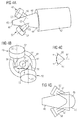
- FIGs. 4(a) and 4(b) show a perspective view and an end-view, respectively, of a burner according to the invention in an embodiment thereof.
- the burner comprises a frustoconical burner shell 40 attached to a combustion chamber 42. Attached to the shell 40 at diametrically opposite points on the circumference of the shell intermediate its larger-diameter end 44 and its smaller-diameter end 46 are two swirler arrangements 48, 50. These swirler arrangements are orientated so that their longitudinal axes 62 both form an angle ⁇ with the longitudinal axis 64 of the combustor (see Fig. 4(c) ) and are offset from that longitudinal axis 64 by a distance d (see Fig. 4(b) ).
- the swirler arrangements comprise an air swirler 52, 54 of the high-swirl-number type mounted to a pre-combustion chamber 56, 58. Air is introduced into the pre-combustion chambers through the swirlers, this air being mixed with fuel, which is fed into the swirler arrangements, the resulting swirling fuel-air mixture being ignited to produce the required combustion products for driving a downstream turbine.
- the swirler arrangements 48, 50 may be configured as disclosed in US 6,532,726 mentioned earlier. Thus, as illustrated in Figs.
- a head portion 120 is attached to the upstream end of a radial swirler 52/54 (in practice, an axial swirler might be used instead), which in turn is attached at its downstream end to a pre-combustion chamber 56/58 (see also Fig. 4 ).
- the swirler has a series of vanes 122, which define passages 124, into which air is introduced.
- the head portion 120 contains a series of pilot-fuel passages 126 and a series of main-fuel passages 128 for the introduction of liquid fuel into the head portion 120.
- gaseous pilot fuel will be introduced into a passage 130, from which it reaches an annular gallery 132, from which in turn it is deflected by a circumferential lip 134 across a central portion 136 of the head portion.
- Main gaseous fuel is introduced through passages 138.
- An igniter 140 is provided to ignite the fuel-air mix passing from the swirler 52/54 to the pre-combustion chamber 56/58.
- the swirler arrangements 48, 50 are orientated such as to produce a flame profile as illustrated in Fig. 4(d) (which is a simplified representation of the burner), in which it can be seen that the flame 45 starts off as two limbs 47 located in the pre-combustion chambers 56, 58. These limbs widen out and coalesce further downstream at the wider end of the frustoconical shell 40, finally emerging as a common flame front 49 located in the upstream end of the combustion chamber (not shown in Fig. 4(d) ).
- This flame profile can be achieved by arranging for the angle ⁇ to be such that the points of intersection 63 (see Fig.
- the location of the flame stabilization point can be moved by the use of pilot flames, which will act as flame holders feeding energy into the aerodynamic flow field where the pressure drop is too high for the main flame to re-ignite the incoming fuel-air mixture, but would simply extinguish otherwise.
- the flame can be allowed to stabilize in different locations even inside the shell.
- a burner made of a material with a lower melting point than the flame temperature e.g., most metals
- the material is, for example, a ceramic material or a superalloy, this can be allowed as long as flashback does not occur. Flashback is when the flame is spreading or progressing in low-velocity layers of the flow field, typically starting in the boundary layers on surfaces near the flame.
- Additional air is introduced into an opening 60 at the narrow end of the shell. Pilot fuel may be included along with the air. This additional air (and fuel) is fed between the rotating flow fields issuing from the swirler arrangements 48, 50. The combination of the two hot fuel-air flows from the swirler arrangements 48, 50 and the cooler air flow through the opening 60 of the shell results in rapid mixing. This is explained by considering that the higher-density cooler air from the shell inlet 60 will tend to centrifuge outward through and between the surrounding hot swirling flow fields, which causes very rapid mixing of the hot and cold streams.
- the effect of the invention as just described is a reduction in traverse due to the enhanced mixing that takes place.
- a further benefit is a reduction in harmful emissions relative to low-swirl burners achieving an equivalent traverse. Since the longitudinal axes of the swirler arrangements 48, 50 are not aligned with the combustor axis, axial acoustic-wave modes from the combustion chamber cannot couple simultaneously to all fuel and air inlet points in the swirlers. This effect tends to greatly reduce the tendency toward thermo-acoustic pulsations, which is a known limitation on all types of lean-premix systems.
- Fig. 6(a) is a much simplified schematic representation of the combustor, in which the swirler arrangements 48, 50 are not shown inclined with respect to the longitudinal axis of the burner and the shell 40 is merely suggested.
- the combusted pilot-fuel and air mixture creates an initial hot region (H) in the central region of the combustion area, to produce a robust flame stabilisation source, while the main-fuel and air mixture in the individual swirler arrangements 48, 50 produces a warm region (W) in the peripheral regions either side of the hot region.
- the arrows 70 represent the swirl of the combustion products as they move in a downstream direction.
- the arrows 70 lie in a plane orthogonal to the page.
- the hot flow mixes with the adjacent warm flows to provide a central region with a reduced temperature (shown here as warm (W), but in reality veering slightly towards hot), and peripheral regions which are more uniformly warm than the peripheral regions further upstream.
- the downstream swirl behaviour is shown by arrows 72 and 74, which are to be understood similarly to arrows 70. It should be noted that interactions between the flows from the swirler arrangements 48, 50 and the shell 40 and combustion chamber 42 will mean that rotation about the axis of the burner and merging of the original swirling flows from the two swirler arrangements will occur. This is represented by the use of different arrows 72,74.
- Fig. 6(b) contrasts the upstream and downstream regions in terms of traverse.
- the traverse at the upstream end is large with a monotonic profile, while the traverse at the downstream end is much reduced and with a somewhat undulating profile.
- the improved traverse at the downstream end is clearly evident.
- a second scenario illustrated in Fig. 7 , main fuel only and air are again introduced into the swirler arrangements 48, 50, while air only is introduced into the narrow end of the shell through opening 60.
- This gives rise initially to a (relatively) cold region (C) in the radial centre of the shell and combustion chamber, the peripheral regions being, as in the Fig. 6 case, warm (W).
- the profile becomes more as shown, with the central region being somewhere between cold and warm (i.e. tepid (T)) and being radially wider than at the upstream end.
- T cold and warm
- the result is a narrower traverse, and one which undulates rather than being monotonic.
- This pattern can be used at high load or full load, where the main burners are hot enough to be robustly stable on their own and the additional small emissions penalty of the pilot supply can be advantageously avoided.
- Fig. 8 shows the third scenario.
- both main fuel and pilot fuel are fed to the swirler arrangements 48, 50, while air only is fed into opening 60.
- C cold region
- W warm
- H hot
- a fourth scenario is illustrated in Fig. 9 .
- This scenario helps to achieve better low-emissions "turn-down" performance.
- Turn-down may be defined as the load range over which both the flame and the emissions level in the burner are stable. This range is limited due to the fact that, at reduced load, the air flow into the burner normally reduces more slowly than the fuel flow into the burner, so that the temperature of the flame drops, eventually extinguishing or pulsating.
- the low-emissions qualification here signifies the range of load over which a stable flame is achieved, whilst simultaneously keeping the emissions down.
- Enhanced low-emissions turn-down is obtained here by introducing different ratios of main fuel to air into the two swirler arrangements and by introducing air only into the shell through the opening 60.
- swirler arrangement 48 may have a high swirl number, while swirler arrangement 50 has a low swirl number, so that the two burners have similar emissions at their respective air-fuel ratios at full load.
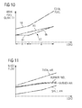
- the fuel-input regime is depicted in Fig. 10 , which is a graph of fuel quantity versus load.
- Curve 80 represents the increase in main fuel to burner 48 as the engine load increases, and can be seen to be linear.
- curve 82 which represents the main fuel into burner 50, is piecewise linear, with a section 84 being a constant fuel feed over an initial load range A and a section 86 being a linearly increasing fuel feed over a subsequent load range B up to full load.
- the total fuel feed into the two burners is shown as curve 88.
- swirler arrangement 48 has a higher swirl number than swirler arrangement 50, the fuel and air proceeding through it is better mixed than the fuel-air mixture proceeding through swirler arrangement 50. Consequently, even though swirler arrangement 48 has proportionately less air and runs hotter than swirler arrangement 50, the two produce similar emissions at full load. In addition the differences in the flow fields from the two swirler arrangements in this scenario further help to reduce the tendency to generate pulsations, which can be damaging to the turbine components. Interaction between the warm, cold and tepid flows shown upstream in Fig. 9 results in a somewhat smoothed-out distribution of both warm (W) and tepid (T) areas at the downstream end.
- main and pilot fuel will be gas rather than liquid.
- suitable aerothermal design part or all of the main fuel in liquid form could alternatively be introduced close to the pilot fuel through opening 60, rather than through the swirler arrangements 48, 50.
- One specific arrangement would be to design the main liquid fuel "injector" to spray the bulk of its fuel at and into the airstreams emerging from the two prechambers. This could be done using a fan-spray nozzle or two appropriately directed swirl or other type of atomisers. Since the air stream through opening 60 will have low or zero swirl, the droplets will have some time to spread and begin evaporating prior to meeting the strongly swirling flows of swirler arrangements 48, 50.
- a further variant of the invention involves running the two swirler arrangements 48, 50 at an air-fuel ratio somewhere near that at full load, while varying the air, and possibly also the pilot fuel, entering the opening 60 of the shell 40.
- a valve is included in the air inlet to the shell, in addition to the valve already required for the injection of fuel at this location.
- Fig. 11 is a graph of mass flow of fuel and air into the burner against engine load. If the pilot is operating in premixed mode, this would provide an alternative method of achieving low-emissions turndown at high load with the same general configuration.
- suitable aerodynamic design may permit the pilot to operate as a premixed stream when small amounts of gas fuel are pumped through it at high load, while at other load conditions it acts as a more stable diffusion-type flame with proportionately more fuel entering the pilot injection point.
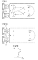
- a practical can-type combustor system normally employs more than one such burner spaced apart around the circumference of the engine radially outside the compressor.
- a perspective view of a six-combustor system is shown in Fig. 12 .
- the orientation of the swirler arrangements 48, 50 can be varied to suit the configuration of the engine as a whole.
- the swirler arrangements (which are shown in simplified form as a "T" shape) may be orientated to lie approximately radially relative to the longitudinal axis of the engine, or approximately tangentially to the circle on which the burners are located, or at any angle in between. It may be preferred to err more on the side of the Fig.
- Fig. 12 shows a swirler 109 attached to the opening at the narrow end of the frustoconical shell of each of the burners.
- this may be an axial or a radial swirler and helps to strengthen the interaction between the cold air entering the shell and the combustion products from the burners 48, 50.
- This extra swirler may be used in the earlier-described arrangements also.
- Figs. 13(a) and 13(b) the possibility, illustrated in Figs. 13(a) and 13(b) , of varying the orientation of the swirler arrangements 48, 50 can be used to advantage in ensuring that a particular temperature profile (e.g. as shown in Fig. 9(b) in connection with Fig. 9(a) ) obtains at the turbine end of the combustion chamber or its associated transition duct.
- this would mean arranging for the swirler arrangement 48, into which normal main fuel is introduced, to be located radially remote from the longitudinal axis of the turbine.
- Fig. 13(a) shows swirler arrangement 48 and the longitudinal axis 112 in that scenario.
- the can-type burner described above may also be employed as part of an annular combustor arrangement.
- a typical annular combustor arrangement is described in United States Patent No. 4,991,398 , issued to assignee United Technologies Corporation.
- Figs. 14(a) and 14(b) show a basic principle of a technique described in this patent.
- An annular combustor 90 has disposed at a dome end 92 thereof a number of fuel nozzles 94.
- the nozzles 94 are circumferentially spaced apart in two rows - a first, radially inner row 96 and a second, radially outer row 98, referred to a longitudinal axis 100 of the combustor.
- Each of the nozzles has its own swirler device and the directions of the swirl in each case are shown by the arrows 104.
- Reference numerals 106 and 108 represent the fuel-spray cones as they leave the nozzles.
- adjacent pairs of nozzles 94 are replaced by a burner as hereinbefore described - see Fig. 15 , which shows a single row of burners 110 in accordance with the invention.
- This has the advantage that adjacent swirler arrangements 48, 50 in each burner (see Figs. 4(a) and 4(b) ) act as "preferred partners" to each other, in a manner which is impossible with the nozzles 94 in Fig. 14(a) , since any one nozzle in Fig. 13(a) has two possible partners with which to interact. Having a preferred partner strengthens the interaction between the burners and also the predictability of the turbine entry pattern.
- each pair of swirler arrangements 48, 50 is isolated from the cross-flow, which is generated around an annular combustor such as is illustrated in Figs. 14(a) and 14(b) .
- This cross-flow tends to weaken the burner stability and the resistance to thermo-acoustic pulsation.
- a further advantage is that, due to the use of the frustoconical shell 40 (see Figs. 4(a) and 4(b) ), it is possible to place the burners in various orientations relative to the longitudinal axis of the shell, whereas in the conventional annular arrangement the placing of the nozzles is more restricted by the need to fire more or less directly down the annulus
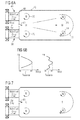
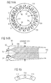
- FIG. 16 A configuration including three swirler arrangements, which forms a second embodiment of the invention, is shown in Fig. 16 .
- Whether or not it is advantageous to employ more than two depends on the application. Where the burner is small, there will be little advantage. Indeed, the use of three or more swirler arrangements could easily be a disadvantage, since then they would be smaller with consequently greater constraints on mechanical tolerances, hence greater difficulties in manufacture.
- a larger burner might easily employ more than two, the advantage then being greater control over the fuel-air characteristics in relation to load, etc. This would represent an extension of the principle shown in Figs.
- the burner of the present invention may be put to advantageous use in a silo combustor.
- An example of a silo combustor is described in EP 0571782 , filed in the name of Asea Brown Boveri, AG.
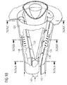
- the combustor (see Fig. 17 ) comprises a large number of premix burners 120 distributed around the dome-end of the combustion chamber 122.
- the burners 120 are each configured as shown in Fig. 18 .
- Figs. 19(a), (b) and (c) show sections through the burner along lines XIXA, XIXB and XIXC, respectively.
- the burners consist of two half-conical portions 124, 126 having axes 128, 130, which are offset from each other.
- This offset has the effect of creating two diametrically opposite spaces 132 and 134 for the ingress of compressed air, as shown by the arrows 136.
- the air flows into a combustion space 138 between the two half-conical portions 124, 126, where it mixes with fuel introduced by a fuel injector 140.
- the compressed air is guided into the combustion space by two guide plates 142, 144, which are not shown in full in Fig. 18 for the sake of clarity.
- control of fuel-air mixing in the burner can be achieved by varying one or more of: the swirl number of the swirlers in the individual burners, the offset distance d , the angle of inclination ⁇ and the axial placement of the swirler arrangements.
- One possible orientation of the swirler arrangements relative to the shell has already been described, namely setting the angle ⁇ so that, for the axial location at which the swirler arrangements connect to the shell, the axes 62 (see Fig. 4(c) ) of the swirler arrangements intersect with respective lines parallel with the longitudinal axis 64 of the burner somewhere in the region of the wider end 44 of the shell.
- Offset distance d will be determined by the required degree of interaction between the pilot air (and/or fuel) flow at the radial centre of the shell and the fuel-air flows from the swirler arrangements, which in turn is determined by the temperature profile which might be required at the downstream end of the combustion chamber, or even further downstream near the turbine blades.
- the invention also envisages a situation, in which they have a low swirl number. Such a situation, however, is not preferred, since a low swirl number means less efficient mixing generally, and higher emissions. Furthermore, it is normally only with high-swirl burners that the traverse problem is very significant.
Landscapes
- Engineering & Computer Science (AREA)
- Chemical & Material Sciences (AREA)
- Combustion & Propulsion (AREA)
- Mechanical Engineering (AREA)
- General Engineering & Computer Science (AREA)
Applications Claiming Priority (1)
| Application Number | Priority Date | Filing Date | Title |
|---|---|---|---|
| GB0723450A GB2455289B (en) | 2007-12-03 | 2007-12-03 | Improvements in or relating to burners for a gas-turbine engine |
Publications (1)
| Publication Number | Publication Date |
|---|---|
| EP2068076A2 true EP2068076A2 (de) | 2009-06-10 |
Family
ID=38962384
Family Applications (1)
| Application Number | Title | Priority Date | Filing Date |
|---|---|---|---|
| EP08168391A Withdrawn EP2068076A2 (de) | 2007-12-03 | 2008-11-05 | Verbesserungen in oder in Bezug auf Brenner für ein Gasturbinentriebwerk |
Country Status (3)
| Country | Link |
|---|---|
| US (1) | US20090139242A1 (de) |
| EP (1) | EP2068076A2 (de) |
| GB (1) | GB2455289B (de) |
Cited By (1)
| Publication number | Priority date | Publication date | Assignee | Title |
|---|---|---|---|---|
| RU2498160C2 (ru) * | 2009-04-29 | 2013-11-10 | Сименс Акциенгезелльшафт | Горелка для газотурбинного двигателя |
Families Citing this family (5)
| Publication number | Priority date | Publication date | Assignee | Title |
|---|---|---|---|---|
| EP2299178B1 (de) | 2009-09-17 | 2015-11-04 | Alstom Technology Ltd | Verfahren und Gasturbinenverbrennungssystem zum sicheren Mischen von H2-reichen Brennstoffen mit Luft |
| EP2653780A1 (de) * | 2012-04-16 | 2013-10-23 | Siemens Aktiengesellschaft | Behandlung eines Abschnitts einer Strömungsmaschine |
| EP3062019B1 (de) * | 2015-02-27 | 2018-11-21 | Ansaldo Energia Switzerland AG | Verfahren und vorrichtung zur flammenstabilisation in einem brennersystem einer stationären brennkraftmaschine |
| EP3098514A1 (de) * | 2015-05-29 | 2016-11-30 | Siemens Aktiengesellschaft | Brennkammer |
| US11774093B2 (en) | 2020-04-08 | 2023-10-03 | General Electric Company | Burner cooling structures |
Citations (9)
| Publication number | Priority date | Publication date | Assignee | Title |
|---|---|---|---|---|
| US4141495A (en) | 1977-06-02 | 1979-02-27 | Werner Diermayer | Draft control arrangement for combustion apparatus |
| GB1601218A (en) | 1978-03-20 | 1981-10-28 | Rolls Royce | Combustion equipment for gas turbine engines |
| US4991398A (en) | 1989-01-12 | 1991-02-12 | United Technologies Corporation | Combustor fuel nozzle arrangement |
| EP0571782A1 (de) | 1992-05-27 | 1993-12-01 | Asea Brown Boveri Ag | Verfahren zum Betrieb einer Brennkammer einer Gasturbine |
| US5351474A (en) | 1991-12-18 | 1994-10-04 | General Electric Company | Combustor external air staging device |
| EP0704657A2 (de) | 1994-10-01 | 1996-04-03 | ABB Management AG | Brenner |
| US6532726B2 (en) | 1998-01-31 | 2003-03-18 | Alstom Gas Turbines, Ltd. | Gas-turbine engine combustion system |
| EP1510755A1 (de) | 2003-09-01 | 2005-03-02 | Alstom Technology Ltd | Brenner mit Brennerlanze und gestufter Brennstoffeindüsung |
| US6892543B2 (en) | 2002-05-14 | 2005-05-17 | Mitsubishi Heavy Industries, Ltd. | Gas turbine combustor and combustion control method thereof |
Family Cites Families (10)
| Publication number | Priority date | Publication date | Assignee | Title |
|---|---|---|---|---|
| GB577865A (en) * | 1943-01-21 | 1946-06-04 | Armstrong Siddeley Motors Ltd | Liquid-fuel combustion-chamber |
| US4154567A (en) * | 1977-01-07 | 1979-05-15 | Continental Carbon Company | Method and apparatus for the combustion of waste gases |
| EP0481111B1 (de) * | 1990-10-17 | 1995-06-28 | Asea Brown Boveri Ag | Brennkammer einer Gasturbine |
| CH684963A5 (de) * | 1991-11-13 | 1995-02-15 | Asea Brown Boveri | Ringbrennkammer. |
| GB2319078B (en) * | 1996-11-08 | 1999-11-03 | Europ Gas Turbines Ltd | Combustor arrangement |
| US6832481B2 (en) * | 2002-09-26 | 2004-12-21 | Siemens Westinghouse Power Corporation | Turbine engine fuel nozzle |
| EP1649219B1 (de) * | 2003-07-25 | 2008-05-07 | Ansaldo Energia S.P.A. | Gasturbinenbrenner |
| US7870736B2 (en) * | 2006-06-01 | 2011-01-18 | Virginia Tech Intellectual Properties, Inc. | Premixing injector for gas turbine engines |
| US8015814B2 (en) * | 2006-10-24 | 2011-09-13 | Caterpillar Inc. | Turbine engine having folded annular jet combustor |
| AU2008261981A1 (en) * | 2007-06-06 | 2008-12-18 | North Carolina State University | Process for combustion of high viscosity low heating value liquid fuels |
-
2007
- 2007-12-03 GB GB0723450A patent/GB2455289B/en not_active Expired - Fee Related
-
2008
- 2008-11-05 EP EP08168391A patent/EP2068076A2/de not_active Withdrawn
- 2008-12-02 US US12/315,318 patent/US20090139242A1/en not_active Abandoned
Patent Citations (9)
| Publication number | Priority date | Publication date | Assignee | Title |
|---|---|---|---|---|
| US4141495A (en) | 1977-06-02 | 1979-02-27 | Werner Diermayer | Draft control arrangement for combustion apparatus |
| GB1601218A (en) | 1978-03-20 | 1981-10-28 | Rolls Royce | Combustion equipment for gas turbine engines |
| US4991398A (en) | 1989-01-12 | 1991-02-12 | United Technologies Corporation | Combustor fuel nozzle arrangement |
| US5351474A (en) | 1991-12-18 | 1994-10-04 | General Electric Company | Combustor external air staging device |
| EP0571782A1 (de) | 1992-05-27 | 1993-12-01 | Asea Brown Boveri Ag | Verfahren zum Betrieb einer Brennkammer einer Gasturbine |
| EP0704657A2 (de) | 1994-10-01 | 1996-04-03 | ABB Management AG | Brenner |
| US6532726B2 (en) | 1998-01-31 | 2003-03-18 | Alstom Gas Turbines, Ltd. | Gas-turbine engine combustion system |
| US6892543B2 (en) | 2002-05-14 | 2005-05-17 | Mitsubishi Heavy Industries, Ltd. | Gas turbine combustor and combustion control method thereof |
| EP1510755A1 (de) | 2003-09-01 | 2005-03-02 | Alstom Technology Ltd | Brenner mit Brennerlanze und gestufter Brennstoffeindüsung |
Cited By (2)
| Publication number | Priority date | Publication date | Assignee | Title |
|---|---|---|---|---|
| RU2498160C2 (ru) * | 2009-04-29 | 2013-11-10 | Сименс Акциенгезелльшафт | Горелка для газотурбинного двигателя |
| US8739545B2 (en) | 2009-04-29 | 2014-06-03 | Siemens Aktiengesellschaft | Burner for a gas turbine engine |
Also Published As
| Publication number | Publication date |
|---|---|
| GB2455289A9 (en) | 2009-12-30 |
| GB2455289A (en) | 2009-06-10 |
| US20090139242A1 (en) | 2009-06-04 |
| GB0723450D0 (en) | 2008-01-09 |
| GB2455289B (en) | 2010-04-07 |
Similar Documents
| Publication | Publication Date | Title |
|---|---|---|
| EP1426689B1 (de) | Gasturbinenbrennkammer mit Vormischbrennern, die eine verschiedene Geometrie aufweisen | |
| EP1985927B1 (de) | Verbrennungssystem einer Gasturbine mit Mager-Direkt-Einspritzung zur Reduzierung von NOx-Emissionen | |
| EP0961907B1 (de) | Brennkammer | |
| EP1795809B1 (de) | Gasturbinenbrennkammer | |
| EP2407720B1 (de) | Flammentolerante Sekundärbrennstoffdüse | |
| US7886991B2 (en) | Premixed direct injection nozzle | |
| EP2253887B1 (de) | Brennkammer mit verbesserter Anordnung von Quenchlöchern | |
| US5899075A (en) | Turbine engine combustor with fuel-air mixer | |
| US8984889B2 (en) | Combustor for a gas-turbine engine with angled pilot fuel nozzle | |
| US20090056336A1 (en) | Gas turbine premixer with radially staged flow passages and method for mixing air and gas in a gas turbine | |
| US20050097889A1 (en) | Fuel injection arrangement | |
| EP2551598B1 (de) | Verfahren zum betreiben einer turbomaschine | |
| KR20190104900A (ko) | 가스 터빈 엔진용 연료 분사기 조립체 | |
| WO2014141397A1 (ja) | ガスタービン燃焼器 | |
| GB2593123A (en) | Combustor for a gas turbine | |
| EP2068076A2 (de) | Verbesserungen in oder in Bezug auf Brenner für ein Gasturbinentriebwerk | |
| JP2016057056A (ja) | ガスタービンの燃焼器用の希釈ガス又は空気混合器 | |
| EP3403028B1 (de) | Gasturbinenbrennkammer | |
| EP3485197B1 (de) | Verfahren zur direkten kraftstoffverteilung in brennkammern von gasturbinen und brennkammer von gasturbinen | |
| EP1243854B1 (de) | Brennstoffeinspritzventil | |
| JP2767403B2 (ja) | ガスタービン用低NOxバーナ | |
| Zuo et al. | Premixed direct injection nozzle |
Legal Events
| Date | Code | Title | Description |
|---|---|---|---|
| PUAI | Public reference made under article 153(3) epc to a published international application that has entered the european phase |
Free format text: ORIGINAL CODE: 0009012 |
|
| AK | Designated contracting states |
Kind code of ref document: A2 Designated state(s): AT BE BG CH CY CZ DE DK EE ES FI FR GB GR HR HU IE IS IT LI LT LU LV MC MT NL NO PL PT RO SE SI SK TR |
|
| AX | Request for extension of the european patent |
Extension state: AL BA MK RS |
|
| STAA | Information on the status of an ep patent application or granted ep patent |
Free format text: STATUS: THE APPLICATION IS DEEMED TO BE WITHDRAWN |
|
| 18D | Application deemed to be withdrawn |
Effective date: 20120601 |