EP2653780A1 - Behandlung eines Abschnitts einer Strömungsmaschine - Google Patents
Behandlung eines Abschnitts einer Strömungsmaschine Download PDFInfo
- Publication number
- EP2653780A1 EP2653780A1 EP12164296.1A EP12164296A EP2653780A1 EP 2653780 A1 EP2653780 A1 EP 2653780A1 EP 12164296 A EP12164296 A EP 12164296A EP 2653780 A1 EP2653780 A1 EP 2653780A1
- Authority
- EP
- European Patent Office
- Prior art keywords
- fuel
- component
- combustion chamber
- section
- flow engine
- Prior art date
- Legal status (The legal status is an assumption and is not a legal conclusion. Google has not performed a legal analysis and makes no representation as to the accuracy of the status listed.)
- Withdrawn
Links
Images


Classifications
-
- C—CHEMISTRY; METALLURGY
- C11—ANIMAL OR VEGETABLE OILS, FATS, FATTY SUBSTANCES OR WAXES; FATTY ACIDS THEREFROM; DETERGENTS; CANDLES
- C11D—DETERGENT COMPOSITIONS; USE OF SINGLE SUBSTANCES AS DETERGENTS; SOAP OR SOAP-MAKING; RESIN SOAPS; RECOVERY OF GLYCEROL
- C11D7/00—Compositions of detergents based essentially on non-surface-active compounds
- C11D7/22—Organic compounds
- C11D7/40—Products in which the composition is not well defined
-
- F—MECHANICAL ENGINEERING; LIGHTING; HEATING; WEAPONS; BLASTING
- F23—COMBUSTION APPARATUS; COMBUSTION PROCESSES
- F23D—BURNERS
- F23D11/00—Burners using a direct spraying action of liquid droplets or vaporised liquid into the combustion space
- F23D11/36—Details
- F23D11/38—Nozzles; Cleaning devices therefor
- F23D11/386—Nozzle cleaning
-
- B—PERFORMING OPERATIONS; TRANSPORTING
- B08—CLEANING
- B08B—CLEANING IN GENERAL; PREVENTION OF FOULING IN GENERAL
- B08B7/00—Cleaning by methods not provided for in a single other subclass or a single group in this subclass
-
- F—MECHANICAL ENGINEERING; LIGHTING; HEATING; WEAPONS; BLASTING
- F23—COMBUSTION APPARATUS; COMBUSTION PROCESSES
- F23D—BURNERS
- F23D2900/00—Special features of, or arrangements for burners using fluid fuels or solid fuels suspended in a carrier gas
- F23D2900/00002—Cleaning burner parts, e.g. burner tips
-
- F—MECHANICAL ENGINEERING; LIGHTING; HEATING; WEAPONS; BLASTING
- F23—COMBUSTION APPARATUS; COMBUSTION PROCESSES
- F23D—BURNERS
- F23D2900/00—Special features of, or arrangements for burners using fluid fuels or solid fuels suspended in a carrier gas
- F23D2900/31018—Nozzles and cleaning devices therefor
-
- F—MECHANICAL ENGINEERING; LIGHTING; HEATING; WEAPONS; BLASTING
- F23—COMBUSTION APPARATUS; COMBUSTION PROCESSES
- F23R—GENERATING COMBUSTION PRODUCTS OF HIGH PRESSURE OR HIGH VELOCITY, e.g. GAS-TURBINE COMBUSTION CHAMBERS
- F23R2900/00—Special features of, or arrangements for continuous combustion chambers; Combustion processes therefor
- F23R2900/00004—Preventing formation of deposits on surfaces of gas turbine components, e.g. coke deposits
Definitions
- the present invention relates to a method for a treatment of at least a section of a flow engine.
- combustion chambers of gas turbines fuel is burned for generating thermal energy.
- the combustion chamber comprises a burner body with a pilot burner face, wherein the latter comprises a liquid fuel lance having a conduit for guiding the liquid fuel to a tip provided for injecting pilot fuel into the combustion chamber. Holes are provided in the tip for injecting cooling medium, which cools the lance tip and interacts with the fuel injected from the lance tip to create a homogeneous air/fuel mixture.
- the critical surfaces of the elements of a gas turbine that are in contact with fuel are coated with high temperature alloys with a coke inhibiting layer.
- a method for a treatment of at least a section of a flow engine is presented.
- the at least one section of the flow engine is treated with at least a component with at least a biocatalytic activity. Due to the inventive matter an environmental friendly method can be provided. Moreover, it operates independently, especially from an external source, e.g. an operator or an energy source. It should be noted, that a supplying of a specific environment, like an adjusted or applied temperature, pressure, humidity, pH-value, salt-concentration, radiation (IR-, UV-, VIS-, X- or radioactive radiation) or similar should not be understood as external source. Further, the inventive method performs without a damage of the at least one component or the base material of the at least one component.
- a flow engine is intended to mean any engine or machine suitable for a person skilled in the art, e.g. a thermal heating plant, a gas turbine or an internal combustion engine.
- the phrase "for a treatment” should be understood as any possible treatment which is employable for a person skilled in the art, like a coating, finishing, deburring, dyeing, stripping, polishing, cleaning etc.
- a “biocatalytic activity” is intended to mean the ability to transform, convert, process, digest, catabolise, metabolise or any other action suitable for a person skilled in the art, at least one material or substance by means of a biological mechanism or process.
- a biological process is intended to mean a process which contributes to a function of a living unit, like a cell, a tissue, an organ or an organism.
- the effected material or substance could be any material suitable for a person in the art, like a gas, a fluid or a solid material e.g. a metal, an alloy, a ceramic, a glass, a polymer, a rubber, grease, an oil, an organic compound or composition etc.
- a “component with at least a biocatalytic activity” may be a substance, a mixture of at least two substances, at least one organism and/or a combination of at least a substance and at least one organism, which possesses the at least one biocatalytic activity.
- the component is chosen from the group comprising of DNA, RNA, mRNA, siRNA, a peptide, a protein or an active fragment thereof, an enzyme or an active fragment thereof, an antibody or an active fragment thereof, a cell, a cell culture, a tissue, an organ, an organism, a prokaryote, an eukaryote, a protozoa, a metazoan, a microbe, a virus, a bacterium, an archaea, a fungus, an alga, an animal, a plant or the like.
- the component may have more than one biocatalytic activity. Hence, at least two functions or even treatments could be facilitated with one component.
- the at least one component with at least one biocatalytic activity is provided from at least a living organism.
- the living mechanism is able to operate the method self-acting and automatic.
- the term "provide” should be understood as "build, make, compose, generate and/or secrete”.
- the living organism may provide the at least one component with at least one biocatalytic activity in situ or beforehand of the treatment and in the latter case may be obtained, harvested or recovered in laboratory scale. Further, the living organism may be any living organism known to a person skilled in the art and can be e.g.
- a prokaryote an eukaryote, a protozoa, a metazoan, a microbe, a virus, a bacterium, an archaea, a fungus, an alga, an animal or a plant.
- a virus is an infectious particle that can't live autarkic they are deliberately included in the scope of the invention for example due to their effects in combination with e.g. living organisms.
- the at least one component with the at least one biocatalytic activity is provided from at least a microbe. Due to the easy breeding and harvesting of microbes the at least one component with the at least one biocatalytic activity can be obtained in large quantity in a big scale approach.
- the microbe may be any microbe known to a person skilled in the art and can be e.g. a virus, a bacterium, an archaea, a fungus, an alga, a protist, and microscopic plant, like green algae, or an animal, like plankton or planarian.
- the at least one component with the at least one biocatalytic activity is at least a living organism, like a microbe, a virus, a bacterium, an archaea, a fungus, an alga, an animal or a plant.
- a living organism like a microbe, a virus, a bacterium, an archaea, a fungus, an alga, an animal or a plant.
- the microbe may be a microbe that is known to ingest chemical energy from minerals or ancient carbon found for example in carbon-rich sources, like shale, rocks or volcanic rocks, respectively. These sources are e.g. sediments at the present the sea floor or at former ocean floors transformed now to formation above or slightly beneath (approx. 100 cm) the ground.
- the microbe is a bacterium or an archaea.
- Growth, harvest, incubation, treatment conditions and/or the like beforehand and/or during the treatment of the at least one section of the flow engine, such as temperature, pressure, humidity, pH-value, salt-concentration or radiation, of all the aforementioned substances and/or organisms may be adjusted due to the used substance, organism and/or treatment. This will be accomplished by a person skilled in the art due to his knowledge independently.
- At least one active part/component of the at least one component with the at least one biocatalytic activity is use for the treatment of the at least one section of the flow engine.
- This may advantageously be a protein, a peptide, an enzyme and/or antibody or an active fragment thereof.
- the at least one active part/component complex affords for live maintenance of the living organism may be omitted.
- storage and handling of the at least one component with the at least one biocatalytic activity may be simplified.
- the at least one component with the at least one biocatalytic activity is used for degradation of at least a substance with high hydrocarbon content. Due to this, an easy and effective method for disposing of a contaminating, surplus and/or undesired processing material, post-production material, cleaning material or starting material, such as lubricant residues, coating residues, cleaning gas or solvent, fuel, cooling medium and/or deposited reaction products can be provided.
- degradation is intended to mean a chemical decomposition or breakdown, where a separation of a chemical compound into elements or simpler compounds occurs.
- the at least one substance with high hydrocarbon content is built from at least a kerogen.
- a kerogen is intended to mean any type of mixture of organic material (type I to type IV kerogen) of sapropelic, planktonic or humic origin.
- the at least one component with at least one biocatalytic activity is used for cleaning of the at least one section of the flow engine.
- the at least one section of the flow engine comprises at least a part of a combustion chamber of a gas turbine. Due to this inventive matter a section which is highly affected by the treatment and/or habitually causes problems due to its high contamination during the combustion process can be treated efficiently and properly. This problem is particularly accentuated for gas turbines using dry low emissions (DLE). Furthermore coking can also be experienced in other than DLE combustion systems operating with poor quality liquid fuels, e.g. specific types of diesel or heating oils. Problems potentially could also be experienced with gas fuels, i.e. coke oven gas or with heavy hydrocarbons. Thus, a reliability of a combustion chamber of such flow engines may be improved.
- DLE dry low emissions
- the part of the combustion chamber of the gas turbine is a wall or face e.g. a side wall of a pre-chamber volume.
- a surface exposed to a volume or operation environment of the combustion chamber may be advantageously treaded or cleaned, respectively, with the inventive method.
- the part of the combustion chamber of the gas turbine is advantageously a fuel injection device, thus the inventive method provides a treatment of a part of the combustion chamber which is highly affected and/or operationally subjected to high contamination during operation of the flow engine.
- the fuel injection device is embodied as a fuel injection aperture.
- the part of the combustion chamber of the gas turbine is an igniter device and/or at least advantageously comprises an igniter in a burner body.
- a treatment of the part of the combustion chamber including an igniter tip of the igniter device is homogenous, because the inventive method provides equally access to all surfaces, even in angled configurations.
- the igniter device is embodied as an igniter.
- the igniter device may use a fuel in a torch like embodiment e.g. a spark or plasma or laser to ignite the fuel air mixture. During operation the igniter may also over time experience build up of deposits requiring a treatment to regain its performance to reliably ignite the flame in the combustion chamber during the start sequence of the gas turbine.
- the part of the combustion chamber of the gas turbine may be a pilot burner face of a burner body. Hence, clean result without damage of a base material of the burner body can be obtained.
- the part of the combustion chamber of the gas turbine is advantageously a fluid nozzle and/or at least comprises a fluid nozzle in a burner body. Due to the inventive method, a treatment of the fluid nozzle and/or of the part of the combustion chamber including the fluid nozzle is homogenous, because the inventive method provides equally access to all surfaces, even in angled configurations.
- the term "fluid nozzle" should be understood as any injection device or aperture of the combustion chamber for any fluid feasible for a person skilled in the art, like a fuel and/or a cooling medium.
- a use of at least a component with at least a biocatalytic activity for a treatment of at least a section of a flow engine is presented. Due to the inventive matter a use of an environmental friendly component can be applied. Furthermore, the use is independent, especially from an external source, e.g. an operator or an energy source. Further, the at least one component with at least one biocatalytic activity performs without a damage of the at least one component or the base material of the at least one component.
- the at least one component with the at least one biocatalytic activity may be applied to the at least one section of the flow engine with any method feasible for a person skilled in the art, e.g. exposing, coating, spraying or incubating/submerging in particular with/in a solution.
- the at least one section of the flow engine is incubated in at least a solution containing at least the at least one component with the at least one biocatalytic activity.
- This action does favourably not require supervision.
- the active component may have equally access to all surfaces, even in angled configurations, ensuring a homogenous treatment result.
- the treatment of the at least one section may include full submersion of the at least one section or partial submersion i.e. only exposing the surfaces showing the carbonization to the solution.
- the at least one section of the flow engine may be exposed in another way than (partly) submersion in the solution, like applying or spraying the at least one solution containing at least the at least one component with the at least one biocatalytic activity i.e. as a coating on the at least one section or on the carbonization.
- the invention relevant main features of the flow engine or the gas turbine are briefly summarised.
- the combustion chamber comprises at least a main combustion volume and a swirler device.
- a swirler of the swirler device is located upstream of the combustion volume.
- a pre-chamber guides the flow between the swirler and the main combustion volume.
- the combustion chamber comprises at least an injection device or aperture, respectively, such that fuel is injectable into the combustion chamber.
- a fuel injection aperture or hole is arranged in a pilot burner face of a burner body and injects the pilot fuel stream into the combustion chamber.
- the injection aperture may be arranged at a pilot tip of a fuel lance and may be provided with the fuel via a fuel conduit.
- the pilot tip may has a width (diameter) of more than approximately 3 mm, preferably more than approximately 5 mm and less than approximately 25 mm (Millimetres).
- the combustion chamber comprises at least an igniter device such that the fuel air mixture is ignitable during start up.
- the ignition device may be an igniter or a conduit providing hot combustion gases from a neighbouring combustion chamber via a so-called cross ignition or cross lightning tube.
- the fuel may be any fuel feasible for a person in the art, e.g. a gaseous fuel and/or a liquid fuel, like heating oil and/or diesel fuel, etc.
- the combustion chamber or the pilot burner face, respectively, may additionally comprise an inlet channel with at least an inlet hole or preferably a plurality of inlet holes for injecting a cooling medium into the combustion chamber.
- the inlet channel may have a width (diameter) of more than approximately 0.2 mm, preferably more than approximately 1 mm and less than approximately 10 mm (Millimetres).
- the combustion chamber or the pilot burner face, respectively, may in addition for example have at least an inlet hole or preferably a plurality of inlet holes for injecting an additional fuel e.g. different fuel into the combustion chamber.
- the inlet holes may have a width (diameter) of more than approximately 0.2 mm, preferably more than approximately 0.5 mm and less than approximately 5 mm (Millimetres).
- the inlet channel may be formed with a circular, elliptical, triangular, rectangular shape or a combination thereof, for example.
- the width may be defined by the hydraulic diameter i.e. the diameter of the circular shape, or the semiminor axis of an elliptical shape or the distance of opposed sides of a rectangular shape.
- the combination of the number of and dimension of the individual apertures can be selected to promote and control the fuel air mixing and the fuel distribution in the combustion chamber.
- the achievable time of operation between maintenance may depend on the location and dimension of the fluid aperture. Hence, by using such a larger inlet channel, the risk of completely blocking the inlet channel by coke or carbonized layers may be reduced.
- the cooling medium in the combustion chamber may be, for example, air, steam, a gas fuel e.g. natural gas, a fluid, such as water, or other cooling fluids, which are suitable for cooling e.g. the pilot burner face.
- a cooling medium is applied that cools the pilot burner face and particularly any fuel injection devices and is additionally usable for supporting the combustion inside the combustion chamber, such as an oxidant, e.g. air.
- the inlet channel and the inlet holes, respectively, for injecting the cooling medium is/are placed close to the fuel injection aperture for generating a sufficient cooling energy for cooling the fuel injection aperture and the fuel lance.
- a plurality of injection channels for injecting the cooling medium is formed preferably around a circumferential direction along the fuel injection aperture.
- the pilot burner face or a surface exposed to carbonized fuel is preferably alloyed with titanium or a titanium compound.
- titanium is lesser reactive than other metal materials, such as steel or nickel, a clogging and an adhesion of carbonized fuel may be reduced.
- the carbonization may have different causes. As described above, during start-up and low load operation fuel may carbonize onto surfaces of the combustion chamber. Moreover, most gas turbines are designed for so called dual fuel operation, wherein the main fuel is typically natural gas and a back up fuel, used when the main fuel is not available or low in supply, is typically a heating oil or kerosene. During operation it is possible to switch between the fuels without stopping the gas turbine. It may even be possible to continuously run on both fuels at the same time. In such a situation it may be an option to use natural gas instead of air to keep the lance tip cool. The gas fuel is cooler than the air from the compressor and would have a marginal impact on emissions particularly if traded off against the gas pilot fuel flow.
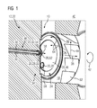
- FIG 1 shows a perspective view of a section 10 of a combustion chamber 18 of a not in detail shown flow engine 12 embodied as a gas turbine 22.
- the combustion chamber 18 is formed with a tubular-like shape (not shown in detail) which extends in axial direction 38 and comprises a pre-chamber volume 26 and a main chamber 40, wherein the latter extends in a circumferential direction 42 around the pre-chamber volume 26.
- the combustion chamber 18 comprises a side wall 24, which extends basically in a direction 44 perpendicular to the axial direction 38 and is located axially adjacent to the pre-chamber volume 26.
- the side wall 24 is a part of a burner body 34 of the combustion chamber 18.
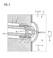
- the burner body 34 comprises as a part 20 of the combustion chamber 18 and the side wall 24 a pilot burner face 46, which is a section of a liquid fuel lance 48 that is inserted in the burner body 34.
- the liquid fuel lance 48 has a fuel conduit 50 for guiding a liquid or pilot fuel, like No. 2 heating oil, also known as diesel fuel, to a pilot or liquid fuel tip 52 for injection of the liquid fuel. Therefore, the pilot burner face 46, forming a part of the side wall 24, and hence the combustion chamber 18 comprises as a further part 20 of the combustion chamber 18 a fluid nozzle 32, which is embodied as the fuel injection device 28 or a fuel injection aperture.
- the pilot burner face 46 or the liquid fuel tip 52 comprises as further fluid nozzles 28 several inlet holes 54 for injecting a cooling medium, e.g. air, from a cooling channel 56 extending basically in parallel to and in circumferential direction 42 around the fuel conduit 50 into the combustion chamber 18.
- the inlet holes 54 are formed circumferentially around the fuel injection device 28 or aperture as to promote the characteristics of the spray.
- the cooling medium is normally supplied from a compressor discharge of the gas turbine 22 utilizing the same available pressure drop as the main flow through the burner, however flowing in a parallel stream for the two flows to be joined in the burner cavity.
- an igniter device comprising an igniter 30 is attached to the burner body 34 in order to ignite the injected fuel during start-up.
- the inlet holes 54 have a cross-section through which cooling medium is injected which interacts with the pilot fuel injected in the direction 58 through the fuel injection device 28 or aperture of the pilot burner face 46.
- the pilot burner face 46 may locally reach temperatures between approximately 800°C - 1000 C (Celsius) during operation.
- the inlet holes 54 for injecting cooling air cool the lance tip 52 and the injected cooling medium interacts with the fuel injected from the lance tip 52 to create a homogeneous air/fuel mixture.
- An outer volume 60 of the combustion chamber 18, which extends in circumferential direction 42, comprises a swirler device, embodied as a swirler 62, wherein the swirler 62 is adapted for injecting a main fuel/air stream in circumferential direction 42 into the main chamber 40.
- the injected pilot liquid fuel and the injected cooling medium are injected for controlling the combustion of the main fuel/air mixture stream which flows through the swirler 62 of the combustion chamber 18.
- the main acting force on the liquid fuel droplets inside the combustion chamber 18 is the flow field created by the swirler 62 in the combustion chamber 18.
- the flow field created by the swirler 62 forms a helical run of the fuel droplets along the axial direction 38 in the combustion chamber 18.
- the main fuel i.e. fuel air mixture stream 64 of the flow field containing the fuel droplets is indicated by the arrows printed in FIG 1 .
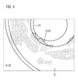
- the entered fuel may be deposited as a substance 16 with a high hydrocarbon content or out of a kerogen, respectively, and/or may carbonize as a carbonization 66 on parts 20 of the combustion chamber 18 e.g.
- the deposited substance 16 will reduce the start reliability of the gas turbine 22 as well as the emission performance.
- areas 70 where the surface temperature reaches sufficiently high levels during operation the fuel residuals will burn off, e.g. in the centre portion of the pilot burner face 46. This situation is schematically shown in FIG 3 and 4 .
- This substance 16 and/or carbonisation 66 can be removed by degradation with an inventive method for a treatment or a cleaning, respectively, of the section 10 of the flow engine 12 or the side wall 24 or the part 20 (pilot burner face 46 or a fuel nozzle 28 or the igniter 30) of the combustion chamber 18 (in the following text the terms section 10 of the flow engine 12 is used synonymously for the term part 20 of the combustion chamber 18).
- the section 10 of the flow engine 12 is treated with a component 14 with a biocatalytic activity.
- the component 14 with the biocatalytic activity which metabolises or removes by degradation the high hydrocarbon content and/or the kerogens of the substance 16 and/or carbonization 66, is a microbe and thus a living organism.
- the component 14 is provided from a microbe or a living organism, respectively, and may be, for example, an enzyme of the microbe metabolising or removing by degradation the high hydrocarbon content and/or the kerogens of the substance 16.
- the component 14 with the biocatalytic activity is used for the treatment of the section 10 of a flow engine 12 and specifically by incubating the section 10 in a solution 36, which contains the component 14 with the biocatalytic activity.
- a solution 36 which contains the component 14 with the biocatalytic activity.
- FIG 5 shows schematically the pilot burner face 46 with the fluid nozzles 28 and the igniter 30 contaminated with the substance 16 and disassembled from the flow engine 12 during the treatment with the component 14 with a biocatalytic activity according to the inventive method.
- the incubation time t will be adjusted in a way so that the carbonization 66 will be completely removed.
- the treatment of the section 10 may include full submersion of the section 10 or partial submersion i.e. only exposing the surfaces showing the carbonization 66 to the solution 36.
- a dissembled burner face gets the treatment by the component 14.
- component 14 may be injected into an assembled gas turbine combustion chamber such that it able to affect the carbonized surfaces in a still assembled burner within the combustion chamber.
- a cap is placed over the burner face such that the component 14 will be encapsuled by the burner face and surfaces of the cap. The component 14 then can affect the burner face.
Landscapes
- Engineering & Computer Science (AREA)
- Chemical & Material Sciences (AREA)
- Combustion & Propulsion (AREA)
- Mechanical Engineering (AREA)
- General Engineering & Computer Science (AREA)
- Life Sciences & Earth Sciences (AREA)
- Chemical Kinetics & Catalysis (AREA)
- Oil, Petroleum & Natural Gas (AREA)
- Wood Science & Technology (AREA)
- Organic Chemistry (AREA)
- Pressure-Spray And Ultrasonic-Wave- Spray Burners (AREA)
Priority Applications (2)
| Application Number | Priority Date | Filing Date | Title |
|---|---|---|---|
| EP12164296.1A EP2653780A1 (de) | 2012-04-16 | 2012-04-16 | Behandlung eines Abschnitts einer Strömungsmaschine |
| US13/858,980 US20130273639A1 (en) | 2012-04-16 | 2013-04-09 | Treatment of a section of a flow engine |
Applications Claiming Priority (1)
| Application Number | Priority Date | Filing Date | Title |
|---|---|---|---|
| EP12164296.1A EP2653780A1 (de) | 2012-04-16 | 2012-04-16 | Behandlung eines Abschnitts einer Strömungsmaschine |
Publications (1)
| Publication Number | Publication Date |
|---|---|
| EP2653780A1 true EP2653780A1 (de) | 2013-10-23 |
Family
ID=46027657
Family Applications (1)
| Application Number | Title | Priority Date | Filing Date |
|---|---|---|---|
| EP12164296.1A Withdrawn EP2653780A1 (de) | 2012-04-16 | 2012-04-16 | Behandlung eines Abschnitts einer Strömungsmaschine |
Country Status (2)
| Country | Link |
|---|---|
| US (1) | US20130273639A1 (de) |
| EP (1) | EP2653780A1 (de) |
Families Citing this family (1)
| Publication number | Priority date | Publication date | Assignee | Title |
|---|---|---|---|---|
| EP2905535A1 (de) * | 2014-02-06 | 2015-08-12 | Siemens Aktiengesellschaft | Verbrennungsanlage |
Citations (4)
| Publication number | Priority date | Publication date | Assignee | Title |
|---|---|---|---|---|
| US6057147A (en) * | 1997-01-21 | 2000-05-02 | Overland; Bert A. | Apparatus and method for bioremediation of hydrocarbon-contaminated objects |
| US20070221255A1 (en) * | 2006-03-22 | 2007-09-27 | Burdge Adelbert D | Method for cleaning industrial equipment exposed to volatile organic compounds |
| EP2127764A1 (de) * | 2008-05-27 | 2009-12-02 | Siemens Aktiengesellschaft | Verfahren und Vorrichtung zur Reinigung eines Hochtemperaturbauteils |
| US20090293906A1 (en) | 2006-06-24 | 2009-12-03 | Siemens Aktiengesellschaft | Ultrasonic Cleaning of Engine Components |
Family Cites Families (1)
| Publication number | Priority date | Publication date | Assignee | Title |
|---|---|---|---|---|
| GB2455289B (en) * | 2007-12-03 | 2010-04-07 | Siemens Ag | Improvements in or relating to burners for a gas-turbine engine |
-
2012
- 2012-04-16 EP EP12164296.1A patent/EP2653780A1/de not_active Withdrawn
-
2013
- 2013-04-09 US US13/858,980 patent/US20130273639A1/en not_active Abandoned
Patent Citations (4)
| Publication number | Priority date | Publication date | Assignee | Title |
|---|---|---|---|---|
| US6057147A (en) * | 1997-01-21 | 2000-05-02 | Overland; Bert A. | Apparatus and method for bioremediation of hydrocarbon-contaminated objects |
| US20070221255A1 (en) * | 2006-03-22 | 2007-09-27 | Burdge Adelbert D | Method for cleaning industrial equipment exposed to volatile organic compounds |
| US20090293906A1 (en) | 2006-06-24 | 2009-12-03 | Siemens Aktiengesellschaft | Ultrasonic Cleaning of Engine Components |
| EP2127764A1 (de) * | 2008-05-27 | 2009-12-02 | Siemens Aktiengesellschaft | Verfahren und Vorrichtung zur Reinigung eines Hochtemperaturbauteils |
Also Published As
| Publication number | Publication date |
|---|---|
| US20130273639A1 (en) | 2013-10-17 |
Similar Documents
| Publication | Publication Date | Title |
|---|---|---|
| US5794601A (en) | Fuel pretreater apparatus and method | |
| RU2450207C1 (ru) | Горелочное устройство | |
| CN1653299A (zh) | 燃烧气化燃料而产生动力的设备和方法 | |
| CN1656312A (zh) | 用于制备和输送燃料的设备和方法 | |
| JP2005520093A (ja) | 液体燃料を気化するための燃料気化装置 | |
| GB2504335A (en) | Radiant burner for the combustion of manufacturing effluent gases. | |
| JP2009250240A (ja) | 物品上への炭化水素熱劣化堆積を防止するための表面処理 | |
| US20200173358A1 (en) | Automated engine cleaning system and method | |
| EP2653780A1 (de) | Behandlung eines Abschnitts einer Strömungsmaschine | |
| RU2198349C2 (ru) | Способ и реактор для сжигания горючих материалов | |
| JP2004189932A (ja) | 固形燃料ガス化装置 | |
| KR20100131223A (ko) | 연료 처리장치를 구비한 엔진 시스템 | |
| US20160040641A1 (en) | Injection device for an internal combustion engine | |
| RU2022675C1 (ru) | Способ очистки труб | |
| RU2226129C2 (ru) | Парогазотурбинная установка для очистки нефтяных труб | |
| Paik et al. | Effect of thermal barrier coating on performance and emissions of a di diesel engine | |
| EP2310745B1 (de) | Verfahren und vorrichtung zur wärmebehandlung mindestens einen brennbare verunreinigungen enthaltenden abwassers | |
| KR20090094399A (ko) | 연료 개질 방법 및 장치 | |
| RU2388966C1 (ru) | Форсунка | |
| Ravikumar et al. | Production of Raphanus Sativus Biodiesel and Its Performance Assessment in a Thermal Barrier‐Coated Agriculture Sector Diesel Engine | |
| CN101666503B (zh) | 交流等离子弧废液焚烧器 | |
| KR102417963B1 (ko) | 에멀젼을 이용한 에너지 생산 시스템 및 그 운용방법 | |
| CN108315032B (zh) | 一种粘性有机残渣低温干馏工艺方法 | |
| RU2452896C2 (ru) | Головка кольцевой камеры сгорания газотурбинного двигателя | |
| WO2009075572A2 (en) | Injection device for an internal combustion engine |
Legal Events
| Date | Code | Title | Description |
|---|---|---|---|
| PUAI | Public reference made under article 153(3) epc to a published international application that has entered the european phase |
Free format text: ORIGINAL CODE: 0009012 |
|
| AK | Designated contracting states |
Kind code of ref document: A1 Designated state(s): AL AT BE BG CH CY CZ DE DK EE ES FI FR GB GR HR HU IE IS IT LI LT LU LV MC MK MT NL NO PL PT RO RS SE SI SK SM TR |
|
| AX | Request for extension of the european patent |
Extension state: BA ME |
|
| STAA | Information on the status of an ep patent application or granted ep patent |
Free format text: STATUS: THE APPLICATION IS DEEMED TO BE WITHDRAWN |
|
| 18D | Application deemed to be withdrawn |
Effective date: 20140424 |