EP3485197B1 - Verfahren zur direkten kraftstoffverteilung in brennkammern von gasturbinen und brennkammer von gasturbinen - Google Patents
Verfahren zur direkten kraftstoffverteilung in brennkammern von gasturbinen und brennkammer von gasturbinen Download PDFInfo
- Publication number
- EP3485197B1 EP3485197B1 EP17827143.3A EP17827143A EP3485197B1 EP 3485197 B1 EP3485197 B1 EP 3485197B1 EP 17827143 A EP17827143 A EP 17827143A EP 3485197 B1 EP3485197 B1 EP 3485197B1
- Authority
- EP
- European Patent Office
- Prior art keywords
- fuel
- gas turbine
- hexagonal
- swirler
- combustor
- Prior art date
- Legal status (The legal status is an assumption and is not a legal conclusion. Google has not performed a legal analysis and makes no representation as to the accuracy of the status listed.)
- Active
Links
- 239000000446 fuel Substances 0.000 title claims description 87
- 238000009826 distribution Methods 0.000 title claims description 20
- 238000000034 method Methods 0.000 title claims description 10
- 238000002347 injection Methods 0.000 claims description 40
- 239000007924 injection Substances 0.000 claims description 40
- 239000007787 solid Substances 0.000 claims description 5
- 238000011144 upstream manufacturing Methods 0.000 claims description 4
- 238000002485 combustion reaction Methods 0.000 description 30
- 239000007789 gas Substances 0.000 description 21
- 238000013461 design Methods 0.000 description 12
- 230000007423 decrease Effects 0.000 description 9
- 239000003344 environmental pollutant Substances 0.000 description 8
- 231100000719 pollutant Toxicity 0.000 description 8
- 230000008901 benefit Effects 0.000 description 6
- 230000006641 stabilisation Effects 0.000 description 6
- 238000011105 stabilization Methods 0.000 description 6
- 230000003247 decreasing effect Effects 0.000 description 4
- 238000009792 diffusion process Methods 0.000 description 3
- 238000012856 packing Methods 0.000 description 3
- IJGRMHOSHXDMSA-UHFFFAOYSA-N Atomic nitrogen Chemical compound N#N IJGRMHOSHXDMSA-UHFFFAOYSA-N 0.000 description 2
- 230000015572 biosynthetic process Effects 0.000 description 2
- 230000003993 interaction Effects 0.000 description 2
- 238000003754 machining Methods 0.000 description 2
- 238000004519 manufacturing process Methods 0.000 description 2
- 239000000463 material Substances 0.000 description 2
- 230000007246 mechanism Effects 0.000 description 2
- 238000002156 mixing Methods 0.000 description 2
- 239000003921 oil Substances 0.000 description 2
- 230000004044 response Effects 0.000 description 2
- 230000000087 stabilizing effect Effects 0.000 description 2
- 239000004215 Carbon black (E152) Substances 0.000 description 1
- 238000003915 air pollution Methods 0.000 description 1
- 238000013459 approach Methods 0.000 description 1
- 230000000712 assembly Effects 0.000 description 1
- 238000000429 assembly Methods 0.000 description 1
- 230000008859 change Effects 0.000 description 1
- 238000001816 cooling Methods 0.000 description 1
- 230000000694 effects Effects 0.000 description 1
- 230000005284 excitation Effects 0.000 description 1
- 239000012530 fluid Substances 0.000 description 1
- 238000010438 heat treatment Methods 0.000 description 1
- 229930195733 hydrocarbon Natural products 0.000 description 1
- 150000002430 hydrocarbons Chemical class 0.000 description 1
- 238000001746 injection moulding Methods 0.000 description 1
- 238000012423 maintenance Methods 0.000 description 1
- 239000000203 mixture Substances 0.000 description 1
- 229910052757 nitrogen Inorganic materials 0.000 description 1
- 238000010248 power generation Methods 0.000 description 1
- 230000008569 process Effects 0.000 description 1
- 238000004080 punching Methods 0.000 description 1
- 230000009467 reduction Effects 0.000 description 1
- 239000004071 soot Substances 0.000 description 1
- 239000003381 stabilizer Substances 0.000 description 1
- 238000012546 transfer Methods 0.000 description 1
- 230000001052 transient effect Effects 0.000 description 1
- 238000003466 welding Methods 0.000 description 1
Images


Classifications
-
- F—MECHANICAL ENGINEERING; LIGHTING; HEATING; WEAPONS; BLASTING
- F02—COMBUSTION ENGINES; HOT-GAS OR COMBUSTION-PRODUCT ENGINE PLANTS
- F02C—GAS-TURBINE PLANTS; AIR INTAKES FOR JET-PROPULSION PLANTS; CONTROLLING FUEL SUPPLY IN AIR-BREATHING JET-PROPULSION PLANTS
- F02C7/00—Features, components parts, details or accessories, not provided for in, or of interest apart form groups F02C1/00 - F02C6/00; Air intakes for jet-propulsion plants
- F02C7/22—Fuel supply systems
- F02C7/222—Fuel flow conduits, e.g. manifolds
-
- F—MECHANICAL ENGINEERING; LIGHTING; HEATING; WEAPONS; BLASTING
- F23—COMBUSTION APPARATUS; COMBUSTION PROCESSES
- F23R—GENERATING COMBUSTION PRODUCTS OF HIGH PRESSURE OR HIGH VELOCITY, e.g. GAS-TURBINE COMBUSTION CHAMBERS
- F23R3/00—Continuous combustion chambers using liquid or gaseous fuel
- F23R3/02—Continuous combustion chambers using liquid or gaseous fuel characterised by the air-flow or gas-flow configuration
- F23R3/04—Air inlet arrangements
- F23R3/06—Arrangement of apertures along the flame tube
-
- F—MECHANICAL ENGINEERING; LIGHTING; HEATING; WEAPONS; BLASTING
- F23—COMBUSTION APPARATUS; COMBUSTION PROCESSES
- F23R—GENERATING COMBUSTION PRODUCTS OF HIGH PRESSURE OR HIGH VELOCITY, e.g. GAS-TURBINE COMBUSTION CHAMBERS
- F23R3/00—Continuous combustion chambers using liquid or gaseous fuel
- F23R3/02—Continuous combustion chambers using liquid or gaseous fuel characterised by the air-flow or gas-flow configuration
- F23R3/04—Air inlet arrangements
- F23R3/10—Air inlet arrangements for primary air
- F23R3/12—Air inlet arrangements for primary air inducing a vortex
- F23R3/14—Air inlet arrangements for primary air inducing a vortex by using swirl vanes
-
- F—MECHANICAL ENGINEERING; LIGHTING; HEATING; WEAPONS; BLASTING
- F23—COMBUSTION APPARATUS; COMBUSTION PROCESSES
- F23R—GENERATING COMBUSTION PRODUCTS OF HIGH PRESSURE OR HIGH VELOCITY, e.g. GAS-TURBINE COMBUSTION CHAMBERS
- F23R3/00—Continuous combustion chambers using liquid or gaseous fuel
- F23R3/28—Continuous combustion chambers using liquid or gaseous fuel characterised by the fuel supply
- F23R3/286—Continuous combustion chambers using liquid or gaseous fuel characterised by the fuel supply having fuel-air premixing devices
-
- F—MECHANICAL ENGINEERING; LIGHTING; HEATING; WEAPONS; BLASTING
- F23—COMBUSTION APPARATUS; COMBUSTION PROCESSES
- F23R—GENERATING COMBUSTION PRODUCTS OF HIGH PRESSURE OR HIGH VELOCITY, e.g. GAS-TURBINE COMBUSTION CHAMBERS
- F23R3/00—Continuous combustion chambers using liquid or gaseous fuel
- F23R3/28—Continuous combustion chambers using liquid or gaseous fuel characterised by the fuel supply
- F23R3/34—Feeding into different combustion zones
-
- F—MECHANICAL ENGINEERING; LIGHTING; HEATING; WEAPONS; BLASTING
- F05—INDEXING SCHEMES RELATING TO ENGINES OR PUMPS IN VARIOUS SUBCLASSES OF CLASSES F01-F04
- F05D—INDEXING SCHEME FOR ASPECTS RELATING TO NON-POSITIVE-DISPLACEMENT MACHINES OR ENGINES, GAS-TURBINES OR JET-PROPULSION PLANTS
- F05D2240/00—Components
- F05D2240/35—Combustors or associated equipment
-
- F—MECHANICAL ENGINEERING; LIGHTING; HEATING; WEAPONS; BLASTING
- F23—COMBUSTION APPARATUS; COMBUSTION PROCESSES
- F23R—GENERATING COMBUSTION PRODUCTS OF HIGH PRESSURE OR HIGH VELOCITY, e.g. GAS-TURBINE COMBUSTION CHAMBERS
- F23R2900/00—Special features of, or arrangements for continuous combustion chambers; Combustion processes therefor
- F23R2900/00014—Reducing thermo-acoustic vibrations by passive means, e.g. by Helmholtz resonators
Definitions
- the present invention relates to a method for direct fuel distribution in gas turbine combustors, and to a gas turbine combustor.
- a combustor also known as a burner, combustion chamber or flame holder is a component or area of a gas turbine, ramjet, or scramjet engine and designed to help maintain continual combustion.
- Combustors play a crucial role in determining many of an engine operating characteristics, such as fuel efficiency, levels of emissions and transient response (the response to changing conditions such a fuel flow and air speed).
- the upstream end of the combustor typically houses the fuel injection nozzles and is called the head end of the combustor.
- This section is the region which has the primary flame holding mechanisms, which are usually termed 'burners' or flame holders and the volume of the combustor which has the main flame holding mechanism, is called the primary zone.
- the remaining sections of the combustor are related to adding extra air to the hot gases produced by the flame in order to decrease the temperature such that material limits of the turbine are not crossed. This section is called the secondary zone of the combustor.
- Swirl-dump burners are used in both transportation (aviation, marine and rail) and power generation gas turbine combustors with high velocities of air.
- Most common combustor configurations use a swirl-dump burner surrounded by a duct forming the combustor ( Figure 1 ).
- the swirl burner typically consists of single or multiple sets of swirlers.
- the swirl flow causes low velocity regions for the flame to stabilize in the combustor.
- These swirlers have very small passages between them for the flow of air and thus have high pressure losses. This is required to redirect most of the air around the head end in order to mix with the hot gases later as secondary or tertiary air.
- US Patent No. 4,763,481 A provides a multi-burner combustor which exhibits effective wall cooling combined with good flame stabilization in all operating conditions in combination with improved combustion exit temperature distribution, reduced oxides of nitrogen emission, and improved combustion performance when burning low heating-value fuels.
- US Patent No. 5,879,148 A discusses about mechanical swirler for the combustion of a thoroughly premixed fuel/air stream without the use of a stabilizing recirculation zone. This mechanical swirler used to induce angular momentum into a feed gas stream. As with the air-swirler, the mechanical swirler creates a stable flow pattern that anchors the flame at the point where the flame speed balances the mass flow rate of the fuel-air mixture, without the use of a stabilizing recirculation zone.
- US 2014/338359 A1 describes primary fuel injection through several primary nozzles in the cap and circumferentially arranged secondary nozzles for further fuel addition.
- US 3 748 853 A describes a flame stabilizer plate having a hexagonal periphery that encircles a circular shaped swirler plate that provides means for flame stability.
- JP 2006 010193 A describes a secondary fuel injection from the injectors located at the combustor wall that mixes with primary combustion products to reduce NOx level by burning fuel again at the secondary zone.
- WO 2015/108583 A2 describes staged fuel addition at different operating conditions of the combustor. This includes addition of fuel through several circumferentially arranged fuel nozzle in the combustor wall through which secondary fuel is mixed with the product from the primary zone.
- US 2014/116053 A1 describes secondary fuel injection through a fuel injection system from the combustor wall that mixes with primary zone combustion products to achieve low NOx emissions.
- the present design brings the swirlers very close to each other in a hexagonal packing arrangement, minimizing the solid mass between the swirlers. This causes the pressure loss across them to be very minimal. The flames that are stabilized from them interact very closely and thus help each other stabilize against higher velocities.
- the present invention relates to a means for distribution of air and fuel, more particularly relates to an arrangement of swirlers, flame holders, burners for well distributed flame in gas turbine engine combustor systems.
- the present invention relates to a method for direct fuel distribution in gas turbine combustors, as defined in claim 1.
- An aspect of the invention relates to a gas turbine combustor, as defined in claim 5, having swirlers in a hexagonal packing arrangement, minimizing solid mass between the swirlers, with minimal pressure loss.
- One aspect of the invention relates to a direct fuel distribution using swirl mesh lean injection for flame holding.
- the invention shows that fuel is distributed through many of these swirlers and injected directly into the combustor with each swirler with injection operating in overall lean conditions.
- the flames that are stabilized from them interact very closely and thus help each other stabilize against higher velocities. This, in turn, increases combustion efficiency.
- the flames need to burn only small amount of fuel each and thus are very short, but are distributed along the liner. This gives very low NOx emissions due to low residence times in high temperature zone.
- the distributed flame also helps reduce combustion instability problems in combustors. Since high temperature zones are reduced, and the air is flowing through most areas of the liner, the heat transfer to the liner will be lower and thus it does not need thermal protection. This decreases weight of the combustion chamber in an engine.
- the distribution of air through various locations in the liner is dictated by the swirler distribution and fuel distribution is dictated by the injection distribution in the swirlers. This gives a good handle on the final temperature distribution in the combustor exit and to avoid large pattern factors.
- Another aspect of the invention relates to fuel distribution across different locations of the burner allowing the fuel-air-ratio to be in a very lean range, decreasing the pollutant emissions without affecting flame holding.
- the fuel is injected into either the center of each of the swirlers, or at the periphery between adjacent swirlers, or both.
- This has an advantage of having lower pollutant emissions as the flame temperature is lowered and the residence time for air in high temperature zone is lesser.
- the wall thickness of the swirler vanes can be higher than usual in this arrangement since there are not much pressure losses otherwise.
- This combustor also has the advantage of a variety of choices of fuel injection locations for part load operations. This option further gives an active control option for combustion instability as one has different fuel flow rates for different injectors. This distributed combustion along with variability in fuel injection patterns helps decrease combustion instability in the combustor.
- the said flame holding is used in gas turbine engine combustors at high flow velocities providing good flame stabilization.
- the proposed burner may also have some other applications in industrial oil/gas fired furnaces and many gas turbine engine companies are interested in flame holdings that have the advantages of low pollutant emissions and no combustion instability.
- the present invention relates to a new method for flame holding in gas turbine combustors with least pressure drop and flame temperature.
- An aspect of the invention relates to turbine engine combustor having swirlers in a hexagonal packing arrangement, minimizing solid mass between the swirlers with minimal pressure loss.
- One aspect of the invention relates to a direct fuel distribution using swirl mesh lean injection for flame holding.
- Another aspect of the invention relates to fuel distribution across different locations of the burner allowing the fuel-air-ratio to be in a very lean range, decreasing the pollutant emissions without affecting flame holding.
- the fuel is injected into either the center of each of the swirlers, or at the periphery between adjacent swirlers, or both.
- This has the advantage of having lower pollutant emissions as the flame temperature is lowered and the residence time for air in high temperature zone is lesser.
- This combustor also has the advantage of a variety of choices of fuel injection locations for part load operations. This option further gives an active control option for combustion instability as one has different fuel flow rates for different injectors. This distributed combustion along with variability in fuel injection patterns helps decrease combustion instability in the combustor.
- the wall thickness of the swirler vanes can be higher than usual in this arrangement since there are not much pressure losses otherwise.
- the said flame holding is used in gas turbine engine combustors at high flow velocities providing good flame stabilization.
- the proposed burner may also have some other applications in industrial oil/gas fired furnaces and many gas turbine engine companies are interested in flame holdings that have the advantages of low pollutant emissions and combustion instability.
- One embodiment of the invention relates to lean direct injection in a swirl mesh concept which lowers pollutant emission, as the flame temperature is lowered and residence time for air in high temperature zone becomes lesser.
- One embodiment of the invention relates to a design of the swirl mesh wherein, the wall thickness of the swirler vanes is higher favoring lesser pressure losses.
- One embodiment of the invention relates to the use of lean distributed injection favors a low local fuel flow rate at the injection point where, the fuel is distributed across multiple locations of the liner.
- This invention presents a new way of letting air enter the combustor 1 of a gas turbine engine.
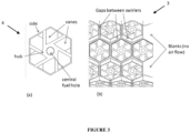
- the liner 2 of the combustor 1 in this design ( Figure 2 ) is partially or fully replaced with a "swirl mesh" 3 which is a set of hexagonal swirlers 4 meshed with each other in a hexagonal closed pack structure.
- Figure 3(a) shows an individual swirler 4, and Figure 3(b) , the proposed hexagonal closed pack structure of the swirler assembly.
- the size of the hexagons can be different based on the flow rate and velocity requirements of air, performance and manufacturability. While single swirler size for all the swirler units may help in assembly and manufacturability, smaller swirler size for the head end and larger sizes for the secondary zone might help in redistributing the air better.
- Some portion of the liner 2 may have blanks, which are regions on the liner wall that dont have swirler 4 and thus do not allow air into the combustor 1 through them.
- the distribution of blanks and hexagonal swirlers 4 is decided by the size of the engine and performance requirements like flow rates and combustion instability characteristics.
- Each swirler 4 has each of its multiple vanes starting from the hub and ending at the hexagonal rim.
- the adjacent hexagons either share a common side or have some gap between them.
- the swirl vanes and the sides can be of different thicknesses depending on performance requirements.
- the angle of the vanes and the hub diameter can be varied based on the requirement of the swirl number for flame holding.
- the manufacturing of the liner 2 can be done through rapid prototyping, injection molding, sheet forming/punching and/or six axis machining. There can also be a modular design where one can individually make a swirler 4, and then assemble them on the liner 2 thru spot welding on a thin sheet ( Figure 3 & 4 ).
- the second main design, the "Lean Direct Injection” in this disclosure is that the fuel is distributed across multiple locations of the liner 2. This causes the local fuel flow rate at the injection point to be low. It is well known that nonpremixed flame lengths are proportional to the fuel flow rates; therefore, this causes shorter flames.
- each of the swirler face can also be locally recessed in the center for the flame attached to the fuel injected there to act as a pilot flame to the other set of flames from the fuel injected at the peripheries between adjacent swirlers 4.
- the nozzle can be of varied sizes and designs depending on the required velocity and flow rate of the fuel, commensurate with the air flow rate and velocity. There are two different manifolds that supply fuel to the type 1 and type 2 injection locations.
- the fuel supply to the nozzles can be done in any of the following ways: 1) direct supply from radially inward tubes, 2) from manifolds to individual nozzles, 3) single/multiple fuel injection manifolds being thin tubes hidden upstream of the swirl vanes, minimally affecting the air flow and providing variability in the fuel distribution across different ports ( Figure 5 ) and 4 ) fuel tubes embedded in the swirl vanes that are thicker than usual, as mentioned above.
- the fuel tubes can be welded to the liner 2 and remachined for smooth finish.
- Fuel manifolds can feed fuel to both type 1&2 injection holes, or there could be separate fuel manifolds for each type of injection holes.
- the fuel manifolds can be fed by separate lines to have separate pressures for injection if required.
- the fuel injection in the secondary zone may also be decoupled from that in the primary zone, by having separate manifolds for that region.
- the secondary zone can have variation in the air flow incoming from the swirler distribution and also from the fuel injection variation through those swirlers 4.
- the fuel and air flow rates can be adjusted such that the combustor 1 operates in the required overall fuel lean conditions with the maximum flame temperature being the same as the turbine inlet temperature.
- the velocities in the swirl mesh 3 will be lower than existing designs due to larger opening in this design, also contributing to shorter flame lengths.
- Each swirler 4 induces a swirling flow, which causes local flow field similar to single swirler case. However, since there are multiple such swirlers 4 in this combustor 1, there is interaction between the vortices, causing highly turbulent flow field.
- the fuel injection at the center of the swirler provides flame stabilization whereas the fuel injection at the periphery between adjacent swirlers 4 enhances shear based fuel-air mixing. This improves combustion efficiency and decreases CO and unburnt hydrocarbon emissions.
- the overall short, lean, distributed flame decreases the flame temperature, thus decreasing the NOx formation. Since the flame temperature itself is targeted to be the turbine inlet temperature, there are no hot spots in the combustor 1 and the combustor exit temperature is uniform, leading to low radial pattern factor.
- the question of circumferential pattern factor does not even arise in the new design as it does not need the combustor 1 to be a set of burners in an annulus (example: eighteen swirl cups in an annulus), but distributed all around the circumference of the annular combustor 1.
- the flame holding is done by mixing as the fuel and air streams meet, and the flame will be diffusion like flame, which is very stable if the velocities of the two streams are similar.
- Diffusion flames are well known to respond less to acoustic excitations and therefore exhibit significantly lower amplitudes of combustion instability.
- the fuel supply system can be optimized to different operating conditions so as to spatially vary the flame strengths in such a way that the acoustic instability excited by one flame region is opposed by that caused by another flame region.
- the maximum temperature anywhere in the combustor 1 does not exceed the prescribed turbine inlet temperature that can be withstood by the turbine blades. Hence, the combustor 1 and liner walls need not be cooled. In addition, since circumferential pattern factor is zero, the thermal fatigue to the turbine blades is eliminated. Together, these two effects extend the life of the turbine blades, the most critical component in a gas turbine.
Landscapes
- Engineering & Computer Science (AREA)
- Chemical & Material Sciences (AREA)
- Combustion & Propulsion (AREA)
- Mechanical Engineering (AREA)
- General Engineering & Computer Science (AREA)
Claims (8)
- Verfahren zur direkten Kraftstoffverteilung in Gasturbinenbrennkammern, wobei die Brennkammer einen Mantel (2) aufweist, der teilweise oder vollständig durch ein Wirbelgitter (3) ersetzt ist, das ein Satz von sechseckigen Verwirbler (4) ist, die in einer sechseckigen geschlossenen Paketstruktur miteinander in Eingriff kommen, wobei das Verfahren die Verteilung von Luft durch verschiedene Stellen in dem Mantel (2) und die Verteilung von Kraftstoff über mehrere Stellen des Mantels (2) umfasst, und wobei die Kraftstoffeinspritzung von drei Typen sein kann:(a) eine Nabe jedes der Verwirbler (4) hat in der Mitte eine Düse zur Kraftstoffeinspritzung;(b) einige oder alle Ecken jedes der sechseckigen Verwirbler (4) haben eine Kraftstoffeinspritzdüse; oder(c) eine Kombination aus (a) und (b) oben.
- Verfahren nach Anspruch 1, wobei ein einzelner sechseckiger Verwirbler (4) einen Satz von Schaufeln aufweist, der an einer Nabe anfängt und an einer sechseckigen Krempe endet, wobei der Winkel der Schaufeln und der Nabendurchmesser vorzugsweise auf der Grundlage der Anforderung der Wirbelzahl für die Flammenhaltung variiert werden können.
- Verfahren nach Anspruch 1, wobei der Kraftstoff den Düsen entweder durch direkte Zufuhr aus radial nach innen gerichteten Rohren oder aus Verteilern zu einzelnen Düsen oder aus Einzel-/Mehrfach-Kraftstoffeinspritzverteilern, die die dünnen Rohre sind, die stromaufwärts der Wirbelschaufeln verborgen sind, zugeführt wird.
- Verfahren nach Anspruch 1, wobei das Wirbelgitter (3) so konfiguriert ist, dass die feste Masse zwischen den Verwirblern (4) minimiert wird.
- Gasturbinenbrennkammer mit einem Mantel (2), der teilweise oder vollständig durch ein Wirbelgitter (3) ersetzt ist, das ein Satz von sechseckigen Verwirblern (4) ist, die in einer sechseckigen geschlossenen Paketstruktur miteinander in Eingriff kommen, wobei die Gasturbinenbrennkammer so konfiguriert ist, dass sie Luft durch verschiedene Stellen in dem Mantel (2) verteilt und Kraftstoff über mehrere Stellen des Mantels (2) verteilt, und wobei die Gasturbinenbrennkammer ferner so konfiguriert ist, dass sie die Kraftstoffeinspritzung gemäß drei Typen durchführt:(a) eine Nabe jedes der Verwirbler (4) hat in der Mitte eine Düse für Kraftstoffeinspritzung;(b) einige oder alle Ecken jedes der sechseckigen Verwirbler (4) haben eine Kraftstoffeinspritzdüse; oder(c) eine Kombination aus (a) und (b) oben.
- Gasturbinenbrennkammer nach Anspruch 5, wobei ein einzelner sechseckiger Verwirbler (4) einen Satz von Schaufeln aufweist, der an einer Nabe anfängt und an einer sechseckigen Krempe endet, wobei der Winkel der Schaufeln und der Nabendurchmesser vorzugsweise auf der Grundlage der Anforderung der Wirbelzahl für die Flammenhaltung variiert werden können.
- Gasturbinenbrennkammer nach Anspruch 5, wobei die Gasturbinenbrennkammer so konfiguriert ist, dass der Kraftstoff den Düsen entweder durch direkte Zufuhr aus radial nach innen gerichteten Rohren oder aus Verteilern zu einzelnen Düsen oder aus Einzel-/Mehrfach-Kraftstoffeinspritzverteilern, die die dünnen Rohre sind, die stromaufwärts der Wirbelschaufeln verborgen sind, zugeführt wird.
- Gasturbinenbrennkammer nach Anspruch 5, wobei das Wirbelgitter (3) so konfiguriert ist, dass die feste Masse zwischen den Verwirblern (4) minimiert wird.
Applications Claiming Priority (2)
| Application Number | Priority Date | Filing Date | Title |
|---|---|---|---|
| IN201641024206 | 2016-07-15 | ||
| PCT/IN2017/050291 WO2018011827A1 (en) | 2016-07-15 | 2017-07-14 | A swirl mesh lean direct injection concept for distributed flame holding for low pollutant emissions and mitigation of combustion instability |
Publications (3)
| Publication Number | Publication Date |
|---|---|
| EP3485197A1 EP3485197A1 (de) | 2019-05-22 |
| EP3485197A4 EP3485197A4 (de) | 2020-02-19 |
| EP3485197B1 true EP3485197B1 (de) | 2023-03-22 |
Family
ID=60952026
Family Applications (1)
| Application Number | Title | Priority Date | Filing Date |
|---|---|---|---|
| EP17827143.3A Active EP3485197B1 (de) | 2016-07-15 | 2017-07-14 | Verfahren zur direkten kraftstoffverteilung in brennkammern von gasturbinen und brennkammer von gasturbinen |
Country Status (4)
| Country | Link |
|---|---|
| US (1) | US11300052B2 (de) |
| EP (1) | EP3485197B1 (de) |
| AU (1) | AU2017296362B2 (de) |
| WO (1) | WO2018011827A1 (de) |
Families Citing this family (3)
| Publication number | Priority date | Publication date | Assignee | Title |
|---|---|---|---|---|
| CN110762556B (zh) * | 2019-10-14 | 2020-12-04 | 哈尔滨工程大学 | 气液两相起爆装置 |
| CN113531584B (zh) * | 2020-04-15 | 2023-05-23 | 上海慕帆动力科技有限公司 | 燃气轮机的燃烧装置 |
| EP3988845B1 (de) * | 2020-09-30 | 2024-02-14 | Rolls-Royce plc | Direktkraftstoffeinspritzsystem |
Family Cites Families (18)
| Publication number | Priority date | Publication date | Assignee | Title |
|---|---|---|---|---|
| US3748853A (en) * | 1971-10-27 | 1973-07-31 | Nasa | Swirl can primary combustor |
| EP0204553B1 (de) | 1985-06-07 | 1989-06-07 | Ruston Gas Turbines Limited | Gasturbinenbrennkammer |
| US5879148A (en) | 1993-03-19 | 1999-03-09 | The Regents Of The University Of California | Mechanical swirler for a low-NOx, weak-swirl burner |
| JP3448041B2 (ja) * | 2001-09-26 | 2003-09-16 | 株式会社東芝 | パターン欠陥検査装置 |
| JP4670035B2 (ja) | 2004-06-25 | 2011-04-13 | 独立行政法人 宇宙航空研究開発機構 | ガスタービン燃焼器 |
| US8230687B2 (en) * | 2008-09-02 | 2012-07-31 | General Electric Company | Multi-tube arrangement for combustor and method of making the multi-tube arrangement |
| US8443611B2 (en) * | 2011-09-09 | 2013-05-21 | General Electric Company | System and method for damping combustor nozzle vibrations |
| US8950188B2 (en) * | 2011-09-09 | 2015-02-10 | General Electric Company | Turning guide for combustion fuel nozzle in gas turbine and method to turn fuel flow entering combustion chamber |
| JP6050821B2 (ja) * | 2011-09-22 | 2016-12-21 | ゼネラル・エレクトリック・カンパニイ | 燃焼器及び燃焼器に燃料を供給する方法 |
| US9310078B2 (en) * | 2012-10-31 | 2016-04-12 | General Electric Company | Fuel injection assemblies in combustion turbine engines |
| US9371997B2 (en) * | 2013-07-01 | 2016-06-21 | General Electric Company | System for supporting a bundled tube fuel injector within a combustor |
| US10330320B2 (en) * | 2013-10-24 | 2019-06-25 | United Technologies Corporation | Circumferentially and axially staged annular combustor for gas turbine engine |
| US9709279B2 (en) * | 2014-02-27 | 2017-07-18 | General Electric Company | System and method for control of combustion dynamics in combustion system |
| US9845956B2 (en) * | 2014-04-09 | 2017-12-19 | General Electric Company | System and method for control of combustion dynamics in combustion system |
| US9810148B2 (en) * | 2014-07-24 | 2017-11-07 | United Technologies Corporation | Self-cooled orifice structure |
| US10094568B2 (en) * | 2014-08-28 | 2018-10-09 | General Electric Company | Combustor dynamics mitigation |
| JP6440433B2 (ja) * | 2014-09-29 | 2018-12-19 | 川崎重工業株式会社 | 燃料噴射ノズル、燃料噴射モジュール、及びガスタービン |
| US10690350B2 (en) * | 2016-11-28 | 2020-06-23 | General Electric Company | Combustor with axially staged fuel injection |
-
2017
- 2017-07-14 WO PCT/IN2017/050291 patent/WO2018011827A1/en unknown
- 2017-07-14 EP EP17827143.3A patent/EP3485197B1/de active Active
- 2017-07-14 US US16/318,005 patent/US11300052B2/en active Active
- 2017-07-14 AU AU2017296362A patent/AU2017296362B2/en active Active
Also Published As
| Publication number | Publication date |
|---|---|
| EP3485197A1 (de) | 2019-05-22 |
| AU2017296362A2 (en) | 2020-01-30 |
| AU2017296362A1 (en) | 2019-03-07 |
| US20190301369A1 (en) | 2019-10-03 |
| AU2017296362B2 (en) | 2023-04-13 |
| EP3485197A4 (de) | 2020-02-19 |
| US11300052B2 (en) | 2022-04-12 |
| WO2018011827A1 (en) | 2018-01-18 |
Similar Documents
| Publication | Publication Date | Title |
|---|---|---|
| EP3433539B1 (de) | Verbrennungssystem mit panelkraftstoffinjektor | |
| US20090056336A1 (en) | Gas turbine premixer with radially staged flow passages and method for mixing air and gas in a gas turbine | |
| EP1985926B1 (de) | Brenngerät und brennverfahren | |
| US6240732B1 (en) | Fluid manifold | |
| EP1193449B1 (de) | Ringverwirbelungsanordnung | |
| US7509811B2 (en) | Multi-point staging strategy for low emission and stable combustion | |
| EP2290289B1 (de) | Gasturbinenbrennkammer mit verbesserter anordnung von kühlungslöchern | |
| EP2685172B1 (de) | Rohr-Ringkammer-Gasturbineneinheit mit gestufter Vormisch-Verbrennung | |
| EP2357413B1 (de) | Trockenverbrennungssystem mit niedrigem NOx-Ausstoss und mit Mitteln zur Beseitigung von Verbrennungslärm | |
| EP2532963B1 (de) | Rückfluss-Ringbrennkammer mit verringerten Emissionen | |
| JP5948489B2 (ja) | ガスタービン燃焼器 | |
| EP2722593B1 (de) | Rückfluss-Ringbrenner für verringerte Emissionen | |
| US8015814B2 (en) | Turbine engine having folded annular jet combustor | |
| US7878799B2 (en) | Multiple burner arrangement for operating a combustion chamber, and method for operating the multiple burner arrangement | |
| US20080083841A1 (en) | Fuel injector for a gas turbine engine combustion chamber | |
| EP2993404B1 (de) | Verdünnungsgas oder Luftmischer für eine Brennkammer einer Gasturbine | |
| US20130192245A1 (en) | Gas Turbine Combustor and Operating Method Thereof | |
| EP2966356B1 (de) | Sequentielle brennkammeranordnung mit einem mischer | |
| EP3485197B1 (de) | Verfahren zur direkten kraftstoffverteilung in brennkammern von gasturbinen und brennkammer von gasturbinen | |
| CN103930723A (zh) | 在燃气涡轮机上使用的、具有预混合的燃料和空气的切向环形燃烧器 | |
| EP2068076A2 (de) | Verbesserungen in oder in Bezug auf Brenner für ein Gasturbinentriebwerk | |
| EP1531305A1 (de) | Multipoint-Kraftstoffinjektor | |
| CZ2011784A3 (cs) | Nízkoemisní spalovací komora, zejména malých turbínových motoru |
Legal Events
| Date | Code | Title | Description |
|---|---|---|---|
| STAA | Information on the status of an ep patent application or granted ep patent |
Free format text: STATUS: THE INTERNATIONAL PUBLICATION HAS BEEN MADE |
|
| PUAI | Public reference made under article 153(3) epc to a published international application that has entered the european phase |
Free format text: ORIGINAL CODE: 0009012 |
|
| STAA | Information on the status of an ep patent application or granted ep patent |
Free format text: STATUS: REQUEST FOR EXAMINATION WAS MADE |
|
| 17P | Request for examination filed |
Effective date: 20190213 |
|
| AK | Designated contracting states |
Kind code of ref document: A1 Designated state(s): AL AT BE BG CH CY CZ DE DK EE ES FI FR GB GR HR HU IE IS IT LI LT LU LV MC MK MT NL NO PL PT RO RS SE SI SK SM TR |
|
| AX | Request for extension of the european patent |
Extension state: BA ME |
|
| DAV | Request for validation of the european patent (deleted) | ||
| DAX | Request for extension of the european patent (deleted) | ||
| RIC1 | Information provided on ipc code assigned before grant |
Ipc: F23R 3/02 20060101AFI20200109BHEP |
|
| A4 | Supplementary search report drawn up and despatched |
Effective date: 20200117 |
|
| STAA | Information on the status of an ep patent application or granted ep patent |
Free format text: STATUS: EXAMINATION IS IN PROGRESS |
|
| 17Q | First examination report despatched |
Effective date: 20201021 |
|
| STAA | Information on the status of an ep patent application or granted ep patent |
Free format text: STATUS: EXAMINATION IS IN PROGRESS |
|
| STAA | Information on the status of an ep patent application or granted ep patent |
Free format text: STATUS: EXAMINATION IS IN PROGRESS |
|
| GRAP | Despatch of communication of intention to grant a patent |
Free format text: ORIGINAL CODE: EPIDOSNIGR1 |
|
| STAA | Information on the status of an ep patent application or granted ep patent |
Free format text: STATUS: GRANT OF PATENT IS INTENDED |
|
| INTG | Intention to grant announced |
Effective date: 20221011 |
|
| RIN1 | Information on inventor provided before grant (corrected) |
Inventor name: SHANMUGAPRABHU, S. Inventor name: DEEPIKA, V. Inventor name: RAJABHARATHI, N. Inventor name: PREETHI, R.S Inventor name: CHAKRAVARTHY, S.R Inventor name: MURUGANANDAM, T.M |
|
| RAP1 | Party data changed (applicant data changed or rights of an application transferred) |
Owner name: AEROSTROVILOS ENERGY PRIVATE LIMITED Owner name: INDIAN INSTITUTE OF TECHNOLOGY (IIT MADRAS) |
|
| GRAS | Grant fee paid |
Free format text: ORIGINAL CODE: EPIDOSNIGR3 |
|
| GRAA | (expected) grant |
Free format text: ORIGINAL CODE: 0009210 |
|
| STAA | Information on the status of an ep patent application or granted ep patent |
Free format text: STATUS: THE PATENT HAS BEEN GRANTED |
|
| AK | Designated contracting states |
Kind code of ref document: B1 Designated state(s): AL AT BE BG CH CY CZ DE DK EE ES FI FR GB GR HR HU IE IS IT LI LT LU LV MC MK MT NL NO PL PT RO RS SE SI SK SM TR |
|
| REG | Reference to a national code |
Ref country code: GB Ref legal event code: FG4D |
|
| REG | Reference to a national code |
Ref country code: CH Ref legal event code: EP |
|
| REG | Reference to a national code |
Ref country code: DE Ref legal event code: R096 Ref document number: 602017067062 Country of ref document: DE |
|
| REG | Reference to a national code |
Ref country code: IE Ref legal event code: FG4D |
|
| REG | Reference to a national code |
Ref country code: AT Ref legal event code: REF Ref document number: 1555510 Country of ref document: AT Kind code of ref document: T Effective date: 20230415 |
|
| REG | Reference to a national code |
Ref country code: NL Ref legal event code: FP |
|
| REG | Reference to a national code |
Ref country code: LT Ref legal event code: MG9D |
|
| REG | Reference to a national code |
Ref country code: SE Ref legal event code: TRGR |
|
| PG25 | Lapsed in a contracting state [announced via postgrant information from national office to epo] |
Ref country code: RS Free format text: LAPSE BECAUSE OF FAILURE TO SUBMIT A TRANSLATION OF THE DESCRIPTION OR TO PAY THE FEE WITHIN THE PRESCRIBED TIME-LIMIT Effective date: 20230322 Ref country code: NO Free format text: LAPSE BECAUSE OF FAILURE TO SUBMIT A TRANSLATION OF THE DESCRIPTION OR TO PAY THE FEE WITHIN THE PRESCRIBED TIME-LIMIT Effective date: 20230622 Ref country code: LV Free format text: LAPSE BECAUSE OF FAILURE TO SUBMIT A TRANSLATION OF THE DESCRIPTION OR TO PAY THE FEE WITHIN THE PRESCRIBED TIME-LIMIT Effective date: 20230322 Ref country code: LT Free format text: LAPSE BECAUSE OF FAILURE TO SUBMIT A TRANSLATION OF THE DESCRIPTION OR TO PAY THE FEE WITHIN THE PRESCRIBED TIME-LIMIT Effective date: 20230322 Ref country code: HR Free format text: LAPSE BECAUSE OF FAILURE TO SUBMIT A TRANSLATION OF THE DESCRIPTION OR TO PAY THE FEE WITHIN THE PRESCRIBED TIME-LIMIT Effective date: 20230322 |
|
| REG | Reference to a national code |
Ref country code: AT Ref legal event code: MK05 Ref document number: 1555510 Country of ref document: AT Kind code of ref document: T Effective date: 20230322 |
|
| PG25 | Lapsed in a contracting state [announced via postgrant information from national office to epo] |
Ref country code: GR Free format text: LAPSE BECAUSE OF FAILURE TO SUBMIT A TRANSLATION OF THE DESCRIPTION OR TO PAY THE FEE WITHIN THE PRESCRIBED TIME-LIMIT Effective date: 20230623 Ref country code: FI Free format text: LAPSE BECAUSE OF FAILURE TO SUBMIT A TRANSLATION OF THE DESCRIPTION OR TO PAY THE FEE WITHIN THE PRESCRIBED TIME-LIMIT Effective date: 20230322 |
|
| PGFP | Annual fee paid to national office [announced via postgrant information from national office to epo] |
Ref country code: NL Payment date: 20230726 Year of fee payment: 7 |
|
| PG25 | Lapsed in a contracting state [announced via postgrant information from national office to epo] |
Ref country code: SM Free format text: LAPSE BECAUSE OF FAILURE TO SUBMIT A TRANSLATION OF THE DESCRIPTION OR TO PAY THE FEE WITHIN THE PRESCRIBED TIME-LIMIT Effective date: 20230322 Ref country code: RO Free format text: LAPSE BECAUSE OF FAILURE TO SUBMIT A TRANSLATION OF THE DESCRIPTION OR TO PAY THE FEE WITHIN THE PRESCRIBED TIME-LIMIT Effective date: 20230322 Ref country code: PT Free format text: LAPSE BECAUSE OF FAILURE TO SUBMIT A TRANSLATION OF THE DESCRIPTION OR TO PAY THE FEE WITHIN THE PRESCRIBED TIME-LIMIT Effective date: 20230724 Ref country code: ES Free format text: LAPSE BECAUSE OF FAILURE TO SUBMIT A TRANSLATION OF THE DESCRIPTION OR TO PAY THE FEE WITHIN THE PRESCRIBED TIME-LIMIT Effective date: 20230322 Ref country code: EE Free format text: LAPSE BECAUSE OF FAILURE TO SUBMIT A TRANSLATION OF THE DESCRIPTION OR TO PAY THE FEE WITHIN THE PRESCRIBED TIME-LIMIT Effective date: 20230322 Ref country code: AT Free format text: LAPSE BECAUSE OF FAILURE TO SUBMIT A TRANSLATION OF THE DESCRIPTION OR TO PAY THE FEE WITHIN THE PRESCRIBED TIME-LIMIT Effective date: 20230322 |
|
| PGFP | Annual fee paid to national office [announced via postgrant information from national office to epo] |
Ref country code: GB Payment date: 20230713 Year of fee payment: 7 Ref country code: CH Payment date: 20230801 Year of fee payment: 7 |
|
| PG25 | Lapsed in a contracting state [announced via postgrant information from national office to epo] |
Ref country code: SK Free format text: LAPSE BECAUSE OF FAILURE TO SUBMIT A TRANSLATION OF THE DESCRIPTION OR TO PAY THE FEE WITHIN THE PRESCRIBED TIME-LIMIT Effective date: 20230322 Ref country code: PL Free format text: LAPSE BECAUSE OF FAILURE TO SUBMIT A TRANSLATION OF THE DESCRIPTION OR TO PAY THE FEE WITHIN THE PRESCRIBED TIME-LIMIT Effective date: 20230322 Ref country code: IS Free format text: LAPSE BECAUSE OF FAILURE TO SUBMIT A TRANSLATION OF THE DESCRIPTION OR TO PAY THE FEE WITHIN THE PRESCRIBED TIME-LIMIT Effective date: 20230722 |
|
| PGFP | Annual fee paid to national office [announced via postgrant information from national office to epo] |
Ref country code: SE Payment date: 20230726 Year of fee payment: 7 Ref country code: FR Payment date: 20230725 Year of fee payment: 7 Ref country code: DE Payment date: 20230726 Year of fee payment: 7 |
|
| REG | Reference to a national code |
Ref country code: DE Ref legal event code: R097 Ref document number: 602017067062 Country of ref document: DE |
|
| PLBE | No opposition filed within time limit |
Free format text: ORIGINAL CODE: 0009261 |
|
| STAA | Information on the status of an ep patent application or granted ep patent |
Free format text: STATUS: NO OPPOSITION FILED WITHIN TIME LIMIT |
|
| PG25 | Lapsed in a contracting state [announced via postgrant information from national office to epo] |
Ref country code: SI Free format text: LAPSE BECAUSE OF FAILURE TO SUBMIT A TRANSLATION OF THE DESCRIPTION OR TO PAY THE FEE WITHIN THE PRESCRIBED TIME-LIMIT Effective date: 20230322 Ref country code: DK Free format text: LAPSE BECAUSE OF FAILURE TO SUBMIT A TRANSLATION OF THE DESCRIPTION OR TO PAY THE FEE WITHIN THE PRESCRIBED TIME-LIMIT Effective date: 20230322 Ref country code: CZ Free format text: LAPSE BECAUSE OF FAILURE TO SUBMIT A TRANSLATION OF THE DESCRIPTION OR TO PAY THE FEE WITHIN THE PRESCRIBED TIME-LIMIT Effective date: 20230322 |
|
| 26N | No opposition filed |
Effective date: 20240102 |
|
| PG25 | Lapsed in a contracting state [announced via postgrant information from national office to epo] |
Ref country code: MC Free format text: LAPSE BECAUSE OF FAILURE TO SUBMIT A TRANSLATION OF THE DESCRIPTION OR TO PAY THE FEE WITHIN THE PRESCRIBED TIME-LIMIT Effective date: 20230322 |
|
| PG25 | Lapsed in a contracting state [announced via postgrant information from national office to epo] |
Ref country code: MC Free format text: LAPSE BECAUSE OF FAILURE TO SUBMIT A TRANSLATION OF THE DESCRIPTION OR TO PAY THE FEE WITHIN THE PRESCRIBED TIME-LIMIT Effective date: 20230322 |
|
| REG | Reference to a national code |
Ref country code: BE Ref legal event code: MM Effective date: 20230731 |
|
| PG25 | Lapsed in a contracting state [announced via postgrant information from national office to epo] |
Ref country code: LU Free format text: LAPSE BECAUSE OF NON-PAYMENT OF DUE FEES Effective date: 20230714 |
|
| PG25 | Lapsed in a contracting state [announced via postgrant information from national office to epo] |
Ref country code: LU Free format text: LAPSE BECAUSE OF NON-PAYMENT OF DUE FEES Effective date: 20230714 |
|
| REG | Reference to a national code |
Ref country code: IE Ref legal event code: MM4A |