EP2067622A1 - Liquid cartridge and recording system - Google Patents
Liquid cartridge and recording system Download PDFInfo
- Publication number
- EP2067622A1 EP2067622A1 EP07828811A EP07828811A EP2067622A1 EP 2067622 A1 EP2067622 A1 EP 2067622A1 EP 07828811 A EP07828811 A EP 07828811A EP 07828811 A EP07828811 A EP 07828811A EP 2067622 A1 EP2067622 A1 EP 2067622A1
- Authority
- EP
- European Patent Office
- Prior art keywords
- section
- light
- liquid
- ink
- remaining
- Prior art date
- Legal status (The legal status is an assumption and is not a legal conclusion. Google has not performed a legal analysis and makes no representation as to the accuracy of the status listed.)
- Granted
Links
- 239000007788 liquid Substances 0.000 title claims abstract description 213
- 230000000903 blocking effect Effects 0.000 claims abstract description 71
- 230000007423 decrease Effects 0.000 claims abstract description 49
- 230000004044 response Effects 0.000 claims abstract description 17
- 230000007246 mechanism Effects 0.000 claims description 57
- 230000008859 change Effects 0.000 claims description 20
- 238000003780 insertion Methods 0.000 claims description 10
- 230000037431 insertion Effects 0.000 claims description 10
- 238000006073 displacement reaction Methods 0.000 claims description 6
- 230000002093 peripheral effect Effects 0.000 claims description 3
- 230000001678 irradiating effect Effects 0.000 claims description 2
- 238000001514 detection method Methods 0.000 abstract description 204
- 230000003287 optical effect Effects 0.000 description 24
- 239000000463 material Substances 0.000 description 18
- 230000003247 decreasing effect Effects 0.000 description 12
- 238000010276 construction Methods 0.000 description 6
- 230000005484 gravity Effects 0.000 description 5
- 230000001154 acute effect Effects 0.000 description 4
- 230000006870 function Effects 0.000 description 4
- 239000011347 resin Substances 0.000 description 4
- 229920005989 resin Polymers 0.000 description 4
- 238000004891 communication Methods 0.000 description 3
- 230000002441 reversible effect Effects 0.000 description 3
- 230000004308 accommodation Effects 0.000 description 2
- 230000005540 biological transmission Effects 0.000 description 2
- LNEPOXFFQSENCJ-UHFFFAOYSA-N haloperidol Chemical compound C1CC(O)(C=2C=CC(Cl)=CC=2)CCN1CCCC(=O)C1=CC=C(F)C=C1 LNEPOXFFQSENCJ-UHFFFAOYSA-N 0.000 description 2
- 238000000034 method Methods 0.000 description 2
- 238000000926 separation method Methods 0.000 description 2
- 238000012986 modification Methods 0.000 description 1
- 230000004048 modification Effects 0.000 description 1
- 230000000149 penetrating effect Effects 0.000 description 1
- 230000000717 retained effect Effects 0.000 description 1
Images


Classifications
-
- B—PERFORMING OPERATIONS; TRANSPORTING
- B41—PRINTING; LINING MACHINES; TYPEWRITERS; STAMPS
- B41J—TYPEWRITERS; SELECTIVE PRINTING MECHANISMS, i.e. MECHANISMS PRINTING OTHERWISE THAN FROM A FORME; CORRECTION OF TYPOGRAPHICAL ERRORS
- B41J2/00—Typewriters or selective printing mechanisms characterised by the printing or marking process for which they are designed
- B41J2/005—Typewriters or selective printing mechanisms characterised by the printing or marking process for which they are designed characterised by bringing liquid or particles selectively into contact with a printing material
- B41J2/01—Ink jet
- B41J2/17—Ink jet characterised by ink handling
- B41J2/175—Ink supply systems ; Circuit parts therefor
- B41J2/17566—Ink level or ink residue control
- B41J2002/17573—Ink level or ink residue control using optical means for ink level indication
-
- B—PERFORMING OPERATIONS; TRANSPORTING
- B41—PRINTING; LINING MACHINES; TYPEWRITERS; STAMPS
- B41J—TYPEWRITERS; SELECTIVE PRINTING MECHANISMS, i.e. MECHANISMS PRINTING OTHERWISE THAN FROM A FORME; CORRECTION OF TYPOGRAPHICAL ERRORS
- B41J2/00—Typewriters or selective printing mechanisms characterised by the printing or marking process for which they are designed
- B41J2/005—Typewriters or selective printing mechanisms characterised by the printing or marking process for which they are designed characterised by bringing liquid or particles selectively into contact with a printing material
- B41J2/01—Ink jet
- B41J2/17—Ink jet characterised by ink handling
- B41J2/175—Ink supply systems ; Circuit parts therefor
- B41J2/17566—Ink level or ink residue control
- B41J2002/17576—Ink level or ink residue control using a floater for ink level indication
Definitions
- the present invention relates to a liquid cartridge, more particularly to a liquid cartridge mountable in a recording device for supplying liquid thereto, and also relates to a recording system including the liquid cartridge.
- a separate liquid cartridge is often used for supplying liquid to the recoding device. If there is a small amount of liquid left in the liquid cartridge when a user replaces the liquid cartridge, the liquid in the liquid cartridge will soon become empty if a large amount of printing is performed right after the replacement. In such a case, the user needs to replace the liquid cartridge again in the middle of the printing operation. In order to avid such a situation, there is a need for a configuration that detects whether the amount of liquid remaining in the liquid cartridge is small, and, if so, warns that the cartridge needs to be replaced soon.
- patent document 1 discloses that a float is provided in a liquid cartridge so as to be dislocated in accordance with a decrease in the amount of liquid in the liquid cartridge.
- a degree of displacement of the float in a horizontal direction can be detected by a reflective optical sensor that moves horizontally relative to the liquid cartridge. This construction can detect how much liquid is left in the liquid cartridge as needed.
- a plurality of optical sensors can be employed with respect to the horizontal direction, instead of moving an optical sensor, in order to detect residual amounts of liquid as in patent document 1. With these methods, detecting amounts of liquid left in a liquid cartridge right after the liquid cartridge is mounted may determine whether the remaining amount of liquid in the liquid cartridge is little.
- an optical sensor is configured to move relative to a liquid cartridge as disclosed in patent document 1
- dimensions of a recoding device tend to be large.
- providing a plurality of optical sensors leads to an increase in the number of parts.
- a liquid cartridge employing the above-described detecting methods necessitates an increase in costs of a recoding device.
- a liquid cartridge according to the present invention is mountable in a recording device provided with a mount section in which the liquid cartridge is mounted through an insertion opening from a predetermined mounting direction and light detecting means including a light emitting section that emits light to a direction orthogonal to the mounting direction and a light receiving section that receives the emitted light from the light emitting section.
- the liquid cartridge includes a liquid accommodating chamber that accommodates liquid, an outlet that introduces liquid to outside, and a remaining-amount detecting mechanism provided within the liquid accommodating chamber for detecting remaining amounts of liquid.
- the remaining-amount detecting mechanism includes a float that follows liquid surface of the liquid accommodated in the liquid accommodating chamber and is dislocated in accordance with decrease in the liquid, and an irradiated section that is dislocated along a predetermined path in conjunction with displacement of the float, the irradiated section including a first section and a second section, the first section directing the emitted light toward the light receiving section, the second section blocking the emitted light, the first section and the second section being arranged alternately.
- the irradiated section is configured such that at least one of the number of times the first section intersects with the emitted light and the number of times the second section intersects with the emitted light can change depending on where the irradiated section is located along the predetermined path, from when the liquid cartridge is inserted through the insertion opening until when the liquid cartridge has mounted in the mount section.
- a recoding system includes a liquid cartridge and a recording device in which the liquid cartridge is mounted, the recording system ejecting liquid supplied from the liquid cartridge onto an ejection medium so that the liquid adheres to the ejection medium.
- the recording device includes a mount section in which the liquid cartridge is mounted from a predetermined mounting direction through an insertion opening, and light detecting means that includes a light emitting section that emits light to a direction orthogonal to the mounting direction and a light receiving section that receives the emitted light from the light emitting section, the light detecting means being disposed at a position where the light emitting section and the light receiving section can interpose a portion of the liquid cartridge mounted in the mount section.
- the liquid cartridge includes a liquid accommodating chamber that accommodates liquid, an outlet that introduces the liquid to outside, and a remaining-amount detecting mechanism provided within the liquid accommodating chamber for detecting residual amounts of liquid.
- the remaining-amount detecting mechanism includes a float that follows liquid surface of the liquid accommodated in the liquid accommodating chamber and is dislocated in accordance with decrease in the liquid, and an irradiated section that is dislocated along a predetermined path in conjunction with displacement of the float, the irradiated section including a first section and a second section, the first section directing the emitted light toward the light receiving section, the second section blocking the emitted light, the first section and the second section being arranged alternately.
- the irradiated section is configured such that at least one of the number of times the first section intersects with the irradiated light and the number of times the second section intersects with the irradiated light can change depending on where the irradiated section is located along the predetermined path, from when the liquid cartridge is inserted through the insertion opening until when the liquid cartridge has mounted in the mount section.
- the remaining-amount detecting mechanism is dislocated along a predetermined path in conjunction with displacement of the float in accordance with decrease in the liquid.
- the irradiated section is configured such that at least one of the number of times the first section intersects with the emitted light and the number of times the second section intersects with the emitted light can change depending on where the irradiated section is located along the predetermined path. Accordingly, at which position on the predetermined path the irradiated section is located can be detected by detecting the irradiated light at the light receiving section and counting the number of times either the first section or the second section intersects with the light. That is, amounts of liquid left in the liquid cartridge are acquired.
- the remaining-amount detecting mechanism is preferably provided with an arm section that connects the float and the irradiated section, and a pivoting mechanism that pivotably movably supports the arm section.
- the arm section connects the irradiated section and a pivot point of the pivot mechanism, the remaining-amount detecting mechanism can be made compact, compared with a case in which the remaining-amount detecting mechanism is formed of a disk-shaped member.
- the distance between the irradiated section and the pivot point can be made longer by simply making the length of the arm longer, thereby enabling the remaining-amount detecting mechanism to be still retained compact.
- the remaining-amount detecting mechanism further includes a restricting mechanism that restricts movements of the float and the irradiated section to the prescribed path, and the restricting mechanism restricts pivotal movement of the arm section along a direction in which the float tries to move up because of the liquid accommodated in the liquid accommodating chamber.
- the arm is configured not to pivotally move when a sufficient amount of liquid is left, but to start making a pivotal movement when the liquid has decreased to a certain amount.
- the irradiated section is dislocated from a leading side to a trailing side in the mounting direction as the irradiated section moves along the predetermined path in accordance with the decrease in liquid accommodated in the liquid accommodating chamber.
- the remaining-amount detecting mechanism can also be configured such that changes in the remaining amount of liquid after the liquid cartridge has been mounted can be detected by positional changes of the irradiated section.
- single remaining-amount detecting mechanism allows detecting both the residual amounts of liquid when mounted and the changes in the amounts of liquid thereafter.
- the predetermined mounting direction is a horizontal direction
- the irradiated section is always located at a position above the pivot point of the pivot mechanism while the irradiated section moves along the predetermined path.
- the irradiated section preferably includes at least one first section and at least two second sections, and the first and second sections are preferably arranged on a straight line drawn by the emitted light irradiating the irradiated section, regardless of where the first and the second sections are located along the predetermined path.
- the first section and the second section can be arranged on the straight line along which the light irradiates, i.e., the straight line along the mounting direction, regardless of the residual amounts of liquid in the liquid accommodating chamber.
- the irradiated section is configured to be dislocated in the mounting direction as the liquid decreases. Accordingly, at least either the number of times the first section intersects or the number of times the second section intersects can change reliably in accordance with decrease of the liquid, when the liquid cartridge is being mounted.
- the remaining-amount detecting mechanism may include a remaining-amount detecting member and a pivot mechanism that pivotably movably supports the remaining-amount detecting member, the remaining-amount detecting member integrally including the float and the irradiated section.
- the first section and the second section may be arranged along a circumference of the pivot mechanism having the pivot point as a center, and may also be arranged alternately in a radial direction passing through the pivot center, the first section extending longer or shorter as the first section is located closer to the pivot center.
- the light reliably intersects with the first section and the second section.
- the first section extends along the circumference having the pivot center as its center, and length of the first section with respect to the extending direction is arranged to be longer or shorter, according to the distance from the pivot point.
- the remaining-amount detecting member pivotally moves in the circumferential direction in response to the decrease of liquid.
- each of one ends of the first sections is preferably located at a position the same as each other with respect to the circumferential direction of the pivot mechanism having the pivot point as a center, and first sections preferably extend from the one ends along a direction identical to each other with respect to the circumferential direction.
- each of one ends of the first sections is located at the same position with respect to the circumferential direction, and each of the first sections extends in the same direction.
- the first sections are formed so as to become longer or shorter in accordance with the distance from the pivot point. Accordingly, in this liquid cartridge, as the liquid decreases, the number of times the first sections intersect with the light can be made fewer or greater.
- the remaining-amount detecting member is preferably formed in a disk shape having the pivot point of the pivot mechanism as a center. If the remaining-amount detecting member has a shape other than a disk, such as a rectangular shape for example, the remaining-amount detecting member necessarily has a planar end surface. If the end surface moves past the liquid surface when the remaining-amount detecting member pivotally moves, air bubbles may adhere to the end surface. Adherence of air bubbles to the end surface prevents the remaining-amount detecting member from moving smoothly, thereby leading to unstable detection of the residual amount of the liquid.
- the remaining-amount detecting member has a disk shape, no planar end surface is formed as in the rectangular shaped remaining-amount detecting member. Hence, air bubbles do not easily adhere when the remaining-amount detecting member pivotally moves, thereby leading to stable detection of the residual amount of liquid.
- the irradiated section is further formed with a third section that directs the emitted light toward the light receiving section, and the third section is located at a position separated from or adjacent to, and rearward of the first section extending the longest with respect to a moving direction of the remaining-amount detecting member in response to the decrease in the liquid within the liquid accommodating chamber, and extends from an peripheral end of the remaining-amount detecting member to a position at which the emitted light is irradiated.
- the third section is formed at a position rearward of the first section with respect to the moving direction of the remaining-amount detecting member in response to the decrease in the liquid, i.e., at a position at which the light is irradiated when the liquid has decreased to a minimum amount.
- the third section extends from the peripheral end of the remaining-amount detecting member to a position at which the emitted light is irradiated.
- the remaining-amount detecting mechanism may be provided with a remaining-amount detecting member that integrally includes the float and the irradiated section, and a pivot mechanism that pivotably movably supports the remaining-amount detecting member.
- the first section and the second section may be arranged alternately in the circumferential direction of the pivot mechanism having the pivot point as a center, and the first section may have an elongated shape extending in a direction, the direction having a larger or smaller angle relative to a straight line passing through the pivot point, as the first section moves in the circumferential direction.
- the irradiation position of the light is configured to be movable relative to the remaining-amount detecting member in the radial direction thereof.
- the first section is configured to have a larger or smaller angle relative to the straight line passing through the pivot point, as the first section moves in the circumferential direction. Therefore, each of the first sections can be aligned with each other with respect to the radial direction in the remaining-amount detecting member. Hence, how many times the light intersects with the first sections at the time of mounting can change reliably as the liquid decreases.
- each of one ends of the first sections is preferably located at a position separated from the pivot point by a distance identical to each other, and other ends of the first sections are preferably arranged such that the number of times the first sections intersect with the emitted light increases or decreases in accordance with the decrease of the liquid within the liquid accommodating chamber from when the liquid cartridge is inserted through the insertion opening until when the liquid cartridge has mounted in the mount section.
- the liquid cartridge reliably allows to detect that smaller amounts of liquid is left as the number of times the light intersects with the first section is fewer or greater.
- the irradiated section has a plurality of first sections, and the plurality of the first sections is formed in the irradiated section so as to intersect with a circumference of a circle passing through a point at which the emitted light is irradiated and having the pivot point as a center when the liquid cartridge is mounted in the recording device.
- the irradiation position of light is configured to move along the circumference about the pivot point in accordance with the decrease of the liquid.
- the light intersects with the plurality of the first sections as the liquid decreases.
- current residual amount of liquid can be obtained by counting how many first sections have intersected with the light by present.
- the remaining-amount detecting mechanism may further include a restricting mechanism that restricts the movement of the float and the irradiated section to move linearly along a moving direction, the moving direction intersecting with the mounting direction and the direction of the emitted light, and the first section may extend along the moving direction, and the first section and the second section may be arranged in the mounting direction.
- a plurality of the first sections having a length different from each other is preferably arranged in the mounting direction.
- Fig. 1 is a view showing a schematic configuration of a printer system 1.
- the printer system 1 includes an ink cartridge 10 and an inkjet printer 20.
- the 20 (hereinafter referred to as "printer 20") includes a control section 22, a notifying section 29, an inkjet head 23, a conveying unit 24, and an accommodating case 30.
- the control section 22 controls operations of the printer 20.
- the notifying section 29 notifies a user of the printer 20 of various information on operation status of the printer 20, in accordance with instructions of the control section 22.
- the notifying section 29 may include a display so that various information can be displayed on the display to notify the user of the information.
- the inkjet head 23 has a plurality of nozzles 23a.
- An ink channel (not shown) is formed inside the inkjet head 23. Ink supplied from the ink channel is ejected downward from the nozzles 23a.
- the conveying unit 24 conveys printing paper P to a position below the inkjet head 23. The ink ejected from the inkjet head 23 falls onto the printing paper P conveyed by the conveying unit 24.
- the control section 22 controls ink ejection from the inkjet head 23 and conveyance of the printing paper P by the conveying unit 24, based on image data transmitted from a personal computer or the like connected to the printer 20. Thus, the printer 20 forms an image corresponding to the image data on the printing paper P.
- the accommodating case 30 is a case that accommodates the ink cartridge 110.
- An accommodating space 32 (mount section) having substantially a rectangular parallelepiped shape is formed within the accommodating case 30.
- the ink cartridge 110 is mounted in and dismounted from the accommodating space 32 along a direction shown by an arrow B.
- Concave sections 34 are formed on an inner surface of the accommodating case 30 that defines the accommodating space 32. The concave sections 34 extend from an opening of the accommodating space 32 to the far side of the accommodating space 32 along the direction B.
- the accommodating case 30 includes an optical sensor section 31, an ink inlet port 33, and a lid section 35.
- the optical sensor section 31 is provided such that the optical sensor section 31 is exposed to the accommodating space 32 within the accommodating case 30.
- the ink inlet port 33 is an opening connecting to an ink outlet port 112 of the ink cartridge 110 so that ink flowing out of the ink outlet port 112 can flow into the ink inlet port 33, when the ink cartridge 110 is mounted in the accommodating case 30.
- the ink inlet port 33 is in communication with the ink channel within the inkjet head 23 via an ink tube 25. Thus, the ink from the ink cartridge 110 is introduced to the ink channel inside the inkjet head 23.
- the lid section 35 opens and closes the opening serving as an entrance/exit of the accommodating case 30, and is provided to the accommodating case 30 so as to be capable of swinging in a direction of an arrow A.
- the lid section 35 opens the opening of the accommodating case 30 when the ink cartridge 110 is mounted in or dismounted from the accommodating case 30, and closes the opening of the accommodating case 30 once the ink cartridge 110 is mounted.
- the ink cartridge 110 has substantially a rectangular parallelepiped shape that is approximately the same as the accommodating space 32, and is slightly smaller than the accommodating space 32.
- Convex sections 113 are formed on a side surface of the ink cartridge 110.
- the convex sections 113 have shapes that are substantially the same as the concave sections 34 formed in the accommodating case 30, and have sizes that can fit in the concave sections 34.
- the ink cartridge 110 has an ink outlet port 112. When the ink cartridge 110 is being mounted in or dismounted from the accommodating case 30, the ink cartridge 110 is slid along the direction of the arrow B while the convex sections 113 of the ink cartridge 110 and the concave sections 34 of the accommodating case 30 are coupled to each other.
- the convex sections 113 and the concave sections 34 are guide members that cause the ink cartridge 110 to move along the detachable direction B.
- the ink outlet port 112 is in communication with the ink inlet port 33.
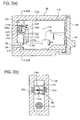
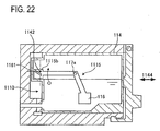
- Figs. 2(a) and 2(b) are views showing an internal configuration of the ink cartridge 110 and a configuration of the accommodating case 30.
- the ink cartridge 110 takes a mount attitude in which the ink cartridge 110 is mounted in the accommodating case 30.
- the attitude of the ink cartridge when mounted in the accommodating case as shown in Fig. 2 is referred to as "mounted attitude”.
- Fig. 2(b) is a cross-sectional view taken along a line IIB-IIB in Fig. 2(a) .
- the ink cartridge 110 has a cartridge casing 114 (hereinafter referred to as "casing 114").
- the casing 114 is made of a material having light transmissive characteristics, such as a translucent resin material.
- a hollow ink accommodating chamber 114c is formed within the casing 114, and ink 99 is accommodated in the ink accommodating chamber 114c. That is, the casing 114 defines the ink accommodating chamber 114c (liquid accommodating chamber) that accommodates ink.
- the casing 114 is formed in a cube shape as a whole.
- the casing 114 has a convex portion 114d protruding leftward threrefrom in Fig. 2(a) .
- the inner space of the convex portion 114d constitutes a portion of the ink accommodating chamber 114c.
- the ink accommodating chamber 114c is in communication with an ink outlet section 39 that allows ink to flow to the outside via a passage 38.
- An open/close mechanism (not shown) that opens and closes the ink outlet section 39 is provided within the passage 38. This open/close mechanism normally closes the ink outlet section 39, and opens the ink outlet section 39 when the ink outlet section 39 is connected to the ink inlet port 33 of the accommodating case 30.
- a remaining-amount detecting mechanism is provided within the ink accommodating chamber 114c for detecting residual amounts of liquid 99.
- the remaining-amount detecting mechanism includes a detection member 115 and a float member 116.
- the detection member 15 is a plate-shaped member made of a material having light blocking characteristics, and includes an arm section 115a and an irradiated section 115b.
- the arm section 115a has two corner sections 115e and 115f at each of which the arm section 115a is bent approximately perpendicularly.
- the irradiated section 115b is fixed to an end of the arm section 115a, whereas the float member 116 is fixed to the other end.
- the float member 16 is made of a material of resin or the like, and so configured that its mass per unit volume is smaller than the density of ink 99.
- the float member 116 may be made of a material of which specific gravity is smaller than ink, or may be formed as a hollow body having a cavity inside if the float member 116 is made of a material of which specific gravity is greater than ink.
- the irradiated section 115b has generally a square shape.
- a generally rectangular-shaped slit 161 is formed in the irradiated section 115b.
- the slit 161 extends downward from an upper end of the irradiated section 115b to a position close to a lower end of the irradiated section 115b in Fig. 2(a) .
- the slit 161 is arranged at a position slightly leftward of the center of the irradiated section 115b with respect to the left-right direction of Fig. 2 .
- light blocking sections 162a and 162b are formed such that the slit 161 is interposed between the light blocking sections 162a and 162b.
- the slit 161 is a portion through which light from a light emitting element 31a transmits (a portion that directs incident light toward a light receiving element; first section), whereas the light blocking sections 162a and 162b are portions (second section) that block light from the light emitting element 31a.
- the arm section 115a is pivotably supported by a pivot mechanism.
- the pivot mechanism is configured of a pivot shaft 117a and a bearing (not shown).
- the pivot shaft 117a is fixed to one of the bent corner sections in the arm section 115a, i.e., the corner section 115e.
- the pivot shaft 117a is pviotably movably supported by the bearing. This configuration allows the arm section 115a to pivotally move about the pivot shaft 117a.
- the pivot shaft 117a is supported at a position close to the lower section of the left inner wall surface of the ink accommodating chamber 114c.
- the position at which the pivot shaft 117a is supported is adjusted such that the float member 116 is arranged near the bottom surface within the ink accommodating chamber 114c in the up-down direction, and that the irradiated section 115b is arranged within the region of the convex portion 114d in the ink accommodating chamber 114c.
- a protruding section 115d is formed on the lower end of the irradiated section 115b.
- the protruding section 115d makes contact with the convex section 114d, thereby restricting the irradiated section 115b from moving further below from the position shown in Fig. 2 (restricting mechanism).
- the arm section 115a is in a status where the corner section 115f is disposed at a position vertically above the corner section 115e.
- the arm section 115a and the irradiated section 115b are also maintained at a prescribed position, from a state where a maximum amount of ink 99 is accommodated within the ink cartridge 110 to a state where the liquid surface of the ink 99 reaches the float member 116. Then, when the liquid surface of ink 99 lowers in a direction R and reaches the float member 116, the float member 116 follows the liquid surface of ink 99 and starts to pivotally move about the pivot shaft 117a in a direction Q1. In conjunction with this, the irradiated section 115b also moves in a direction Q2. Note that, as described above, the float member 116 is arranged at a position close to the bottom surface of the ink accommodating chamber 114c. Accordingly, when the liquid surface of ink 99 moves down and reaches the float member 116, the remaining amount of ink 99 within the ink accommodating chamber 114c is small.
- the optical sensor section 31 includes a light emitting element 31a (light emitting section) and a light receiving element 31b (light receiving section).
- the light emitting element 31a and the light receiving element 31b are arranged at a position identical to each other with respect to the up-down direction of the drawing.
- the light emitting element 31a is connected to the control section 22 and emits light in accordance with instructions from the control section 22.
- the light receiving element 31b is also connected to the control section 22. When receiving light, the light receiving element 31b transmits a signal indicative of an intensity of the received light to the control section 22.
- the casing 114 is formed of a material having light transmissive characteristics.
- the light from the light emitting element 31a reaches the light receiving element 31b along the above-mentioned virtual straight line.
- the incident light needs to pass inside the side walls, not through the ink accommodating chamber 114c, until the light arrives at the light receiving element 31b.
- the intensity of light becomes fairly small, compared with a case where light enters in a direction parallel to the thickness direction.
- windows may be formed in the casing 114 so that light from the light emitting element 31a can penetrate the casing 114 through the windows along the virtual straight line.
- the light emitting element 31a and the light, receiving element 31b are arranged such that the convex section 114d is interposed between the light emitting element 31a and the light receiving element 31b.
- light 141 emitted from the light emitting element 31a can arrive at the light receiving element 31b through the convex section 114d.
- a position through which emitted light from the light emitting element 31a passes is located within the convex section 114d (hereinafter, this position is referred to as "detection position"). That is, the detection position 142 is a position interposed between the light emitting element 31a and the light receiving element 31b when the ink cartridge 110 is mounted in the accommodating case 130.
- the position of the irradiation member 115b changes in response to amounts of ink remaining within the ink accommodating chamber 114c. For example, when the remaining amount of ink is a certain amount, the light blocking section 162a or the light blocking section 162b is located in the ink accommodating chamber 14c. In contrast, when the remaining amount of ink is another amount, the slit 161 comes to the detection position. When either the light blocking section 162a or the light blocking section 162b is located at the detection position 142, light from the light emitting element 31a reaches the light receiving element 31b.
- the intensity of light received by the light receiving element 31b when the slit 161 is located at the detection position142 is greater than the intensity of light received by the light receiving element 31b when the either one of the light blocking sections 162a and 162b is not located at the detection position.
- Fig. 3 is an enlarged view of a region enclosed by a single-dot chain line of Fig. 2 .
- Fig. 3(a) shows a state before the liquid surface of ink 99 reaches the float member 116.
- Fig. 3(b) shows a state after the liquid surface of ink 99 has lowered and reached the float member 116, and the irradiated section 115b has moved a little in the direction Q2 of Fig. 3(a) from the position of Fig. 4(a).
- Fig. 3 is an enlarged view of a region enclosed by a single-dot chain line of Fig. 2 .
- Fig. 3(a) shows a state before the liquid surface of ink 99 reaches the float member 116.
- Fig. 3(b) shows a state after the liquid surface of ink 99 has lowered and reached the float member 116, and the irradiated section 115b has moved a little in the direction Q2 of Fig
- FIG. 3(c) shows a state after the liquid surface of ink 99 has lowered, and the irradiated section 115b has further moved from the position of Fig. 3(b).
- Fig. 3(d) shows a state after the liquid surface of ink 99 has lowered, and the irradiated section 115b has further moved from the position of Fig. 3(c) .
- the state of the irradiated section 115b changes depending on the amounts of ink 99 left within the ink cartridge 110, as described below.
- the irradiated section 115b is in a state where the light blocking section 162a is located at the detection position 142.
- the irradiated section 115b is in a state where the slit 161 is located at the detection position 142.
- the irradiated section 115b is in a state where the light blocking section 162b is located at the detection position 142.
- Fig. 3(a) the irradiated section 115b is in a state where the light blocking section 162b is located at the detection position 142.
- the irradiated section 115b is in a state where the irradiated section 115b has finished moving past the detection position 142 and is located at a position rightward of the detection position 142. In this way, the irradiated section 115b moves from the left to the right of Fig. 3 in response to the decrease in the ink 99.
- Fig. 4 shows changes in the intensity of light received by the light receiving element 31b when the irradiation range of light changes as shown in from Fig. 3(a) to Fig. 3(d) .
- the horizontal axis of Fig. 4 represents time (and the consumption amount of ink 99), whereas the vertical axis represents the intensity of light.
- a light intensity A1 indicates the intensity in a case where light from the light emitting element 31a reaches the light receiving element 31b without being blocked by the detection member 115.
- a light intensity A0 indicates the intensity in a case where light from the light emitting element 31a reaches the light receiving element 31b when blocked by the detection member 115.
- Time t1-t4 respectively correspond to time when the irradiated section 115b is in each state of Figs. 3(a)-3(d) .
- the intensity of light received by the light receiving element 31b is A0.
- the intensity of light received by the light receiving element 31b is A1.
- the intensity of light received by the light receiving element 31b is A0.
- the intensity of light received by the light receiving element 31b is A1.
- the ink 99 within the ink accommodating chamber 114c decreases to a small amount, the liquid surface of ink 99 reaches the float member 116, and the float member 116 begins to move.
- the position of the detection member 115 sequentially changes in conjunction with the float member 116, from a first position where the light blocking section 162a is located at the detection position 142, to a second position where the slit 161 is located at the detection position 142, then to a third position where the light blocking section 162b is located at the detection position 142, and finally to a fourth position where the irradiated section 115b has finished moving past the detection position 142.
- the status of light received by the light receiving element 31b sequentially changes from a first state where the intensity is A0, to a second state where the intensity is A1, to a third state where the intensity is A0, and finally to a fourth state where the intensity is A1.
- the control section 22 acquires which of the first through fourth states the current status corresponds to, thereby identifying how much amount of ink 99 is left in four stages. Specifically, the control section 22 counts how many times the status of light received by the light receiving element 31b switches between the light intensity A0 and the light intensity A1. Then, depending on the switched number of times being 0-3 times, the present status is determined to be any one of the first through fourth states. Then, based on the determined result on the residual amount of ink 99, the control section 22 notifies the user of information indicating the remaining amount of ink 99 via the notifying section 29.
- a message may be shown on the display, wherein the message may inform that the remaining amount of ink 99 is still sufficient, the remaining amount of ink 99 is small, the remaining amount of ink 99 is further small, or the remaining amount of ink 99 is nearly empty.
- the ink cartridge 110 has a configuration that allows the amount of ink 99 left in the ink cartridge 110 to be detected, not only when the ink cartridge 110 continues to be in the mounted attitude until present from when the ink cartridge 110 was first used, but also when the ink cartridge 110 is being mounted in or dismounted from the accommodating case 30 during in use.
- Fig. 5 shows a state where the ink cartridge 110 is being mounted in or dismounted from the accommodating case 30.
- Broken lines represent a state of the ink cartridge 110 slid slightly rightward from the mounted attitude.
- the detection position 142 moves relative to the irradiated section 115b such that the detection position 142 cuts across the irradiated section 115b along a direction parallel to a direction 143, for example.
- the casing 114 is made of a material having light transmissive characteristics, as described above. Therefore, light emitted from the light emitting element 31a enters the ink accommodating chamber 114c via the casing 114. However, if a left side wall 114e of the casing 114 is located at the detection position 142, incident light from the light emitting element 31a enters in the direction perpendicular to the thickness direction of the left side wall 114e (left-right direction of Fig. 5 ). Hence, the intensity of light received by the light receiving element 31b becomes dramatically smaller if the left side wall 114e is located at the detection position 142, compared with states before and after this case.
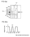
- Fig. 6(a) , Fig. 7(a) , Fig. 8(a) and Fig. 9(a) are enlarged views of a region enclosed by a single-dot chain line in Fig. 5 .
- Fig. 6(a) , Fig. 7(a) , Fig. 8(a) and Fig. 9(a) show respective states in which the detection position 142 moves relative to the irradiated section 115b when the ink cartridge 110 having a different remaining amount of ink 99 is mounted in the accommodating case 30 along an arrow 144.
- FIG. 9(a) correspond to the remaining amounts of ink 99 in Fig. 3(a) through Fig. 3(d) .
- solid lines indicate the ink cartridge 110 in the mounted attitude
- broken lines indicate the ink cartridge 110 immediately before the ink cartridge 110 takes the mounted attitude.
- Fig. 6(b) , Fig. 7(b) , Fig. 8(b) , and Fig. 9(b) are graphs that represent changes in the intensity of light received by the light receiving element 31b when the detection position 142 moves relative to the irradiated section 115b as shown in Fig. 6(a) , Fig. 7(a) , Fig. 8(a) , and Fig. 9(a) , respectively.
- the intensity of light received by the light receiving element 31b changes as shown in Fig. 6(b) .
- the intensity of light is A1 (t5).
- the detection position 142 reaches the left side wall 114e of the ink cartridge 110 (the left-side side wall section of the convex section 114d)
- the path of light is blocked by the left side wall 114e.
- the intensity of light is A0 (t6).
- the detection position 142 when the detection position 142 has finished moving past the left side wall 114e, the path of light is formed in a space between the left side wall 114e and the irradiated section 115b, and thus the intensity of light is A1 (t7).
- the detection position 142 moves past the light blocking section 162b and the slit 161 sequentially. Accordingly, the intensity of light once changes to A0 (t8), and thereafter becomes A1 (t9).
- the detection position 142 moves past the slit 161 and reaches the light blocking section 162a, the intensity of light becomes A0 (t10).
- the light blocking section 162a is at the detection position 142. The intensity of light therefore becomes A0 at t10 and thereafter.
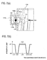
- the intensity of light received by the light receiving element 31b changes as shown in Fig. 7(b) .
- the intensity of light is A1 (t11).
- the detection position 142 reaches the left side wall 114e of the ink cartridge 110, the path of light is blocked by the casing 114.
- the intensity of light is A0 (t12).
- the detection position 142 when the detection position 142 has finished moving past the left side wall 114e, the path of light is formed in a space between the left side wall 114e and the irradiated section 115b, and thus the intensity of light is A1 (t13).
- the detection position 142 reaches the irradiated section 115b, the detection position 142 moves past the light blocking section 162b and relatively moves to the slit 161. Accordingly, the intensity of light once changes to A0 (t14), and thereafter becomes A1 (t15).
- the slit 161 is at the detection position 142, and therefore the intensity of light is A1 at t15 and thereafter.
- the intensity of light received by the light receiving element 31b changes as shown in Fig. 8(b) .
- the intensity of light is A1 (t16).
- the detection position 142 reaches the left side wall 114e of the ink cartridge 110, the path of light is blocked by the left side wall 114e.
- the intensity of light is A0 (t17).
- the detection position 142 when the detection position 142 has finished moving past the left side wall 114e, the path of light is formed in a space between the left side wall 114e and the irradiated section 115b, and thus the intensity of light is A1 (t18). Then, when the detection position 142 reaches the light blocking section 162b, the intensity of light becomes A0 (t19).
- the light blocking section 162b is located at the detection position 142. Accordingly, the intensity of light is A0 at t19 and thereafter.
- the intensity of light received by the light receiving element 31b changes as shown in Fig. 9(b) .
- the intensity of light is A1 (t20).
- the detection position 142 reaches the left side wall 114e of the ink cartridge 110, the path of light is blocked by the left side wall 114e.
- the intensity of light is A0 (t21).
- the detection position 142 when the detection position 142 has finished moving past the left side wall 114e, the path of light is formed in a space between the left side wall 114e and the irradiated section 115b, and thus the intensity of light is A1 (t22).
- the detection position 142 in the mounted attitude shown by the solid lines in Fig. 9(a) , the detection position 142 is located between the irradiated section 115b and the left side wall 114e. Accordingly, the intensity of light is A0 at t21 and thereafter.
- the intensity of light received by the light receiving element 31b shows different changes in patterns depending on the amount of ink 99 left in the mounted ink cartridge 110, as shown in Fig. 6(b) , Fig. 7(b) , Fig. 8(b) and Fig. 9(b) .
- the control section 22 acquires the remaining amount of ink 99 within the ink cartridge 110 when the ink cartridge 110 is mounted in the accommodating case 30, based on signals from the light receiving element 31b.
- the control section 22 includes a memory for storing data indicative of the patterns of change of the light intensity such as those shown in Fig. 6(b) , Fig. 7(b) , Fig. 8(b) and Fig. 9(b) , in association with the remaining amounts of ink 99 corresponding to the respective patterns of change.
- the control section 22 determines which of the changing patterns stored in the memory corresponds to the changes in the light intensity indicated by the signal from the light receiving element 31b, and acquires the remaining amount of ink 99 from the determined results.
- Table 1 shows the number of times the intensity of light received by the light receiving element 31b becomes A0 and the number of times the intensity of light received by the light receiving element 31b becomes A1 in respective cases. Note that, respective time to be A0 or A1 is shown in parentheses.
- the number of times the intensity of light received by the light receiving element 31b becomes A1 corresponds to a number which is obtained by adding 1, i.e., the path of light is once formed in the space between the irradiated section 115b and the left side wall 114e, to the number of times the irradiated light moves past the slit 161.
- the number of times the intensity of light received by the light receiving element 31b becomes A0 corresponds to the number of times the irradiated light from the light emitting element 31a is blocked by the light blocking sections 162a and 162b.
- the control section 22 stores data showing the Table 1 in the memory. Meanwhile, the control section 22 acquires the number of times the intensity of light received by the light receiving element 31b becomes A0 or A1, based on the signals from the light receiving element 31b. The control section 22 can detect which case among Fig. 6(b) through Fig. 9(b) corresponds to the residual amount of ink in the mounted link cartridge 110 by comparing the acquired number of times with the data stored in the memory. Then, the control section 22 informs the user of the detected remaining amount of ink 99 via the notifying section 29. For example, depending on respective patterns of change shown in Fig. 6(b) through Fig. 9(b) , a message may be shown on the display.
- the message may be such that the amount of ink 99 left in the mounted ink cartridge 110 is still sufficient, a replacement cartridge is necessary to be prepared since a smaller amount of ink 99 is left, the remaining amount of ink 99 will soon be empty, or the remaining amount mount of ink 99 is nearly empty, depending on the residual amounts of ink 99.
- the remaining amount of ink 99 can be known in at least four stages while the ink cartridge 110 is being mounted, as shown in Fig. 6 .
- the remaining amount of ink 99 can be grasped in more than four stages.
- a distance by which the irradiated section 115b and the casing 114 are separated is different depending on the remaining amounts of ink 99.
- lengths of a time period 171 and a time period 172 during which the intensity of light remains A1 are different from each other. Based on this difference, the remaining amount of ink 99 can be grasped in more than or equal to five stages in total, by determining that the remaining amount of ink 99 is smaller as the time period 172 is longer.
- the above description explains a case in which the remaining amount of ink 99 is acquired when the ink cartridge 110 is being mounted.
- the number of times the intensity of light received by the light receiving element 31b becomes A0 or A1 is identical to the respective cases when the ink cartridge 110 is being mounted.
- the remaining amount of ink 99 can also be grasped when the ink cartridge 110 is dismounted from the accommodating case 30.
- the irradiated section 115b is disposed at a position substantially vertically above the pivot shaft 117a when the ink 99 is sufficiently accommodated in the ink accommodating chamber 114c (refer to Fig. 2 ). Accordingly, the ink 99 reaches the float member 116 and the arm section 115a starts to pivotally move, the irradiated section 115b moves substantially rightward in Fig. 2 . The irradiated section 115b continues to be located generally above the pivot shaft 117a until the ink 99 comes almost empty (refer to Fig. 9(a) ).
- the irradiated section 115b moves, with respect to the mounting direction of the ink cartridge 110, from forward (leading side; leftward in Fig. 2 ) to rearward (trailing side; rightward in Fig. 2 ), in accordance with the decrease in the ink 99. That is, positions of the slit 161, the light blocking section 162a and the light blocking section 162b can reliably change in response to the remaining amounts of ink with respect to the mounting direction. In this way, the number of times intensity of light received by the light receiving element 31b becomes A0 or A1 can reliably change in accordance with the residual amounts of ink, thereby facilitating detection of the remaining amounts of ink.
- the slit 161 and the light blocking sections 162a and 162b are arranged alternately with respect to the mounting direction in the irradiated section 115b. Because the irradiated section 115b moves substantially in the mounting direction, the alternating arrangement of the slit 161 and the light blocking sections 162a and 162b can be maintained in the mounting direction regardless of the residual amounts of ink 99. Hence, the slit 161 and the light blocking sections 162a and 162b can be reliably dislocated with respect to the mounting direction in accordance with the decrease in the ink 99, and therefore the number of times the intensity of light received by the light receiving element 31b becomes A01 or A1 can reliably change in response to the remaining amounts of ink.
- the slit 161 is formed in the irradiated section 115b so as to extend along the up-down direction thereof. Therefore, the slit 161 can reliably deform relative to the detection position 142 in the mounting direction.
- Fig. 10 is a view showing a configuration of an ink cartridge 210 according to the second embodiment and the accommodation case 30.
- the ink cartridge 210 includes a detection member 215 and a float member 116 each constituting a remaining amount detecting mechanism.
- the detection member 215 includes an arm section 215a and an irradiated section 215b.
- the arm section 215a is a plate-shaped member that is bent twice approximately at a right angle, just like the arm section 115a.
- the irradiated section 215b is fixed to one end of the arm section 215a, whereas the float member 116 is fixed to the other end.
- a pivot shaft 117a is fixed to lower one of the bent corner sections of the arm section 215a.
- the position at which the pivot shaft 117a is supported by the ink cartridge 210 is adjusted such that the float member 116 fixed to the other end of the arm section 215a comes to a position near the bottom surface within an ink accommodating chamber 214c.
- the irradiated section 215b includes a slit-formed section 215c in which fine slits are formed.
- the slit-formed section 215c is arranged at the left end of the irradiated section 215b in Fig. 10 , and has a band-like zone spanning from the upper end to the lower end of the irradiated section 215b.
- a protruding section 215d is formed at the lower end of the irradiated section 215b.
- the protruding section 215d contacts a casing 214 of the ink cartridge 210, thereby restricting the movement of the irradiated section 215b so that the irradiated section 215b does not move lower than a position shown in Fig. 10 .
- the irradiated section 215b is held at a prescribed position from a state where the ink 99 is accommodated within the ink cartridge 210 to the maximum amount to a state where the liquid surface of ink 99 reaches the float member 116.
- the float member 116 When the liquid surface of ink 99 moves down to reach the float member 116, the float member 116 follows the liquid surface of ink 99 and moves in a direction L1. In conjunction with this, the irradiated section 215b also moves in a direction L2. Note that, as described above, the float member 116 is arranged a position near the bottom surface of the ink accommodating chamber 214c. Accordingly, if the liquid surface of ink 99 moves down to reach the float member 116, the remaining amount of ink 99 within the ink accommodating chamber 214c becomes small.
- Fig. 11 is an enlarged view of an area enclosed by a single-dot chain line in Fig. 10 , and shows how the irradiated section 215b changes its positions when the ink cartridge 210 is continued to be used in the mounted attitude.
- Fig. 11(a) shows a state before the liquid surface of ink 99 reaches the float member 116.
- Fig. 11(b) shows a state after the liquid surface of ink 99 has moved down to reach the float member 116, and the irradiated section 215b has moved slightly from the position of Fig. 10 in the direction L2.
- a reference number 242 indicates a range onto which light from the light emitting element 31a provided in the printer 20 is irradiated.
- a plurality of slits 261 is formed in the slit-formed section 215c.
- the slit 261 penetrates the irradiated section 215b in the thickness direction, and has a circular shape in a cross-section perpendicular to the thickness direction.
- the slits 261 are arranged in a lattice shape so that the slits 261 can be distributed evenly in the zone from the upper end to the lower end of the left half of the irradiated section 215b in Fig. 11 .
- Light irradiated on the slit-formed section 215c moves past the irradiated section 215b via the slits 261.
- These slits 261 are formed such that the diameters of the slits 261 are smaller than the diameter of the irradiation range 242 of light, and that the distances between the slits 261 are smaller than the diameter of the irradiation range 242 on average.
- the position of the irradiation range 242 relative to the irradiated section 215b changes in response to the amounts of ink 99 within the ink cartridge 210, as described below.
- the irradiation range 242 is located in a region other than the slit-formed section 215c in the irradiated section 215b.
- the irradiation range 242 is located within the region of the slit-formed section 215c.
- the irradiation range 242 is located outside the region of the irradiated section 215b.
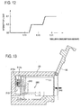
- Fig. 12 shows changes in the intensity of light received by the light receiving element 31b as the irradiation range of light changes from Fig. 11(a) to Fig. 11(c) .
- the horizontal axis of Fig. 12 represents time (and the consumption amount of ink 99), whereas the vertical axis represents the intensity of light.
- Time t29-t31 correspond to time when the irradiated section 215b is in the respective states of Fig. 11(a) through Fig. 11(c) .
- the irradiation range 242 when the irradiation range 242 is located in the region other than the slit-formed section 215c in the irradiated section 215c, light is blocked by the irradiated section 215b and thus the light received by the light receiving element 31b is A0.
- the intensity of light received by the light receiving element 31b is A1.
- the irradiation range 242 when the irradiation range 242 is located within the range of the slit-formed section 215c, light moves past the irradiated section 215b via at least one of the slits 261.
- the irradiation range 242 includes a region where the slits 261 are not opened. Accordingly, part of light irradiated on the irradiation range 242 is blocked by the region where the slits 261 are not opened. Hence, intensity A2 of light received by the light receiving element 31b at t30 is greater than A0 at t29 and is smaller than A1 at t31.
- the intensity of light received by the light receiving element 31b changes twice as the remaining amount of ink 99 becomes small.
- the remaining amount of ink 99 can be grasped in three stages by counting how many times the intensity of light has changed by the present time.
- the remaining amount of ink 99 can be grasped in three stages by determining current intensity of light to be any one of A0-A2, without counting the number of changes in the intensity of light.
- the second embodiment shows a configuration that enables the remaining amount of ink 99 within the ink cartridge 210 to be detected not only when the ink cartridge 210 has been in the mounted attitude from the beginning of use until present, but also when the ink cartridge 210 is mounted in or dismounted from the accommodating case 30.
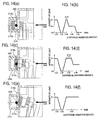
- Fig. 13 shows a state where the ink cartridge 210 is being mounted in or dismounted from the accommodating case 30.
- Broken lines represent the ink cartridge 210 in a state where the ink cartridge 210 is slid slightly to the right from the mounted attitude.
- the ink cartridge 210 moves between the position indicated by the broken lines and the position in the mounted attitude.
- the irradiation range 242 moves relative to the irradiated section 215b, such that the irradiation range 242 cuts the irradiated section 215b in a direction parallel to a direction 243, for example.
- Fig. 14(a), Fig. 14(c), and Fig. 14(e) are enlarged views of a region enclosed by a single-dot chain line in Fig. 13 .
- Fig. 14(a), Fig. 14(c), and Fig. 14(e) show respective states where the irradiation range 242 moves relative to the irradiated section 215b when the ink cartridges 210 having a different residual amount of ink 99 are mounted in the accommodating case 30 along a direction of an arrow 244.
- the remaining amounts of ink 99 in Fig. 14(a), Fig. 14(c), and Fig. 14(e) correspond to the remaining amounts of ink 99 in Fig. 11(a) through Fig. 11(c) .
- Fig. 14(a), Fig. 14(c), and Fig. 14(e) correspond to the remaining amounts of ink 99 in Fig. 11(a) through Fig. 11(c) .
- Fig. 14(a), Fig. 14(c), and Fig. 14(e) solid lines show the ink cartridge 210 in the mounted attitude, while broken lines show the ink cartridge 210 immediately before the ink cartridge 210 takes the mounted attitude.
- Fig. 14(b), Fig. 14(d), and Fig. 14(f) are graphs that represent changes in the intensity of light received by the light receiving element 31b, when the irradiation range 242 moves relative to the irradiated section 215b as shown in Fig. 14(a), Fig. 14(c), and Fig. 14(e) , respectively.
- the intensity of light received by the light receiving element 31b changes as shown in Fig. 14(b) .
- the intensity of light is A1 (t32).
- the irradiation range 242 reaches the left side wall of the casing 214 of the ink cartridge 210, the light path is blocked by the casing 214.
- the intensity of light is A0 (t33).
- the irradiation range 242 finishes moving past the left side wall, the light path is formed in a space between the left side wall and the irradiated section 215b, and thus the intensity of light becomes A1 (t34).
- the irradiation range 242 is located at the slit-formed section 215c of the irradiated section 215b, the intensity of light becomes A2 (t35).
- the intensity of light becomes A0 (t36).
- the intensity of light received by the light receiving element 31b changes as shown in Fig. 14(d) .
- the intensity of light is A1 (t37).
- the irradiation range 242 reaches the left side wall of the casing 214 of the ink cartridge 210, the light path is blocked by the casing 214.
- the intensity of light is A0 (t38).
- the irradiation range 242 is located at the slit-formed section 215c of the irradiated section 215b, the intensity of light becomes A2 (t40).
- the intensity of light is A2 at t40 and thereafter.
- the intensity of light received by the light receiving element 31b changes as shown in Fig. 14(f) .
- the intensity of light is A1 (t41).
- the irradiation range 242 reaches the left side wall of the casing 214 of the ink cartridge 210, the light path is blocked by the left side wall.
- the intensity of light is A0 (t42).
- the intensity of light becomes A1 (t43).
- the intensity of light is A1 at t43 and thereafter.
- the control section 22 acquires the remaining amount of ink 99 within the ink cartridge 210 based on signals from the light receiving element 31b, when the ink cartridge 210 is being mounted in the accommodating case 30.
- the control section 22 stores data indicating Table 2 in the memory. Meanwhile, the control section 22 acquires respective numbers of times the intensity of light received by the light receiving element 31b become A0-A2, based on the signals from the light receiving element 31b. The control section 22 can detect which case among Fig. 14(b), Fig. 14(d) and Fig. 14(f) corresponds to the residual amount of ink in the mounted link cartridge 210 by comparing the acquired numbers of times with the data stored in the memory. Then, the control section 22 informs the user of the detected remaining amount of ink 99 via the notifying section 29. For example, when the remaining amount of ink 99 is smaller than a predetermined value, the control section 22 may warn the user that the remaining amount of ink 99 is small via the notifying section 29.
- remaining amounts of ink 99 becomes A0 at t36, A2 at 40, and A1 at t43, respectively, i.e., different from each other in the state where the ink cartridge 210 is inserted in the accommodating case 30 to take the mounted attitude. Accordingly, the remaining amounts of ink may be detected based only on whether the intensity of light received by the light receiving element 31b is any one of A0-A1 when the ink cartridge 210 is mounted in the accommodating case 30 and takes the mounted attitude.
- the remaining amount of ink 99 can be detected in at least three stages at the time of mounting the ink cartridge 210, as shown in Fig. 14 .
- the remaining amount of ink 99 can be grasped in more than or equal to four stages.
- the separation distance between the irradiated section 215b and the casing 214 is different depending on the remaining amount of ink 99.
- the lengths of a time period 271 and a time period 272 during which the intensity of light is A1 are different from each other.
- the remaining amount of ink 99 can be grasped in more than or equal to four stages in total, by determining that the remaining amount of ink 99 becomes smaller as the time period 272 is longer. Moreover, as in the first embodiment, residual amounts of ink 99 can also be detected when the ink cartridge 210 is dismounted from the accommodating case 30.
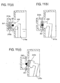
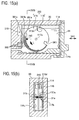
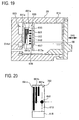
- Fig. 15(a) is a view showing a configuration of an ink cartridge 310 according to the third embodiment and the accommodation case 30.
- Fig. 15(b) is a cross-sectional view taken along a line XVB-XVB in Fig. 15(a) .
- the ink cartridge 310 is provided with a remaining-amount detecting mechanism.
- the remaining-amount detecting mechanism includes a remaining-amount detecting member 350.
- the remaining-amount detecting member 350 is integrally formed of a disk-shaped detection member 315 and the float member 116.
- the float member 116 is fixed to a position close to the periphery of the detection member 315.
- the detection member 315 is a disk-shaped plate member.
- the detection member has a diameter slightly smaller than the height of the ink accommodating chamber 114c.
- the detection member is disposed at a position center of the ink accommodating chamber 114c with respect to the left-right direction in Fig. 15(b) .
- a rod-shaped reverse-rotation preventing member 315d is provided at the ceiling of the ink accommodating chamber 114c.
- the reverse-rotation preventing member 315 contacts the float member 116 and restricts the movement of the float member 116.
- the pivot shaft 117a is fixed at the center of the disk-shaped detection member 315.
- the pivot shaft 117a is fixed at the center of the disk-shaped detection member 315.
- the pivot shaft 117a is supported by a bearing 117b fixed to the casing 114 so that the detection member 315 can pivotally move (can rotate).
- the detection member 315 is restricted from rotating in a reverse direction but is able to rotate in a circumferential direction L.
- the detection member 315 is about to rotate.
- the detection member 315 rotates in the direction L.
- the reverse-rotation preventing member 315d need not be necessarily provided. Similar operations are made possible if the float member 116 is arranged at a position moved in the normal rotational direction from a position directly above in Fig. 15(a) (the twelve o'clock position in a clock) when the remaining amount of ink 99 is close to the maximum amount. However, providing the reverse-rotation preventing member 315d can more reliably present the detection member 315 from rotating in the reverse direction, even in disturbances such as vibrations.
- the light emitting element 31a and the light receiving element 31b are disposed respectively at a position substantially center of the accommodating case 30 in the up-down direction, and leftward in the casing 114 in Fig. 15(a) .
- the pivot shaft 117a is supported by the bearing 117b so that a detection position 342 onto which light from the light emitting element 31a is irradiated comes to a prescribed position. In this way, the detection position 342 is brought into a position close to the center of the detection member 315 with respect to the up-down direction, vicinity of the left end of the detection member 315, and the same as that of the pivot shaft 117a in vertical direction.
- the detection member 350 has a slit 361.
- the slit 361 is formed at a position rotated clockwise from the position of the float member by approximately 90 degrees in a circumferential direction.
- the slit 361 cut the detection member 315 in a direction from the periphery to the center thereof at a length longer than the minimum distance from the periphery to the detection position 342 (refer to Fig. 16(c) ).
- the detection member 315 is formed with slits 391a-391c extending along the circumferential direction.
- the slits 391a-391c are formed in the vicinity of the circumference of the detection member 315. Of these, the slit 391c is closest to the circumference of the detection member 315, whereas the slit 391a is farthest from the circumference of the detection member 315. Of both ends of the slits 391a through 391c, each of the one ends farthest from the slit 361 is arranged at a position the same with each other with respect to the circumferential direction.
- the slits 391a-391c extend counterclockwise and along the circumferential direction in which each of the other ends is arranged at a position separated from the respective one ends.
- the other end of the slit 391a is farthest from the slit 361 in the circumferential direction, whereas the other end of the slit 391b is secondly farthest from the slit 361.
- the other end of the slit 391c is closest to the slit 361.
- the other end of the slit 391c may be separated from the slit 361 or adjacent to the slit 361.
- Light blocking sections 362 are formed between each of the slits 361, and also in a region around the slit 361 for blocking the light irradiated from the light emitting element 31a.
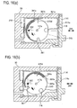
- Fig. 15(a) and Figs. 16(a) through 16(c) respectively show an internal configuration of the ink cartridge 110 in the mounted attitude.
- the amounts of ink 99 accommodated in the ink accommodating chamber 114c are different from each other.
- Fig. 15(a) shows a state where the ink 99 is nearly fully accommodated in the ink accommodating chamber 114c.
- the detection position 342 is located at a position vicinity of the ends of the slits 391a-391c far from the slit 361.
- the float member 116 is made of a resin material of which specific gravity is smaller than ink, or is formed with a cavity inside if the float member 116 is made of a material whose specific gravity is greater than ink. Thus, as a whole, the float member 116 has smaller specific gravity than ink 99.
- the float member 116 since the float member 116 is larger than the detection member 315 with respect to a direction of the pivot shaft 117a, the float member 116 can occupy a relatively large volume so that buoyancy can be ensured readily.
- the detection member 315 rotates in the direction L.
- the slits 391a-391c move past the detection position 342. If these slits 391a-391c (first sections) are located at the detection position 342 when moving past the detection position 342, since light emitted from the light emitting element 31a passes through these slits, the intensity of light received by the light receiving element 31b is A1. If the light blocking sections 362 (second sections) are located at the detection position 342, since the light from the light emitting element 31a is blocked, the intensity of light received by the light receiving element 31b is A0.
- how many slits have moved past the detection position 342 can be detected from combinations of the numbers of times the intensity of light received by the light receiving element 31b becomes A0 and A1 respectively.
- the detected number of slits is three.
- the light blocking sections 362 block the irradiated light four times.
- Fig. 16(a) shows a state where the ink 99 has decreased to a certain amount from the state of Fig. 15(a) .
- the detection position 342 is located at a position between the end of the slit 391a closer to the slit 361 and the end of the slit 391b closer to the slit 361 with respect to the circumferential direction of the detection member 315.
- the slits 391b and 391c have moved past the detection position 342. Therefore, two slits are detected. Meanwhile, the number of times the light blocking sections 362 have blocked the irradiated light is three.
- Fig. 16 (b) shows a state where the ink 99 has further decreased to a certain amount from the state of Fig. 16(a) .
- the detection position 342 is located at a position between the end of the slit 391b closer to the slit 361 and the end of the slit 391c closer to the slit 361 with respect to the circumferential direction of the detection member 315.
- the slit 391c moves past the detection position 342.
- detected number of slits is one, while the number of times the light blocking sections 362 block the irradiated light is two.
- Fig. 16(c) shows a state where the ink 99 has further decreased from the state of Fig. 16(b) , and becomes almost empty in the ink accommodating chamber 114c.
- the detection position is located within a region where the slit 361 (third portion) is formed.
- the slit-formed area is located on the path along which the detection position 342 moves.
- the detection member 315 never blocks the detection position 342. That is, no slit is detected.
- the control section 22 acquires numbers of slits from signals from the light receiving element 31b, and notifies the user of information on the residual amounts of ink in accordance with the acquired numbers via the notifying section 29. For example, depending on the numbers of slits being 3, 2, 1 or 0, a message may be shown on the display.
- the message may be such that the amount of ink 99 left in the mounted ink cartridge 110 is still sufficient, a replacement cartridge is necessary to be prepared since a smaller amount of ink 99 is left, the remaining amount of ink 99 will soon be empty, or the remaining amount mount of ink 99 is nearly empty, depending on the residual amounts of ink 99.
- the remaining amounts of ink 99 may be detected based on the numbers of times the light blocking sections 362 block the irradiated light.
- the residual amounts of ink 99 within an ink cartridge can be acquired not only while the ink cartridge is being used (in a case where the ink cartridge has been in the mounted attitude since the beginning of use), but also when the ink cartridge is being mounted in and dismounted from an accommodating case.
- Fig. 17 shows a remaining-amount detecting member 450 according to the fourth embodiment.
- the remaining-amount detecting member 350 of the third embodiment is replaced by a remaining-amount detecting member 450.
- the remaining-amount detecting member 450 includes a detection member 415 and the float member 116.
- the detection member 415 has a substantially disk shape.
- the float member 116 is fixed to a position vicinity of the circumference of the disk of the detection member 415.
- the detection member 415 is formed with a plurality of slits 461. These slits 461 are arranged at an equal interval in the circumferential direction of the detection member 415.
- the slit 461a is formed at a position rotated clockwise from the position of the float member 116 by approximately 90 degrees in the circumferential direction.
- the slit 461b cuts the detection member 415 in a direction from the periphery to the center thereof at a length longer than the minimum distance from the periphery to a detection position 442.
- the widths of the slits 461a in the circumferential direction are identical to one another.
- each slit 461a has a length identical to each other and extends from the vicinity of the circumference toward the center of the detection member 415.
- Light blocking sections 462 are formed between each of the slits 461a and the slit 461b.
- the detection member 1215 is formed with slits 491a through 491c extending along the circumferential direction.
- Each of the slits 491a through 491c is formed in a region between the slits 461a and the circumference of the detection member 415.
- the slit 491a is closest to the circumference of the detection member 415, whereas the slit 491c is farthest from the circumference of the detection member 415.
- Each of one ends of the slits 491a through 491c is arranged at a position slightly closer to the float member 116 than the slit 461a farthest from the slit 461b in the circumferential direction.
- the other ends of the slits 491a through 491c are arranged at positions different from one another.
- the other end of the slit 491a is farthest from the slit 461b in the circumferential direction, whereas the other end of the slit 491c is closest to the slit 461b.
- the remaining-amount detecting member 450 rotates in a direction M in accordance with decrease of ink, when the ink cartridge is mounted in the accommodating case and starts to be used.
- the slits 461a consecutively move past the detection position 442. That is, at the detection position 442, the slits 461a and the light blocking sections 462 are alternately detected.
- the control section 22 counts how many slits 461a and the light blocking sections 462 have moved past the detection position 442 since when the ink cartridge is mounted, in accordance with the signals from the light receiving element 31b. And, based on the counted numbers, the control section 22 acquires the residual amounts of ink 99 at present.
- the remaining-amount detecting member 450 can also acquire the remaining amounts of ink 99 when the ink cartridge is being mounted in and dismounted from the accommodating case, as described below.
- Fig. 17 shows the detection position 442 when the remaining amount of ink 99 is close to the maximum amount.
- the detection position 442 moves relative to the remaining-amount detecting member 450 along a single-dot chain line 481a, in a direction of an arrow 444a. Accordingly, by the time the ink cartridge has been mounted, the slits 491a through 491c move past the detection position 442. That is, when the remaining amount of ink 99 is close to the maximum amount, the optical sensor section 31 detects that all of the slits 491a through 491c have moved past the detection position 442.
- the remaining-amount detecting member 450 rotates within the ink cartridge in a direction M. Assume that the remaining amount of ink 99 has decreased to m1 which is smaller than the maximum amount. At the same time, suppose that the remaining-amount detecting member 450 has rotated along the direction M from the position shown in Fig. 17 by an angle formed between a single-dot chain line 481b and the single-dot chain line 481a. In such a state, when the ink cartridge is mounted in the accommodating case, the detection position 442 relatively moves in a direction of an arrow 444b along the single-dot chain line 481b.
- the slits 491a and 491b move past the detection position 442. That is, when the remaining amount of ink 99 is m1 (not shown), the optical sensor section 31 detects that two of the slits 491a through 491c have moved past the detection position 442.
- the residual amounts of ink 99 can be detected in three stages by detecting how many slits of the slits 491a through 491c have moved past the detection position 442 via the optical sensor section 31.
- the remaining amounts of ink 99 may also be detected based only on the numbers of times the light blocking sections 462 block the light irradiated from the light emitting element 31a.
- the residual amounts of ink 99 may also be detected by combinations of the number of times the light blocking sections 462 block the light from the light emitting element 31a and the number of slits that moved past the detection position 442.
- a fifth embodiment as in the fourth embodiment, remaining amounts of ink 99 in an ink cartridge can be acquired both while the ink cartridge is used and when the ink cartridge is being mounted in and dismounted from the accommodating case.
- descriptions for configurations the same as those in the fourth embodiment are omitted.
- Aldo for configurations the same as those in the fourth embodiment, the same reference numerals are provided.
- Fig. 18(a) and Fig. 18(b) show a remaining-amount detecting member 550 according to the fifth embodiment.
- the remaining-amount detecting member 550 includes a detection member 515 and the float member 116.
- the detection member 515 is formed with a plurality of slits 561a and a slit 561b.
- the remaining-amount detecting member 550 corresponds to the remaining-amount detecting member 450 of the fourth embodiment in which the slits 561a are formed instead of the slits 461a and the slits 491a through 491c.
- Light blocking sections 562 are formed between each of the slits 561a.
- One ends of the slits 561a are arranged on the circumference of the detection member 515.
- the slits 561a are formed such that each slit 561a extends linearly from one end thereof in a direction away from the circumference of the detection member 515.
- the other ends of the slits 561a are arranged inside a circle 582 and in a region adjacent to the circle 582.
- the circle 582 is concentric with the detection member 515 and smaller than the detection member 515.
- the slits 561a are formed such that acute angles formed between each slit 561a and the radial direction of the detection member 515 become larger as the slit 561a is closer to the slit 561b.
- the slit s1 is farthest from the slit 561b, whereas the slit s3 is closest to the slit 561b.
- the acute angle ⁇ 1 of the slit s1 farthest from the slit 561b is the smallest, whereas the acute angle ⁇ 3 of the slit s3 closest to the slit 561b is the largest.
- the slits 561a are formed such that the number of the slits 561a intersected by the above-described imaginary line at a region outside the circumference of the circle 582 changes depending on rotational angles from the imaginary line 581a.
- the reason why the number of the slits 561a located only at the outer circumferential region is counted is that, this is the region that moves past a detection position 542 when the ink cartridge is being mounted or dismounted
- the number of the slits 561a intersected by the imaginary line 581a at the outer circumferential region of the circle 582 is one.
- the number of the slits 561a intersected by an imaginary line 581b at the outer circumferential region of the circle 582 is two, the imaginary line 581b being obtained by rotating the imaginary line 581a by an angle ⁇ 1.
- the number of the slits 561a intersected by an imaginary line 581c at the outer circumferential region of the circle 582 is three, the imaginary line 581c being obtained by rotating the imaginary line 581a by an angle ⁇ 2 (> ⁇ 1).
- the number of the slits 561a intersected by a certain imaginary line at the outer circumferential region of the circle 582 is greater than or equal to the number of the slits 561a intersected by any other imaginary line at the outer circumferential region of the circle 582, the any other imaginary line being obtained by rotating the imaginary line 581a by an angle smaller than the rotational angle of the certain imaginary line from the imaginary line 581a. That is, the slits 561a are formed such that the number of the slits 561a intersected by an imaginary line at the outer circumferential region of the circle 582 increases in a stepwise manner, as the rotational angle from the imaginary line 581a increases.
- the number of the slits 561a intersected by an imaginary line is two or more
- the number of the slits 561a intersected by the imaginary line at the outer circumferential region of the circle 582 can be configured to increase in a stepwise manner in the remaining-amount detecting member 550 of Fig. 18 , in consideration of the positional relationship between each slit 561a and each imaginary line together with the number of the intersected slits.
- the remaining amount of ink 99 can be obtained by the remaining-amount detecting member 550 when the ink cartridge is being mounted in the accommodating case.
- Fig. 18 shows the detection position 542 in a case where the remaining amount of ink 99 is close to the maximum amount.
- the detection position 542 moves relative to the detection member 515 in a direction of an arrow 544a along the imaginary line 581a.
- the detection position 542 moves relative to the remaining-amount detecting member 550 from a detection position 542a to the detection position 542.
- the number of the slits 561a detected by the optical sensor section 31 (corresponding to the slit s1) is one.
- the remaining-amount detecting member 550 is in a position rotated in the direction N.
- the detection position 542 moves along one of imaginary lines X which is rotated about the center of the detection member 515 from the imaginary line 581a.
- the detection position 542 moves in a direction of an arrow 544b along the imaginary line 581b.
- the number of slits 561a detected by the optical sensor section 31 at the detection position 542 is equal to the number of the slits 561a intersected by the imaginary line X at the region outside of the circumference of the circle 582.
- the slits 561a are formed so as to satisfy the above-described Condition 1 and Condition 2.
- the remaining-amount detecting member 550 is moved to a position rotated by a larger angle from the state of Fig. 18 . That is, the remaining amount of ink 99 is determined to be smaller, as the number of slits 561a detected by the optical sensor section 31 at the detection position 542 is larger
- the optical sensor section 31 detects two slits 561a.
- the detection position 542 moves along the imaginary line 581c
- the detection position 542 moves relative to the remaining-amount detecting member 550 from a detection position 542d to a detection position 542e.
- the optical sensor section 31 detects three slits 561a. Accordingly, the remaining amount of ink 99 is determined to be smaller in the latter case than in the former case.
- the detection position 542 moves relative to the detection member 515 along the circle 582 in a direction opposite to the direction N. Accordingly, the slits 561a and the light blocking sections 562 are detected alternately at the detection position 542.
- the remaining-amount detecting member 550 can also detect the remaining amount of ink 99 in multiple stages, during use of the ink cartridge.
- residual amounts of ink 99 may also be grasped based only on who many times the light blocking sections 562 block the light from the light emitting element 31a.
- remaining amounts of ink 99 may be detected by combinations of the number of times the light blocking sections 562 block the light from the light emitting element 31a and the number of slits that moved past the detection position 542.
- Fig. 19 is a cross-sectional view showing a configuration of an ink cartridge 610 according to a sixth embodiment and the accommodating case 30.
- descriptions for configurations the same as those in the first embodiment are omitted. Aldo, for configurations the same as those in the first embodiment, the same reference numerals are provided.
- a remaining-amount detecting member 650 integrally includes a detection member 615 and a float member 616.
- the float member 616 has an approximately rectangular parallelepiped shape, and has a mass per unit volume that is smaller than the density of ink 99.
- the detection member 615 is a plate-shaped member of which thickness direction is parallel to a direction extending from the near side toward the far side of Fig. 19 .
- the float member 616 is fixed to the lower end of the detection member 615.
- a plurality of slits 661 is formed in the detection member 615, the plurality of slits 661 being arranged in the up-down direction of Fig. 19 .
- Each of the slits 661 has an identical shape and an identical size to each other.
- the slits 661 are arranged at an equal interval in the up-down direction.
- Light blocking sections 662 are formed between the slits 661.
- the detection member 615 is formed with slits 691a-691c extending in the up-down direction. Each upper end of the slits 691a-691c is arranged at a position the same as each other in the up-down direction near the upper end of the detection member 615. Of the slits 691a-691c, the slit 691c is the longest in the up-down direction, the slit 691b has the second longest length, and the slit 691a is the shortest.
- the lower end of the slit 691c is closest to the float member 616
- the lower end of the slit 691b is the second closest to the float member 616
- the lower end of the slit 691a is the farthest from the float member 616.
- a restricting member 617 is integrally fixed to a casing 614 of the ink cartridge 610.
- the restricting member 617 is a plate-shaped member extending downward perpendicularly from the ceiling surface within the casing 614.
- the restricting member 617 is formed with a restricting surface 617a which is in parallel with the up-down direction.
- left-side inner wall surface 614d of the casing 614 extends in parallel with the restricting surface 617a, and is in confrontation with the restricting surface 617a in the left-right direction in Fig. 19 .
- the restricting member 617 is arranged such that the separation distance between the inner wall surface 614d and the restricting surface 617a is slightly larger than the maximum width of the remaining-amount detecting member 650 in the left-right direction. Further, the remaining-amount detecting member 650 is arranged between the inner wall surface 614d and the restricting surface 617a. The restricting surface 617a and the inner wall surface 614d restrict the movement of the remaining-amount detecting member 650 in the left-right direction, and the remaining-amount detecting member 650 can move with respect to the up-down direction (restricting mechanism).
- the float member 616 moves down in accordance with the downward movement of the ink surface.
- the entirety of the remaining-amount detecting member 650 moves down. Because the remaining-amount detecting member 650 is restricted from the movement in the left-right direction of Fig. 19 by the inner wall surface 614d and the restricting surface 617a, the light blocking sections 662 do not move away from a detection position 642 in the left-right direction. With the downward movement of the remaining-amount detecting member 650, a state where the light blocking section 662 is located at the detection position 642 and a state where the slit 661 is located at the detection position 642 are repeated alternately.
- control section 22 can grasp in multiple stages how much amount of ink 99 is left at present, by counting how many times the state where the intensity of light is A1 and the state where the intensity of light is A0 have appeared by the present time.
- a path along which the detection position 642 cuts across the remaining-amount detecting member 650 becomes different depending on residual amounts of ink 99. For example, when the ink 99 is nearly at the maximum amount, the upper end of the remaining-amount detecting member 650 is contact with the ceiling surface within the casing 614. At this time, the detection position 642 cuts across a region between the lower end of the slit 691c and the lower end of the slit 691b. Then, when the ink 99 has decreased by a certain amount, the remaining-amount detecting member 650 starts to move down from the ceiling surface within the casing 614. Next, as shown in Fig.
- the detection position 642 comes to a position passing between the lower end of the slit 691b and the lower end of the slit 691a.
- the detection position 642 is located at a position passing between each upper end of the slits 691a-691c and the lower end of the slit 691a.
- the remaining-amount detecting member 650 is so configured that how many slits out of the slits 691a-691c the detection position 642 moves past can change in response to the remaining amounts of ink 99. Accordingly, when the ink cartridge 610 is mounted in the accommodating case 30, detecting residual amounts of ink within the mounted ink cartridge 610 becomes possible by counting the number of slits that moves past the detection position 642 based on signals from the light receiving element 31b.
- the remaining amounts of ink 99 may also be detected based only on the numbers of times the light blocking sections 662 block the light irradiated from the light emitting element 31a.
- the residual amounts of ink 99 may also be detected by combinations of the number of times the light blocking sections 662 block the light from the light emitting element 31a and the number of slits that moved past the detection position 642.
- the present embodiment may also be used for detecting residual amounts of ink 99 within the ink cartridge 610 while the ink cartridge is in use, in addition to the case where the ink cartridge is being mounted in or dismounted from the accommodating case.
- the remaining-amount detecting member 650 is formed with both the slits 661 and the slits 691a-691c.
- only the slits 691a-691c may be formed therein. In this case, residual amounts of ink 99 can be detected only when the ink cartridge is being mounted or dismounted.
- a liquid cartridge and a recording system according to the present invention are not limited to the above-described embodiments, and various modifications and improvements can be made therein without departing from the scope of the claims.
- the above-described embodiments employ such a configuration that a detection member and a float member are fixed integrally.
- these need not be fixed integrally if the detection member is configured to be able to move in conjunction with the movement of the float member.
- the float member and the detection member are separate members, and the float member is in contact with the detection member. The float member moves to push the detection member in response to the movement of the float member as the ink 99 decreases, thereby making the detection member move along the predetermined path.
- Fig. 21 shows an embodiment with such a configuration.
- Fig. 21(a) shows a remaining-amount detecting member 1050 including a detection member 1015 and the float member 116.
- the slits 461a, 461b, and 491a-491c of the detection member 415 in the fourth embodiment are replaced by light reflecting sections 1061a, 1061b and 1091a-1091c that reflect light. That is, the light reflecting sections 1061a, 1061b, and 1091a-1091c correspond to the slits 461a, 461b and 491a-491c, respectively. Further, light blocking sections 1062 are formed between the light reflecting sections 1061a and 1061b, and between each of the light blocking sections 1091a-1091c.
- Fig. 21(b) and Fig. 21(c) show an ink cartridge 1010 having the remaining-amount detecting member 1050 shown in Fig. 21(a) and the accommodating case 30.
- a light emitting element 1031a and a light receiving element 1031b are provided in the accommodating case 30.
- the angles formed between the light emitting element 1031a and the light receiving element 1031b are adjusted so that light from the light emitting element 1031a is reflected by the surface of the detection member 1015, and that the reflected light is received by the light receiving element 1031b.
- the light reflecting sections 1061a, 1061b and 1091a-1091c has a function to direct light from the light emitting element 1031a toward the light receiving element 1031a, just as the slits 461a, 461b and 491a-491c (first section).
- intensity of light received by the light receiving element 1031b when any of the light reflecting sections 1061a, 1061b, and 1091a-1091c is located at a detection position at which light from the light emitting element 1031a arrives is greater than intensity of light received by the light receiving element 1031b when the light blocking section 1062 is located at the detection position.
- an ink cartridge capable of detecting residual amounts of ink 99 therein based on the intensity of light received by the light receiving element 1031b can be realized as in the above-described embodiments.
- a region other than the light reflecting sections 1061a, 1061b and 1091a-1091c may be made of a material having light transmissive characteristics.
- the detection member 1015 has a function that prevents the reflected light from reaching the light receiving element 1031b, which is similar to the function of the light blocking sections 1062.
- the irradiated section is disposed at a position substantially above the pivot shaft 117a.
- the positional relationship between the irradiated section and the pivot shaft 117a may be different from that in the embodiments described above.
- an irradiated section 1115b is arranged at a position leftward of the pivot shaft 117a.
- the irradiated section 1115b moves along a direction O, that is, substantially upward.
- a slit 1161 is preferably formed obliquely with respect to the up-down direction.
- the slit 1161 may be preferably formed in such a shape that a detection position 1142 can cut across the slit 1161 so as to move relative to the same. In this way, if slits are formed in an appropriate shape, numbers of slits detected at the detection position 1142 and patterns of change in the intensity of light can reliably change when the ink cartridge 1110 is being mounted or dismounted in a direction 1144. Hence, even in the case where the irradiated section 1115b is disposed at a position leftward of the pivot shaft 117a, the ink cartridge 1110 allows residual amounts of ink to be detected at the time of detachment.
- the above-described embodiments include configurations where the detection member is formed with slits.
- These slits may be made of any material and have any shape, as long as the slits are configured to transmit light readily compared with the light blocking section.
- a transparent resin material may be filled in through-holes penetrating the detection member, or slits may have a shape other than a rectangular shape or circular shape.
- the light blocking section need not block light completely, and may be made of a material that does not transmit light readily, compared with the light transmission section such as slits.
- slits or through-holes that transmit light are formed in the detection member made of a material having light blocking characteristics.
- a seal material having light blocking characteristics may be affixed to the detection member made of material having light transmissive characteristics, with shapes and at positions the same as the slits or the like in the above-described embodiments.
- the light transmission section having a function similar to that in the above-described embodiments can be formed in a simple manner, and thus the remaining-amount detecting member can be manufactured easily.
- the remaining-amount detecting member 550 is configured such that the number of the slits 561a detected at the detection position 542 increases as ink decreases when the ink cartridge is mounted or dismounted. More specifically, as ink decreases, the number of detected slits 561a changes like (1) one ⁇ (2) two ⁇ (3) three. However, the remaining-amount detecting member may be configured such that the number of the detected slits 561a temporarily decreases as ink decreases.
- the remaining-amount detecting member 550 may be configured such that the number of the detected slits 561a changes like (1) one ⁇ (2) zero ⁇ (3) one ⁇ (4) two ⁇ (5) one ⁇ (6) two ⁇ (7) three, as ink decreases. In this case as well, if the number of the detected slits 561a is zero, for example, the remaining amount of ink is determined to be at least greater than the state of (3) or later. If the number of the detected slits 561a is three, the remaining amount of ink is known to be small.
- irradiated section in each embodiment corresponds to a portion of a detection member at which slits and light blocking sections are formed, unless explicitly described such as the irradiated section 115b in the first embodiment.
Abstract

Description
- The present invention relates to a liquid cartridge, more particularly to a liquid cartridge mountable in a recording device for supplying liquid thereto, and also relates to a recording system including the liquid cartridge.
- In a conventional recoding device that ejects recording liquid such as an inkjet recording device, a separate liquid cartridge is often used for supplying liquid to the recoding device. If there is a small amount of liquid left in the liquid cartridge when a user replaces the liquid cartridge, the liquid in the liquid cartridge will soon become empty if a large amount of printing is performed right after the replacement. In such a case, the user needs to replace the liquid cartridge again in the middle of the printing operation. In order to avid such a situation, there is a need for a configuration that detects whether the amount of liquid remaining in the liquid cartridge is small, and, if so, warns that the cartridge needs to be replaced soon.
- For example,
patent document 1 discloses that a float is provided in a liquid cartridge so as to be dislocated in accordance with a decrease in the amount of liquid in the liquid cartridge. A degree of displacement of the float in a horizontal direction can be detected by a reflective optical sensor that moves horizontally relative to the liquid cartridge. This construction can detect how much liquid is left in the liquid cartridge as needed. Or alternatively, a plurality of optical sensors can be employed with respect to the horizontal direction, instead of moving an optical sensor, in order to detect residual amounts of liquid as inpatent document 1. With these methods, detecting amounts of liquid left in a liquid cartridge right after the liquid cartridge is mounted may determine whether the remaining amount of liquid in the liquid cartridge is little. - [Patent Document 1] Japanese Patent Application Publication No.
2004-34406 Fig. 2 ) - However, if an optical sensor is configured to move relative to a liquid cartridge as disclosed in
patent document 1, dimensions of a recoding device tend to be large. Moreover, providing a plurality of optical sensors leads to an increase in the number of parts. Hence, a liquid cartridge employing the above-described detecting methods necessitates an increase in costs of a recoding device. - It is an object of the present invention to provide a liquid cartridge and recoding system capable of detecting a residual amount of liquid when the liquid cartridge is being mounted without increasing costs of the recording system.
- A liquid cartridge according to the present invention is mountable in a recording device provided with a mount section in which the liquid cartridge is mounted through an insertion opening from a predetermined mounting direction and light detecting means including a light emitting section that emits light to a direction orthogonal to the mounting direction and a light receiving section that receives the emitted light from the light emitting section. The liquid cartridge includes a liquid accommodating chamber that accommodates liquid, an outlet that introduces liquid to outside, and a remaining-amount detecting mechanism provided within the liquid accommodating chamber for detecting remaining amounts of liquid. The remaining-amount detecting mechanism includes a float that follows liquid surface of the liquid accommodated in the liquid accommodating chamber and is dislocated in accordance with decrease in the liquid, and an irradiated section that is dislocated along a predetermined path in conjunction with displacement of the float, the irradiated section including a first section and a second section, the first section directing the emitted light toward the light receiving section, the second section blocking the emitted light, the first section and the second section being arranged alternately. The irradiated section is configured such that at least one of the number of times the first section intersects with the emitted light and the number of times the second section intersects with the emitted light can change depending on where the irradiated section is located along the predetermined path, from when the liquid cartridge is inserted through the insertion opening until when the liquid cartridge has mounted in the mount section.
- Further, a recoding system according to the present invention includes a liquid cartridge and a recording device in which the liquid cartridge is mounted, the recording system ejecting liquid supplied from the liquid cartridge onto an ejection medium so that the liquid adheres to the ejection medium. The recording device includes a mount section in which the liquid cartridge is mounted from a predetermined mounting direction through an insertion opening, and light detecting means that includes a light emitting section that emits light to a direction orthogonal to the mounting direction and a light receiving section that receives the emitted light from the light emitting section, the light detecting means being disposed at a position where the light emitting section and the light receiving section can interpose a portion of the liquid cartridge mounted in the mount section. The liquid cartridge includes a liquid accommodating chamber that accommodates liquid, an outlet that introduces the liquid to outside, and a remaining-amount detecting mechanism provided within the liquid accommodating chamber for detecting residual amounts of liquid. The remaining-amount detecting mechanism includes a float that follows liquid surface of the liquid accommodated in the liquid accommodating chamber and is dislocated in accordance with decrease in the liquid, and an irradiated section that is dislocated along a predetermined path in conjunction with displacement of the float, the irradiated section including a first section and a second section, the first section directing the emitted light toward the light receiving section, the second section blocking the emitted light, the first section and the second section being arranged alternately. The irradiated section is configured such that at least one of the number of times the first section intersects with the irradiated light and the number of times the second section intersects with the irradiated light can change depending on where the irradiated section is located along the predetermined path, from when the liquid cartridge is inserted through the insertion opening until when the liquid cartridge has mounted in the mount section.
- According to the liquid cartridge and the recording system of the present invention, the remaining-amount detecting mechanism is dislocated along a predetermined path in conjunction with displacement of the float in accordance with decrease in the liquid. And the irradiated section is configured such that at least one of the number of times the first section intersects with the emitted light and the number of times the second section intersects with the emitted light can change depending on where the irradiated section is located along the predetermined path. Accordingly, at which position on the predetermined path the irradiated section is located can be detected by detecting the irradiated light at the light receiving section and counting the number of times either the first section or the second section intersects with the light. That is, amounts of liquid left in the liquid cartridge are acquired.
- In the present invention, the remaining-amount detecting mechanism is preferably provided with an arm section that connects the float and the irradiated section, and a pivoting mechanism that pivotably movably supports the arm section. With this configuration, since the arm section connects the irradiated section and a pivot point of the pivot mechanism, the remaining-amount detecting mechanism can be made compact, compared with a case in which the remaining-amount detecting mechanism is formed of a disk-shaped member. Also, the distance between the irradiated section and the pivot point can be made longer by simply making the length of the arm longer, thereby enabling the remaining-amount detecting mechanism to be still retained compact.
- Further in the present invention, preferably the remaining-amount detecting mechanism further includes a restricting mechanism that restricts movements of the float and the irradiated section to the prescribed path, and the restricting mechanism restricts pivotal movement of the arm section along a direction in which the float tries to move up because of the liquid accommodated in the liquid accommodating chamber. With this construction, the arm is configured not to pivotally move when a sufficient amount of liquid is left, but to start making a pivotal movement when the liquid has decreased to a certain amount. Hence, accurate detection of the residual amounts of liquid becomes possible in a circumstance where remaining amounts of liquid is necessary to be detected, i.e., when the liquid has decreased.
- In the present invention, further, preferably the irradiated section is dislocated from a leading side to a trailing side in the mounting direction as the irradiated section moves along the predetermined path in accordance with the decrease in liquid accommodated in the liquid accommodating chamber. With this construction, at least one of the number of times the first section intersects with the irradiated light and the number of times the second section intersects with the irradiated light can reliably change in response to the residual amounts of liquid, when the irradiated section is dislocated from the leading side to the trailing side in the mounting direction. Hence, residual amounts of liquid can be reliably detected. The remaining-amount detecting mechanism can also be configured such that changes in the remaining amount of liquid after the liquid cartridge has been mounted can be detected by positional changes of the irradiated section. In this case, single remaining-amount detecting mechanism allows detecting both the residual amounts of liquid when mounted and the changes in the amounts of liquid thereafter.
- Further in the present invention, preferably the predetermined mounting direction is a horizontal direction, and the irradiated section is always located at a position above the pivot point of the pivot mechanism while the irradiated section moves along the predetermined path. With this construction, the irradiated section can be dislocated from the leading side to the trailing side at a large scale in the predetermined path, thereby allowing the residual mounts of liquid to be detected more reliably.
- Or, in the present invention, the irradiated section preferably includes at least one first section and at least two second sections, and the first and second sections are preferably arranged on a straight line drawn by the emitted light irradiating the irradiated section, regardless of where the first and the second sections are located along the predetermined path. With this construction, the first section and the second section can be arranged on the straight line along which the light irradiates, i.e., the straight line along the mounting direction, regardless of the residual amounts of liquid in the liquid accommodating chamber. On the other hand, as described above, the irradiated section is configured to be dislocated in the mounting direction as the liquid decreases. Accordingly, at least either the number of times the first section intersects or the number of times the second section intersects can change reliably in accordance with decrease of the liquid, when the liquid cartridge is being mounted.
- Further, in the present invention, the remaining-amount detecting mechanism may include a remaining-amount detecting member and a pivot mechanism that pivotably movably supports the remaining-amount detecting member, the remaining-amount detecting member integrally including the float and the irradiated section. The first section and the second section may be arranged along a circumference of the pivot mechanism having the pivot point as a center, and may also be arranged alternately in a radial direction passing through the pivot center, the first section extending longer or shorter as the first section is located closer to the pivot center. With this construction, when the liquid cartridge is mounted, an irradiation position of the emitted light can be made movable relative to the remaining-amount detecting member in the radial direction thereof. In this case, the light reliably intersects with the first section and the second section. The first section extends along the circumference having the pivot center as its center, and length of the first section with respect to the extending direction is arranged to be longer or shorter, according to the distance from the pivot point. On the other hand, the remaining-amount detecting member pivotally moves in the circumferential direction in response to the decrease of liquid. Hence, at least either the number of times the first section intersects or the number of times the second section intersects can change reliably in accordance with decrease of the liquid.
- Further, in the present invention, each of one ends of the first sections is preferably located at a position the same as each other with respect to the circumferential direction of the pivot mechanism having the pivot point as a center, and first sections preferably extend from the one ends along a direction identical to each other with respect to the circumferential direction. With this structure, each of one ends of the first sections is located at the same position with respect to the circumferential direction, and each of the first sections extends in the same direction. Moreover, as described above, the first sections are formed so as to become longer or shorter in accordance with the distance from the pivot point. Accordingly, in this liquid cartridge, as the liquid decreases, the number of times the first sections intersect with the light can be made fewer or greater.
- Further, in the present invention, the remaining-amount detecting member is preferably formed in a disk shape having the pivot point of the pivot mechanism as a center. If the remaining-amount detecting member has a shape other than a disk, such as a rectangular shape for example, the remaining-amount detecting member necessarily has a planar end surface. If the end surface moves past the liquid surface when the remaining-amount detecting member pivotally moves, air bubbles may adhere to the end surface. Adherence of air bubbles to the end surface prevents the remaining-amount detecting member from moving smoothly, thereby leading to unstable detection of the residual amount of the liquid. In contrast, if the remaining-amount detecting member has a disk shape, no planar end surface is formed as in the rectangular shaped remaining-amount detecting member. Hence, air bubbles do not easily adhere when the remaining-amount detecting member pivotally moves, thereby leading to stable detection of the residual amount of liquid.
- Further in the present invention, preferably the irradiated section is further formed with a third section that directs the emitted light toward the light receiving section, and the third section is located at a position separated from or adjacent to, and rearward of the first section extending the longest with respect to a moving direction of the remaining-amount detecting member in response to the decrease in the liquid within the liquid accommodating chamber, and extends from an peripheral end of the remaining-amount detecting member to a position at which the emitted light is irradiated. With this structure, the third section is formed at a position rearward of the first section with respect to the moving direction of the remaining-amount detecting member in response to the decrease in the liquid, i.e., at a position at which the light is irradiated when the liquid has decreased to a minimum amount. On the other hand, the third section extends from the peripheral end of the remaining-amount detecting member to a position at which the emitted light is irradiated. Hence, this liquid cartridge can be configured such that the light never irradiates the second section if the liquid has decreased to the minimum amount when the liquid cartridge is mounted, thereby realizing easy detection of the state in where the smallest amount of liquid is left in the liquid cartridge.
- Alternatively, in the present invention, the remaining-amount detecting mechanism may be provided with a remaining-amount detecting member that integrally includes the float and the irradiated section, and a pivot mechanism that pivotably movably supports the remaining-amount detecting member. The first section and the second section may be arranged alternately in the circumferential direction of the pivot mechanism having the pivot point as a center, and the first section may have an elongated shape extending in a direction, the direction having a larger or smaller angle relative to a straight line passing through the pivot point, as the first section moves in the circumferential direction. With this structure, when the liquid cartridge is mounted, the irradiation position of the light is configured to be movable relative to the remaining-amount detecting member in the radial direction thereof. On the other hand, the first section is configured to have a larger or smaller angle relative to the straight line passing through the pivot point, as the first section moves in the circumferential direction. Therefore, each of the first sections can be aligned with each other with respect to the radial direction in the remaining-amount detecting member. Hence, how many times the light intersects with the first sections at the time of mounting can change reliably as the liquid decreases.
- In the present invention, each of one ends of the first sections is preferably located at a position separated from the pivot point by a distance identical to each other, and other ends of the first sections are preferably arranged such that the number of times the first sections intersect with the emitted light increases or decreases in accordance with the decrease of the liquid within the liquid accommodating chamber from when the liquid cartridge is inserted through the insertion opening until when the liquid cartridge has mounted in the mount section. With this structure, the liquid cartridge reliably allows to detect that smaller amounts of liquid is left as the number of times the light intersects with the first section is fewer or greater.
- In the present invention, preferably the irradiated section has a plurality of first sections, and the plurality of the first sections is formed in the irradiated section so as to intersect with a circumference of a circle passing through a point at which the emitted light is irradiated and having the pivot point as a center when the liquid cartridge is mounted in the recording device. With this configuration, when the liquid cartridge is mounted in the recording device, the irradiation position of light is configured to move along the circumference about the pivot point in accordance with the decrease of the liquid. In other words, the light intersects with the plurality of the first sections as the liquid decreases. Hence, current residual amount of liquid can be obtained by counting how many first sections have intersected with the light by present.
- In the present invention, the remaining-amount detecting mechanism may further include a restricting mechanism that restricts the movement of the float and the irradiated section to move linearly along a moving direction, the moving direction intersecting with the mounting direction and the direction of the emitted light, and the first section may extend along the moving direction, and the first section and the second section may be arranged in the mounting direction. With this arrangement, residual amounts of liquid can also be detected at the time of mounting the liquid cartridge even if the irradiated section moves linearly as the liquid decreases.
- Further, in the present embodiment, a plurality of the first sections having a length different from each other is preferably arranged in the mounting direction. With this structure, since each of the first sections has a different length with respect to the moving direction of the irradiated section, the number of the first sections with which the light intersects can reliably change when the liquid cartridge is mounted along the mounting direction. Hence, residual amounts of liquid can also be detected at the time of mounting the liquid cartridge even if the irradiated section moves linearly as the liquid decreases.
-
- [
Fig. 1 ] A schematic view showing a configuration of a printer system according to a first embodiment of the present invention; - [
Fig. 2 ] Cross-sectional views showing a detailed configuration around an ink cartridge mounted in a printer shown inFig.1 , wherein (a) is a cross-sectional view taken along a line IIA-IIA inFig. 1 , and (b) is a cross-sectional view taken along a line IIB-IIB in (a); - [
Fig. 3 ] Partial enlarged views showing positions of a remaining-amount detecting member in response to amounts of ink remaining in an ink cartridge according to the first embodiment, wherein (a) shows a position of the remaining-amount detecting member when the remaining amount of ink is nearly at a maximum amount, (b) shows a position of the remaining-amount detecting member when the remaining amount of ink becomes less than the maximum amount, (c) shows a position of the remaining-amount detecting member when the remaining amount of ink becomes even smaller, and (e) shows a position of the remaining-amount detecting member when the ink cartridge becomes almost empty; - [
Fig. 4 ] A graph showing intensity of light that an optical sensor section detects in accordance with a decrease in the amount of ink in the ink cartridge according to the first embodiment; - [
Fig. 5 ] A cross-sectional view showing a state in which the ink cartridge according to the first embodiment is being mounted in or dismounted from the printer; - [
Fig. 6 ] (a) is a partial enlarged view ofFig. 5 showing a state where the ink cartridge according to the first embodiment is being mounted in or dismounted from the printer when substantial amount of ink remains in the ink cartridge, and (b) is a graph showing intensity of light that a light receiving element receives in the state of (a); - [
Fig. 7 ] (a) is a partial enlarged view ofFig. 5 showing a state where the ink cartridge according to the first embodiment is being mounted in or dismounted from the printer when smaller amount of ink remains in the ink cartridge, and (b) is a graph showing intensity of light that the light receiving element receives in the state of (a); - [
Fig. 8 ] (a) is a partial enlarged view ofFig. 5 showing a state where the ink cartridge according to the first embodiment is being mounted in or dismounted from the printer when even smaller amount of ink is left in the ink cartridge, (b) is a graph showing intensity of light that the light receiving element receives in the state of (a); - [
Fig. 9 ] (a) is a partial enlarged view ofFig. 5 showing a state where the ink cartridge according to the first embodiment is being mounted in or dismounted from the printer when almost no ink remains in the ink cartridge, and (b) is a graph showing intensity of light that the light receiving element receives in the state of (a); - [
Fig. 10 ] A cross-sectional view showing a detailed configuration around an ink cartridge according to a second embodiment; - [
Fig. 11 ] Partial enlarged views ofFig. 10 showing positions of a remaining-amount detecting member in response to amounts of ink remaining in the ink cartridge according to the second embodiment, wherein (a) shows a position of the remaining-amount detecting member when the remaining amount of ink is nearly at a maximum amount, (b) shows a position of the remaining-amount detecting member when the remaining amount of ink becomes less than the maximum amount, and (c) shows a position of the remaining-amount detecting member when the remaining amount of ink becomes even smaller; - [
Fig. 12 ] A graph showing intensity of light that an optical sensor section detects in accordance with a decrease in the amount of ink in the ink cartridge according to the second embodiment; - [
Fig. 13 ] A cross-sectional view showing a state in which the ink cartridge according to the second embodiment is being mounted in or dismounted from a printer; - [
Fig. 14 ] Partial enlarged views ofFig. 10 showing states where the ink cartridge according to the second embodiment is being mounted in or dismounted from the printer in response to amounts of ink remaining in the ink cartridge and corresponding graphs showing intensity of light, wherein (a) is a view illustrating a position of the remaining-amount detecting member when the remaining amount of ink is nearly at a maximum amount, (b) is a graph showing intensity of light that an optical sensor of (a) detects, (c) is a view illustrating a position of the remaining-amount detecting member when the remaining amount of ink becomes less than the state shown in (a), (d) is a graph showing intensity of light that the optical sensor of (c) detects, (e) is a view illustrating a position of the remaining-amount detecting member when the remaining amount of ink becomes even smaller, and (f) is a graph showing intensity of light that the optical sensor of (e) detects; - [
Fig. 15 ] (a) is a cross-sectional view showing a configuration of an ink cartridge according to a third embodiment and its surroundings, and (b) is a cross-sectional view taken along a line XVB-XVB in (a); - [
Fig. 16(a) ] A cross-sectional view showing the configuration of the ink cartridge and its surroundings when the amount of ink becomes smaller than the state ofFig. 15 ; - [
Fig. 16(b) ] A cross-sectional view showing the configuration of the ink cartridge and its surroundings when the amount of ink becomes even less than the state ofFig. 16(a) ; - [
Fig. 16(c) ] A cross-sectional view showing the configuration of the ink cartridge and its surroundings when the amount of ink becomes even smaller than the state ofFig. 16(b) ; - [
Fig. 17 ] An elevation view of a remaining-amount detecting member in an ink cartridge according to a fourth embodiment; - [
Fig. 18 ] An elevation view of a remaining-amount detecting member in an ink cartridge according to a fifth embodiment; - [
Fig. 19 ] A cross-sectional view showing a configuration of an ink cartridge according to a sixth embodiment and its surroundings; - [
Fig. 20 ] A variation of a remaining-amount detecting member according to the sixth embodiment; - [
Fig. 21 ] Schematic views showing a configuration of an ink cartridge according to a variation of the first to sixth embodiments and its surroundings, wherein (a) is an elevation view of a remaining-amount detecting member, (b) is a cross-sectional view showing light emitted from a light emitting element, and (c) is a cross-sectional view showing how light is reflected in the remaining-amount detecting member; and - [
Fig. 22 ] A cross-sectional view showing a configuration of an ink cartridge according to a variation of the first and second embodiments and its surroundings. -
- 1 printer system
- 10, 110, 210, ..., 610, 1010, 1110 ink cartridge
- 20 inkjet printer
- 22 control section
- 23 inkjet head
- 23a nozzle
- 24 conveying unit
- 25 ink tube
- 29 notifying section
- 30 accommodating case
- 31 optical sensor section
- 31a, 1031a light emitting element
- 31b, 1031b light receiving element
- 99 ink
- 114 cartridge casing
- 114c, 214c ink accommodating chamber
- 115, 215, ..., 615, 1015 detection member
- 115a, 215a, arm section
- 115b, 215b, 1115b irradiated section
- 116, 616 float member
- 117a pivot shaft
- 142, 242, ..., 642, 1142 detection position
- 161, 262, ..., 661, 1161 slit
- 391a, 391b, 391c, slit
- 491a, a491b, 491c slit
- 691a, 691b, 691c slit
- 162a, 162b, 462, 562, 662 light blocking section
- 215c the slit-formed section
- 350, 450, 550, 650, 750, 1050 remaining-amount detecting member
- 617 restricting member
- 1061a light reflecting section
- 1062 light blocking section
- Following is an explanation about a
printer system 1 according to preferred embodiments of the present invention. In the following description, unless otherwise stated, "upper" and "lower" are used to define that each represents upper and lower respectively in a vertical direction in a state where an ink cartridge of the present invention is mounted on a printer. -
Fig. 1 is a view showing a schematic configuration of aprinter system 1. Theprinter system 1 includes an ink cartridge 10 and aninkjet printer 20. The 20 (hereinafter referred to as "printer 20") includes acontrol section 22, a notifyingsection 29, aninkjet head 23, a conveyingunit 24, and anaccommodating case 30. Thecontrol section 22 controls operations of theprinter 20. The notifyingsection 29 notifies a user of theprinter 20 of various information on operation status of theprinter 20, in accordance with instructions of thecontrol section 22. For example, the notifyingsection 29 may include a display so that various information can be displayed on the display to notify the user of the information. - The
inkjet head 23 has a plurality ofnozzles 23a. An ink channel (not shown) is formed inside theinkjet head 23. Ink supplied from the ink channel is ejected downward from thenozzles 23a. The conveyingunit 24 conveys printing paper P to a position below theinkjet head 23. The ink ejected from theinkjet head 23 falls onto the printing paper P conveyed by the conveyingunit 24. Thecontrol section 22 controls ink ejection from theinkjet head 23 and conveyance of the printing paper P by the conveyingunit 24, based on image data transmitted from a personal computer or the like connected to theprinter 20. Thus, theprinter 20 forms an image corresponding to the image data on the printing paper P. - The
accommodating case 30 is a case that accommodates theink cartridge 110. An accommodating space 32 (mount section) having substantially a rectangular parallelepiped shape is formed within theaccommodating case 30. Theink cartridge 110 is mounted in and dismounted from theaccommodating space 32 along a direction shown by an arrowB. Concave sections 34 are formed on an inner surface of theaccommodating case 30 that defines theaccommodating space 32. Theconcave sections 34 extend from an opening of theaccommodating space 32 to the far side of theaccommodating space 32 along the direction B. - Further, the
accommodating case 30 includes anoptical sensor section 31, anink inlet port 33, and alid section 35. Theoptical sensor section 31 is provided such that theoptical sensor section 31 is exposed to theaccommodating space 32 within theaccommodating case 30. Theink inlet port 33 is an opening connecting to anink outlet port 112 of theink cartridge 110 so that ink flowing out of theink outlet port 112 can flow into theink inlet port 33, when theink cartridge 110 is mounted in theaccommodating case 30. Theink inlet port 33 is in communication with the ink channel within theinkjet head 23 via anink tube 25. Thus, the ink from theink cartridge 110 is introduced to the ink channel inside theinkjet head 23. Thelid section 35 opens and closes the opening serving as an entrance/exit of theaccommodating case 30, and is provided to theaccommodating case 30 so as to be capable of swinging in a direction of an arrow A. Thelid section 35 opens the opening of theaccommodating case 30 when theink cartridge 110 is mounted in or dismounted from theaccommodating case 30, and closes the opening of theaccommodating case 30 once theink cartridge 110 is mounted. - The
ink cartridge 110 has substantially a rectangular parallelepiped shape that is approximately the same as theaccommodating space 32, and is slightly smaller than theaccommodating space 32.Convex sections 113 are formed on a side surface of theink cartridge 110. Theconvex sections 113 have shapes that are substantially the same as theconcave sections 34 formed in theaccommodating case 30, and have sizes that can fit in theconcave sections 34. Further, theink cartridge 110 has anink outlet port 112. When theink cartridge 110 is being mounted in or dismounted from theaccommodating case 30, theink cartridge 110 is slid along the direction of the arrow B while theconvex sections 113 of theink cartridge 110 and theconcave sections 34 of theaccommodating case 30 are coupled to each other. That is, theconvex sections 113 and theconcave sections 34 are guide members that cause theink cartridge 110 to move along the detachable direction B. When theink cartridge 110 is mounted in theaccommodating case 30, theink outlet port 112 is in communication with theink inlet port 33. -
Figs. 2(a) and 2(b) are views showing an internal configuration of theink cartridge 110 and a configuration of theaccommodating case 30. InFigs. 2(a) and 2(b) , theink cartridge 110 takes a mount attitude in which theink cartridge 110 is mounted in theaccommodating case 30. Note that, in this specification, the attitude of the ink cartridge when mounted in the accommodating case as shown inFig. 2 is referred to as "mounted attitude".Fig. 2(b) is a cross-sectional view taken along a line IIB-IIB inFig. 2(a) . - The
ink cartridge 110 has a cartridge casing 114 (hereinafter referred to as "casing 114"). Thecasing 114 is made of a material having light transmissive characteristics, such as a translucent resin material. A hollowink accommodating chamber 114c is formed within thecasing 114, andink 99 is accommodated in theink accommodating chamber 114c. That is, thecasing 114 defines theink accommodating chamber 114c (liquid accommodating chamber) that accommodates ink. Thecasing 114 is formed in a cube shape as a whole. Thecasing 114 has aconvex portion 114d protruding leftward threrefrom inFig. 2(a) . The inner space of theconvex portion 114d constitutes a portion of theink accommodating chamber 114c. - The
ink accommodating chamber 114c is in communication with anink outlet section 39 that allows ink to flow to the outside via apassage 38. An open/close mechanism (not shown) that opens and closes theink outlet section 39 is provided within thepassage 38. This open/close mechanism normally closes theink outlet section 39, and opens theink outlet section 39 when theink outlet section 39 is connected to theink inlet port 33 of theaccommodating case 30. - A remaining-amount detecting mechanism is provided within the
ink accommodating chamber 114c for detecting residual amounts ofliquid 99. The remaining-amount detecting mechanism includes adetection member 115 and afloat member 116. The detection member 15 is a plate-shaped member made of a material having light blocking characteristics, and includes anarm section 115a and anirradiated section 115b. Thearm section 115a has twocorner sections arm section 115a is bent approximately perpendicularly. Theirradiated section 115b is fixed to an end of thearm section 115a, whereas thefloat member 116 is fixed to the other end. The float member 16 is made of a material of resin or the like, and so configured that its mass per unit volume is smaller than the density ofink 99. For example, thefloat member 116 may be made of a material of which specific gravity is smaller than ink, or may be formed as a hollow body having a cavity inside if thefloat member 116 is made of a material of which specific gravity is greater than ink. - The
irradiated section 115b has generally a square shape. A generally rectangular-shapedslit 161 is formed in theirradiated section 115b. Theslit 161 extends downward from an upper end of theirradiated section 115b to a position close to a lower end of theirradiated section 115b inFig. 2(a) . Further, theslit 161 is arranged at a position slightly leftward of the center of theirradiated section 115b with respect to the left-right direction ofFig. 2 . Further,light blocking sections slit 161 is interposed between thelight blocking sections irradiated section 115b, theslit 161 is a portion through which light from alight emitting element 31a transmits (a portion that directs incident light toward a light receiving element; first section), whereas thelight blocking sections light emitting element 31a. - The
arm section 115a is pivotably supported by a pivot mechanism. The pivot mechanism is configured of apivot shaft 117a and a bearing (not shown). Thepivot shaft 117a is fixed to one of the bent corner sections in thearm section 115a, i.e., thecorner section 115e. Thepivot shaft 117a is pviotably movably supported by the bearing. This configuration allows thearm section 115a to pivotally move about thepivot shaft 117a. In the present embodiment, thepivot shaft 117a is supported at a position close to the lower section of the left inner wall surface of theink accommodating chamber 114c. Further, the position at which thepivot shaft 117a is supported is adjusted such that thefloat member 116 is arranged near the bottom surface within theink accommodating chamber 114c in the up-down direction, and that theirradiated section 115b is arranged within the region of theconvex portion 114d in theink accommodating chamber 114c. - A protruding
section 115d is formed on the lower end of theirradiated section 115b. The protrudingsection 115d makes contact with theconvex section 114d, thereby restricting theirradiated section 115b from moving further below from the position shown inFig. 2 (restricting mechanism). Thus, when theink 99 is accommodated in theink cartridge 110 to the maximum amount, thearm section 115a is in a status where thecorner section 115f is disposed at a position vertically above thecorner section 115e. Thearm section 115a and theirradiated section 115b are also maintained at a prescribed position, from a state where a maximum amount ofink 99 is accommodated within theink cartridge 110 to a state where the liquid surface of theink 99 reaches thefloat member 116. Then, when the liquid surface ofink 99 lowers in a direction R and reaches thefloat member 116, thefloat member 116 follows the liquid surface ofink 99 and starts to pivotally move about thepivot shaft 117a in a direction Q1. In conjunction with this, theirradiated section 115b also moves in a direction Q2. Note that, as described above, thefloat member 116 is arranged at a position close to the bottom surface of theink accommodating chamber 114c. Accordingly, when the liquid surface ofink 99 moves down and reaches thefloat member 116, the remaining amount ofink 99 within theink accommodating chamber 114c is small. - Further, the
optical sensor section 31 includes alight emitting element 31a (light emitting section) and alight receiving element 31b (light receiving section). Thelight emitting element 31a and thelight receiving element 31b are arranged at a position identical to each other with respect to the up-down direction of the drawing. Thelight emitting element 31a is connected to thecontrol section 22 and emits light in accordance with instructions from thecontrol section 22. Thelight receiving element 31b is also connected to thecontrol section 22. When receiving light, thelight receiving element 31b transmits a signal indicative of an intensity of the received light to thecontrol section 22. As described above, thecasing 114 is formed of a material having light transmissive characteristics. Hence, as long as no blocking object exists on a path of the light within the ink accommodating chamber 14c, the light from thelight emitting element 31a reaches thelight receiving element 31b along the above-mentioned virtual straight line. However, if light enters in a direction orthogonal to a direction in which thickness of the side walls of thecasing 114 extends, the incident light needs to pass inside the side walls, not through theink accommodating chamber 114c, until the light arrives at thelight receiving element 31b. Hence, if the light enters in the direction orthogonal to the thickness direction of the side walls of thecasing 114, the intensity of light becomes fairly small, compared with a case where light enters in a direction parallel to the thickness direction. Note that, instead of making the entirety of the ink cartridge 10 of a material having light transmissive characteristics, windows may be formed in thecasing 114 so that light from thelight emitting element 31a can penetrate thecasing 114 through the windows along the virtual straight line. - As shown in
Fig. 2(b) , in the first embodiment, thelight emitting element 31a and the light, receivingelement 31b are arranged such that theconvex section 114d is interposed between the light emittingelement 31a and thelight receiving element 31b. Thus, light 141 emitted from thelight emitting element 31a can arrive at thelight receiving element 31b through theconvex section 114d. - Hence, as shown in
Fig. 2(a) , a position through which emitted light from thelight emitting element 31a passes is located within theconvex section 114d (hereinafter, this position is referred to as "detection position"). That is, thedetection position 142 is a position interposed between the light emittingelement 31a and thelight receiving element 31b when theink cartridge 110 is mounted in the accommodating case 130. - With the above-described configuration, the position of the
irradiation member 115b changes in response to amounts of ink remaining within theink accommodating chamber 114c. For example, when the remaining amount of ink is a certain amount, thelight blocking section 162a or thelight blocking section 162b is located in the ink accommodating chamber 14c. In contrast, when the remaining amount of ink is another amount, theslit 161 comes to the detection position. When either thelight blocking section 162a or thelight blocking section 162b is located at thedetection position 142, light from thelight emitting element 31a reaches thelight receiving element 31b. Accordingly, the intensity of light received by thelight receiving element 31b when theslit 161 is located at the detection position142 is greater than the intensity of light received by thelight receiving element 31b when the either one of thelight blocking sections - Hereinafter is an explanation on how the light received by the
light receiving element 31b changes in response to the residual amounts ofink 99. First, changes in the intensity of light are explained if theink cartridge 110 has been in use from when theink cartridge 110 was mounted until theink 99 becomes empty. Next, changes in the intensity of light when thelink cartridge 110 is being mounted or dismounted. - If the
ink cartridge 110 has been continuously used until theinternal ink 99 becomes empty from the time of being mounted, the intensity of light received by thelight receiving element 31b changes as follows in accordance with decrease of the ink within theink accommodating chamber 114c.Fig. 3 is an enlarged view of a region enclosed by a single-dot chain line ofFig. 2 .Fig. 3(a) shows a state before the liquid surface ofink 99 reaches thefloat member 116.Fig. 3(b) shows a state after the liquid surface ofink 99 has lowered and reached thefloat member 116, and theirradiated section 115b has moved a little in the direction Q2 ofFig. 3(a) from the position of Fig. 4(a).Fig. 3(c) shows a state after the liquid surface ofink 99 has lowered, and theirradiated section 115b has further moved from the position ofFig. 3(b). Fig. 3(d) shows a state after the liquid surface ofink 99 has lowered, and theirradiated section 115b has further moved from the position ofFig. 3(c) . - The state of the
irradiated section 115b changes depending on the amounts ofink 99 left within theink cartridge 110, as described below. InFig. 3(a) , theirradiated section 115b is in a state where thelight blocking section 162a is located at thedetection position 142. InFig. 3(b) , theirradiated section 115b is in a state where theslit 161 is located at thedetection position 142. InFig. 3(c) , theirradiated section 115b is in a state where thelight blocking section 162b is located at thedetection position 142. InFig. 3(d) , theirradiated section 115b is in a state where theirradiated section 115b has finished moving past thedetection position 142 and is located at a position rightward of thedetection position 142. In this way, theirradiated section 115b moves from the left to the right ofFig. 3 in response to the decrease in theink 99. -
Fig. 4 shows changes in the intensity of light received by thelight receiving element 31b when the irradiation range of light changes as shown in fromFig. 3(a) to Fig. 3(d) . The horizontal axis ofFig. 4 represents time (and the consumption amount of ink 99), whereas the vertical axis represents the intensity of light. A light intensity A1 indicates the intensity in a case where light from thelight emitting element 31a reaches thelight receiving element 31b without being blocked by thedetection member 115. A light intensity A0 indicates the intensity in a case where light from thelight emitting element 31a reaches thelight receiving element 31b when blocked by thedetection member 115. Time t1-t4 respectively correspond to time when theirradiated section 115b is in each state ofFigs. 3(a)-3(d) . - At t1, because light is blocked by the
light blocking section 162a, the intensity of light received by thelight receiving element 31b is A0. At t2, because light is received by thelight receiving element 31b through theslit 161, the intensity of light received by thelight receiving element 31b is A1. At t3, because light is blocked by thelight blocking section 162b, the intensity of light received by thelight receiving element 31b is A0. At t4 and thereafter, because theirradiated section 115b has finished moving past thedetection position 142, the intensity of light is A1. - As described above, according to the first embodiment, when the
ink 99 within theink accommodating chamber 114c decreases to a small amount, the liquid surface ofink 99 reaches thefloat member 116, and thefloat member 116 begins to move. As theink 99 further decreases, the position of thedetection member 115 sequentially changes in conjunction with thefloat member 116, from a first position where thelight blocking section 162a is located at thedetection position 142, to a second position where theslit 161 is located at thedetection position 142, then to a third position where thelight blocking section 162b is located at thedetection position 142, and finally to a fourth position where theirradiated section 115b has finished moving past thedetection position 142. Simultaneously, the status of light received by thelight receiving element 31b sequentially changes from a first state where the intensity is A0, to a second state where the intensity is A1, to a third state where the intensity is A0, and finally to a fourth state where the intensity is A1. - The
control section 22 acquires which of the first through fourth states the current status corresponds to, thereby identifying how much amount ofink 99 is left in four stages. Specifically, thecontrol section 22 counts how many times the status of light received by thelight receiving element 31b switches between the light intensity A0 and the light intensity A1. Then, depending on the switched number of times being 0-3 times, the present status is determined to be any one of the first through fourth states. Then, based on the determined result on the residual amount ofink 99, thecontrol section 22 notifies the user of information indicating the remaining amount ofink 99 via the notifyingsection 29. For example, in accordance with each of the first through fourth states, a message may be shown on the display, wherein the message may inform that the remaining amount ofink 99 is still sufficient, the remaining amount ofink 99 is small, the remaining amount ofink 99 is further small, or the remaining amount ofink 99 is nearly empty. - The
ink cartridge 110 has a configuration that allows the amount ofink 99 left in theink cartridge 110 to be detected, not only when theink cartridge 110 continues to be in the mounted attitude until present from when theink cartridge 110 was first used, but also when theink cartridge 110 is being mounted in or dismounted from theaccommodating case 30 during in use.Fig. 5 shows a state where theink cartridge 110 is being mounted in or dismounted from theaccommodating case 30. Broken lines represent a state of theink cartridge 110 slid slightly rightward from the mounted attitude. When theink cartridge 110 is being mounted in theaccommodating case 30, theink cartridge 110 moves to the mounted attitude via a position indicated by the broken lines. At this time, thedetection position 142 moves relative to theirradiated section 115b such that thedetection position 142 cuts across theirradiated section 115b along a direction parallel to adirection 143, for example. - Note that, the
casing 114 is made of a material having light transmissive characteristics, as described above. Therefore, light emitted from thelight emitting element 31a enters theink accommodating chamber 114c via thecasing 114. However, if aleft side wall 114e of thecasing 114 is located at thedetection position 142, incident light from thelight emitting element 31a enters in the direction perpendicular to the thickness direction of theleft side wall 114e (left-right direction ofFig. 5 ). Hence, the intensity of light received by thelight receiving element 31b becomes dramatically smaller if theleft side wall 114e is located at thedetection position 142, compared with states before and after this case. -
Fig. 6(a) ,Fig. 7(a) ,Fig. 8(a) andFig. 9(a) are enlarged views of a region enclosed by a single-dot chain line inFig. 5 .Fig. 6(a) ,Fig. 7(a) ,Fig. 8(a) andFig. 9(a) show respective states in which thedetection position 142 moves relative to theirradiated section 115b when theink cartridge 110 having a different remaining amount ofink 99 is mounted in theaccommodating case 30 along anarrow 144. The remaining amounts ofink 99 inFig. 6(a) ,Fig. 7(a) ,Fig. 8(a) andFig. 9(a) correspond to the remaining amounts ofink 99 inFig. 3(a) through Fig. 3(d) . InFig. 6(a) ,Fig. 7(a) ,Fig. 8 (a) andFig. 9(a) , solid lines indicate theink cartridge 110 in the mounted attitude, while broken lines indicate theink cartridge 110 immediately before theink cartridge 110 takes the mounted attitude. Further,Fig. 6(b) ,Fig. 7(b) ,Fig. 8(b) , andFig. 9(b) are graphs that represent changes in the intensity of light received by thelight receiving element 31b when thedetection position 142 moves relative to theirradiated section 115b as shown inFig. 6(a) ,Fig. 7(a) ,Fig. 8(a) , andFig. 9(a) , respectively. - In case of
Fig. 6(a) , the intensity of light received by thelight receiving element 31b changes as shown inFig. 6(b) . First, prior to a state shown by the broken lines inFig. 6(a) , light from thelight emitting element 31a is received by thelight receiving element 31b without being blocked. At this time, the intensity of light is A1 (t5). Next, when thedetection position 142 reaches theleft side wall 114e of the ink cartridge 110 (the left-side side wall section of theconvex section 114d), the path of light is blocked by theleft side wall 114e. At this time, the intensity of light is A0 (t6). Next, when thedetection position 142 has finished moving past theleft side wall 114e, the path of light is formed in a space between theleft side wall 114e and theirradiated section 115b, and thus the intensity of light is A1 (t7). Next, after thedetection position 142 reaches theirradiated section 115b, thedetection position 142 moves past thelight blocking section 162b and theslit 161 sequentially. Accordingly, the intensity of light once changes to A0 (t8), and thereafter becomes A1 (t9). Next, when thedetection position 142 moves past theslit 161 and reaches thelight blocking section 162a, the intensity of light becomes A0 (t10). Then, in the mounted attitude shown by the solid lines inFig. 6(a) , thelight blocking section 162a is at thedetection position 142. The intensity of light therefore becomes A0 at t10 and thereafter. - In case of
Fig. 7(a) , the intensity of light received by thelight receiving element 31b changes as shown inFig. 7(b) . First, prior to a state shown by the broken lines inFig. 7(a) , light from thelight emitting element 31a is received by thelight receiving element 31b without being blocked. At this time, the intensity of light is A1 (t11). Next, when thedetection position 142 reaches theleft side wall 114e of theink cartridge 110, the path of light is blocked by thecasing 114. At this time, the intensity of light is A0 (t12). Next, when thedetection position 142 has finished moving past theleft side wall 114e, the path of light is formed in a space between theleft side wall 114e and theirradiated section 115b, and thus the intensity of light is A1 (t13). Next, when thedetection position 142 reaches theirradiated section 115b, thedetection position 142 moves past thelight blocking section 162b and relatively moves to theslit 161. Accordingly, the intensity of light once changes to A0 (t14), and thereafter becomes A1 (t15). Here, in the mounted attitude shown by the solid lines inFig. 7(a) , theslit 161 is at thedetection position 142, and therefore the intensity of light is A1 at t15 and thereafter. - In case of
Fig. 8(a) , the intensity of light received by thelight receiving element 31b changes as shown inFig. 8(b) . First, prior to a state shown by the broken lines inFig. 8(a) , light from thelight emitting element 31a is received by thelight receiving element 31b without being blocked. At this time, the intensity of light is A1 (t16). Next, when thedetection position 142 reaches theleft side wall 114e of theink cartridge 110, the path of light is blocked by theleft side wall 114e. At this time, the intensity of light is A0 (t17). Next, when thedetection position 142 has finished moving past theleft side wall 114e, the path of light is formed in a space between theleft side wall 114e and theirradiated section 115b, and thus the intensity of light is A1 (t18). Then, when thedetection position 142 reaches thelight blocking section 162b, the intensity of light becomes A0 (t19). Here, in the mounted attitude shown by the solid lines inFig. 8(a) , thelight blocking section 162b is located at thedetection position 142. Accordingly, the intensity of light is A0 at t19 and thereafter. - In case of
Fig. 9(a) , the intensity of light received by thelight receiving element 31b changes as shown inFig. 9(b) . First, prior to a state shown by the broken lines inFig. 9(a) , light from thelight emitting element 31a is received by thelight receiving element 31b without being blocked. At this time, the intensity of light is A1 (t20). Next, when thedetection position 142 reaches theleft side wall 114e of theink cartridge 110, the path of light is blocked by theleft side wall 114e. At this time, the intensity of light is A0 (t21). Next, when thedetection position 142 has finished moving past theleft side wall 114e, the path of light is formed in a space between theleft side wall 114e and theirradiated section 115b, and thus the intensity of light is A1 (t22). Here, in the mounted attitude shown by the solid lines inFig. 9(a) , thedetection position 142 is located between theirradiated section 115b and theleft side wall 114e. Accordingly, the intensity of light is A0 at t21 and thereafter. - As described above, when the
ink cartridge 110 is being mounted in theaccommodating case 30, the intensity of light received by thelight receiving element 31b shows different changes in patterns depending on the amount ofink 99 left in the mountedink cartridge 110, as shown inFig. 6(b) ,Fig. 7(b) ,Fig. 8(b) andFig. 9(b) . - Hence, the
control section 22 acquires the remaining amount ofink 99 within theink cartridge 110 when theink cartridge 110 is mounted in theaccommodating case 30, based on signals from thelight receiving element 31b. Specifically, for example, thecontrol section 22 includes a memory for storing data indicative of the patterns of change of the light intensity such as those shown inFig. 6(b) ,Fig. 7(b) ,Fig. 8(b) andFig. 9(b) , in association with the remaining amounts ofink 99 corresponding to the respective patterns of change. Thecontrol section 22 determines which of the changing patterns stored in the memory corresponds to the changes in the light intensity indicated by the signal from thelight receiving element 31b, and acquires the remaining amount ofink 99 from the determined results. - In this embodiment, depending on each case of
Fig. 6(b) ,Fig. 7(b) ,Fig. 8(b) andFig. 9(b) , whether thedetection position 142 moves past theslit 161, thelight blocking sections 162a, and thelight blocking section 162b is different from each other. Hence, from when thedetection position 142 moves past theleft side wall 114e until when theink cartridge 110 is in the mounted attitude, how many times the intensity of light received by thelight receiving element 31b becomes A0 and how many times the intensity of light received by thelight receiving element 31b becomes A1 are different from each other, depending on each case ofFig. 6(b) ,Fig. 7(b) ,Fig. 8(b) andFig. 9(b) . Following table 1 shows the number of times the intensity of light received by thelight receiving element 31b becomes A0 and the number of times the intensity of light received by thelight receiving element 31b becomes A1 in respective cases. Note that, respective time to be A0 or A1 is shown in parentheses. In Table 1, the number of times the intensity of light received by thelight receiving element 31b becomes A1 corresponds to a number which is obtained by adding 1, i.e., the path of light is once formed in the space between theirradiated section 115b and theleft side wall 114e, to the number of times the irradiated light moves past theslit 161. In Table 1, the number of times the intensity of light received by thelight receiving element 31b becomes A0 corresponds to the number of times the irradiated light from thelight emitting element 31a is blocked by thelight blocking sections 
- The
control section 22 stores data showing the Table 1 in the memory. Meanwhile, thecontrol section 22 acquires the number of times the intensity of light received by thelight receiving element 31b becomes A0 or A1, based on the signals from thelight receiving element 31b. Thecontrol section 22 can detect which case amongFig. 6(b) through Fig. 9(b) corresponds to the residual amount of ink in the mountedlink cartridge 110 by comparing the acquired number of times with the data stored in the memory. Then, thecontrol section 22 informs the user of the detected remaining amount ofink 99 via the notifyingsection 29. For example, depending on respective patterns of change shown inFig. 6(b) through Fig. 9(b) , a message may be shown on the display. The message may be such that the amount ofink 99 left in the mountedink cartridge 110 is still sufficient, a replacement cartridge is necessary to be prepared since a smaller amount ofink 99 is left, the remaining amount ofink 99 will soon be empty, or the remaining amount mount ofink 99 is nearly empty, depending on the residual amounts ofink 99. - Note that, in the first embodiment, the remaining amount of
ink 99 can be known in at least four stages while theink cartridge 110 is being mounted, as shown inFig. 6 . However, the remaining amount ofink 99 can be grasped in more than four stages. For example, as shown inFig. 6(a) andFig. 7(a) , a distance by which theirradiated section 115b and thecasing 114 are separated is different depending on the remaining amounts ofink 99. Accordingly, as shown inFig. 6(b) andFig. 7(b) , lengths of atime period 171 and atime period 172 during which the intensity of light remains A1 are different from each other. Based on this difference, the remaining amount ofink 99 can be grasped in more than or equal to five stages in total, by determining that the remaining amount ofink 99 is smaller as thetime period 172 is longer. - The above description explains a case in which the remaining amount of
ink 99 is acquired when theink cartridge 110 is being mounted. However, when theink cartridge 110 is dismounted from theaccommodating case 30, the number of times the intensity of light received by thelight receiving element 31b becomes A0 or A1 is identical to the respective cases when theink cartridge 110 is being mounted. Hence, the remaining amount ofink 99 can also be grasped when theink cartridge 110 is dismounted from theaccommodating case 30. - Further in the present embodiment, the
irradiated section 115b is disposed at a position substantially vertically above thepivot shaft 117a when theink 99 is sufficiently accommodated in theink accommodating chamber 114c (refer toFig. 2 ). Accordingly, theink 99 reaches thefloat member 116 and thearm section 115a starts to pivotally move, theirradiated section 115b moves substantially rightward inFig. 2 . Theirradiated section 115b continues to be located generally above thepivot shaft 117a until theink 99 comes almost empty (refer toFig. 9(a) ). Hence, theirradiated section 115b moves, with respect to the mounting direction of theink cartridge 110, from forward (leading side; leftward inFig. 2 ) to rearward (trailing side; rightward inFig. 2 ), in accordance with the decrease in theink 99. That is, positions of theslit 161, thelight blocking section 162a and thelight blocking section 162b can reliably change in response to the remaining amounts of ink with respect to the mounting direction. In this way, the number of times intensity of light received by thelight receiving element 31b becomes A0 or A1 can reliably change in accordance with the residual amounts of ink, thereby facilitating detection of the remaining amounts of ink. - Further, the
slit 161 and thelight blocking sections irradiated section 115b. Because theirradiated section 115b moves substantially in the mounting direction, the alternating arrangement of theslit 161 and thelight blocking sections ink 99. Hence, theslit 161 and thelight blocking sections ink 99, and therefore the number of times the intensity of light received by thelight receiving element 31b becomes A01 or A1 can reliably change in response to the remaining amounts of ink. - Further, in the first embodiment, the
slit 161 is formed in theirradiated section 115b so as to extend along the up-down direction thereof. Therefore, theslit 161 can reliably deform relative to thedetection position 142 in the mounting direction. - Hereinafter is a description of a second embodiment of the present invention. In the following description, explanations for configurations the same as those of the first embodiment are omitted. Also, for the configurations identical to those in the first embodiment, the same reference numerals are provided.
Fig. 10 is a view showing a configuration of anink cartridge 210 according to the second embodiment and theaccommodation case 30. - The
ink cartridge 210 includes adetection member 215 and afloat member 116 each constituting a remaining amount detecting mechanism. Thedetection member 215 includes anarm section 215a and anirradiated section 215b. Thearm section 215a is a plate-shaped member that is bent twice approximately at a right angle, just like thearm section 115a. Theirradiated section 215b is fixed to one end of thearm section 215a, whereas thefloat member 116 is fixed to the other end. Apivot shaft 117a is fixed to lower one of the bent corner sections of thearm section 215a. The position at which thepivot shaft 117a is supported by theink cartridge 210 is adjusted such that thefloat member 116 fixed to the other end of thearm section 215a comes to a position near the bottom surface within anink accommodating chamber 214c. Theirradiated section 215b includes a slit-formedsection 215c in which fine slits are formed. The slit-formedsection 215c is arranged at the left end of theirradiated section 215b inFig. 10 , and has a band-like zone spanning from the upper end to the lower end of theirradiated section 215b. - Further, a protruding
section 215d is formed at the lower end of theirradiated section 215b. The protrudingsection 215d contacts acasing 214 of theink cartridge 210, thereby restricting the movement of theirradiated section 215b so that theirradiated section 215b does not move lower than a position shown inFig. 10 . Hence, theirradiated section 215b is held at a prescribed position from a state where theink 99 is accommodated within theink cartridge 210 to the maximum amount to a state where the liquid surface ofink 99 reaches thefloat member 116. When the liquid surface ofink 99 moves down to reach thefloat member 116, thefloat member 116 follows the liquid surface ofink 99 and moves in a direction L1. In conjunction with this, theirradiated section 215b also moves in a direction L2. Note that, as described above, thefloat member 116 is arranged a position near the bottom surface of theink accommodating chamber 214c. Accordingly, if the liquid surface ofink 99 moves down to reach thefloat member 116, the remaining amount ofink 99 within theink accommodating chamber 214c becomes small. -
Fig. 11 is an enlarged view of an area enclosed by a single-dot chain line inFig. 10 , and shows how theirradiated section 215b changes its positions when theink cartridge 210 is continued to be used in the mounted attitude.Fig. 11(a) shows a state before the liquid surface ofink 99 reaches thefloat member 116.Fig. 11(b) shows a state after the liquid surface ofink 99 has moved down to reach thefloat member 116, and theirradiated section 215b has moved slightly from the position ofFig. 10 in the direction L2.Fig. 11(c) shows a state after the liquid surface ofink 99 has moved down, and theirradiated section 215b has further moved from the position ofFig. 11(b) . Note that, in the second embodiment, areference number 242 indicates a range onto which light from thelight emitting element 31a provided in theprinter 20 is irradiated. - As shown in
Fig. 11 , a plurality ofslits 261 is formed in the slit-formedsection 215c. Theslit 261 penetrates theirradiated section 215b in the thickness direction, and has a circular shape in a cross-section perpendicular to the thickness direction. Theslits 261 are arranged in a lattice shape so that theslits 261 can be distributed evenly in the zone from the upper end to the lower end of the left half of theirradiated section 215b inFig. 11 . Light irradiated on the slit-formedsection 215c moves past theirradiated section 215b via theslits 261. Theseslits 261 are formed such that the diameters of theslits 261 are smaller than the diameter of theirradiation range 242 of light, and that the distances between theslits 261 are smaller than the diameter of theirradiation range 242 on average. - The position of the
irradiation range 242 relative to theirradiated section 215b changes in response to the amounts ofink 99 within theink cartridge 210, as described below. In the state ofFig. 11(a) , theirradiation range 242 is located in a region other than the slit-formedsection 215c in theirradiated section 215b. In the state ofFig. 11(b) , theirradiation range 242 is located within the region of the slit-formedsection 215c. In the state ofFig. 11(c) , theirradiation range 242 is located outside the region of theirradiated section 215b. -
Fig. 12 shows changes in the intensity of light received by thelight receiving element 31b as the irradiation range of light changes fromFig. 11(a) to Fig. 11(c) . The horizontal axis ofFig. 12 represents time (and the consumption amount of ink 99), whereas the vertical axis represents the intensity of light. Time t29-t31 correspond to time when theirradiated section 215b is in the respective states ofFig. 11(a) through Fig. 11(c) . - At t29, when the
irradiation range 242 is located in the region other than the slit-formedsection 215c in theirradiated section 215c, light is blocked by theirradiated section 215b and thus the light received by thelight receiving element 31b is A0. At t31, because the light is received by thelight receiving element 31b without passing theirradiated section 215b, the intensity of light received by thelight receiving element 31b is A1. At t30, when theirradiation range 242 is located within the range of the slit-formedsection 215c, light moves past theirradiated section 215b via at least one of theslits 261. On the other hand, because theslits 261 are smaller than theirradiation range 242, theirradiation range 242 includes a region where theslits 261 are not opened. Accordingly, part of light irradiated on theirradiation range 242 is blocked by the region where theslits 261 are not opened. Hence, intensity A2 of light received by thelight receiving element 31b at t30 is greater than A0 at t29 and is smaller than A1 at t31. - As described above, according to the second embodiment, the intensity of light received by the
light receiving element 31b changes twice as the remaining amount ofink 99 becomes small. Hence, the remaining amount ofink 99 can be grasped in three stages by counting how many times the intensity of light has changed by the present time. Or alternatively, since the intensity of light changes in three stages of A0, A1, and A2, the remaining amount ofink 99 can be grasped in three stages by determining current intensity of light to be any one of A0-A2, without counting the number of changes in the intensity of light. - Further, the second embodiment shows a configuration that enables the remaining amount of
ink 99 within theink cartridge 210 to be detected not only when theink cartridge 210 has been in the mounted attitude from the beginning of use until present, but also when theink cartridge 210 is mounted in or dismounted from theaccommodating case 30.Fig. 13 shows a state where theink cartridge 210 is being mounted in or dismounted from theaccommodating case 30. Broken lines represent theink cartridge 210 in a state where theink cartridge 210 is slid slightly to the right from the mounted attitude. When theink cartridge 210 is mounted in or dismounted from theaccommodating case 30, theink cartridge 210 moves between the position indicated by the broken lines and the position in the mounted attitude. At this time, theirradiation range 242 moves relative to theirradiated section 215b, such that theirradiation range 242 cuts theirradiated section 215b in a direction parallel to adirection 243, for example. -
Fig. 14(a), Fig. 14(c), and Fig. 14(e) are enlarged views of a region enclosed by a single-dot chain line inFig. 13 .Fig. 14(a), Fig. 14(c), and Fig. 14(e) show respective states where theirradiation range 242 moves relative to theirradiated section 215b when theink cartridges 210 having a different residual amount ofink 99 are mounted in theaccommodating case 30 along a direction of anarrow 244. The remaining amounts ofink 99 inFig. 14(a), Fig. 14(c), and Fig. 14(e) correspond to the remaining amounts ofink 99 inFig. 11(a) through Fig. 11(c) . InFig. 14(a), Fig. 14(c), and Fig. 14(e) , solid lines show theink cartridge 210 in the mounted attitude, while broken lines show theink cartridge 210 immediately before theink cartridge 210 takes the mounted attitude. Further,Fig. 14(b), Fig. 14(d), and Fig. 14(f) are graphs that represent changes in the intensity of light received by thelight receiving element 31b, when theirradiation range 242 moves relative to theirradiated section 215b as shown inFig. 14(a), Fig. 14(c), and Fig. 14(e) , respectively. - In case of
Fig. 14(a) , the intensity of light received by thelight receiving element 31b changes as shown inFig. 14(b) . First, prior to a state shown by the broken lines inFig. 14(a) , light from thelight emitting element 31a is received by thelight receiving element 31b without being blocked. At this time, the intensity of light is A1 (t32). Next, as theirradiation range 242 reaches the left side wall of thecasing 214 of theink cartridge 210, the light path is blocked by thecasing 214. At this time, the intensity of light is A0 (t33). Next, when theirradiation range 242 finishes moving past the left side wall, the light path is formed in a space between the left side wall and theirradiated section 215b, and thus the intensity of light becomes A1 (t34). Next, theirradiation range 242 is located at the slit-formedsection 215c of theirradiated section 215b, the intensity of light becomes A2 (t35). Then, in the mounted attitude shown by the solid lines inFig. 14(a) , because theirradiation range 242 is completely blocked by theirradiated section 215b, the intensity of light becomes A0 (t36). - In case of
Fig. 14(c) , the intensity of light received by thelight receiving element 31b changes as shown inFig. 14(d) . First, prior to a state shown by the broken lines inFig. 14(c) , light from thelight emitting element 31a is received by thelight receiving element 31b without being blocked. At this time, the intensity of light is A1 (t37). Next, as theirradiation range 242 reaches the left side wall of thecasing 214 of theink cartridge 210, the light path is blocked by thecasing 214. At this time, the intensity of light is A0 (t38). Next, when theirradiation range 1142 finishes moving past the left side wall, the light path is formed in a space between the left side wall and theirradiated section 215b, and thus the intensity of light becomes A1 (t39). Next, theirradiation range 242 is located at the slit-formedsection 215c of theirradiated section 215b, the intensity of light becomes A2 (t40). Here, as shown by the solid lines inFig. 14(c) , when theink cartridge 210 is inserted and takes the mounted attitude, theirradiation range 242 is located within the region of the slit-formedsection 215c. Accordingly, the intensity of light is A2 at t40 and thereafter. - In case of
Fig. 14(e) , the intensity of light received by thelight receiving element 31b changes as shown inFig. 14(f) . First, prior to a state shown by the broken lines inFig. 14(e) , light from thelight emitting element 31a is received by thelight receiving element 31b without being blocked. At this time, the intensity of light is A1 (t41). Next, as theirradiation range 242 reaches the left side wall of thecasing 214 of theink cartridge 210, the light path is blocked by the left side wall. At this time, the intensity of light is A0 (t42). Next, when theirradiation range 242 finishes moving past the left side wall, the light path is formed in a space between the left side wall and theirradiated section 215b, and thus the intensity of light becomes A1 (t43). Here, as shown by the solid lines inFig. 14(e) , when theink cartridge 210 is inserted to take the mounted attitude, theirradiation range 242 is located between theirradiated section 215b and the left side wall. Accordingly, the intensity of light is A1 at t43 and thereafter. - As described above, in the second embodiment, when the
ink cartridge 210 is being mounted in theaccommodating case 30, the pattern of change in the intensity of light received by thelight receiving element 31b differs depending on the amount ofink 99 left in the mountedink cartridge 210. Thecontrol section 22 acquires the remaining amount ofink 99 within theink cartridge 210 based on signals from thelight receiving element 31b, when theink cartridge 210 is being mounted in theaccommodating case 30. - In the present embodiment, from when the
irradiation range 242 moves past theleft side wall 114e until theink cartridge 210 takes the mounted attitude, the numbers of times intensity of light received by thelight receiving element 31b becomes A0-A2 in each case ofFigs. 14(b), 14(d) and 14(f) are shown in Table 2.
- The
control section 22 stores data indicating Table 2 in the memory. Meanwhile, thecontrol section 22 acquires respective numbers of times the intensity of light received by thelight receiving element 31b become A0-A2, based on the signals from thelight receiving element 31b. Thecontrol section 22 can detect which case amongFig. 14(b), Fig. 14(d) and Fig. 14(f) corresponds to the residual amount of ink in the mountedlink cartridge 210 by comparing the acquired numbers of times with the data stored in the memory. Then, thecontrol section 22 informs the user of the detected remaining amount ofink 99 via the notifyingsection 29. For example, when the remaining amount ofink 99 is smaller than a predetermined value, thecontrol section 22 may warn the user that the remaining amount ofink 99 is small via the notifyingsection 29. - Note that, in the second embodiment, remaining amounts of
ink 99 becomes A0 at t36, A2 at 40, and A1 at t43, respectively, i.e., different from each other in the state where theink cartridge 210 is inserted in theaccommodating case 30 to take the mounted attitude. Accordingly, the remaining amounts of ink may be detected based only on whether the intensity of light received by thelight receiving element 31b is any one of A0-A1 when theink cartridge 210 is mounted in theaccommodating case 30 and takes the mounted attitude. - Further, in the second embodiment, the remaining amount of
ink 99 can be detected in at least three stages at the time of mounting theink cartridge 210, as shown inFig. 14 . However, the remaining amount ofink 99 can be grasped in more than or equal to four stages. For example, as shown inFig. 14(a) and Fig. 14(c) , the separation distance between theirradiated section 215b and thecasing 214 is different depending on the remaining amount ofink 99. Thus, as shown inFig. 14 (b) and Fig. 14(d) , the lengths of atime period 271 and atime period 272 during which the intensity of light is A1 are different from each other. Based on this information, the remaining amount ofink 99 can be grasped in more than or equal to four stages in total, by determining that the remaining amount ofink 99 becomes smaller as thetime period 272 is longer. Moreover, as in the first embodiment, residual amounts ofink 99 can also be detected when theink cartridge 210 is dismounted from theaccommodating case 30. - Hereinafter is a description on a third embodiment. Note that, explanations for configurations the same as those of the first embodiment are omitted. Also, for the configurations identical to those in the first embodiment, the same reference numerals are provided.
Fig. 15(a) is a view showing a configuration of anink cartridge 310 according to the third embodiment and theaccommodation case 30.Fig. 15(b) is a cross-sectional view taken along a line XVB-XVB inFig. 15(a) . - The
ink cartridge 310 is provided with a remaining-amount detecting mechanism. The remaining-amount detecting mechanism includes a remaining-amount detecting member 350. The remaining-amount detecting member 350 is integrally formed of a disk-shapeddetection member 315 and thefloat member 116. Thefloat member 116 is fixed to a position close to the periphery of thedetection member 315. Thedetection member 315 is a disk-shaped plate member. The detection member has a diameter slightly smaller than the height of theink accommodating chamber 114c. The detection member is disposed at a position center of theink accommodating chamber 114c with respect to the left-right direction inFig. 15(b) . A rod-shaped reverse-rotation preventing member 315d is provided at the ceiling of theink accommodating chamber 114c. The reverse-rotation preventing member 315 contacts thefloat member 116 and restricts the movement of thefloat member 116. On the other hand, thepivot shaft 117a is fixed at the center of the disk-shapeddetection member 315. Thepivot shaft 117a is fixed at the center of the disk-shapeddetection member 315. Thepivot shaft 117a is supported by abearing 117b fixed to thecasing 114 so that thedetection member 315 can pivotally move (can rotate). As the reverse-rotation preventing member 315d restricts the movement of thefloat member 116, thedetection member 315 is restricted from rotating in a reverse direction but is able to rotate in a circumferential direction L. For example, when the liquid surface ofink 99 moves down as shown inFig. 16(a) from a state in which theink 99 is accommodated within theink cartridge 310 to a maximum amount, thefloat member 116 is about to move down by following the liquid surface ofink 99. In conjunction with this, thedetection member 315 is about to rotate. At this time, because the reverse-rotation preventing member 315d restricts rotation in the reverse direction, thedetection member 315 rotates in the direction L. Note that the reverse-rotation preventing member 315d need not be necessarily provided. Similar operations are made possible if thefloat member 116 is arranged at a position moved in the normal rotational direction from a position directly above inFig. 15(a) (the twelve o'clock position in a clock) when the remaining amount ofink 99 is close to the maximum amount. However, providing the reverse-rotation preventing member 315d can more reliably present thedetection member 315 from rotating in the reverse direction, even in disturbances such as vibrations. - In the present embodiment, the
light emitting element 31a and thelight receiving element 31b are disposed respectively at a position substantially center of theaccommodating case 30 in the up-down direction, and leftward in thecasing 114 inFig. 15(a) . Also, thepivot shaft 117a is supported by the bearing 117b so that adetection position 342 onto which light from thelight emitting element 31a is irradiated comes to a prescribed position. In this way, thedetection position 342 is brought into a position close to the center of thedetection member 315 with respect to the up-down direction, vicinity of the left end of thedetection member 315, and the same as that of thepivot shaft 117a in vertical direction. - The
detection member 350 has aslit 361. Theslit 361 is formed at a position rotated clockwise from the position of the float member by approximately 90 degrees in a circumferential direction. Theslit 361 cut thedetection member 315 in a direction from the periphery to the center thereof at a length longer than the minimum distance from the periphery to the detection position 342 (refer toFig. 16(c) ). - The
detection member 315 is formed withslits 391a-391c extending along the circumferential direction. Theslits 391a-391c are formed in the vicinity of the circumference of thedetection member 315. Of these, theslit 391c is closest to the circumference of thedetection member 315, whereas theslit 391a is farthest from the circumference of thedetection member 315. Of both ends of theslits 391a through 391c, each of the one ends farthest from theslit 361 is arranged at a position the same with each other with respect to the circumferential direction. Theslits 391a-391c extend counterclockwise and along the circumferential direction in which each of the other ends is arranged at a position separated from the respective one ends. Of the other ends of theslits 391a-391c, the other end of theslit 391a is farthest from theslit 361 in the circumferential direction, whereas the other end of theslit 391b is secondly farthest from theslit 361. And the other end of theslit 391c is closest to theslit 361. Note that, the other end of theslit 391c may be separated from theslit 361 or adjacent to theslit 361.Light blocking sections 362 are formed between each of theslits 361, and also in a region around theslit 361 for blocking the light irradiated from thelight emitting element 31a. - Hereinafter, how the amounts of
ink 99 left in theink accommodating chamber 114c is detected is described.Fig. 15(a) andFigs. 16(a) through 16(c) respectively show an internal configuration of theink cartridge 110 in the mounted attitude. In these drawings, the amounts ofink 99 accommodated in theink accommodating chamber 114c are different from each other.Fig. 15(a) shows a state where theink 99 is nearly fully accommodated in theink accommodating chamber 114c. At this time, thedetection position 342 is located at a position vicinity of the ends of theslits 391a-391c far from theslit 361. Thefloat member 116 is made of a resin material of which specific gravity is smaller than ink, or is formed with a cavity inside if thefloat member 116 is made of a material whose specific gravity is greater than ink. Thus, as a whole, thefloat member 116 has smaller specific gravity thanink 99. In addition, as can be understood fromFig. 15(b) , since thefloat member 116 is larger than thedetection member 315 with respect to a direction of thepivot shaft 117a, thefloat member 116 can occupy a relatively large volume so that buoyancy can be ensured readily. As theink 99 decreases, thefloat member 116 begins to rotate clockwise about thepivot shaft 117a inFig. 15 . In conjunction with the movement of thefloat member 116, thedetection member 315 rotates in the direction L. - Here, when the
ink cartridge 310 is mounted or dismounted in a direction of anarrow 344, theslits 391a-391c move past thedetection position 342. If theseslits 391a-391c (first sections) are located at thedetection position 342 when moving past thedetection position 342, since light emitted from thelight emitting element 31a passes through these slits, the intensity of light received by thelight receiving element 31b is A1. If the light blocking sections 362 (second sections) are located at thedetection position 342, since the light from thelight emitting element 31a is blocked, the intensity of light received by thelight receiving element 31b is A0. Hence, as in the first and second embodiments, how many slits have moved past thedetection position 342 can be detected from combinations of the numbers of times the intensity of light received by thelight receiving element 31b becomes A0 and A1 respectively. In the state shown inFig. 15(a) , since theslits 391a-391c move past thedetection position 342, the detected number of slits is three. Meanwhile, thelight blocking sections 362 block the irradiated light four times. -
Fig. 16(a) shows a state where theink 99 has decreased to a certain amount from the state ofFig. 15(a) . InFig. 16(a) , thedetection position 342 is located at a position between the end of theslit 391a closer to theslit 361 and the end of theslit 391b closer to theslit 361 with respect to the circumferential direction of thedetection member 315. When theink cartridge 315 is mounted along thedirection 344, theslits detection position 342. Therefore, two slits are detected. Meanwhile, the number of times thelight blocking sections 362 have blocked the irradiated light is three. -
Fig. 16 (b) shows a state where theink 99 has further decreased to a certain amount from the state ofFig. 16(a) . InFig. 16(b) , thedetection position 342 is located at a position between the end of theslit 391b closer to theslit 361 and the end of theslit 391c closer to theslit 361 with respect to the circumferential direction of thedetection member 315. When theink cartridge 310 is mounted in thedirection 344, theslit 391c moves past thedetection position 342. Hence, detected number of slits is one, while the number of times thelight blocking sections 362 block the irradiated light is two. -
Fig. 16(c) shows a state where theink 99 has further decreased from the state ofFig. 16(b) , and becomes almost empty in theink accommodating chamber 114c. InFig. 16(c) , the detection position is located within a region where the slit 361 (third portion) is formed. When theink cartridge 310 is mounted along thedirection 344, the slit-formed area is located on the path along which thedetection position 342 moves. Hence, when theink cartridge 310 is mounted, thedetection member 315 never blocks thedetection position 342. That is, no slit is detected. - As described above, the numbers of slits detected in each case of
Fig. 15(a) andFigs. 16(a) through 16(c) are different from each other, and the number of times thelight blocking sections 362 block the irradiated light are also different from one another. Based on this difference, thecontrol section 22 acquires numbers of slits from signals from thelight receiving element 31b, and notifies the user of information on the residual amounts of ink in accordance with the acquired numbers via the notifyingsection 29. For example, depending on the numbers of slits being 3, 2, 1 or 0, a message may be shown on the display. The message may be such that the amount ofink 99 left in the mountedink cartridge 110 is still sufficient, a replacement cartridge is necessary to be prepared since a smaller amount ofink 99 is left, the remaining amount ofink 99 will soon be empty, or the remaining amount mount ofink 99 is nearly empty, depending on the residual amounts ofink 99. Alternatively, the remaining amounts ofink 99 may be detected based on the numbers of times thelight blocking sections 362 block the irradiated light. - In a fourth embodiment, the residual amounts of
ink 99 within an ink cartridge can be acquired not only while the ink cartridge is being used (in a case where the ink cartridge has been in the mounted attitude since the beginning of use), but also when the ink cartridge is being mounted in and dismounted from an accommodating case.Fig. 17 shows a remaining-amount detecting member 450 according to the fourth embodiment. In the fourth embodiment, the remaining-amount detecting member 350 of the third embodiment is replaced by a remaining-amount detecting member 450. - The remaining-
amount detecting member 450 includes adetection member 415 and thefloat member 116. Thedetection member 415 has a substantially disk shape. Thefloat member 116 is fixed to a position vicinity of the circumference of the disk of thedetection member 415. - The
detection member 415 is formed with a plurality of slits 461. These slits 461 are arranged at an equal interval in the circumferential direction of thedetection member 415. Aslit 461b of the slits 461, which is closest to thefloat member 116 in the circumferential direction of thedetection member 415, is formed such that theslit 461b has a width larger than those ofother slits 461a in the circumferential direction. Theslit 461a is formed at a position rotated clockwise from the position of thefloat member 116 by approximately 90 degrees in the circumferential direction. Theslit 461b cuts thedetection member 415 in a direction from the periphery to the center thereof at a length longer than the minimum distance from the periphery to adetection position 442. On the other hand, the widths of theslits 461a in the circumferential direction are identical to one another. Further, eachslit 461a has a length identical to each other and extends from the vicinity of the circumference toward the center of thedetection member 415.Light blocking sections 462 are formed between each of theslits 461a and theslit 461b. - In addition to the slits 461, the detection member 1215 is formed with
slits 491a through 491c extending along the circumferential direction. Each of theslits 491a through 491c is formed in a region between theslits 461a and the circumference of thedetection member 415. Of these, theslit 491a is closest to the circumference of thedetection member 415, whereas theslit 491c is farthest from the circumference of thedetection member 415. Each of one ends of theslits 491a through 491c is arranged at a position slightly closer to thefloat member 116 than theslit 461a farthest from theslit 461b in the circumferential direction. The other ends of theslits 491a through 491c are arranged at positions different from one another. The other end of theslit 491a is farthest from theslit 461b in the circumferential direction, whereas the other end of theslit 491c is closest to theslit 461b. - Having the above-described configuration, the remaining-
amount detecting member 450 rotates in a direction M in accordance with decrease of ink, when the ink cartridge is mounted in the accommodating case and starts to be used. Hence, as the ink decreases, theslits 461a consecutively move past thedetection position 442. That is, at thedetection position 442, theslits 461a and thelight blocking sections 462 are alternately detected. Based on this, thecontrol section 22 counts howmany slits 461a and thelight blocking sections 462 have moved past thedetection position 442 since when the ink cartridge is mounted, in accordance with the signals from thelight receiving element 31b. And, based on the counted numbers, thecontrol section 22 acquires the residual amounts ofink 99 at present. - The remaining-
amount detecting member 450 can also acquire the remaining amounts ofink 99 when the ink cartridge is being mounted in and dismounted from the accommodating case, as described below. -
Fig. 17 shows thedetection position 442 when the remaining amount ofink 99 is close to the maximum amount. When the ink cartridge is mounted in the accommodating case in this state, thedetection position 442 moves relative to the remaining-amount detecting member 450 along a single-dot chain line 481a, in a direction of anarrow 444a. Accordingly, by the time the ink cartridge has been mounted, theslits 491a through 491c move past thedetection position 442. That is, when the remaining amount ofink 99 is close to the maximum amount, theoptical sensor section 31 detects that all of theslits 491a through 491c have moved past thedetection position 442. - As the
ink 99 decreases, the remaining-amount detecting member 450 rotates within the ink cartridge in a direction M. Assume that the remaining amount ofink 99 has decreased to m1 which is smaller than the maximum amount. At the same time, suppose that the remaining-amount detecting member 450 has rotated along the direction M from the position shown inFig. 17 by an angle formed between a single-dot chain line 481b and the single-dot chain line 481a. In such a state, when the ink cartridge is mounted in the accommodating case, thedetection position 442 relatively moves in a direction of anarrow 444b along the single-dot chain line 481b. Accordingly, by the time the ink cartridge has been mounted, theslits detection position 442. That is, when the remaining amount ofink 99 is m1 (not shown), theoptical sensor section 31 detects that two of theslits 491a through 491c have moved past thedetection position 442. - Assume that the remaining amount of
ink 99 has further decreased from m1 to become m2 (not shown) which is smaller than m1, and that the remaining-amount detecting member 450 has rotated from the position shown inFig. 17 by an angle formed between a single-dot chain line 481c and the single-dot chain line 481a. When the ink cartridge is mounted in the accommodating case in this state, thedetection position 442 relatively moves in a direction of anarrow 444c along the single-dot chain line 481c. Accordingly, by the time when the ink cartridge has been mounted, only theslit 491a moves past thedetection position 442. That is, when the remaining amount ofink 99 is m2, theoptical sensor section 31 detects that one of theslits 491a through 491c has moved past thedetection position 442. - As described above, according to the fourth embodiment, when the ink cartridge having the remaining-
amount detecting member 450 is mounted in and dismounted from the accommodating case, the residual amounts ofink 99 can be detected in three stages by detecting how many slits of theslits 491a through 491c have moved past thedetection position 442 via theoptical sensor section 31. - Further, in the present embodiment, the remaining amounts of
ink 99 may also be detected based only on the numbers of times thelight blocking sections 462 block the light irradiated from thelight emitting element 31a. Alternatively, the residual amounts ofink 99 may also be detected by combinations of the number of times thelight blocking sections 462 block the light from thelight emitting element 31a and the number of slits that moved past thedetection position 442. - In a fifth embodiment, as in the fourth embodiment, remaining amounts of
ink 99 in an ink cartridge can be acquired both while the ink cartridge is used and when the ink cartridge is being mounted in and dismounted from the accommodating case. Hereinafter, descriptions for configurations the same as those in the fourth embodiment are omitted. Aldo, for configurations the same as those in the fourth embodiment, the same reference numerals are provided. Fig. 18(a) and Fig. 18(b) show a remaining-amount detecting member 550 according to the fifth embodiment. - The remaining-
amount detecting member 550 includes adetection member 515 and thefloat member 116. Thedetection member 515 is formed with a plurality ofslits 561a and aslit 561b. The remaining-amount detecting member 550 corresponds to the remaining-amount detecting member 450 of the fourth embodiment in which theslits 561a are formed instead of theslits 461a and theslits 491a through 491c.Light blocking sections 562 are formed between each of theslits 561a. - One ends of the
slits 561a are arranged on the circumference of thedetection member 515. Theslits 561a are formed such that eachslit 561a extends linearly from one end thereof in a direction away from the circumference of thedetection member 515. The other ends of theslits 561a are arranged inside acircle 582 and in a region adjacent to thecircle 582. Thecircle 582 is concentric with thedetection member 515 and smaller than thedetection member 515. Theslits 561a are formed such that acute angles formed between eachslit 561a and the radial direction of thedetection member 515 become larger as theslit 561a is closer to theslit 561b. For example, among slits s1-s3, the slit s1 is farthest from theslit 561b, whereas the slit s3 is closest to theslit 561b. Further, among the acute angles θ1-θ3 formed between each of the slits s1-s3 and the radial direction, the acute angle θ1 of the slit s1 farthest from theslit 561b is the smallest, whereas the acute angle θ3 of the slit s3 closest to theslit 561b is the largest. - Here, assume that an
imaginary line 581a and a plurality of imaginary lines are drawn, theimaginary line 581a passing through the slit s1 and the center of thedetection member 515, the plurality of imaginary lines being obtained by rotating theimaginary line 581a about the center of thedetection member 515 in the counterclockwise direction ofFig. 18 (For example,imaginary lines slits 561a are formed in thedetection member 515 such that theslits 561a further satisfy the followingCondition 1 and Condition 2. - (Condition 1) The
slits 561a are formed such that the number of theslits 561a intersected by the above-described imaginary line at a region outside the circumference of thecircle 582 changes depending on rotational angles from theimaginary line 581a. The reason why the number of theslits 561a located only at the outer circumferential region is counted is that, this is the region that moves past adetection position 542 when the ink cartridge is being mounted or dismounted - For example, the number of the
slits 561a intersected by theimaginary line 581a at the outer circumferential region of thecircle 582 is one. The number of theslits 561a intersected by animaginary line 581b at the outer circumferential region of thecircle 582 is two, theimaginary line 581b being obtained by rotating theimaginary line 581a by an angle α1. The number of theslits 561a intersected by animaginary line 581c at the outer circumferential region of thecircle 582 is three, theimaginary line 581c being obtained by rotating theimaginary line 581a by an angle α2 (>α1). - (Condition 2) The number of the
slits 561a intersected by a certain imaginary line at the outer circumferential region of thecircle 582 is greater than or equal to the number of theslits 561a intersected by any other imaginary line at the outer circumferential region of thecircle 582, the any other imaginary line being obtained by rotating theimaginary line 581a by an angle smaller than the rotational angle of the certain imaginary line from theimaginary line 581a. That is, theslits 561a are formed such that the number of theslits 561a intersected by an imaginary line at the outer circumferential region of thecircle 582 increases in a stepwise manner, as the rotational angle from theimaginary line 581a increases. - The above-described
Condition 1 and Condition 2 will be described more specifically with reference toFig. 18 . In the remaining-amount detecting member 550 ofFig. 18 , when the number of theslits 561a intersected by an imaginary line is one, theslits 561a are arranged as described below. For example, if the remaining-amount detecting member 550 rotates slightly in a direction N and the slit S1 has therefore moved away from thedetection position 542 ofFig. 18 and thus is no longer detected, anotherslit 561a adjacent to the slit S1 in a direction opposite to the direction N may be arranged such that the outer-circumferential-side end thereof is located within the detectable area of thedetection position 542. - Similarly, if the number of the
slits 561a intersected by an imaginary line is two or more, the number of theslits 561a intersected by the imaginary line at the outer circumferential region of thecircle 582 can be configured to increase in a stepwise manner in the remaining-amount detecting member 550 ofFig. 18 , in consideration of the positional relationship between eachslit 561a and each imaginary line together with the number of the intersected slits. - Having the
slits 561a formed as described above, the remaining amount ofink 99 can be obtained by the remaining-amount detecting member 550 when the ink cartridge is being mounted in the accommodating case. -
Fig. 18 shows thedetection position 542 in a case where the remaining amount ofink 99 is close to the maximum amount. When the ink cartridge including the remaining-amount detecting member 550 therein is mounted in the accommodating case, thedetection position 542 moves relative to thedetection member 515 in a direction of anarrow 544a along theimaginary line 581a. In this case, thedetection position 542 moves relative to the remaining-amount detecting member 550 from adetection position 542a to thedetection position 542. Hence, when the remaining amount ofink 99 is close to the maximum amount, the number of theslits 561a detected by the optical sensor section 31 (corresponding to the slit s1) is one. - Next, when the
ink 99 decreases from the state ofFig. 18 , the remaining-amount detecting member 550 is in a position rotated in the direction N. When this ink cartridge is mounted in the accommodating case, thedetection position 542 moves along one of imaginary lines X which is rotated about the center of thedetection member 515 from theimaginary line 581a. For example, thedetection position 542 moves in a direction of anarrow 544b along theimaginary line 581b. At this time, the number ofslits 561a detected by theoptical sensor section 31 at thedetection position 542 is equal to the number of theslits 561a intersected by the imaginary line X at the region outside of the circumference of thecircle 582. On the other hand, theslits 561a are formed so as to satisfy the above-describedCondition 1 and Condition 2. Thus, as the number of theslits 561a intersected by the imaginary line X at the outer circumferential region of thecircle 582 increases, the remaining-amount detecting member 550 is moved to a position rotated by a larger angle from the state ofFig. 18 . That is, the remaining amount ofink 99 is determined to be smaller, as the number ofslits 561a detected by theoptical sensor section 31 at thedetection position 542 is larger - For example, when the
detection position 542 moves along theimaginary line 581b, thedetection position 542 moves relative to the remaining-amount detecting member 550 from adetection position 542b to adetection position 542c. Hence, theoptical sensor section 31 detects twoslits 561a. When thedetection position 542 moves along theimaginary line 581c, thedetection position 542 moves relative to the remaining-amount detecting member 550 from adetection position 542d to adetection position 542e. Hence, theoptical sensor section 31 detects threeslits 561a. Accordingly, the remaining amount ofink 99 is determined to be smaller in the latter case than in the former case. - Further, if the ink cartridge having the remaining-
amount detecting member 550 is in use, as theink 99 decreases, thedetection position 542 moves relative to thedetection member 515 along thecircle 582 in a direction opposite to the direction N. Accordingly, theslits 561a and thelight blocking sections 562 are detected alternately at thedetection position 542. Hence, the remaining-amount detecting member 550 can also detect the remaining amount ofink 99 in multiple stages, during use of the ink cartridge. - Note that, in this embodiment, residual amounts of
ink 99 may also be grasped based only on who many times thelight blocking sections 562 block the light from thelight emitting element 31a. Alternatively, remaining amounts ofink 99 may be detected by combinations of the number of times thelight blocking sections 562 block the light from thelight emitting element 31a and the number of slits that moved past thedetection position 542. -
Fig. 19 is a cross-sectional view showing a configuration of anink cartridge 610 according to a sixth embodiment and theaccommodating case 30. Hereinafter, descriptions for configurations the same as those in the first embodiment are omitted. Aldo, for configurations the same as those in the first embodiment, the same reference numerals are provided. - A remaining-
amount detecting member 650 according to the sixth embodiment integrally includes adetection member 615 and afloat member 616. Thefloat member 616 has an approximately rectangular parallelepiped shape, and has a mass per unit volume that is smaller than the density ofink 99. Thedetection member 615 is a plate-shaped member of which thickness direction is parallel to a direction extending from the near side toward the far side ofFig. 19 . Thefloat member 616 is fixed to the lower end of thedetection member 615. - A plurality of
slits 661 is formed in thedetection member 615, the plurality ofslits 661 being arranged in the up-down direction ofFig. 19 . Each of theslits 661 has an identical shape and an identical size to each other. Theslits 661 are arranged at an equal interval in the up-down direction.Light blocking sections 662 are formed between theslits 661. - The
detection member 615 is formed withslits 691a-691c extending in the up-down direction. Each upper end of theslits 691a-691c is arranged at a position the same as each other in the up-down direction near the upper end of thedetection member 615. Of theslits 691a-691c, theslit 691c is the longest in the up-down direction, theslit 691b has the second longest length, and theslit 691a is the shortest. Hence, the lower end of theslit 691c is closest to thefloat member 616, the lower end of theslit 691b is the second closest to thefloat member 616, and the lower end of theslit 691a is the farthest from thefloat member 616. - A restricting
member 617 is integrally fixed to acasing 614 of theink cartridge 610. The restrictingmember 617 is a plate-shaped member extending downward perpendicularly from the ceiling surface within thecasing 614. The restrictingmember 617 is formed with a restrictingsurface 617a which is in parallel with the up-down direction. On the other hand, left-sideinner wall surface 614d of thecasing 614 extends in parallel with the restrictingsurface 617a, and is in confrontation with the restrictingsurface 617a in the left-right direction inFig. 19 . The restrictingmember 617 is arranged such that the separation distance between theinner wall surface 614d and the restrictingsurface 617a is slightly larger than the maximum width of the remaining-amount detecting member 650 in the left-right direction. Further, the remaining-amount detecting member 650 is arranged between theinner wall surface 614d and the restrictingsurface 617a. The restrictingsurface 617a and theinner wall surface 614d restrict the movement of the remaining-amount detecting member 650 in the left-right direction, and the remaining-amount detecting member 650 can move with respect to the up-down direction (restricting mechanism). - In the sixth embodiment, as
ink 99 within theink cartridge 610 decreases, thefloat member 616 moves down in accordance with the downward movement of the ink surface. In conjunction with this, the entirety of the remaining-amount detecting member 650 moves down. Because the remaining-amount detecting member 650 is restricted from the movement in the left-right direction ofFig. 19 by theinner wall surface 614d and the restrictingsurface 617a, thelight blocking sections 662 do not move away from adetection position 642 in the left-right direction. With the downward movement of the remaining-amount detecting member 650, a state where thelight blocking section 662 is located at thedetection position 642 and a state where theslit 661 is located at thedetection position 642 are repeated alternately. Accordingly, in the sixth embodiment, as in the fourth and other embodiments, thecontrol section 22 can grasp in multiple stages how much amount ofink 99 is left at present, by counting how many times the state where the intensity of light is A1 and the state where the intensity of light is A0 have appeared by the present time. - When the
ink cartridge 610 is mounted or dismounted in a mountingdirection 643, a path along which thedetection position 642 cuts across the remaining-amount detecting member 650 becomes different depending on residual amounts ofink 99. For example, when theink 99 is nearly at the maximum amount, the upper end of the remaining-amount detecting member 650 is contact with the ceiling surface within thecasing 614. At this time, thedetection position 642 cuts across a region between the lower end of theslit 691c and the lower end of theslit 691b. Then, when theink 99 has decreased by a certain amount, the remaining-amount detecting member 650 starts to move down from the ceiling surface within thecasing 614. Next, as shown inFig. 19 , thedetection position 642 comes to a position passing between the lower end of theslit 691b and the lower end of theslit 691a. When theink 99 decreases further, thedetection position 642 is located at a position passing between each upper end of theslits 691a-691c and the lower end of theslit 691a. - As described above, the remaining-
amount detecting member 650 is so configured that how many slits out of theslits 691a-691c thedetection position 642 moves past can change in response to the remaining amounts ofink 99. Accordingly, when theink cartridge 610 is mounted in theaccommodating case 30, detecting residual amounts of ink within the mountedink cartridge 610 becomes possible by counting the number of slits that moves past thedetection position 642 based on signals from thelight receiving element 31b. - Note that, in this embodiment, the remaining amounts of
ink 99 may also be detected based only on the numbers of times thelight blocking sections 662 block the light irradiated from thelight emitting element 31a. Alternatively, the residual amounts ofink 99 may also be detected by combinations of the number of times thelight blocking sections 662 block the light from thelight emitting element 31a and the number of slits that moved past thedetection position 642. - Also note that, the present embodiment may also be used for detecting residual amounts of
ink 99 within theink cartridge 610 while the ink cartridge is in use, in addition to the case where the ink cartridge is being mounted in or dismounted from the accommodating case. This is because the remaining-amount detecting member 650 is formed with both theslits 661 and theslits 691a-691c. However, as in a remaining-amount detecting member 750 ofFig. 20 , only theslits 691a-691c may be formed therein. In this case, residual amounts ofink 99 can be detected only when the ink cartridge is being mounted or dismounted. - A liquid cartridge and a recording system according to the present invention are not limited to the above-described embodiments, and various modifications and improvements can be made therein without departing from the scope of the claims. For example, the above-described embodiments employ such a configuration that a detection member and a float member are fixed integrally. However, these need not be fixed integrally if the detection member is configured to be able to move in conjunction with the movement of the float member. For example, the float member and the detection member are separate members, and the float member is in contact with the detection member. The float member moves to push the detection member in response to the movement of the float member as the
ink 99 decreases, thereby making the detection member move along the predetermined path. - Further, the above-described embodiments have such a configuration that a detection member blocks light, thereby decreasing intensity of light received by the
light receiving element 31b. However, residual amounts ofink 99 may be detected in such a configuration that the detection member reflects light from a light emitting element, and that a light receiving element detects the reflected light. For example,Fig. 21 shows an embodiment with such a configuration.Fig. 21(a) shows a remaining-amount detecting member 1050 including adetection member 1015 and thefloat member 116. In thedetection member 1015, theslits detection member 415 in the fourth embodiment are replaced bylight reflecting sections light reflecting sections slits light blocking sections 1062 are formed between thelight reflecting sections light blocking sections 1091a-1091c. -
Fig. 21(b) and Fig. 21(c) show anink cartridge 1010 having the remaining-amount detecting member 1050 shown inFig. 21(a) and theaccommodating case 30. Alight emitting element 1031a and alight receiving element 1031b are provided in theaccommodating case 30. The angles formed between the light emittingelement 1031a and thelight receiving element 1031b are adjusted so that light from thelight emitting element 1031a is reflected by the surface of thedetection member 1015, and that the reflected light is received by thelight receiving element 1031b. Thus, as shown inFig. 21(c) , when light 1041c from thelight emitting element 1031a reaches thelight reflecting section light receiving element 1031b. In contrast, as shown inFig. 21(b) , when light 1141 from thelight emitting element 1031a reaches thelight blocking section 1062, the reflected light does not reach thelight receiving element 1031b because the light is blocked by thelight blocking section 1062. In this way, thelight reflecting sections light emitting element 1031a toward thelight receiving element 1031a, just as theslits - Hence, intensity of light received by the
light receiving element 1031b when any of thelight reflecting sections light emitting element 1031a arrives is greater than intensity of light received by thelight receiving element 1031b when thelight blocking section 1062 is located at the detection position. Thus, an ink cartridge capable of detecting residual amounts ofink 99 therein based on the intensity of light received by thelight receiving element 1031b can be realized as in the above-described embodiments. Note that, in thedetection member 1015, a region other than thelight reflecting sections detection member 1015 has a function that prevents the reflected light from reaching thelight receiving element 1031b, which is similar to the function of thelight blocking sections 1062. - Further, in the above-described first and second embodiments, the irradiated section is disposed at a position substantially above the
pivot shaft 117a. However, the positional relationship between the irradiated section and thepivot shaft 117a may be different from that in the embodiments described above. For example, in anink cartridge 1110 ofFig. 22 , anirradiated section 1115b is arranged at a position leftward of thepivot shaft 117a. In this case, when theink 99 within thecasing 114 has decreased to a certain amount, theirradiated section 1115b moves along a direction O, that is, substantially upward. Accordingly, aslit 1161 is preferably formed obliquely with respect to the up-down direction. In other words, when theirradiated section 1115b moves in accordance with the decrease of theink 99, theslit 1161 may be preferably formed in such a shape that adetection position 1142 can cut across theslit 1161 so as to move relative to the same. In this way, if slits are formed in an appropriate shape, numbers of slits detected at thedetection position 1142 and patterns of change in the intensity of light can reliably change when theink cartridge 1110 is being mounted or dismounted in adirection 1144. Hence, even in the case where theirradiated section 1115b is disposed at a position leftward of thepivot shaft 117a, theink cartridge 1110 allows residual amounts of ink to be detected at the time of detachment. - Further, the above-described embodiments include configurations where the detection member is formed with slits. These slits may be made of any material and have any shape, as long as the slits are configured to transmit light readily compared with the light blocking section. For example, a transparent resin material may be filled in through-holes penetrating the detection member, or slits may have a shape other than a rectangular shape or circular shape. Moreover, the light blocking section need not block light completely, and may be made of a material that does not transmit light readily, compared with the light transmission section such as slits.
- Further, in the above-described embodiments, slits or through-holes that transmit light are formed in the detection member made of a material having light blocking characteristics. However, a seal material having light blocking characteristics may be affixed to the detection member made of material having light transmissive characteristics, with shapes and at positions the same as the slits or the like in the above-described embodiments. Hence, the light transmission section having a function similar to that in the above-described embodiments can be formed in a simple manner, and thus the remaining-amount detecting member can be manufactured easily.
- As described above, according to the fifth embodiment, the remaining-
amount detecting member 550 is configured such that the number of theslits 561a detected at thedetection position 542 increases as ink decreases when the ink cartridge is mounted or dismounted. More specifically, as ink decreases, the number of detectedslits 561a changes like (1) one → (2) two → (3) three. However, the remaining-amount detecting member may be configured such that the number of the detectedslits 561a temporarily decreases as ink decreases. For example, the remaining-amount detecting member 550 may be configured such that the number of the detectedslits 561a changes like (1) one → (2) zero → (3) one → (4) two → (5) one → (6) two → (7) three, as ink decreases. In this case as well, if the number of the detectedslits 561a is zero, for example, the remaining amount of ink is determined to be at least greater than the state of (3) or later. If the number of the detectedslits 561a is three, the remaining amount of ink is known to be small. - Note that, "irradiated section" in each embodiment corresponds to a portion of a detection member at which slits and light blocking sections are formed, unless explicitly described such as the
irradiated section 115b in the first embodiment.
Claims (16)
- A liquid cartridge (110, 210, 310, 610, 1010, 1110) mounted in a recording device provided with a mount section in which the ink cartridge is mounted through an insertion opening in a predetermined mounting direction and light detecting means, the light detecting means including a light emitting section that emits light to a direction orthogonal to the mounting direction and a light receiving section that receives the emitted light from the light emitting section, the liquid cartridge comprising:a liquid accommodating chamber (114, 214c) that accommodates liquid;an outlet (112) that introduces liquid to outside;a casing (114, 214) that includes the liquid accommodating chamber and the outlet; anda remaining-amount detecting mechanism (350,450, 550, 650, 750, 1050) provided within the liquid accommodating chamber for detecting remaining amounts of liquid,the remaining-amount detecting member comprising:wherein the irradiated section is configured such that at least one of the number of times the first section intersects with the emitted light and the number of times the second section intersects with the emitted light can change depending on where the irradiated section is located along the predetermined path, from when the liquid cartridge is inserted through the insertion opening until when the liquid cartridge has mounted in the mount section.a float (16, 616) that follows liquid surface of the liquid accommodated in the liquid accommodating chamber and is dislocated in accordance with decrease in the liquid; andan irradiated section (115b, 215b, 1115b) that is dislocated along a predetermined path in conjunction with displacement of the float, the irradiated section including a first section and a second section, the first section directing the emitted light toward the light receiving section, the second section blocking the emitted light, the first section and the second section being arranged alternately,
- The liquid cartridge (110, 210, 1110) as claimed in claim 1, wherein the remaining-amount detecting mechanism is further provided with an arm section (115a, 215a) that connects the float and the irradiated section, and a pivoting mechanism (117a) that pivotably movably supports the arm section.
- The liquid cartridge (110, 210, 1110) as claimed in claim 2, wherein the remaining-amount detecting mechanism further includes a restricting mechanism (115d, 215d) that restricts movements of the float and the irradiated section to the predetermined path, and the restricting mechanism restricts pivotal movement of the arm section along a direction in which the float tries to move up following the liquid accommodated in the liquid accommodating chamber.
- The liquid cartridge (110, 210, 1110) as claimed in claim 3, wherein the irradiated section (115b, 215b, 1115b) is dislocated from a leading side to a trailing side in the mounting direction as the irradiated section moves along the predetermined path in accordance with decrease in the liquid accommodated in the liquid accommodating chamber.
- The liquid cartridge (110, 210, 1110) as claimed in claim 4, wherein the predetermined mounting direction is a horizontal direction, and
wherein the irradiated section is always located at a position above a pivot point of the pivot mechanism while the irradiated section moves along the predetermined path. - The liquid cartridge (110, 210, 1110) as claimed in claim 5, wherein the irradiated section includes at least one first section (161, 261, 1161) and at least two second sections (162), and
wherein the first and second sections are arranged on a straight line which is drawn by the emitted light irradiating the irradiated section, regardless of where the first and the second sections are located along the predetermined path. - The liquid cartridge (310, 410) as claimed in claim 1, wherein the remaining-amount detecting mechanism includes a remaining-amount detecting member (350, 450) and a pivot mechanism (117a) that pivotably movably supports the remaining-amount detecting member, the remaining-amount detecting member integrally including the float and the irradiated section, and
wherein the first section (391, 491) and the second section (362, 462) are arranged along a circumference of the pivot mechanism having a pivot point as a center, and also arranged alternately in a radial direction passing through the pivot center, the first sections extending longer or shorter as the first section is located closer to the pivot center. - The liquid cartridge (310, 410) as claimed in claim 7, wherein each of one ends of the first sections (391, 491) is located at a position the same as each other with respect to the circumferential direction of the pivot mechanism having the pivot point as a center, and first sections extend from the one ends along a direction identical to each other with respect to the circumferential direction.
- The liquid cartridge (310, 410) as claimed in claim 7, wherein the remaining-amount detecting member (350, 450) is formed in a disk shape having the pivot point of the pivot mechanism as a center.
- The liquid cartridge (310, 410) as claimed in claim 7, wherein the irradiated section is further formed with a third section (361, 461) that directs the emitted light toward the light receiving section,
wherein the third section is located at a position separated from or adjacent to, and rearward of the first section extending the longest with respect to a moving direction of the remaining-amount detecting member in response to the decrease in the liquid within the liquid accommodating chamber, and
wherein the third section extends from an peripheral end of the remaining-amount detecting member to a position at which the emitted light is irradiated. - The liquid cartridge as claimed in claim 1, wherein the remaining-amount detecting mechanism is provided with a remaining-amount detecting member (515) that integrally includes the float and the irradiated section, and a pivot mechanism (117a) that pivotably movably supports the remaining-amount detecting member,
wherein the first section (561a) and the second section (562) are arranged alternately in a circumferential direction of the pivot mechanism having a pivot point as a center, and
wherein the first section has an elongated shape extending in a direction, the direction having a larger or smaller angle relative to a straight line passing through the pivot point, as the first section moves in the circumferential direction. - The liquid cartridge as claimed in claim 11, wherein each of one ends of the first sections (561a) is located at a position separated from the pivot point by a distance identical to each other, and
wherein other ends of the first sections are arranged such that the number of times the first sections intersect with the emitted light increases or decreases in accordance with decrease in the liquid in the liquid accommodating chamber from when the liquid cartridge is inserted through the insertion opening until when the liquid cartridge has mounted in the mount section. - The liquid cartridge as claimed in claim 11, wherein the irradiated section (515) has a plurality of first sections, and the plurality of the first sections is formed in the irradiated section so as to intersect with a circumference of a circle (582) passing through a point at which the emitted light is irradiated and having the pivot point as a center when the liquid cartridge is mounted in the recording device.
- The liquid cartridge as claimed in claim 1, wherein the remaining-amount detecting mechanism further includes a restricting mechanism (617) that restricts the movement of the float and the irradiated section to move linearly along a moving direction, the moving direction intersecting with the mounting direction and the direction of the emitted light, and
wherein the first section (691) extends along the moving direction, and
wherein the first section and the second section are arranged in the mounting direction. - The liquid cartridge as claimed in claim 14, wherein a plurality of the first sections having a length different from each other is arranged in the mounting direction.
- A recording system (1) including a liquid cartridge and a recording device in which the liquid cartridge is mounted, the recording system ejecting liquid supplied from the liquid cartridge onto an ejection medium so that the liquid adheres to the ejection medium,
the recording device (20) comprising:a mount section (30) in which the liquid cartridge is mounted from a predetermined mounting direction through an insertion opening;light detecting means that includes a light emitting section (31a) that emits light to a direction orthogonal to the mounting direction, and a light receiving section (31b) that receives the emitted light from the light emitting section, the light detecting means being disposed at a position where the light emitting section and the light receiving section can interpose a portion of the liquid cartridge mounted in the mount section,the liquid cartridge (110, 210, 310, 410, 610, 1010, 1110) comprising:a liquid accommodating chamber (114c, 214c) that accommodates liquid,an outlet (112) that introduces the liquid to outside;a casing (114, 214) that includes the liquid accommodating chamber and the outlet; anda remaining-amount detecting mechanism (350, 450, 550, 650, 750, 1050) provided within the liquid accommodating chamber for detecting residual amounts of liquid,the remaining-amount detecting mechanism comprising:wherein the irradiated section is configured such that at least one of the number of times the first section intersects with the emitted light and the number of times the second section intersects with the emitted light can change depending on where the irradiated section is located along the predetermined path, from when the liquid cartridge is inserted through the insertion opening until when the liquid cartridge has mounted in the mount section.a float (16) that follows liquid surface of the liquid accommodated in the liquid accommodating chamber and is dislocated in accordance with decrease in the liquid; andan irradiated section (115b, 215b, 1115b) that is dislocated along a predetermined path in conjunction with displacement of the float, the irradiated section including a first section and a second section, the first section directing the emitted light toward the light receiving section, the second section blocking the emitted light, the first section and the second section being arranged alternately,
Applications Claiming Priority (4)
| Application Number | Priority Date | Filing Date | Title |
|---|---|---|---|
| JP2006269973A JP4539633B2 (en) | 2006-09-29 | 2006-09-29 | Liquid discharge system |
| JP2006269974A JP4404083B2 (en) | 2006-09-29 | 2006-09-29 | Liquid cartridge and liquid discharge system |
| JP2006324492A JP4539645B2 (en) | 2006-11-30 | 2006-11-30 | Recording system |
| PCT/JP2007/069070 WO2008038796A1 (en) | 2006-09-29 | 2007-09-28 | Liquid cartridge and recording system |
Publications (3)
| Publication Number | Publication Date |
|---|---|
| EP2067622A1 true EP2067622A1 (en) | 2009-06-10 |
| EP2067622A4 EP2067622A4 (en) | 2009-11-25 |
| EP2067622B1 EP2067622B1 (en) | 2011-12-28 |
Family
ID=39230227
Family Applications (3)
| Application Number | Title | Priority Date | Filing Date |
|---|---|---|---|
| EP07828811A Active EP2067622B1 (en) | 2006-09-29 | 2007-09-28 | Liquid cartridge and recording system |
| EP07828834A Active EP2067623B1 (en) | 2006-09-29 | 2007-09-28 | Liquid cartridge and liquid ejection system |
| EP07828842A Active EP2067624B1 (en) | 2006-09-29 | 2007-09-28 | Liquid cartridge and liquid discharge system |
Family Applications After (2)
| Application Number | Title | Priority Date | Filing Date |
|---|---|---|---|
| EP07828834A Active EP2067623B1 (en) | 2006-09-29 | 2007-09-28 | Liquid cartridge and liquid ejection system |
| EP07828842A Active EP2067624B1 (en) | 2006-09-29 | 2007-09-28 | Liquid cartridge and liquid discharge system |
Country Status (5)
| Country | Link |
|---|---|
| US (3) | US8016376B2 (en) |
| EP (3) | EP2067622B1 (en) |
| AT (3) | ATE498494T1 (en) |
| DE (2) | DE602007012562D1 (en) |
| WO (3) | WO2008041658A1 (en) |
Cited By (8)
| Publication number | Priority date | Publication date | Assignee | Title |
|---|---|---|---|---|
| WO2012023416A1 (en) * | 2010-08-18 | 2012-02-23 | Ricoh Company, Ltd. | Image forming apparatus |
| US8926076B2 (en) | 2010-03-12 | 2015-01-06 | Ricoh Company, Ltd. | Image forming apparatus |
| US9308733B2 (en) | 2014-08-06 | 2016-04-12 | Brother Kogyo Kabushiki Kaisha | Liquid cartridge |
| DE102014224326A1 (en) * | 2014-11-27 | 2016-06-02 | Brother Kogyo Kabushiki Kaisha | Liquid consumption device |
| DE102014224324A1 (en) * | 2014-11-27 | 2016-06-02 | Brother Kogyo Kabushiki Kaisha | liquid cartridge |
| DE102014224325A1 (en) * | 2014-11-27 | 2016-06-02 | Brother Kogyo Kabushiki Kaisha | liquid cartridge |
| US9370933B2 (en) | 2014-08-06 | 2016-06-21 | Brother Kogyo Kabushiki Kaisha | Liquid cartridge |
| US9550367B2 (en) | 2014-08-06 | 2017-01-24 | Brother Kogyo Kabushiki Kaisha | Liquid consuming apparatus |
Families Citing this family (22)
| Publication number | Priority date | Publication date | Assignee | Title |
|---|---|---|---|---|
| ATE498494T1 (en) * | 2006-09-29 | 2011-03-15 | Brother Ind Ltd | LIQUID CARTRIDGE AND LIQUID DISCHARGE SYSTEM |
| US7931363B2 (en) * | 2009-04-28 | 2011-04-26 | Xerox Corporation | Open loop oil delivery system |
| JP2011020353A (en) * | 2009-07-16 | 2011-02-03 | Brother Industries Ltd | Liquid supply device |
| JP5359722B2 (en) * | 2009-09-15 | 2013-12-04 | 株式会社リコー | Image forming apparatus |
| CN201721128U (en) | 2010-01-14 | 2011-01-26 | 珠海纳思达企业管理有限公司 | Ink box for ink-jet printer |
| JP2011201067A (en) * | 2010-03-24 | 2011-10-13 | Brother Industries Ltd | Set of cartridges and printer |
| JP5822447B2 (en) * | 2010-08-30 | 2015-11-24 | キヤノン株式会社 | Inkjet recording device |
| JP6019697B2 (en) | 2012-04-19 | 2016-11-02 | ブラザー工業株式会社 | Printing fluid storage device and printing fluid supply device |
| JP5987625B2 (en) * | 2012-10-16 | 2016-09-07 | セイコーエプソン株式会社 | Liquid container, liquid container unit, and liquid consuming device |
| JP6402985B2 (en) * | 2014-09-08 | 2018-10-10 | セイコーエプソン株式会社 | Liquid injection system |
| JP6435957B2 (en) | 2015-03-27 | 2018-12-12 | ブラザー工業株式会社 | Liquid cartridge |
| JP6413881B2 (en) | 2015-03-27 | 2018-10-31 | ブラザー工業株式会社 | Liquid cartridge |
| JP6424704B2 (en) | 2015-03-27 | 2018-11-21 | ブラザー工業株式会社 | Liquid cartridge |
| JP6447300B2 (en) | 2015-03-27 | 2019-01-09 | ブラザー工業株式会社 | Liquid cartridge |
| JP6447299B2 (en) | 2015-03-27 | 2019-01-09 | ブラザー工業株式会社 | Liquid cartridge |
| MY192264A (en) * | 2015-07-07 | 2022-08-15 | Brother Ind Ltd | Liquid cartridge |
| NZ738414A (en) * | 2015-07-07 | 2019-02-22 | Brother Ind Ltd | Liquid cartridge |
| JP6723729B2 (en) * | 2015-11-17 | 2020-07-15 | キヤノン株式会社 | Liquid storage container and method of manufacturing liquid storage container |
| JP6624905B2 (en) * | 2015-11-26 | 2019-12-25 | キヤノン株式会社 | Liquid container and liquid level detector |
| US10391776B2 (en) | 2015-11-30 | 2019-08-27 | Canon Kabushiki Kaisha | Liquid storage container and printing apparatus |
| JP2017185734A (en) * | 2016-04-07 | 2017-10-12 | 東芝テック株式会社 | Ink supply device and ink jet recording device |
| JP7091124B2 (en) * | 2018-04-23 | 2022-06-27 | キヤノン株式会社 | ink cartridge |
Citations (7)
| Publication number | Priority date | Publication date | Assignee | Title |
|---|---|---|---|---|
| JPS63115757A (en) * | 1986-11-04 | 1988-05-20 | Canon Inc | Liquid injection recorder |
| JPS63147650A (en) * | 1986-12-12 | 1988-06-20 | Canon Inc | Recording apparatus |
| EP0955169A2 (en) * | 1993-05-26 | 1999-11-10 | Canon Kabushiki Kaisha | Ink jet recording apparatus |
| US20010007615A1 (en) * | 2000-01-12 | 2001-07-12 | Nec Corporation | Wet type image forming apparatus and information processing system using this apparatus |
| US20020005869A1 (en) * | 2000-04-18 | 2002-01-17 | Locher Philippe Georges | System for registration of a fluid level in a receptacle |
| EP1520706A2 (en) * | 2003-09-30 | 2005-04-06 | Brother Kogyo Kabushiki Kaisha | Ink cartridge and ink-jet printer |
| EP1570994A1 (en) * | 2004-03-04 | 2005-09-07 | Brother Kogyo Kabushiki Kaisha | Ink cartridge and inkjet printer |
Family Cites Families (16)
| Publication number | Priority date | Publication date | Assignee | Title |
|---|---|---|---|---|
| JP2002292890A (en) * | 2001-03-30 | 2002-10-09 | Brother Ind Ltd | Ink cartridge |
| JP2525803B2 (en) * | 1987-04-09 | 1996-08-21 | キヤノン株式会社 | Inkjet printing equipment |
| JP4492161B2 (en) * | 2004-03-17 | 2010-06-30 | ブラザー工業株式会社 | ink cartridge |
| JP4595359B2 (en) * | 2003-09-30 | 2010-12-08 | ブラザー工業株式会社 | Ink cartridge and inkjet printer |
| JPH0825646A (en) | 1994-07-14 | 1996-01-30 | Canon Inc | Recording device and information processing system |
| JPH09220817A (en) * | 1996-02-19 | 1997-08-26 | Sony Corp | Ink jet recording device and ink cartridge |
| DE60044020D1 (en) * | 1999-11-05 | 2010-04-29 | Seiko Epson Corp | RECORDING DEVICE OF THE INK JET TYPE AND METHOD OF INK SUPPLYING THE UNDER TANK USING THE SAME DEVICE AND METHOD FOR CONTROLLING THE AMOUNT OF INK OF THE UNDER TANK BY MEANS OF THE SAME DEVICE |
| JP2001287380A (en) * | 2000-02-01 | 2001-10-16 | Seiko Epson Corp | Ink-jet recording apparatus |
| DE60011733T2 (en) | 1999-11-05 | 2005-07-14 | Seiko Epson Corp. | Ink jet recording apparatus |
| US7380925B2 (en) * | 2002-03-28 | 2008-06-03 | Brother Kogyo Kabushiki Kaisha | Ink cartridge |
| JP2004034406A (en) | 2002-07-01 | 2004-02-05 | Canon Inc | Ink tank and method for detecting residual quantity of ink |
| JP4529405B2 (en) | 2003-09-30 | 2010-08-25 | ブラザー工業株式会社 | Inkjet recording device |
| JP4746843B2 (en) * | 2004-03-15 | 2011-08-10 | ブラザー工業株式会社 | Ink cartridge and ink jet recording apparatus |
| US20050195254A1 (en) * | 2004-03-04 | 2005-09-08 | Brother Kogyo Kabushiki Kaisha | Ink cartridges and methods of filling ink cartridges |
| JP4940561B2 (en) * | 2005-02-22 | 2012-05-30 | コニカミノルタエムジー株式会社 | Inkjet printer |
| ATE498494T1 (en) * | 2006-09-29 | 2011-03-15 | Brother Ind Ltd | LIQUID CARTRIDGE AND LIQUID DISCHARGE SYSTEM |
-
2007
- 2007-09-28 AT AT07828842T patent/ATE498494T1/en not_active IP Right Cessation
- 2007-09-28 DE DE602007012562T patent/DE602007012562D1/en active Active
- 2007-09-28 WO PCT/JP2007/069093 patent/WO2008041658A1/en active Application Filing
- 2007-09-28 EP EP07828811A patent/EP2067622B1/en active Active
- 2007-09-28 AT AT07828811T patent/ATE538937T1/en active
- 2007-09-28 WO PCT/JP2007/069070 patent/WO2008038796A1/en active Application Filing
- 2007-09-28 EP EP07828834A patent/EP2067623B1/en active Active
- 2007-09-28 WO PCT/JP2007/069101 patent/WO2008038802A1/en active Application Filing
- 2007-09-28 EP EP07828842A patent/EP2067624B1/en active Active
- 2007-09-28 AT AT07828834T patent/ATE489230T1/en not_active IP Right Cessation
- 2007-09-28 DE DE602007010802T patent/DE602007010802D1/en active Active
-
2009
- 2009-03-27 US US12/413,352 patent/US8016376B2/en active Active
- 2009-03-27 US US12/412,985 patent/US8083308B2/en active Active
- 2009-03-27 US US12/413,073 patent/US8104880B2/en active Active
Patent Citations (7)
| Publication number | Priority date | Publication date | Assignee | Title |
|---|---|---|---|---|
| JPS63115757A (en) * | 1986-11-04 | 1988-05-20 | Canon Inc | Liquid injection recorder |
| JPS63147650A (en) * | 1986-12-12 | 1988-06-20 | Canon Inc | Recording apparatus |
| EP0955169A2 (en) * | 1993-05-26 | 1999-11-10 | Canon Kabushiki Kaisha | Ink jet recording apparatus |
| US20010007615A1 (en) * | 2000-01-12 | 2001-07-12 | Nec Corporation | Wet type image forming apparatus and information processing system using this apparatus |
| US20020005869A1 (en) * | 2000-04-18 | 2002-01-17 | Locher Philippe Georges | System for registration of a fluid level in a receptacle |
| EP1520706A2 (en) * | 2003-09-30 | 2005-04-06 | Brother Kogyo Kabushiki Kaisha | Ink cartridge and ink-jet printer |
| EP1570994A1 (en) * | 2004-03-04 | 2005-09-07 | Brother Kogyo Kabushiki Kaisha | Ink cartridge and inkjet printer |
Non-Patent Citations (1)
| Title |
|---|
| See also references of WO2008038796A1 * |
Cited By (8)
| Publication number | Priority date | Publication date | Assignee | Title |
|---|---|---|---|---|
| US8926076B2 (en) | 2010-03-12 | 2015-01-06 | Ricoh Company, Ltd. | Image forming apparatus |
| WO2012023416A1 (en) * | 2010-08-18 | 2012-02-23 | Ricoh Company, Ltd. | Image forming apparatus |
| US9308733B2 (en) | 2014-08-06 | 2016-04-12 | Brother Kogyo Kabushiki Kaisha | Liquid cartridge |
| US9370933B2 (en) | 2014-08-06 | 2016-06-21 | Brother Kogyo Kabushiki Kaisha | Liquid cartridge |
| US9550367B2 (en) | 2014-08-06 | 2017-01-24 | Brother Kogyo Kabushiki Kaisha | Liquid consuming apparatus |
| DE102014224326A1 (en) * | 2014-11-27 | 2016-06-02 | Brother Kogyo Kabushiki Kaisha | Liquid consumption device |
| DE102014224324A1 (en) * | 2014-11-27 | 2016-06-02 | Brother Kogyo Kabushiki Kaisha | liquid cartridge |
| DE102014224325A1 (en) * | 2014-11-27 | 2016-06-02 | Brother Kogyo Kabushiki Kaisha | liquid cartridge |
Also Published As
| Publication number | Publication date |
|---|---|
| US20090184991A1 (en) | 2009-07-23 |
| EP2067623A1 (en) | 2009-06-10 |
| EP2067624B1 (en) | 2011-02-16 |
| EP2067624A4 (en) | 2009-11-18 |
| ATE489230T1 (en) | 2010-12-15 |
| EP2067623A4 (en) | 2009-11-18 |
| DE602007012562D1 (en) | 2011-03-31 |
| WO2008038802A1 (en) | 2008-04-03 |
| US8104880B2 (en) | 2012-01-31 |
| EP2067623B1 (en) | 2010-11-24 |
| EP2067622A4 (en) | 2009-11-25 |
| US20090179925A1 (en) | 2009-07-16 |
| ATE538937T1 (en) | 2012-01-15 |
| WO2008041658A1 (en) | 2008-04-10 |
| EP2067624A1 (en) | 2009-06-10 |
| US8083308B2 (en) | 2011-12-27 |
| US20090179926A1 (en) | 2009-07-16 |
| ATE498494T1 (en) | 2011-03-15 |
| DE602007010802D1 (en) | 2011-01-05 |
| WO2008038796A1 (en) | 2008-04-03 |
| US8016376B2 (en) | 2011-09-13 |
| EP2067622B1 (en) | 2011-12-28 |
Similar Documents
| Publication | Publication Date | Title |
|---|---|---|
| EP2067622A1 (en) | Liquid cartridge and recording system | |
| KR100640133B1 (en) | Ink cartridge and ink-jet printer | |
| JP4595359B2 (en) | Ink cartridge and inkjet printer | |
| JP4539633B2 (en) | Liquid discharge system | |
| JP4453400B2 (en) | ink cartridge | |
| JP4474960B2 (en) | ink cartridge | |
| JP4746843B2 (en) | Ink cartridge and ink jet recording apparatus | |
| US8079686B2 (en) | Liquid storage container and recording apparatus | |
| JP4539645B2 (en) | Recording system | |
| JP4492161B2 (en) | ink cartridge | |
| JP2024003143A (en) | liquid discharge device | |
| JP4998584B2 (en) | Liquid cartridge | |
| JP6874728B2 (en) | Liquid drainer | |
| JP6950440B2 (en) | Liquid drainer | |
| JP4404083B2 (en) | Liquid cartridge and liquid discharge system | |
| US11498339B2 (en) | Ink-jet printing apparatus | |
| JP4893845B2 (en) | Liquid cartridge and liquid discharge system | |
| JP7472935B2 (en) | Liquid Discharger | |
| JP6500553B2 (en) | Liquid cartridge and liquid consumption device | |
| JP4883166B2 (en) | Ink cartridge and inkjet printer |
Legal Events
| Date | Code | Title | Description |
|---|---|---|---|
| PUAI | Public reference made under article 153(3) epc to a published international application that has entered the european phase |
Free format text: ORIGINAL CODE: 0009012 |
|
| 17P | Request for examination filed |
Effective date: 20090326 |
|
| AK | Designated contracting states |
Kind code of ref document: A1 Designated state(s): AT BE BG CH CY CZ DE DK EE ES FI FR GB GR HU IE IS IT LI LT LU LV MC MT NL PL PT RO SE SI SK TR |
|
| AX | Request for extension of the european patent |
Extension state: AL BA HR MK RS |
|
| A4 | Supplementary search report drawn up and despatched |
Effective date: 20091022 |
|
| 17Q | First examination report despatched |
Effective date: 20100226 |
|
| GRAP | Despatch of communication of intention to grant a patent |
Free format text: ORIGINAL CODE: EPIDOSNIGR1 |
|
| GRAS | Grant fee paid |
Free format text: ORIGINAL CODE: EPIDOSNIGR3 |
|
| GRAA | (expected) grant |
Free format text: ORIGINAL CODE: 0009210 |
|
| DAX | Request for extension of the european patent (deleted) | ||
| AK | Designated contracting states |
Kind code of ref document: B1 Designated state(s): AT BE BG CH CY CZ DE DK EE ES FI FR GB GR HU IE IS IT LI LT LU LV MC MT NL PL PT RO SE SI SK TR |
|
| REG | Reference to a national code |
Ref country code: GB Ref legal event code: FG4D |
|
| REG | Reference to a national code |
Ref country code: CH Ref legal event code: EP |
|
| REG | Reference to a national code |
Ref country code: AT Ref legal event code: REF Ref document number: 538937 Country of ref document: AT Kind code of ref document: T Effective date: 20120115 |
|
| REG | Reference to a national code |
Ref country code: IE Ref legal event code: FG4D |
|
| REG | Reference to a national code |
Ref country code: DE Ref legal event code: R096 Ref document number: 602007019730 Country of ref document: DE Effective date: 20120301 |
|
| REG | Reference to a national code |
Ref country code: NL Ref legal event code: T3 |
|
| PG25 | Lapsed in a contracting state [announced via postgrant information from national office to epo] |
Ref country code: LT Free format text: LAPSE BECAUSE OF FAILURE TO SUBMIT A TRANSLATION OF THE DESCRIPTION OR TO PAY THE FEE WITHIN THE PRESCRIBED TIME-LIMIT Effective date: 20111228 |
|
| LTIE | Lt: invalidation of european patent or patent extension |
Effective date: 20111228 |
|
| PG25 | Lapsed in a contracting state [announced via postgrant information from national office to epo] |
Ref country code: GR Free format text: LAPSE BECAUSE OF FAILURE TO SUBMIT A TRANSLATION OF THE DESCRIPTION OR TO PAY THE FEE WITHIN THE PRESCRIBED TIME-LIMIT Effective date: 20120329 Ref country code: SI Free format text: LAPSE BECAUSE OF FAILURE TO SUBMIT A TRANSLATION OF THE DESCRIPTION OR TO PAY THE FEE WITHIN THE PRESCRIBED TIME-LIMIT Effective date: 20111228 Ref country code: SE Free format text: LAPSE BECAUSE OF FAILURE TO SUBMIT A TRANSLATION OF THE DESCRIPTION OR TO PAY THE FEE WITHIN THE PRESCRIBED TIME-LIMIT Effective date: 20111228 Ref country code: LV Free format text: LAPSE BECAUSE OF FAILURE TO SUBMIT A TRANSLATION OF THE DESCRIPTION OR TO PAY THE FEE WITHIN THE PRESCRIBED TIME-LIMIT Effective date: 20111228 |
|
| PG25 | Lapsed in a contracting state [announced via postgrant information from national office to epo] |
Ref country code: CY Free format text: LAPSE BECAUSE OF FAILURE TO SUBMIT A TRANSLATION OF THE DESCRIPTION OR TO PAY THE FEE WITHIN THE PRESCRIBED TIME-LIMIT Effective date: 20111228 Ref country code: BE Free format text: LAPSE BECAUSE OF FAILURE TO SUBMIT A TRANSLATION OF THE DESCRIPTION OR TO PAY THE FEE WITHIN THE PRESCRIBED TIME-LIMIT Effective date: 20111228 |
|
| PG25 | Lapsed in a contracting state [announced via postgrant information from national office to epo] |
Ref country code: SK Free format text: LAPSE BECAUSE OF FAILURE TO SUBMIT A TRANSLATION OF THE DESCRIPTION OR TO PAY THE FEE WITHIN THE PRESCRIBED TIME-LIMIT Effective date: 20111228 Ref country code: BG Free format text: LAPSE BECAUSE OF FAILURE TO SUBMIT A TRANSLATION OF THE DESCRIPTION OR TO PAY THE FEE WITHIN THE PRESCRIBED TIME-LIMIT Effective date: 20120328 Ref country code: CZ Free format text: LAPSE BECAUSE OF FAILURE TO SUBMIT A TRANSLATION OF THE DESCRIPTION OR TO PAY THE FEE WITHIN THE PRESCRIBED TIME-LIMIT Effective date: 20111228 Ref country code: IS Free format text: LAPSE BECAUSE OF FAILURE TO SUBMIT A TRANSLATION OF THE DESCRIPTION OR TO PAY THE FEE WITHIN THE PRESCRIBED TIME-LIMIT Effective date: 20120428 Ref country code: EE Free format text: LAPSE BECAUSE OF FAILURE TO SUBMIT A TRANSLATION OF THE DESCRIPTION OR TO PAY THE FEE WITHIN THE PRESCRIBED TIME-LIMIT Effective date: 20111228 |
|
| PG25 | Lapsed in a contracting state [announced via postgrant information from national office to epo] |
Ref country code: PL Free format text: LAPSE BECAUSE OF FAILURE TO SUBMIT A TRANSLATION OF THE DESCRIPTION OR TO PAY THE FEE WITHIN THE PRESCRIBED TIME-LIMIT Effective date: 20111228 Ref country code: PT Free format text: LAPSE BECAUSE OF FAILURE TO SUBMIT A TRANSLATION OF THE DESCRIPTION OR TO PAY THE FEE WITHIN THE PRESCRIBED TIME-LIMIT Effective date: 20120430 Ref country code: RO Free format text: LAPSE BECAUSE OF FAILURE TO SUBMIT A TRANSLATION OF THE DESCRIPTION OR TO PAY THE FEE WITHIN THE PRESCRIBED TIME-LIMIT Effective date: 20111228 |
|
| REG | Reference to a national code |
Ref country code: AT Ref legal event code: MK05 Ref document number: 538937 Country of ref document: AT Kind code of ref document: T Effective date: 20111228 |
|
| PG25 | Lapsed in a contracting state [announced via postgrant information from national office to epo] |
Ref country code: DK Free format text: LAPSE BECAUSE OF FAILURE TO SUBMIT A TRANSLATION OF THE DESCRIPTION OR TO PAY THE FEE WITHIN THE PRESCRIBED TIME-LIMIT Effective date: 20111228 |
|
| PLBE | No opposition filed within time limit |
Free format text: ORIGINAL CODE: 0009261 |
|
| STAA | Information on the status of an ep patent application or granted ep patent |
Free format text: STATUS: NO OPPOSITION FILED WITHIN TIME LIMIT |
|
| PG25 | Lapsed in a contracting state [announced via postgrant information from national office to epo] |
Ref country code: IT Free format text: LAPSE BECAUSE OF FAILURE TO SUBMIT A TRANSLATION OF THE DESCRIPTION OR TO PAY THE FEE WITHIN THE PRESCRIBED TIME-LIMIT Effective date: 20111228 |
|
| 26N | No opposition filed |
Effective date: 20121001 |
|
| REG | Reference to a national code |
Ref country code: DE Ref legal event code: R097 Ref document number: 602007019730 Country of ref document: DE Effective date: 20121001 |
|
| PG25 | Lapsed in a contracting state [announced via postgrant information from national office to epo] |
Ref country code: AT Free format text: LAPSE BECAUSE OF FAILURE TO SUBMIT A TRANSLATION OF THE DESCRIPTION OR TO PAY THE FEE WITHIN THE PRESCRIBED TIME-LIMIT Effective date: 20111228 |
|
| PG25 | Lapsed in a contracting state [announced via postgrant information from national office to epo] |
Ref country code: MC Free format text: LAPSE BECAUSE OF NON-PAYMENT OF DUE FEES Effective date: 20120930 |
|
| REG | Reference to a national code |
Ref country code: CH Ref legal event code: PL |
|
| REG | Reference to a national code |
Ref country code: IE Ref legal event code: MM4A |
|
| PG25 | Lapsed in a contracting state [announced via postgrant information from national office to epo] |
Ref country code: FI Free format text: LAPSE BECAUSE OF FAILURE TO SUBMIT A TRANSLATION OF THE DESCRIPTION OR TO PAY THE FEE WITHIN THE PRESCRIBED TIME-LIMIT Effective date: 20111228 |
|
| PG25 | Lapsed in a contracting state [announced via postgrant information from national office to epo] |
Ref country code: CH Free format text: LAPSE BECAUSE OF NON-PAYMENT OF DUE FEES Effective date: 20120930 Ref country code: LI Free format text: LAPSE BECAUSE OF NON-PAYMENT OF DUE FEES Effective date: 20120930 Ref country code: IE Free format text: LAPSE BECAUSE OF NON-PAYMENT OF DUE FEES Effective date: 20120928 |
|
| PG25 | Lapsed in a contracting state [announced via postgrant information from national office to epo] |
Ref country code: ES Free format text: LAPSE BECAUSE OF FAILURE TO SUBMIT A TRANSLATION OF THE DESCRIPTION OR TO PAY THE FEE WITHIN THE PRESCRIBED TIME-LIMIT Effective date: 20120408 |
|
| PG25 | Lapsed in a contracting state [announced via postgrant information from national office to epo] |
Ref country code: MT Free format text: LAPSE BECAUSE OF FAILURE TO SUBMIT A TRANSLATION OF THE DESCRIPTION OR TO PAY THE FEE WITHIN THE PRESCRIBED TIME-LIMIT Effective date: 20111228 |
|
| PG25 | Lapsed in a contracting state [announced via postgrant information from national office to epo] |
Ref country code: TR Free format text: LAPSE BECAUSE OF FAILURE TO SUBMIT A TRANSLATION OF THE DESCRIPTION OR TO PAY THE FEE WITHIN THE PRESCRIBED TIME-LIMIT Effective date: 20111228 |
|
| PG25 | Lapsed in a contracting state [announced via postgrant information from national office to epo] |
Ref country code: LU Free format text: LAPSE BECAUSE OF NON-PAYMENT OF DUE FEES Effective date: 20120928 |
|
| PG25 | Lapsed in a contracting state [announced via postgrant information from national office to epo] |
Ref country code: HU Free format text: LAPSE BECAUSE OF FAILURE TO SUBMIT A TRANSLATION OF THE DESCRIPTION OR TO PAY THE FEE WITHIN THE PRESCRIBED TIME-LIMIT Effective date: 20070928 |
|
| REG | Reference to a national code |
Ref country code: FR Ref legal event code: PLFP Year of fee payment: 10 |
|
| REG | Reference to a national code |
Ref country code: FR Ref legal event code: PLFP Year of fee payment: 11 |
|
| REG | Reference to a national code |
Ref country code: FR Ref legal event code: PLFP Year of fee payment: 12 |
|
| PGFP | Annual fee paid to national office [announced via postgrant information from national office to epo] |
Ref country code: NL Payment date: 20200814 Year of fee payment: 14 |
|
| PGFP | Annual fee paid to national office [announced via postgrant information from national office to epo] |
Ref country code: FR Payment date: 20210831 Year of fee payment: 15 |
|
| REG | Reference to a national code |
Ref country code: NL Ref legal event code: MM Effective date: 20211001 |
|
| PG25 | Lapsed in a contracting state [announced via postgrant information from national office to epo] |
Ref country code: NL Free format text: LAPSE BECAUSE OF NON-PAYMENT OF DUE FEES Effective date: 20211001 |
|
| PG25 | Lapsed in a contracting state [announced via postgrant information from national office to epo] |
Ref country code: FR Free format text: LAPSE BECAUSE OF NON-PAYMENT OF DUE FEES Effective date: 20220930 |
|
| PGFP | Annual fee paid to national office [announced via postgrant information from national office to epo] |
Ref country code: GB Payment date: 20230810 Year of fee payment: 17 |
|
| PGFP | Annual fee paid to national office [announced via postgrant information from national office to epo] |
Ref country code: DE Payment date: 20230808 Year of fee payment: 17 |