EP2067423B1 - Getränkemaschine mit einem Mehrfunktionenventil - Google Patents
Getränkemaschine mit einem Mehrfunktionenventil Download PDFInfo
- Publication number
- EP2067423B1 EP2067423B1 EP08105737.4A EP08105737A EP2067423B1 EP 2067423 B1 EP2067423 B1 EP 2067423B1 EP 08105737 A EP08105737 A EP 08105737A EP 2067423 B1 EP2067423 B1 EP 2067423B1
- Authority
- EP
- European Patent Office
- Prior art keywords
- valve
- brewing chamber
- overpressure
- pressure
- beverage machine
- Prior art date
- Legal status (The legal status is an assumption and is not a legal conclusion. Google has not performed a legal analysis and makes no representation as to the accuracy of the status listed.)
- Not-in-force
Links
- 235000013361 beverage Nutrition 0.000 claims description 33
- XLYOFNOQVPJJNP-UHFFFAOYSA-N water Substances O XLYOFNOQVPJJNP-UHFFFAOYSA-N 0.000 claims description 27
- 238000010438 heat treatment Methods 0.000 claims description 9
- 238000007789 sealing Methods 0.000 claims description 3
- 238000006073 displacement reaction Methods 0.000 claims description 2
- 238000003860 storage Methods 0.000 claims description 2
- 230000002457 bidirectional effect Effects 0.000 description 26
- 239000007788 liquid Substances 0.000 description 22
- 230000001419 dependent effect Effects 0.000 description 11
- 238000011144 upstream manufacturing Methods 0.000 description 11
- 238000002360 preparation method Methods 0.000 description 10
- 230000006835 compression Effects 0.000 description 8
- 238000007906 compression Methods 0.000 description 8
- 239000013505 freshwater Substances 0.000 description 7
- 230000008878 coupling Effects 0.000 description 6
- 238000010168 coupling process Methods 0.000 description 6
- 238000005859 coupling reaction Methods 0.000 description 6
- 239000002775 capsule Substances 0.000 description 5
- 238000004519 manufacturing process Methods 0.000 description 4
- 230000007246 mechanism Effects 0.000 description 4
- 229920001296 polysiloxane Polymers 0.000 description 4
- 230000009467 reduction Effects 0.000 description 4
- 230000002308 calcification Effects 0.000 description 3
- 238000010276 construction Methods 0.000 description 3
- 230000006378 damage Effects 0.000 description 3
- 238000009434 installation Methods 0.000 description 3
- 230000002028 premature Effects 0.000 description 3
- 239000012141 concentrate Substances 0.000 description 2
- 230000007423 decrease Effects 0.000 description 2
- 239000012530 fluid Substances 0.000 description 2
- 235000012171 hot beverage Nutrition 0.000 description 2
- 230000004941 influx Effects 0.000 description 2
- 239000000463 material Substances 0.000 description 2
- 208000027418 Wounds and injury Diseases 0.000 description 1
- 230000004913 activation Effects 0.000 description 1
- 230000032683 aging Effects 0.000 description 1
- 238000009835 boiling Methods 0.000 description 1
- 238000013124 brewing process Methods 0.000 description 1
- 239000004020 conductor Substances 0.000 description 1
- 238000013016 damping Methods 0.000 description 1
- 230000003111 delayed effect Effects 0.000 description 1
- 238000009795 derivation Methods 0.000 description 1
- 238000010790 dilution Methods 0.000 description 1
- 239000012895 dilution Substances 0.000 description 1
- 238000009826 distribution Methods 0.000 description 1
- 238000010828 elution Methods 0.000 description 1
- 238000001704 evaporation Methods 0.000 description 1
- 230000008020 evaporation Effects 0.000 description 1
- 231100001261 hazardous Toxicity 0.000 description 1
- 208000014674 injury Diseases 0.000 description 1
- 239000012528 membrane Substances 0.000 description 1
- 238000000034 method Methods 0.000 description 1
- 230000008569 process Effects 0.000 description 1
- 239000000758 substrate Substances 0.000 description 1
Images

Classifications
-
- A—HUMAN NECESSITIES
- A47—FURNITURE; DOMESTIC ARTICLES OR APPLIANCES; COFFEE MILLS; SPICE MILLS; SUCTION CLEANERS IN GENERAL
- A47J—KITCHEN EQUIPMENT; COFFEE MILLS; SPICE MILLS; APPARATUS FOR MAKING BEVERAGES
- A47J31/00—Apparatus for making beverages
- A47J31/44—Parts or details or accessories of beverage-making apparatus
- A47J31/46—Dispensing spouts, pumps, drain valves or like liquid transporting devices
- A47J31/461—Valves, e.g. drain valves
Definitions
- the invention relates to a beverage machine with a water tank, a heater, in particular a low-mass water heater, and a brewing chamber, which are interconnected by each interposed line sections. Upstream of the brewing chamber, it comprises at least one pressure-dependent automatically switching valve, which can be formed as a pressure relief valve, in particular upstream of the heater and / or as a vacuum valve at any point in the line region upstream of the brewing chamber.
- the invention also relates to a multi-function valve and the use of a pressure-dependent automatically switching valve as a pressure-independent operable valve for overpressure reduction.
- a pressure relief valve is known, which is automatically, or by manual operation to reduce an overpressure in a container suitable.
- a similar pressure relief valve in the water discharge line of a beverage heater, which can be actuated by hand as a drain valve for liquids, is for example from the DE 37 41 992 A1 known.
- valve carrier unit While different valves are arranged in a housing, which take on different functions.
- a pressure relief valve is arranged on the valve support unit, which can be additionally opened by means of an electromagnet to reduce any overpressure in the direction of a flash tank.
- further valves are arranged in the housing, which open at different system pressures, such as a valve for controlling the beverage flow to a distribution device.
- the DE 66 07 409 U1 describes a vacuum valve in a coffee machine inter alia between a heater and an infuser.
- the same purpose serve vacuum valves in coffee pad machines or multi-beverage machines. It can be used to make drinks that result from the dilution or elution of hot water concentrates in capsules or pads.
- the capsules should be completely emptied and the pads no longer be dripping wet. This can serve a steam blast, which is generated at least when using a low-mass continuous flow heater or a thermoblock as a heater by early shutdown of the water pump and a quasi-sudden evaporation of the residual water in the heater.
- the conduit system downstream of the heater is thus filled with steam at the completion of the preparation process. If the temperature in the system later drops below the boiling point of the water, the steam in the pipes condenses and its volume decreases. This creates negative pressure.
- upstream of the brewing chamber is a check valve. A pressure equalization from the direction of the brewing chamber is thus prevented, but not from the opposite direction. The negative pressure may cause water to be sucked from the tank through the pump into the heater and into the pipe section downstream of the heater. The water from the water tank on top of this Way in the line section downstream of the heater passes, can not be heated in a subsequent beverage preparation process.
- the above-mentioned vacuum valve is arranged in modern hot beverage machines upstream of the brewing chamber, which creates a connection to the atmosphere in the vacuum case. At operating pressure, however, this valve closes safely.
- the DE10 2004 004 833 A1 discloses a safety switch on the brewing chamber which prevents operation of the beverage machine when the brewing chamber is open by switching off the heating and / or conveying device.
- This measure can, however, for example, in a beverage machine with a directed upwards into the brewing water inlet, as they EP 1 440 910 A1 revealed to be insufficient. If it responds only slightly delayed, can not be excluded in case of premature opening of the brewing chamber injury to the operator.
- the self-acting and pressure-dependent switching valve upstream of the brewing chamber is additionally actuated independently of pressure. So it not only opens automatically from a certain applied positive or negative pressure, but can also be opened quasi on request in a separate operation.
- the invention thus pursues the principle of providing a pressure-dependent valve in addition to pressure-independent switchable equip.
- the valve according to the invention comprises an actuating device, which allows, for example for safety reasons, a further and pressure-independent switching of the valve. Instead of providing its own valve, the existing valve can also take over this function. This function combination in a multi-function valve saves material and assembly costs as well as installation space.
- the automatically pressure-dependent switching valve can be designed as overpressure or as a vacuum valve.
- an automatically pressure-dependent switching vacuum valve is arranged upstream of the brewing chamber, which is continuous in the presence of an overpressure in the opposite direction to the passage direction of the valve at negative pressure. So it acts at the same time, but not both at the same time as a well-known vacuum as well as a pressure relief valve, and indeed to reduce an excess and the user possibly hazardous overpressure.
- the invention also pursues the principle of a combination of functions in that a valve functions both as a vacuum and as a pressure relief valve.
- This multi-function valve is designed as a bidirectional valve, which responds in one direction to negative pressure and serves in the opposite direction to reduce excess pressure. The double function of the valve can in turn reduce the production costs and at the same time save installation space.
- This multi-function valve is hereinafter referred to as "bidirectional valve”.
- the bidirectional valve can be actuated for a passage against the vacuum direction.
- the function as a vacuum valve in which it switches due to the applied negative pressure, ie pressure-dependent and automatically and achieves the desired pressure equalization, it is activated in the event of overpressure reduction in a separate operation and pressure-independent. It has an actuator for its operation in the event of overpressure.
- the multi-function valves (bidirectional valve) is preferably used to divert the excess pressure from the system when the brewing chamber is inadvertently opened prematurely during the brewing operation.
- the overpressure should then not be derived via the conventional path through the brewing chamber and thus facing the user, but rather be reduced in a region of the beverage machine which is as remote as possible from the user. As a result, damage resulting from incorrect operation can be averted by the user.
- the bidirectional valve may be mechanically or electrically coupled to the brewing chamber, so that it is open for passage in the overpressure direction as soon as the brewing chamber is open.
- an automatic mechanism between a premature or general opening of the brewing chamber and an opening of the pressure relief valve is produced.
- the direct coupling of the valve with the brewing chamber has the consequence that it opens reliably as soon as the brewing chamber is opened. It provides additional security because the opening of the pressure relief valve is coupled to the opening of the brewing chamber and not necessarily to the presence of an overpressure. For an opening of the valve without the concern of overpressure is harmless, whereas a non-opening of the valve could be harmful to the user when opening the brewing chamber at overpressure.
- the multi-function valve may be electronically coupled to the brewing chamber.
- the construction of the trigger mechanism can be made simpler and, if necessary, space can be saved.
- the triggering of the valve can be linked to other conditions, not only to the opening of the brewing chamber, but for example to the presence of a certain minimum overpressure, from which an overpressure relief appears necessary and useful. The overpressure can be sensed.
- An electrical coupling between the inventive valve and the brewing chamber can also be particularly advantageous if they are spatially far apart. The spatial distance can then be bridged by electrical conductors or the valve and the brewing chamber can each be connected to a control device.
- a larger spatial distance between the brewing chamber and the valve can exist when the valve is disposed in the line section between the water tank and the heater.
- As a conventional overpressure valve it prevents overpressure build-up in case of water build-up due to calcification in the heating system.
- a coupling between the Brühschbetuschist and the multi-function valve can be made mechanically according to an alternative embodiment of the invention.
- a high reliability of the triggering operation of the valve can be achieved in the overpressure case.
- a mechanical coupling can be advantageous for the bidirectional valve, which is mounted in close proximity to the brewing chamber actuation, that is, in particular, is arranged in the line section downstream of the heating device and upstream of the brewing chamber.
- Both pressure relief valves and vacuum valves should respond as quickly as possible. The farther away they are from the brewing chamber, the more likely there is water in the conduit section between them and the brewing chamber. The water with its relatively high mass but can delay the activation of the vacuum valve and interfere with the overpressure reduction.
- Both vacuum and pressure relief valves are therefore preferably placed as close as possible to the brewing chamber. Also in this respect, a combination of both valve parts to a common functional component as a bidirectional valve is low.
- under- or over-pressure valves mechanisms are known in which, for example, a ball is pressed against spring force sealingly on a valve seat. If the negative or positive pressure force exceeds the spring force, the applied pressure releases the ball from the valve seat and opens the valve against the spring force.
- an actuating device can be arranged on the ball, with the help of which the ball can be moved against the spring force and thus the valve can be opened.
- the valve comprises a flexible disc as a sealing member, which rests on a valve seat and is lifted under negative pressure under deformation, but without displacement from the valve seat.
- a flexible disc as a sealing member, which rests on a valve seat and is lifted under negative pressure under deformation, but without displacement from the valve seat.
- the flexible disc can be moved and lifted from the valve seat in a positive pressure actuation of the valve.
- the valve In the overpressure case, the valve is opened counter to the overpressure direction, so the flexible disc lifted against the pressure direction of the valve seat. Since the flexible disk can also deform during this process, the actuation travel must be sufficiently long in order to completely lift the disk away from the valve seat.
- the object mentioned above is also achieved by a multi-function valve, the pressure-dependent automatically at the same time, but not simultaneously acts as a vacuum valve as well as a pressure relief valve and additionally preferably in the overpressure pressure-independent actuated. It is essential in any case that the self-switching valve can also be actuated in the overpressure direction and for this purpose comprises an actuating device. This combination of functions saves manufacturing and assembly costs.
- the object mentioned above is also solved by the use of a known, pressure-dependent automatically switching valve, which acts at the same time, but not at the same time as a vacuum valve as well as a pressure relief valve between a water tank and a brewing chamber in a beverage machine by at the same time as pressure independent operable pressure relief valve is used.
- the invention thus pursues the principle of a functional combination of a valve as an automatically switching valve on the one hand and additionally operable Dampfableitventil other. For an overpressure relief in any case, it is in both cases, regardless of the current pressure in a separate actuation operation to switch.
- the valve thus acts as a multi-function valve, but does not itself have to be significantly redesigned. It suffices, for example, the attachment of a
- the multi-function valve is then used for vapor dissipation, as soon as the brewing chamber is opened.
- damage can be averted by the user during a preparation process, in particular if the beverage machine is operated incorrectly.
- a pad or multi-beverage machine a fresh water tank 1, the fresh water via a liquid inlet 2 by a flow meter 3 and a pump 4 into a heating device 5 passes.
- the pump 4 is also designed as a backstop, so that the water is not promoted by the pressure due to its heating in the heater 5 when the pump 4 is not in the water tank 1, but in the direction of a brewing chamber 10.
- a pressure-dependent opening pressure relief valve 6 is arranged, which derives a possibly resulting pressure between the fresh water tank 1 and the heater 5 via a return line 7 into the fresh water tank 1.
- it can also be switched independently of pressure. In the illustrated construction, however, it is used exclusively for the pressure-dependent overpressure reduction due to, for example, calcification-related pressure disturbances in the heating device 5.
- a temperature sensor 8 Downstream of the heater 5, a temperature sensor 8 is arranged downstream in the liquid inlet 2 immediately before the brewing chamber 10, a backstop 9th
- a branch 11 which connects a discharge 12 into the atmosphere of the liquid inlet 2.
- a bidirectional valve 13 is arranged as a multi-function valve.
- the pump 4 For a beverage preparation, the pump 4 fresh water from the water tank 1 in the heater 5. There, it is heated and fed to the brewing chamber 10.
- the flow meter 3 ensures the exact filling quantity or dosage of the brewing water
- the temperature sensor 8 monitors the required temperature for a successful preparation of the beverage.
- the pump 4 switches off the water feed while the heating 5 continues to run.
- the still located in the heater 5 water is quickly converted into steam due to the lack of cool inflowing water and causes a vapor pressure that pushes the liquid residues downstream of the heater 5 in the liquid inlet 2 through the brewing chamber 12 in a cup provided.
- the vapor pressure also rinses out liquid residues of a beverage capsule in the brewing chamber 10 or dries a beverage pad located in the brewing chamber 10. A dripping when removing a used pads or beverage capsule can be largely avoided, which simplifies the operation of the beverage machine.
- the check valve 9 prevents a pressure compensation via the brewing chamber 10. It can, for. B. may be formed as an elastic slotted membrane. Due to aging or manufacturing tolerances, however, their function may suffer, so that they are no longer completely airtight. In order to avoid pressure equalization from the brewing chamber 10, it is made specifically via the discharge line 12. Thus, if a negative pressure builds up in the liquid inlet 2, it is degraded early via the bidirectional valve 13, which then acts as a vacuum valve.
- the bidirectional valve 13 serves not only as a vacuum valve, but also as a steam discharge valve at a premature opening of the brewing chamber 10. It is mechanically coupled to the brewing chamber 10 so that it opens as soon as the brewing chamber 10 is opened.
- the vapor pressure escapes substantially via the bidirectional valve 13 and at best only to a negligible extent via the brewing clamp 10.
- the mouth of the discharge line 12 is arranged on the beverage machine facing away from it for the safety of the user, so that the derived steam does not hit the user.
- the branch 11 for the discharge 12 is arranged in the immediate vicinity of the brewing chamber 10. This allows a compact design of the brewing chamber 10 and the bidirectional valve 13. The proximity to the brewing chamber 10 also simplifies the mechanical coupling of the bidirectional valve 13 as Dampfableitventil with an opening and closing operation of the brewing chamber 10th
- FIG. 2 A construction example of a conduit section with a bidirectional valve 23 is shown FIG. 2
- a liquid inlet 20 divides in a branching region 21 into an inlet 24 to a brewing chamber or to an upstream backstop and into a downstream in the axial direction of the inlet 20 discharge section 22. It opens at the bidirectional valve 23rd
- the bidirectional valve 23 comprises a valve piston 26, which carries on its side facing the liquid inlet 20 a flexible silicone disk 28 as a valve body. At its opposite, the liquid inlet 20 remote end of the valve body 26 carries a sealing washer 30, also made of silicone.
- the valve piston 26 is surrounded by a cylindrical valve housing 32 which forms at its end faces in each case a valve seat 34 for the disc 28 and a valve seat 36 for the disc 30.
- the valve seats 34, 36 thus form an annular collar, the valve seat 36 a in the sectional view rectangular seat edge 38, whereas the valve seat 34 forms a rounded shoulder 40.
- the valve piston 26 slides in the valve housing 32. It has a star-shaped or cross-shaped cross-section (not shown) with radial rays, the beam ends of which are guided in the valve housing 32.
- the valve housing 32 can thereby be flowed through in the region of the valve piston 26 in its axial direction or in the direction of movement A of the valve piston 26, and the valve piston 26 can be rinsed around.
- the movements of the valve piston 26 within the valve housing 32 in its two directions of movement A are either limited by the concern of the disc 28 at its valve seat 34 (see. FIG. 2 ) or by the installation of the opposite discs 30 on their valve seat 36 (see. FIG. 4 ).
- Approximately in the middle of the cylindrical valve housing 32 branches off radially from a discharge channel 42, which establishes a connection from the interior of the valve housing 32 to the environment.
- an actuating tappet 44 is connected to the valve piston 26, which extends in the direction of movement A and is kinematically coupled via a rotary lever 46 with a spring-biased operating lever 48.
- a compression spring 50 biases the operating lever 48 in a vacuum direction U and against an overpressure. The compression spring 50 thus loads the bidirectional valve 23 in the opening direction at overpressure.
- the closing force S results from the locking of the brewing chamber during operation.
- the mutually oppositely directed, but equal in terms of magnitude forces from the spring force of the compression spring 50 on the one hand and the closing force S on the other hand ensures that the bidirectional valve 23 is reliably opened when the closure of the brewing chamber 10 is canceled, the closing force S is therefore eliminated.
- the compression spring 50 is to be dimensioned so strong that it can open the bidirectional valve 23 against the overpressure. Equally large, the closing force S is interpreted to keep the bidirectional valve 23 closed when the brewing chamber.
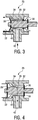
- FIG. 3 shows the influx of air through the discharge channel 32 on the valve piston 26 along through Valve housing 32 in the liquid inlet 20.
- the flexibility of the disc 28 is dimensioned so that the negative pressure lifts its edge from the valve seat 34.
- the rounded seat shoulder 40 additionally facilitates the inflow of air into the liquid inlet 20.
- the balance of the spring force of the compression spring 50 and the closing force S causes the valve piston 26 is not displaced in particular in the overpressure direction and thus prevents the influx of air. Only the dimensioning of the disc 28 thus ensures an automatic negative pressure compensation, without the bidirectional valve 23 would have to be operated separately.
- FIG. 4 shows the fully open valve 23 at overpressure.
- the disc 28 also deforms, now in the opposite direction as in FIG. 3 ,
- the valve piston 26 thus has to travel a certain distance before the valve 23 opens. It must be taken into account in the dimensioning of the compression spring 50 and the levers 46, 48.
- the pressurized steam can flow around the disc 28 with the valve 23 open, flow into the valve housing 32 and around the valve piston 26 and be discharged via the discharge channel 42 into the environment.
- the discharge channel may for example be directed vertically downwards into a provided beverage container or be directed into an overflow basin below a storage level of a beverage container.
- the spring 50 sealingly presses the annular disc 30 against its valve seat 36 so that the vapor can not escape in a direction parallel to the direction of movement A of the valve piston 26 and thus possibly to a user.
- bidirectional valve Since the preceding, described in detail bidirectional valve is an embodiment, it can in the usual way by those skilled in a wide Scope be modified without departing from the scope of the invention.
- the specific embodiment of the valve mechanism can take place in a different form than that described here.
- the mechanical coupling can be configured in another form, if this is necessary for reasons of space or designerischen reasons.
- the use of the indefinite article "on” or “one” does not exclude that the characteristics in question may also be present multiple times.
Landscapes
- Engineering & Computer Science (AREA)
- Food Science & Technology (AREA)
- Apparatus For Making Beverages (AREA)
- Cookers (AREA)
Description
- Die Erfindung betrifft eine Getränkemaschine mit einem Wassertank, einer Heizeinrichtung, insbesondere einem massearmen Durchlauferhitzer, und einer Brühkammer, die durch jeweils dazwischen angeordnete Leitungsabschnitte miteinander verbunden sind. Stromauf der Brühkammer umfasst sie zumindest ein druckabhängig selbsttätig schaltendes Ventil, das als Überdruckventil insbesondere stromauf der Heizung und/oder als Unterdruckventil an einer beliebigen Stelle im Leitungsbereich stromauf der Brühkammer ausgebildet sein kann. Die Erfindung betrifft außerdem ein Mehrfunktionenventil und die Verwendung eines druckabhängig selbsttätig schaltenden Ventils als druckunabhängig betätigbares Ventil zum Überdruckabbau.
- Aus
US 3 374 805 A ist ein Überdruckventil bekannt, das automatisch, oder per Betätigung von Hand zum Abbau eines Überdrucks in einem Behälter geeignet ist. Ein ähnliches Überdruckventil in der Wasser-Ablassleitung eines Getränkewärmers, das zusätzlich per Hand als Ablassventil für Flüssigkeiten betätig werden kann, ist z.B. aus derDE 37 41 992 A1 bekannt. - Dazu ist aus
WO-A-2007/014891 der Fluidplan eines Getränkebereiters mit einer Pumpe, einem zwischen der Pumpe und einem Flüssigkeitserhitzer angeordnetem Vibrationsdämpfungsventil, und einer zwischen dem Flüssigkeitserhitzer und verschiedenen Flüssigkeitsabgabeeinrichtungen angeordneten Ventilträgereinheit bekannt. An dieser Ventilträgereinheit sind dabei unterschiedliche Ventile in einem Gehäuse angeordnet, die verschiedene Funktionen übernehmen. So ist an der Ventilträgereinheit ein Überdruckventil angeordnet, welches zusätzlich mittels eines Elektromagnets geöffnet werden kann, um eventuellen Überdruck in Richtung eines Entspannungsbehälters abzubauen. Zusätzlich sind in dem Gehäuse weitere Ventile angeordnet, die bei verschiedenen Systemdrücken öffnen, so wie ein Ventil zum steuern des Getränkeflusses zu einer Verteilereinrichtung. - Die
DE 66 07 409 U1 beschreibt ein Unterdruckventil in einer Kaffeemaschine unter anderem zwischen einer Heizeinrichtung und einem Aufgusstrichter. Prinzipiell dem gleichen Zweck dienen Unterdruckventile in Kaffeepadmaschinen oder Mehrgetränkemaschinen. Darin können Getränke zubereitet werden, die durch Verdünnung oder Eluation von in Kapseln oder Pads enthaltenen Konzentraten mit heißem Wasser entstehen. Gegen ein Nachtropfen der benutzten Kapseln oder Pads beim Entnehmen und um Konzentrat zu sparen, sollen die Kapseln vollständig geleert und die Pads nicht mehr tropfnass sein. Dazu kann ein Dampfstoß dienen, der zumindest bei Verwendung eines massearmen Durchlauferhitzers oder eines Thermoblocks als Heizeinrichtung durch ein frühzeitiges Abschalten der Wasserpumpe und ein quasi schlagartiges Verdampfen des Restwassers in der Heizung erzeugt wird. Das Leitungssystem stromab der Heizung ist bei Beendigung des Zubereitungsvorgangs folglich mit Dampf gefüllt. Sinkt später die Temperatur im System unter den Siedepunkt des Wassers ab, kondensiert der Dampf in den Leitungen und sein Volumen verkleinert sich. Dadurch entsteht Unterdruck. Um einen Druckausgleich durch Ansaugen von Luft und Mitreißen von Flüssigkeitsresten aus der Brühkammer zu vermeiden, befindet sich stromauf der Brühkammer ein Rückschlagventil. Ein Druckausgleich aus der Richtung der Brühkammer ist damit verhindert, nicht aber aus der Gegenrichtung. Der Unterdruck kann dort bewirken, dass Wasser aus dem Tank durch die Pumpe hindurch bis in die Heizung und in den Leitungsabschnitt stromab der Heizeinrichtung angesaugt wird. Dasjenige Wasser aus dem Wassertank, das auf diese Weise in den Leitungsabschnitt stromab der Heizung gelangt, kann bei einem nachfolgenden Getränkezubereitungsvorgang nicht mehr erhitzt werden. Es führt zu einer verminderten Getränketemperatur und -qualität. Daher wird auch bei modernen Heißgetränkemaschinen stromauf der Brühkammer das eingangs erwähnte Unterdruckventil angeordnet, das im Unterdruckfall eine Verbindung zur Atmosphäre schafft. Bei Betriebsdruck dagegen schließt dieses Ventil sicher. - Aus Sicherheitsgründen werden andererseits Maßnahmen gegen Überdruck ergriffen. So ist aus der
DE 10 2004 046 436 A1 ein Überdruckventil stromauf der Heizung bekannt. DieDE10 2004 004 833 A1 offenbart einen Sicherheitsschalter an der Brühkammer, der einen Betrieb der Getränkemaschine bei geöffneter Brühkammer durch Abschalten der Heizung und/oder Fördereinrichtung verhindert. Diese Maßnahme kann aber zum Beispiel bei einer Getränkemaschine mit einem aufwärts in die Brühkammer gerichteten Wasserzulauf, wie sie dieEP 1 440 910 A1 offenbart, ungenügend sein. Wenn sie nur leicht verzögert anspricht, können bei einem vorzeitigen Öffnen der Brühkammer Verletzungen des Bedieners nicht ausgeschlossen werden. - Es ist Aufgabe der Erfindung, die Funktionssicherheit einer Heißgetränkemaschine im Hinblick auf die dargelegten Probleme zu verbessern und insbesondere den Herstellungsaufwand zu reduzieren und zugleich Bauraum einzusparen.
- Diese Aufgabe kann dadurch gelöst werden, dass das an sich selbsttätig und druckabhängig schaltende Ventil stromauf der Brühkammer zusätzlich druckunabhängig betätigbar ist. Es öffnet also nicht nur ab einem bestimmten anliegenden Über- oder Unterdruck automatisch, sondern kann zusätzlich quasi auf Anforderung in einem separaten Betätigungsvorgang geöffnet werden. Die Erfindung verfolgt also das Prinzip, ein druckabhängig arbeitendes Ventil zusätzlich auch druckunabhängig schaltbar auszurüsten. Dafür umfasst das Ventil erfindungsgemäß eine Betätigungseinrichtung, die beispielsweise aus Sicherheitsgründen eine weitere und druckunabhängige Schaltung des Ventils ermöglicht. Anstatt ein eigenes Ventil dafür vorzusehen, kann das bereits vorhandene Ventil diese Funktion zusätzlich übernehmen. Diese Funktionenkombination in einem Mehrfunktionenventil spart Material- und Montagekosten sowie Bauraum ein.
- Prinzipiell kann das selbsttätig druckabhängig schaltende Ventil als Überdruck- oder als Unterdruckventil ausgebildet sein.
- Erfindungsgemäß ist ein selbsttätig druckabhängig schaltendes Unterdruckventil stromauf der Brühkammer angeordnet, das bei Vorliegen eines Überdrucks auch in der Gegenrichtung zur Durchgangsrichtung des Ventils bei Unterdruck durchgängig ist. Es wirkt also zugleich, aber nicht gleichzeitig sowohl wie ein bekanntes Unterdruck- als auch wie ein Überdruckventil, und zwar zum Abbau eines überschüssigen und den Benutzer gegebenenfalls gefährdenden Überdrucks. Die Erfindung verfolgt also auch hier das Prinzip einer Funktionenkombination, indem ein Ventil sowohl als Unterdruck- als auch als Überdruckventil fungiert. Dieses Mehrfunktionenventil ist dazu als Zweirichtungsventil ausgebildet, das in der einen Durchgangsrichtung auf Unterdruck anspricht und in der Gegenrichtung zum Abbau von Überdruck dient. Durch die Doppelfunktion des Ventils kann wiederum der Herstellungsaufwand reduziert und zugleich Bauraum eingespart werden. Dieses Mehrfunktionenventils wird im Folgenden als "Zweirichtungsventil" bezeichnet.
- Nach einer vorteilhaften Ausgestaltung der Erfindung kann das Zweirichtungsventil für einen Durchgang entgegen der Unterdruckrichtung betätigbar sein. Im Gegensatz zur Funktion als Unterdruckventil, in der es aufgrund des anliegenden Unterdrucks, also druckabhängig und selbsttätig schaltet und den gewünschten Druckausgleich erzielt, wird es im Falle des Überdruckabbaus in einem eigenen Betätigungsvorgang und druckunabhängig aktiviert. Es verfügt dazu über eine Betätigungseinrichtung für seine Bedienung im Überdruckfall.
- Das Mehrfunktionenventile (Zweirichtungsventil) wird vorzugsweise dazu eingesetzt, den Überdruck aus dem System abzuleiten, wenn die Brühkammer während des Brühbetriebs versehentlich vorzeitig geöffnet wird. Aus Sicherheitsgründen soll der Überdruck dann nämlich nicht über den herkömmlichen Weg durch die Brühkammer und damit dem Benutzer zugewandt abgeleitet werden, sondern in einem dem Benutzer möglichst abgewandten Bereich der Getränkemaschine abgebaut werden. Dadurch kann Schaden in Folge einer Fehlbedienung vom Benutzer abgewendet werden.
- Nach einer weiteren vorteilhaften Ausgestaltung der Erfindung kann das Zweirichtungsventil mit der Brühkammer mechanisch oder elektrisch gekoppelt sein, so dass es für einen Durchgang in der Überdruckrichtung geöffnet ist, sobald die Brühkammer geöffnet ist. Dadurch wird also ein Automatismus zwischen einem vorzeitigen oder generellen Öffnen der Brühkammer und einem Öffnen des Überdruckventils hergestellt. Die direkte Kopplung des Ventils mit der Brühkammer hat zur Folge, dass es zuverlässig öffnet, sobald die Brühkammer geöffnet wird. Sie bietet dadurch eine zusätzliche Sicherheit, weil das Öffnen des Überdruckventils an das Öffnen der Brühkammer und nicht zwingend an das Vorliegen eines Überdrucks gekoppelt ist. Denn ein Öffnen des Ventils ohne das Anliegen von Überdruck ist unschädlich, wohingegen ein Nichtöffnen des Ventils bei anliegendem Überdruck dem Benutzer beim Öffnen der Brühkammer schaden könnte.
- Nach einer vorteilhaften Ausgestaltung der Erfindung kann das Mehrfunktionenventil mit der Brühkammer elektronisch gekoppelt sein. Dadurch kann die Konstruktion des Auslösemechanismus einfacher gestaltet und gegebenenfalls Platz eingespart werden. Außerdem kann das Auslösen des Ventils an weitere Bedingungen geknüpft werden, also nicht nur an das Öffnen der Brühkammer, sondern zum Beispiel an das Vorliegen eines bestimmten minimalen Überdrucks, ab dem eine Überdruckentlastung notwendig und sinnvoll erscheint. Der Überdruck kann sensorisch erfasst werden kann. Eine elektrische Kopplung zwischen dem erfinderischen Ventil und der Brühkammer kann zudem besonders dann vorteilhaft sein, wenn sie räumlich weit auseinander liegen. Die räumliche Distanz kann dann über elektrische Leiter überbrückt werden oder das Ventil und die Brühkammer können jeweils mit einer Steuerungseinrichtung verbunden sein. Eine größere räumliche Distanz zwischen der Brühkammer und dem Ventil kann vorliegen, wenn das Ventil in dem Leitungsabschnitt zwischen dem Wassertank und der Heizung angeordnet ist. Als herkömmliches Überdruckventil verhindert es dort einen Überdruckaufbau, falls sich in der Heizung ein Wasserstau infolge Verkalkung aufbauen sollte.
- Eine Kopplung zwischen der Brühkammerbetätigung und dem Mehrfunktionenventil kann nach einer dazu alternativen Ausgestaltungsform der Erfindung mechanisch erfolgen. Dadurch kann eine hohe Zuverlässigkeit des Auslösevorgangs des Ventils im Überdruckfall erzielt werden. Eine mechanische Kopplung kann für das Zweirichtungsventil vorteilhaft sein, das in räumlicher Nähe zur Brühkammerbetätigung angebracht, also insbesondere in dem Leitungsabschnitt stromab der Heizeinrichtung und stromauf der Brühkammer angeordnet ist. Sowohl Überdruckventile als auch Unterdruckventile sollen möglichst schnell ansprechen. Je weiter entfernt sie von der Brühkammer platziert werden, umso eher besteht die Gefahr, dass sich Wasser in dem Leitungsabschnitt zwischen ihnen und der Brühkammer befindet. Das Wasser mit seiner relativ hohen Masse kann aber verzögernd auf die Aktivierung des Unterdruckventils und störend beim Überdruckabbau wirken. Sowohl Unterdruck- als auch Überdruckventile werden daher vorzugsweise möglichst in unmittelbarer Nähe zur Brühkammer platziert. Auch insofern ist eine Kombination beider Ventilteile zu einem gemeinsamen Funktionsbauteil als Zweirichtungsventil günstig.
- Für Unter- oder Überdruckventile sind Mechanismen bekannt, bei denen zum Beispiel eine Kugel gegen Federkraft dichtend auf einen Ventilsitz gedrückt wird. Übersteigt die Unter- oder Überdruckkraft die Federkraft, so löst der anliegende Druck die Kugel vom Ventilsitz und öffnet das Ventil entgegen der Federkraft. Für eine Ausbildung als Mehrfunktionenventil kann an der Kugel eine Betätigungseinrichtung angeordnet sein, mit deren Hilfe die Kugel entgegen der Federkraft verschoben werden und damit das Ventil geöffnet werden kann.
- Nach einer vorteilhaften Ausgestaltung der Erfindung umfasst das Ventil als abdichtendes Element eine flexible Scheibe, die auf einem Ventilsitz aufliegt und bei Unterdruck unter Verformung, aber ohne Verschiebung vom Ventilsitz abgehoben ist. Auch dadurch kann ein selbsttätiger Unterdruckausgleich erzielt werden, wobei in der flexiblen Scheibe das die Öffnungskraft des Ventils im Unterdruckfall definierende elastische Element einerseits und der Ventilkörper andererseits kombiniert sind. Dadurch lässt sich ein besonders kompakter Aufbau für das Zweirichtungsventil erzielen. Als Material für die Scheibe eignet sich Silikon besonders gut, weil sich daran keine Ablagerungen bilden. Das Ventil ist dadurch unanfällig gegen Verkalken.
- Nach einer weiteren vorteilhaften Ausgestaltung der Erfindung kann bei einer Überdruckbetätigung des Ventils die flexible Scheibe verschoben und vom Ventilsitz abgehoben sein. Im Überdruckfall wird das Ventil entgegen der Überdruckrichtung geöffnet, die flexible Scheibe also entgegen der Druckrichtung vom Ventilsitz abgehoben. Da sich auch dabei die flexible Scheibe verformen kann, ist der Betätigungsweg ausreichend lang zu bemessen, um die Scheibe vollständig vom Ventilsitz abzuheben.
- Die eingangs genannte Aufgabe wird außerdem durch ein Mehrfunktionenventil gelöst, das druckabhängig selbsttätig zugleich, aber nicht gleichzeitig als Unterdruckventil als auch wie ein Überdruckventil wirkt und zusätzlich vorzugsweise in Überdruckrichtung druckunabhängig betätigbar ist. Wesentlich ist jedenfalls, dass das an sich selbsttätig schaltende Ventil zusätzlich in Überdruckrichtung betätigbar ist und dafür eine Betätigungseinrichtung umfasst. Diese Funktionskombination erspart Herstellungs- und Montageaufwand.
- Die eingangs genannte Aufgabe wird außerdem durch die Verwendung eines an sich bekannten, druckabhängig selbsttätig schaltenden Ventils, das zugleich, aber nicht gleichzeitig als Unterdruckventil als auch wie ein Überdruckventil wirkt, zwischen einem Wassertank und einer Brühkammer in einer Getränkemaschine gelöst, indem es zugleich als druckunabhängig betätigbares Überdruckventil dient. Die Erfindung verfolgt also das Prinzip einer Funktionskombination eines Ventils als automatisch schaltendes Ventil einerseits und zusätzlich betätigbares Dampfableitventil andererseits. Für eine Überdruckentlastung jedenfalls ist es in beiden Fällen unabhängig vom aktuell vorliegenden Druck in einem eigenen Betätigungsvorgang zu schalten.
- Das Ventil wirkt damit also als Mehrfunktionenventil, muss dafür aber selbst nicht wesentlich umgestaltet sein. Es genügt beispielsweise die Anbringung einer
- Betätigungseinrichtung am Ventilkörper, mit der das Ventil entgegen der Überdruckrichtung geöffnet werden kann.
- Nach einer vorteilhaften Ausgestaltung der erfindungsgemäßen Verwendung wird das Mehrfunktionenventil dann zur Dampfableitung verwendet, sobald die Brühkammer geöffnet wird. Dadurch kann insbesondere bei einer Fehlbedienung der Getränkemaschine während eines Zubereitungsvorganges Schaden vom Benutzer abgewendet werden.
- Das Prinzip der Erfindung wird im Folgenden anhand einer Zeichnung beispielshalber noch näher erläutert. In der Zeichnung zeigen:
- Figur 1
- einen schematischen Aufbau einer Getränkezubereitungsmaschine,
- Figur 2
- eine Detailansicht des Zweirichtungsventils samt Betätigungsvorrichtung,
- Figur 3
- eine Schnittansicht des Ventils im Unterdruckfall, und
- Figur 4
- eine Schnittansicht des Ventils im Überdruckfall.
- Prinzipiell umfasst eine Pad- oder Mehrgetränkemaschine gemäß
Figur 1 einen Frischwassertank 1, der Frischwasser über einen Flüssigkeitszulauf 2 durch einen Durchflusszähler 3 und eine Pumpe 4 in eine Heizungseinrichtung 5 leitet. Die Pumpe 4 ist zugleich als Rücklaufsperre ausgebildet, damit das Wasser durch den Druck infolge seiner Erwärmung in der Heizeinrichtung 5 bei deaktivierter Pumpe 4 nicht in den Wassertank 1 zurück, sondern in Richtung einer Brühkammer 10 gefördert wird. Zwischen der Pumpe 4 und der Heizeinrichtung 5 ist ein druckabhängig öffnendes Überdruckventil 6 angeordnet, das einen ggf. entstehenden Überdruck zwischen dem Frischwassertank 1 und der Heizeinrichtung 5 über eine Rücklaufleitung 7 in den Frischwasserbehälter 1 ableitet. Erfindungsgemäß kann es zusätzlich druckunabhängig geschaltet werden. In dem dargestellten Aufbau dient es jedoch ausschließlich dem druckabhängigen Überdruckabbau infolge von beispielsweise verkalkungsbedingten Druckstörungen in der Heizeinrichtung 5. - Stromab der Heizeinrichtung 5 ist ein Temperatursensor 8 angeordnet. Ihm folgt stromab im Flüssigkeitszulauf 2 unmittelbar vor der Brühkammer 10 eine Rücklaufsperre 9.
- Zwischen dem Temperatursensor 8 und der Rücklaufsperre 9 befindet sich ein Abzweig 11, der eine Ableitung 12 in die Atmosphäre an den Flüssigkeitszulauf 2 anschließt. In der Ableitung 12 ist ein Zweirichtungsventil 13 als Mehrfunktionenventil angeordnet.
- Für eine Getränkezubereitung führt die Pumpe 4 Frischwasser aus dem Wassertank 1 in die Heizung 5. Dort wird es erhitzt und der Brühkammer 10 zugeführt. Für eine exakte Füllmenge bzw. Dosierung des Brühwassers sorgt der Durchflusszähler 3, die erforderliche Temperatur für eine erfolgreiche Zubereitung des Getränks überwacht der Temperatursensor 8. Am Ende eines Brühvorganges schaltet die Pumpe 4 den Wasservorschub aus, während die Heizung 5 noch weiterläuft. Das noch in der Heizung 5 befindliche Wasser wird aufgrund des fehlenden kühlen nachströmenden Wassers schnell in Dampf umgewandelt und bewirkt einen Dampfdruck, der die Flüssigkeitsreste stromab der Heizung 5 im Flüssigkeitszulauf 2 durch die Brühkammer 12 in eine bereitgestellte Tasse drückt. Der Dampfdruck spült außerdem Flüssigkeitsreste einer Getränkekapsel in der Brühkammer 10 aus bzw. trocknet ein in der Brühkammer 10 befindliches Getränkepad. Ein Nachtropfen bei der Entnahme eines gebrauchten Pads bzw. der Getränkekapsel kann dadurch weitgehend vermieden werden, was die Bedienung der Getränkemaschine vereinfacht.
- Sobald nach Abschluss des Getränkezubereitungsvorgangs die Heizeinrichtung 5 abgeschaltet ist, kühlt der Dampf in der Zuleitung 2 stromab der Heizung 5 ab. Sein Volumen verringert sich, wodurch im Leitungsabschnitt 2 stromauf der Brühkammer 10 ein Unterdruck entsteht. Damit dieser Unterdruck keine Flüssigkeits- oder Substratreste aus der Brühkammer 10 in die Frischwasserzuleitung 2 ansaugt, verhindert das Rückschlagventil 9 einen Druckausgleich über die Brühkammer 10. Es kann z. B. als elastische geschlitzte Membran ausgebildet sein. Durch Alterung oder Fertigungstoleranzen kann jedoch ihre Funktion leiden, so dass sie nicht mehr vollständig luftdicht ist. Um einen Druckausgleich aus der Brühkammer 10 dennoch zu vermeiden, wird er gezielt über die Ableitung 12 hergestellt. Baut sich also ein Unterdruck im Flüssigkeitszulauf 2 auf, so wird er frühzeitig über das dann als Unterdruckventil fungierende Zweirichtungsventil 13 abgebaut.
- Nicht nur durch den Druck der Pumpe 4 während der Getränkezubereitung, sondern vor allem durch das in der Heizung 5 erhitzte Wasser, insbesondere am Ende eines Zubereitungsvorgangs, entsteht im Flüssigkeitszulauf 2 ein erheblicher Druck bis hin zum Dampfstoß als Abschluss eines Zubereitungsvorgangs. Dieser Druck kann einem Benutzer bei einer Fehlbedienung der Getränkemaschine gefährlich werden. Öffnet er versehentlich und fälschlicherweise frühzeitig die Brühkammer 10, so kann er sich an dem sofort austretenden Dampf empfindlich verbrühen. Um dem entgegenzuwirken, dient das Zweirichtungsventil 13 nicht nur als Unterdruckventil, sondern auch als Dampfableitventil bei einer vorzeitigen Öffnung der Brühkammer 10. Es ist dazu mit der Brühkammer 10 mechanisch gekoppelt, so dass es öffnet, sobald die Brühkammer 10 geöffnet wird. Aufgrund des geringeren Widerstands im Leitungsweg der Ableitung 12 entweicht der Dampfdruck im Wesentlichen über das Zweirichtungsventil 13 und bestenfalls in nur noch vernachlässigbarem Umfang über die Brühklammer 10. Die Mündung der Ableitung 12 ist zur Sicherheit des Benutzers von ihm abgewandt an der Getränkemaschine angeordnet, so dass der abgeleitete Dampf den Benutzer nicht trifft.
- Der Abzweig 11 für die Ableitung 12 ist in unmittelbarer Nähe der Brühkammer 10 angeordnet. Dies ermöglicht eine kompakte Ausbildung der Brühkammer 10 und des Zweirichtungsventils 13. Die Nähe zur Brühkammer 10 vereinfacht außerdem die mechanische Kopplung des Zweirichtungsventils 13 als Dampfableitventil mit einer Öffnungs- und Verschließbetätigung der Brühkammer 10.
- Ein Konstruktionsbeispiel für einen Leitungsabschnitt mit einem Zweirichtungsventil 23 zeigt
Figur 2 : Ein Flüssigkeitszulauf 20 teilt sich in einem Abzweigebereich 21 in einen Zulauf 24 zu einer Brühkammer bzw. zu einer vorgeschalteten Rücklaufsperre und in einen in Achsrichtung des Zulaufs 20 anschließenden Ableitungsabschnitt 22. Er mündet an dem Zweirichtungsventil 23. - Das Zweirichtungsventil 23 umfasst einen Ventilkolben 26, der auf seiner dem Flüssigkeitszulauf 20 zugewandten Seite eine flexible Silikonscheibe 28 als Ventilkörper trägt. An seinem gegenüberliegenden, dem Flüssigkeitszulauf 20 abgewandten Ende trägt der Ventilkörper 26 eine Dichtscheibe 30, ebenfalls aus Silikon. Der Ventilkolben 26 wird von einem zylindrischen Ventilgehäuse 32 umgeben, das an seinen Stirnseiten jeweils einen Ventilsitz 34 für die Scheibe 28 und einen Ventilsitz 36 für die Scheibe 30 ausbildet. Die Ventilsitze 34, 36 bilden also einen ringförmigen Kragen, wobei der Ventilsitz 36 eine in der Schnittansicht rechtwinklige Sitzkante 38 aufweist, wohingegen der Ventilsitz 34 eine abgerundete Schulter 40 ausbildet.
- Der Ventilkolben 26 gleitet im Ventilgehäuse 32. Er hat einen (nicht dargestellten) stern- oder kreuzförmigen Querschnitt mit radialen Strahlen, deren Strahlenenden im Ventilgehäuse 32 geführt werden. Das Ventilgehäuse 32 ist dadurch im Bereich des Ventilkolbens 26 in seiner Achsrichtung bzw. in der Bewegungsrichtung A des Ventilkolbens 26 durchströmbar, der Ventilkolben 26 umspülbar. Die Bewegungen des Ventilkolbens 26 innerhalb des Ventilgehäuses 32 in seinen beiden Bewegungsrichtungen A sind entweder begrenzt durch das Anliegen der Scheibe 28 an ihrem Ventilsitz 34 (vgl.
Figur 2 ) oder durch die Anlage der gegenüberliegenden Scheiben 30 auf ihrem Ventilsitz 36 (vgl.Figur 4 ). Etwa in der Mitte des zylindrischen Ventilgehäuses 32 zweigt radial ein Entlastungskanal 42 ab, der eine Verbindung vom Innenraum des Ventilgehäuses 32 zur Umgebung herstellt. - Auf der Seite der Scheibe 30 ist am Ventilkolben 26 ein Betätigungsstößel 44 angeschlossen, der sich in Bewegungsrichtung A erstreckt und über einen Drehhebel 46 mit einem federvorgespannten Betätigungshebel 48 kinematisch gekoppelt ist. Eine Druckfeder 50 spannt den Betätigungshebel 48 in eine Unterdruckrichtung U und entgegen einem Überdruck vor. Die Druckfeder 50 belastet das Zweirichtungsventil 23 also in Öffnungsrichtung bei Überdruck. Ihr wirkt eine Schließkraft S entgegen, die beim Schließen der Brühkammer 10 aktiviert wird. Die Schließkraft S resultiert aus der Verriegelung der Brühkammer im Betrieb. Das einander entgegengesetzt gerichtete, aber betragsmäßig gleich große Kräftepaar aus der Federkraft der Druckfeder 50 einerseits und der Schließkraft S andererseits gewährleistet, dass das Zweirichtungsventil 23 zuverlässig geöffnet wird, wenn der Verschluss der Brühkammer 10 aufgehoben wird, die Schließkraft S also wegfällt. Die Druckfeder 50 ist so stark zu dimensionieren, dass sie das Zweirichtungsventil 23 entgegen dem Überdruck öffnen kann. Gleich groß ist die Schließkraft S auszulegen, um das Zweirichtungsventil 23 bei verschlossener Brühkammer geschlossen zu halten.
- Entsteht im Flüssigkeitszulauf 20 bei geschlossener Brühkammer ein ungewünschter Unterdruck, so gleicht ihn das Zweirichtungsventil 23 selbsttätig aus.
Figur 3 zeigt das Einströmen von Luft durch den Ableitungskanal 32 am Ventilkolben 26 entlang durch das Ventilgehäuse 32 in den Flüssigkeitszulauf 20. Die Flexibilität der Scheibe 28 ist so bemessen, dass der Unterdruck ihren Rand vom Ventilsitz 34 abhebt. Die abgerundete Sitzschulter 40 erleichtert zusätzlich das Einströmen von Luft in den Flüssigkeitszulauf 20. Das Gleichgewicht der Federkraft der Druckfeder 50 und der Schließkraft S bewirkt, dass der Ventilkolben 26 insbesondere nicht in Überdruckrichtung verschoben wird und damit das Einströmen von Luft verhindert. Allein die Dimensionierung der Scheibe 28 sorgt also für einen selbsttätigen Unterdruckausgleich, ohne dass das Zweirichtungsventil 23 separat betätigt werden müsste. - Eine Betätigung ist dagegen erforderlich, wenn das Zweirichtungsventil 23 einen Überdruck in dem Flüssigkeitszulauf 20 abbauen soll. Beim Öffnen der Brühkammer 10 fällt die Schließkraft S weg, so dass die Druckfeder 50 den Betätigungshebel 48 in die Richtung U verschiebt. Der Drehhebel 46 verschiebt daraufhin den Ventilkolben 26 in die Gegenrichtung bis maximal zum Anschlag der Scheibe 30 auf ihrem Ventilsitz 36. Dabei wird die Scheibe 28 von ihrem Ventilsitz 34 und entgegen der Überdruckrichtung abgehoben.
-
Figur 4 zeigt das vollständig geöffnete Ventil 23 bei Überdruck. Vorher jedoch, beim Beginn der Verschiebungsbewegung des Ventilkolbens 26, verformt sich die Scheibe 28 ebenfalls, jetzt in der entgegengesetzten Richtung wie inFigur 3 . Der Ventilkolben 26 muss also eine gewisse Wegstrecke zurücklegen, bevor das Ventil 23 öffnet. Sie muss bei der Dimensionierung der Druckfeder 50 und der Hebel 46, 48 berücksichtigt werden. - Der unter Überdruck stehende Dampf kann bei geöffnetem Ventil 23 die Scheibe 28 umfließen, in das Ventilgehäuse 32 und um den Ventilkolben 26 herum einströmen und über den Ableitungskanal 42 in die Umgebung abgegeben werden. Der Ableitungskanal kann zum Beispiel senkrecht abwärts in ein bereitgestelltes Getränkegefäß gerichtet sein oder in ein Überlaufbecken unterhalb einer Abstellebene eines Getränkegefäßes geleitet werden. Die Feder 50 drückt die ringförmige Scheibe 30 dichtend auf ihren Ventilsitz 36, so dass der Dampf nicht in einer Richtung parallel zur Bewegungsrichtung A des Ventilkolbens 26 und damit möglicherweise auf einen Benutzer hin entweichen kann.
- Da es sich bei dem vorhergehenden, detailliert beschriebenen Zweirichtungsventil um ein Ausführungsbeispiel handelt, kann es in üblicher Weise vom Fachmann in einem weiten Umfang modifiziert werden, ohne den Bereich der Erfindung zu verlassen. Insbesondere kann die konkrete Ausgestaltung des Ventilmechanismus in anderer Form als in der hier beschriebenen erfolgen. Ebenso kann die mechanische Kopplung in einer anderen Form ausgestaltet werden, wenn dies aus Platzgründen bzw. designerischen Gründen notwendig ist. Weiterhin schließt die Verwendung der unbestimmten Artikel "ein" bzw. "eine" nicht aus, dass die betreffenden Merkmale auch mehrfach vorhanden sein können.
-
- 1
- Frischwassertank
- 2
- Flüssigkeitszulauf
- 3
- Durchflusszähler
- 4
- Pumpe
- 5
- Heizung
- 6
- Überdruckventil
- 7
- Rücklaufleitung
- 8
- Temperatursensor
- 9
- Rückschlagventil
- 10
- Brühkammer
- 11
- Abzweigung
- 12
- Ableitungskanal
- 13
- Zweirichtungsventil
- 20
- Flüssigkeitszulauf
- 21
- Abzweigung
- 22
- Ableitungsabschnitt
- 23
- Zweirichtungsventil
- 24
- Zulauf zur Brühkammer
- 26
- Ventilkolben
- 28
- flexible Silikonscheibe
- 30
- Ringscheibe
- 32
- Ventilgehäuse
- 34
- Ventilsitz
- 36
- Ventilsitz
- 38
- Sitzkante
- 40
- Sitzschulter
- 42
- Ableitungskanal
- 44
- Betätigungsstößel
- 46
- Drehhebel
- 48
- Betätigungshebel
- 50
- Druckfeder
- A
- Betätigungsrichtungen des Ventilkolbens 26
- U
- Betätigungsrichtung bei Überdruck
- S
- Schließkraft
Claims (9)
- Getränkemaschine mit einem Wassertank (1), einer Heizeinrichtung (5) und einer Brühkammer (10), die durch jeweils dazwischen angeordnete Leitungsabschnitte (2) miteinander verbunden sind, und mit einem druckabhängig selbsttätig schaltenden Ventil (13; 23) in dem Leitungsabschnitt (2) zwischen Wassertank (1) und Brühkammer (10), dadurch gekennzeichnet, dass das Ventil ein druckabhängig selbsttätig schaltendes Unterdruckventil (13; 23) in einem der Leitungsabschnitte (2) vor der Brühkammer (10) ist, und dass das Unterdruckventil (13; 23) bei Überdruck in Gegenrichtung zur Durchgangsrichtung bei Unterdruck, also in Überdruckrichtung durchgängig ist.
- Getränkemaschine nach Anspruch 1, dadurch gekennzeichnet, dass das Ventil (13) für einen Durchgang entgegen der Unterdruckrichtung betätigbar ist.
- Getränkemaschine nach einem der obigen Ansprüche, dadurch gekennzeichnet, dass das Ventil (6; 13; 23) mit der Brühkammer (10) gekoppelt ist, so dass es für einen Durchgang in der Überdruckrichtung geöffnet ist, sobald die Brühkammer (10) geöffnet ist.
- Getränkemaschine nach Anspruch 3, dadurch gekennzeichnet, dass das Ventil (6; 13) mit der Brühkammer elektrisch gekoppelt ist.
- Getränkemaschine nach Anspruch 3, dadurch gekennzeichnet, dass das Ventil (6; 13; 23) mit der Brühkammer (10) mechanisch gekoppelt ist.
- Getränkemaschine einem der Ansprüche 1 bis 5, dadurch gekennzeichnet, dass das Ventil (23) als abdichtendes Element eine flexible Scheibe (28) umfasst, die auf einem Ventilsitz (34) liegt und die unter Verformung vom Ventilsitz (34) abhebbar ist.
- Getränkemaschine nach Anspruch 6, dadurch gekennzeichnet, dass die flexible Scheibe (28) bei einer Überdruck-Betätigung des Ventils (23) durch eine Verschiebung vom Ventilsitz (34) abhebbar ist.
- Mehrfunktionenventil (13; 23), das druckabhängig selbsttätig zur Unterdruckentlastung schaltet und zusätzlich in Überdruckrichtung druckunabhängig betätigbar ist, zum Einsatz in einer Getränkemaschine.
- Verwendung eines Mehrfuntionenventils nach Anspruch 8 in einem Leitungsweg (2) einer Getränkemaschine zwischen einem Wasservorratstank (1) und einer Brühkammer (10) als Dampfableitventil für einen Überdruckabbau, sobald die Brühkammer (10) geöffnet wird.
Applications Claiming Priority (1)
| Application Number | Priority Date | Filing Date | Title |
|---|---|---|---|
| DE102007058375A DE102007058375A1 (de) | 2007-12-05 | 2007-12-05 | Getränkemaschine mit einem Mehrfunktionenventil |
Publications (3)
| Publication Number | Publication Date |
|---|---|
| EP2067423A2 EP2067423A2 (de) | 2009-06-10 |
| EP2067423A3 EP2067423A3 (de) | 2015-02-25 |
| EP2067423B1 true EP2067423B1 (de) | 2017-01-11 |
Family
ID=40404114
Family Applications (1)
| Application Number | Title | Priority Date | Filing Date |
|---|---|---|---|
| EP08105737.4A Not-in-force EP2067423B1 (de) | 2007-12-05 | 2008-11-05 | Getränkemaschine mit einem Mehrfunktionenventil |
Country Status (3)
| Country | Link |
|---|---|
| EP (1) | EP2067423B1 (de) |
| CN (1) | CN101449928B (de) |
| DE (1) | DE102007058375A1 (de) |
Cited By (4)
| Publication number | Priority date | Publication date | Assignee | Title |
|---|---|---|---|---|
| EP4201274A1 (de) | 2021-12-23 | 2023-06-28 | BSH Hausgeräte GmbH | Kaffeemaschine mit druckentlastungsventil |
| US12369741B1 (en) | 2024-01-18 | 2025-07-29 | Sharkninja Operating Llc | Preventing coffee bean grinder jamming |
| US12369744B1 (en) | 2024-01-18 | 2025-07-29 | Sharkninja Operating Llc | Preparation of beverage machines for cold beverage brewing |
| US12575692B2 (en) | 2024-01-18 | 2026-03-17 | Sharkninja Operating Llc | Suggesting coffee bean grind size for beverage machines |
Families Citing this family (13)
| Publication number | Priority date | Publication date | Assignee | Title |
|---|---|---|---|---|
| DE102009055384A1 (de) * | 2009-12-29 | 2011-06-30 | BSH Bosch und Siemens Hausgeräte GmbH, 81739 | Heißgetränkemaschine mit einer Ventilanordnung |
| US9723945B2 (en) * | 2010-11-26 | 2017-08-08 | Koninklijke Philips N.V. | Device for making a beverage adapted to accurately set a dispense temperature of the beverage |
| DE102011084424B4 (de) * | 2011-10-13 | 2019-11-07 | Ecm Espresso Coffee Machines Manufacture Gmbh | Kaffeemaschine |
| DE102011084839B4 (de) | 2011-10-20 | 2017-06-14 | BSH Hausgeräte GmbH | Ventilanordnung mit Sperreinrichtung |
| JP2014050578A (ja) * | 2012-09-07 | 2014-03-20 | Zojirushi Corp | 飲料抽出機 |
| CN103799880A (zh) * | 2012-11-08 | 2014-05-21 | 伊莱克斯(中国)电器有限公司 | 咖啡机中的水箱连接件 |
| DE102014206487B4 (de) | 2014-04-04 | 2020-07-09 | BSH Hausgeräte GmbH | Heißgetränkezubereitungseinrichtung mit Überdruckventil |
| CN105485994A (zh) * | 2016-01-13 | 2016-04-13 | 德清武康雪之美厨房设备厂 | 一种口味雪花机的桶灌装封闭式下液装置 |
| IT201600083066A1 (it) * | 2016-08-05 | 2018-02-05 | Lavazza Luigi Spa | Macchina per la preparazione di bevande, in particolare caffe' espresso, e dispositivo di auto-innesco utilizzabile in una tale macchina |
| FR3086152B1 (fr) * | 2018-09-24 | 2020-09-18 | Seb Sa | Machine de preparation de boissons avec dispositif d'agitation rotatif et clapet de mise a l'air d'un conduit d'acheminement d'eau chaude et/ou de vapeur |
| EP3669717A1 (de) | 2018-12-17 | 2020-06-24 | Koninklijke Philips N.V. | Kaffeemaschine mit integriertem wasserdampf und heisswassererzeugung |
| CN111297199A (zh) * | 2020-03-13 | 2020-06-19 | 宁波凯波集团有限公司 | 热水阀组及饮料冲泡设备 |
| DE102020131306A1 (de) | 2020-11-26 | 2022-06-02 | A. u. K. Müller GmbH & Co KG. | Druckausgleichsvorrichtung |
Family Cites Families (10)
| Publication number | Priority date | Publication date | Assignee | Title |
|---|---|---|---|---|
| US3374805A (en) * | 1965-08-16 | 1968-03-26 | Kelsey Hayes Co | Pressure relief valve |
| DE6607409U (de) | 1966-12-17 | 1971-03-04 | Siemens Elektrogeraete Gmbh | Elektrische kaffeemaschine mit druckbeaufschlagtem foerdersystem |
| DE3741922C2 (de) * | 1987-12-10 | 1996-07-18 | Bosch Siemens Hausgeraete | Getränkewärmer, insbesondere zur Verwendung im Haushalt |
| IN192798B (de) * | 2000-03-15 | 2004-05-22 | Fianara Int Bv | |
| DE20217068U1 (de) * | 2002-11-04 | 2004-03-18 | Eugster/Frismag Ag | Einrichtung zum Ableiten von Restdampf und Restwasser aus dem Heizer einer Heißgetränkemaschine, insbesondere Kaffeemaschine |
| GB2397505B (en) | 2003-01-24 | 2006-01-04 | Kraft Foods R & D Inc | System and method for the preparation of beverages |
| DE102004004833A1 (de) | 2004-01-30 | 2005-08-18 | BSH Bosch und Siemens Hausgeräte GmbH | Kaffeemaschine mit einer Schublade zum Zuführen eines Kaffeepads |
| DE102004046436A1 (de) | 2004-09-24 | 2006-04-13 | BSH Bosch und Siemens Hausgeräte GmbH | Kaffeemaschine mit Durchlauferhitzer |
| ITFI20050169A1 (it) * | 2005-07-27 | 2007-01-28 | Saeco Ipr Ltd | Circuito idraulico per macchine da bevande espresso, valvola di scarico e sicurezza per detto circuito e relativo metodo per produzione di bevande espresso |
| CN2931999Y (zh) * | 2006-05-30 | 2007-08-08 | 广东亿龙电器股份有限公司 | 压力咖啡机用的阀装置 |
-
2007
- 2007-12-05 DE DE102007058375A patent/DE102007058375A1/de not_active Withdrawn
-
2008
- 2008-11-05 EP EP08105737.4A patent/EP2067423B1/de not_active Not-in-force
- 2008-12-05 CN CN200810179816.XA patent/CN101449928B/zh not_active Expired - Fee Related
Non-Patent Citations (1)
| Title |
|---|
| None * |
Cited By (4)
| Publication number | Priority date | Publication date | Assignee | Title |
|---|---|---|---|---|
| EP4201274A1 (de) | 2021-12-23 | 2023-06-28 | BSH Hausgeräte GmbH | Kaffeemaschine mit druckentlastungsventil |
| US12369741B1 (en) | 2024-01-18 | 2025-07-29 | Sharkninja Operating Llc | Preventing coffee bean grinder jamming |
| US12369744B1 (en) | 2024-01-18 | 2025-07-29 | Sharkninja Operating Llc | Preparation of beverage machines for cold beverage brewing |
| US12575692B2 (en) | 2024-01-18 | 2026-03-17 | Sharkninja Operating Llc | Suggesting coffee bean grind size for beverage machines |
Also Published As
| Publication number | Publication date |
|---|---|
| EP2067423A3 (de) | 2015-02-25 |
| DE102007058375A1 (de) | 2009-06-10 |
| CN101449928A (zh) | 2009-06-10 |
| CN101449928B (zh) | 2015-11-25 |
| EP2067423A2 (de) | 2009-06-10 |
Similar Documents
| Publication | Publication Date | Title |
|---|---|---|
| EP2067423B1 (de) | Getränkemaschine mit einem Mehrfunktionenventil | |
| EP0706773B1 (de) | Brüheinrichtung für eine Haushalts-Espressomaschine | |
| EP3280300B1 (de) | Getränkezubereitungsmaschine | |
| CH633087A5 (de) | Umschaltventil fuer sanitaerarmaturen. | |
| EP2106229B1 (de) | Sicherheitsventil für eine brühgetränkemaschine | |
| DE3528612C1 (de) | Zapfpistole fuer Kraftstoff mit fuellhoehenabhaengiger Abschaltautomatik und pumpendruckabhaengiger Sicherheitsvorrichtung | |
| EP3018390B1 (de) | Warmwassergerät und schutzeinrichtung | |
| DE2622067B2 (de) | Kaffeeautomat mit Durchlauferhitzer, der ein durch einen Temperaturfühler betätigtes, drucklos thermisch arbeitendes Ventil aufweist | |
| EP0054717A1 (de) | Vorrichtung zur Entnahme von Gas | |
| AT396296B (de) | Sicherheitseinrichtung fuer einen durchlauferhitzer | |
| DE2852006C2 (de) | Selbstschlußarmatur | |
| DE3509183C1 (de) | Selbstschlussarmatur | |
| DE3509720C2 (de) | ||
| EP1502530B1 (de) | Ventilmechanismus für eine Brühvorrichtung | |
| EP0008465A2 (de) | Sicherheitsventil für einen Dampfdruckkochtopf | |
| DE102018202763B4 (de) | Auslassventil für eine Brühkammer einer Getränkezubereitungsmaschine sowie Getränkezubereitungsmaschine | |
| EP2604945B1 (de) | Warmwasserspeicher mit Überdruckabschaltung | |
| DE2917201C2 (de) | Sicherheits- und Regelventil für einen Dampfdruckkochtopf | |
| AT377032B (de) | Vorrichtung zum absperren und belueften einer rohrleitung | |
| DE102019211325B4 (de) | Heißgetränkemaschine mit Sicherheitsventil | |
| DE69405378T2 (de) | Rückgas-Kontrolventil für Kraftstoffzapfpistole mit Dampfrückgewinnung | |
| DE1500307C (de) | Überdrucksicherheitsventil | |
| EP3195768A1 (de) | Vorrichtung zum entleeren einer getränkeausgabeleitung einer heissgetränke-zubereitungseinrichtung | |
| DE2011563C (de) | Ventil mit einer Sicherung gegen Öffnen bei trockener Speiseleitung | |
| EP3207838B1 (de) | Heissgetränkezubereitungsvorrichtung, insbesondere kaffeevollautomat |
Legal Events
| Date | Code | Title | Description |
|---|---|---|---|
| PUAI | Public reference made under article 153(3) epc to a published international application that has entered the european phase |
Free format text: ORIGINAL CODE: 0009012 |
|
| AK | Designated contracting states |
Kind code of ref document: A2 Designated state(s): AT BE BG CH CY CZ DE DK EE ES FI FR GB GR HR HU IE IS IT LI LT LU LV MC MT NL NO PL PT RO SE SI SK TR |
|
| AX | Request for extension of the european patent |
Extension state: AL BA MK RS |
|
| PUAL | Search report despatched |
Free format text: ORIGINAL CODE: 0009013 |
|
| AK | Designated contracting states |
Kind code of ref document: A3 Designated state(s): AT BE BG CH CY CZ DE DK EE ES FI FR GB GR HR HU IE IS IT LI LT LU LV MC MT NL NO PL PT RO SE SI SK TR |
|
| AX | Request for extension of the european patent |
Extension state: AL BA MK RS |
|
| RIC1 | Information provided on ipc code assigned before grant |
Ipc: A47J 31/46 20060101AFI20150121BHEP |
|
| RAP1 | Party data changed (applicant data changed or rights of an application transferred) |
Owner name: BSH HAUSGERAETE GMBH |
|
| 17P | Request for examination filed |
Effective date: 20150825 |
|
| RBV | Designated contracting states (corrected) |
Designated state(s): AT BE BG CH CY CZ DE DK EE ES FI FR GB GR HR HU IE IS IT LI LT LU LV MC MT NL NO PL PT RO SE SI SK TR |
|
| 17Q | First examination report despatched |
Effective date: 20150928 |
|
| AKX | Designation fees paid |
Designated state(s): AT BE BG CH CY CZ DE DK EE ES FI FR GB GR HR HU IE IS IT LI LT LU LV MC MT NL NO PL PT RO SE SI SK TR |
|
| AXX | Extension fees paid |
Extension state: RS Extension state: AL Extension state: MK Extension state: BA |
|
| GRAP | Despatch of communication of intention to grant a patent |
Free format text: ORIGINAL CODE: EPIDOSNIGR1 |
|
| INTG | Intention to grant announced |
Effective date: 20160817 |
|
| RIN1 | Information on inventor provided before grant (corrected) |
Inventor name: DABURGER, JOSEF Inventor name: STADLER, STEFAN Inventor name: GIUS, JOSEF |
|
| GRAS | Grant fee paid |
Free format text: ORIGINAL CODE: EPIDOSNIGR3 |
|
| GRAA | (expected) grant |
Free format text: ORIGINAL CODE: 0009210 |
|
| AK | Designated contracting states |
Kind code of ref document: B1 Designated state(s): AT BE BG CH CY CZ DE DK EE ES FI FR GB GR HR HU IE IS IT LI LT LU LV MC MT NL NO PL PT RO SE SI SK TR |
|
| REG | Reference to a national code |
Ref country code: GB Ref legal event code: FG4D Free format text: NOT ENGLISH |
|
| REG | Reference to a national code |
Ref country code: CH Ref legal event code: EP |
|
| REG | Reference to a national code |
Ref country code: AT Ref legal event code: REF Ref document number: 860465 Country of ref document: AT Kind code of ref document: T Effective date: 20170115 |
|
| REG | Reference to a national code |
Ref country code: IE Ref legal event code: FG4D Free format text: LANGUAGE OF EP DOCUMENT: GERMAN |
|
| REG | Reference to a national code |
Ref country code: DE Ref legal event code: R096 Ref document number: 502008014942 Country of ref document: DE |
|
| REG | Reference to a national code |
Ref country code: LT Ref legal event code: MG4D |
|
| REG | Reference to a national code |
Ref country code: NL Ref legal event code: MP Effective date: 20170111 |
|
| PG25 | Lapsed in a contracting state [announced via postgrant information from national office to epo] |
Ref country code: NL Free format text: LAPSE BECAUSE OF FAILURE TO SUBMIT A TRANSLATION OF THE DESCRIPTION OR TO PAY THE FEE WITHIN THE PRESCRIBED TIME-LIMIT Effective date: 20170111 |
|
| PG25 | Lapsed in a contracting state [announced via postgrant information from national office to epo] |
Ref country code: GR Free format text: LAPSE BECAUSE OF FAILURE TO SUBMIT A TRANSLATION OF THE DESCRIPTION OR TO PAY THE FEE WITHIN THE PRESCRIBED TIME-LIMIT Effective date: 20170412 Ref country code: HR Free format text: LAPSE BECAUSE OF FAILURE TO SUBMIT A TRANSLATION OF THE DESCRIPTION OR TO PAY THE FEE WITHIN THE PRESCRIBED TIME-LIMIT Effective date: 20170111 Ref country code: IS Free format text: LAPSE BECAUSE OF FAILURE TO SUBMIT A TRANSLATION OF THE DESCRIPTION OR TO PAY THE FEE WITHIN THE PRESCRIBED TIME-LIMIT Effective date: 20170511 Ref country code: NO Free format text: LAPSE BECAUSE OF FAILURE TO SUBMIT A TRANSLATION OF THE DESCRIPTION OR TO PAY THE FEE WITHIN THE PRESCRIBED TIME-LIMIT Effective date: 20170411 Ref country code: FI Free format text: LAPSE BECAUSE OF FAILURE TO SUBMIT A TRANSLATION OF THE DESCRIPTION OR TO PAY THE FEE WITHIN THE PRESCRIBED TIME-LIMIT Effective date: 20170111 Ref country code: LT Free format text: LAPSE BECAUSE OF FAILURE TO SUBMIT A TRANSLATION OF THE DESCRIPTION OR TO PAY THE FEE WITHIN THE PRESCRIBED TIME-LIMIT Effective date: 20170111 |
|
| PG25 | Lapsed in a contracting state [announced via postgrant information from national office to epo] |
Ref country code: LV Free format text: LAPSE BECAUSE OF FAILURE TO SUBMIT A TRANSLATION OF THE DESCRIPTION OR TO PAY THE FEE WITHIN THE PRESCRIBED TIME-LIMIT Effective date: 20170111 Ref country code: PT Free format text: LAPSE BECAUSE OF FAILURE TO SUBMIT A TRANSLATION OF THE DESCRIPTION OR TO PAY THE FEE WITHIN THE PRESCRIBED TIME-LIMIT Effective date: 20170511 Ref country code: BG Free format text: LAPSE BECAUSE OF FAILURE TO SUBMIT A TRANSLATION OF THE DESCRIPTION OR TO PAY THE FEE WITHIN THE PRESCRIBED TIME-LIMIT Effective date: 20170411 Ref country code: PL Free format text: LAPSE BECAUSE OF FAILURE TO SUBMIT A TRANSLATION OF THE DESCRIPTION OR TO PAY THE FEE WITHIN THE PRESCRIBED TIME-LIMIT Effective date: 20170111 Ref country code: ES Free format text: LAPSE BECAUSE OF FAILURE TO SUBMIT A TRANSLATION OF THE DESCRIPTION OR TO PAY THE FEE WITHIN THE PRESCRIBED TIME-LIMIT Effective date: 20170111 Ref country code: SE Free format text: LAPSE BECAUSE OF FAILURE TO SUBMIT A TRANSLATION OF THE DESCRIPTION OR TO PAY THE FEE WITHIN THE PRESCRIBED TIME-LIMIT Effective date: 20170111 |
|
| REG | Reference to a national code |
Ref country code: DE Ref legal event code: R097 Ref document number: 502008014942 Country of ref document: DE |
|
| PG25 | Lapsed in a contracting state [announced via postgrant information from national office to epo] |
Ref country code: CZ Free format text: LAPSE BECAUSE OF FAILURE TO SUBMIT A TRANSLATION OF THE DESCRIPTION OR TO PAY THE FEE WITHIN THE PRESCRIBED TIME-LIMIT Effective date: 20170111 Ref country code: RO Free format text: LAPSE BECAUSE OF FAILURE TO SUBMIT A TRANSLATION OF THE DESCRIPTION OR TO PAY THE FEE WITHIN THE PRESCRIBED TIME-LIMIT Effective date: 20170111 Ref country code: EE Free format text: LAPSE BECAUSE OF FAILURE TO SUBMIT A TRANSLATION OF THE DESCRIPTION OR TO PAY THE FEE WITHIN THE PRESCRIBED TIME-LIMIT Effective date: 20170111 Ref country code: IT Free format text: LAPSE BECAUSE OF FAILURE TO SUBMIT A TRANSLATION OF THE DESCRIPTION OR TO PAY THE FEE WITHIN THE PRESCRIBED TIME-LIMIT Effective date: 20170111 Ref country code: SK Free format text: LAPSE BECAUSE OF FAILURE TO SUBMIT A TRANSLATION OF THE DESCRIPTION OR TO PAY THE FEE WITHIN THE PRESCRIBED TIME-LIMIT Effective date: 20170111 |
|
| PLBE | No opposition filed within time limit |
Free format text: ORIGINAL CODE: 0009261 |
|
| STAA | Information on the status of an ep patent application or granted ep patent |
Free format text: STATUS: NO OPPOSITION FILED WITHIN TIME LIMIT |
|
| REG | Reference to a national code |
Ref country code: FR Ref legal event code: PLFP Year of fee payment: 10 |
|
| PG25 | Lapsed in a contracting state [announced via postgrant information from national office to epo] |
Ref country code: DK Free format text: LAPSE BECAUSE OF FAILURE TO SUBMIT A TRANSLATION OF THE DESCRIPTION OR TO PAY THE FEE WITHIN THE PRESCRIBED TIME-LIMIT Effective date: 20170111 |
|
| 26N | No opposition filed |
Effective date: 20171012 |
|
| PG25 | Lapsed in a contracting state [announced via postgrant information from national office to epo] |
Ref country code: SI Free format text: LAPSE BECAUSE OF FAILURE TO SUBMIT A TRANSLATION OF THE DESCRIPTION OR TO PAY THE FEE WITHIN THE PRESCRIBED TIME-LIMIT Effective date: 20170111 |
|
| PG25 | Lapsed in a contracting state [announced via postgrant information from national office to epo] |
Ref country code: MC Free format text: LAPSE BECAUSE OF FAILURE TO SUBMIT A TRANSLATION OF THE DESCRIPTION OR TO PAY THE FEE WITHIN THE PRESCRIBED TIME-LIMIT Effective date: 20170111 |
|
| PG25 | Lapsed in a contracting state [announced via postgrant information from national office to epo] |
Ref country code: CH Free format text: LAPSE BECAUSE OF NON-PAYMENT OF DUE FEES Effective date: 20171130 Ref country code: LI Free format text: LAPSE BECAUSE OF NON-PAYMENT OF DUE FEES Effective date: 20171130 |
|
| PG25 | Lapsed in a contracting state [announced via postgrant information from national office to epo] |
Ref country code: LU Free format text: LAPSE BECAUSE OF NON-PAYMENT OF DUE FEES Effective date: 20171105 |
|
| REG | Reference to a national code |
Ref country code: BE Ref legal event code: MM Effective date: 20171130 |
|
| REG | Reference to a national code |
Ref country code: IE Ref legal event code: MM4A |
|
| PG25 | Lapsed in a contracting state [announced via postgrant information from national office to epo] |
Ref country code: MT Free format text: LAPSE BECAUSE OF FAILURE TO SUBMIT A TRANSLATION OF THE DESCRIPTION OR TO PAY THE FEE WITHIN THE PRESCRIBED TIME-LIMIT Effective date: 20170111 |
|
| PG25 | Lapsed in a contracting state [announced via postgrant information from national office to epo] |
Ref country code: IE Free format text: LAPSE BECAUSE OF NON-PAYMENT OF DUE FEES Effective date: 20171105 |
|
| PG25 | Lapsed in a contracting state [announced via postgrant information from national office to epo] |
Ref country code: BE Free format text: LAPSE BECAUSE OF NON-PAYMENT OF DUE FEES Effective date: 20171130 |
|
| REG | Reference to a national code |
Ref country code: AT Ref legal event code: MM01 Ref document number: 860465 Country of ref document: AT Kind code of ref document: T Effective date: 20171105 |
|
| PG25 | Lapsed in a contracting state [announced via postgrant information from national office to epo] |
Ref country code: AT Free format text: LAPSE BECAUSE OF NON-PAYMENT OF DUE FEES Effective date: 20171105 |
|
| PG25 | Lapsed in a contracting state [announced via postgrant information from national office to epo] |
Ref country code: HU Free format text: LAPSE BECAUSE OF FAILURE TO SUBMIT A TRANSLATION OF THE DESCRIPTION OR TO PAY THE FEE WITHIN THE PRESCRIBED TIME-LIMIT; INVALID AB INITIO Effective date: 20081105 |
|
| PG25 | Lapsed in a contracting state [announced via postgrant information from national office to epo] |
Ref country code: CY Free format text: LAPSE BECAUSE OF NON-PAYMENT OF DUE FEES Effective date: 20170111 |
|
| PG25 | Lapsed in a contracting state [announced via postgrant information from national office to epo] |
Ref country code: TR Free format text: LAPSE BECAUSE OF FAILURE TO SUBMIT A TRANSLATION OF THE DESCRIPTION OR TO PAY THE FEE WITHIN THE PRESCRIBED TIME-LIMIT Effective date: 20170111 |
|
| PGFP | Annual fee paid to national office [announced via postgrant information from national office to epo] |
Ref country code: GB Payment date: 20221123 Year of fee payment: 15 Ref country code: FR Payment date: 20221118 Year of fee payment: 15 Ref country code: DE Payment date: 20221130 Year of fee payment: 15 |
|
| REG | Reference to a national code |
Ref country code: DE Ref legal event code: R119 Ref document number: 502008014942 Country of ref document: DE |
|
| GBPC | Gb: european patent ceased through non-payment of renewal fee |
Effective date: 20231105 |
|
| PG25 | Lapsed in a contracting state [announced via postgrant information from national office to epo] |
Ref country code: DE Free format text: LAPSE BECAUSE OF NON-PAYMENT OF DUE FEES Effective date: 20240601 |
|
| PG25 | Lapsed in a contracting state [announced via postgrant information from national office to epo] |
Ref country code: GB Free format text: LAPSE BECAUSE OF NON-PAYMENT OF DUE FEES Effective date: 20231105 |
|
| PG25 | Lapsed in a contracting state [announced via postgrant information from national office to epo] |
Ref country code: FR Free format text: LAPSE BECAUSE OF NON-PAYMENT OF DUE FEES Effective date: 20231130 |
|
| PG25 | Lapsed in a contracting state [announced via postgrant information from national office to epo] |
Ref country code: GB Free format text: LAPSE BECAUSE OF NON-PAYMENT OF DUE FEES Effective date: 20231105 Ref country code: FR Free format text: LAPSE BECAUSE OF NON-PAYMENT OF DUE FEES Effective date: 20231130 Ref country code: DE Free format text: LAPSE BECAUSE OF NON-PAYMENT OF DUE FEES Effective date: 20240601 |