EP2065589A2 - Engine system - Google Patents
Engine system Download PDFInfo
- Publication number
- EP2065589A2 EP2065589A2 EP08020607A EP08020607A EP2065589A2 EP 2065589 A2 EP2065589 A2 EP 2065589A2 EP 08020607 A EP08020607 A EP 08020607A EP 08020607 A EP08020607 A EP 08020607A EP 2065589 A2 EP2065589 A2 EP 2065589A2
- Authority
- EP
- European Patent Office
- Prior art keywords
- fuel
- engine system
- plate
- reactor
- hydrogen
- Prior art date
- Legal status (The legal status is an assumption and is not a legal conclusion. Google has not performed a legal analysis and makes no representation as to the accuracy of the status listed.)
- Granted
Links
- 239000000446 fuel Substances 0.000 claims abstract description 88
- UFHFLCQGNIYNRP-UHFFFAOYSA-N Hydrogen Chemical compound [H][H] UFHFLCQGNIYNRP-UHFFFAOYSA-N 0.000 claims abstract description 53
- 239000001257 hydrogen Substances 0.000 claims abstract description 50
- 229910052739 hydrogen Inorganic materials 0.000 claims abstract description 50
- 238000006243 chemical reaction Methods 0.000 claims abstract description 22
- 239000003054 catalyst Substances 0.000 claims abstract description 17
- 239000000203 mixture Substances 0.000 claims abstract description 6
- 239000000969 carrier Substances 0.000 claims 4
- 238000006356 dehydrogenation reaction Methods 0.000 description 9
- 239000007789 gas Substances 0.000 description 9
- 238000000034 method Methods 0.000 description 6
- 230000003252 repetitive effect Effects 0.000 description 5
- YXFVVABEGXRONW-UHFFFAOYSA-N Toluene Natural products CC1=CC=CC=C1 YXFVVABEGXRONW-UHFFFAOYSA-N 0.000 description 4
- 230000005540 biological transmission Effects 0.000 description 4
- 239000003502 gasoline Substances 0.000 description 4
- 230000006866 deterioration Effects 0.000 description 3
- 238000004519 manufacturing process Methods 0.000 description 3
- QGZKDVFQNNGYKY-UHFFFAOYSA-N Ammonia Chemical compound N QGZKDVFQNNGYKY-UHFFFAOYSA-N 0.000 description 2
- IJGRMHOSHXDMSA-UHFFFAOYSA-N Atomic nitrogen Chemical compound N#N IJGRMHOSHXDMSA-UHFFFAOYSA-N 0.000 description 2
- UHOVQNZJYSORNB-UHFFFAOYSA-N Benzene Chemical compound C1=CC=CC=C1 UHOVQNZJYSORNB-UHFFFAOYSA-N 0.000 description 2
- CURLTUGMZLYLDI-UHFFFAOYSA-N Carbon dioxide Chemical compound O=C=O CURLTUGMZLYLDI-UHFFFAOYSA-N 0.000 description 2
- MHAJPDPJQMAIIY-UHFFFAOYSA-N Hydrogen peroxide Chemical compound OO MHAJPDPJQMAIIY-UHFFFAOYSA-N 0.000 description 2
- 238000007599 discharging Methods 0.000 description 2
- 239000012530 fluid Substances 0.000 description 2
- 238000003475 lamination Methods 0.000 description 2
- 239000000463 material Substances 0.000 description 2
- 239000007769 metal material Substances 0.000 description 2
- UAEPNZWRGJTJPN-UHFFFAOYSA-N methylcyclohexane Chemical compound CC1CCCCC1 UAEPNZWRGJTJPN-UHFFFAOYSA-N 0.000 description 2
- 238000012986 modification Methods 0.000 description 2
- 230000004048 modification Effects 0.000 description 2
- 239000004215 Carbon black (E152) Substances 0.000 description 1
- XDTMQSROBMDMFD-UHFFFAOYSA-N Cyclohexane Chemical compound C1CCCCC1 XDTMQSROBMDMFD-UHFFFAOYSA-N 0.000 description 1
- PXXNTAGJWPJAGM-VCOUNFBDSA-N Decaline Chemical compound C=1([C@@H]2C3)C=C(OC)C(OC)=CC=1OC(C=C1)=CC=C1CCC(=O)O[C@H]3C[C@H]1N2CCCC1 PXXNTAGJWPJAGM-VCOUNFBDSA-N 0.000 description 1
- UFWIBTONFRDIAS-UHFFFAOYSA-N Naphthalene Chemical compound C1=CC=CC2=CC=CC=C21 UFWIBTONFRDIAS-UHFFFAOYSA-N 0.000 description 1
- QPUYECUOLPXSFR-UHFFFAOYSA-N alpha-methyl-naphthalene Natural products C1=CC=C2C(C)=CC=CC2=C1 QPUYECUOLPXSFR-UHFFFAOYSA-N 0.000 description 1
- 229910021529 ammonia Inorganic materials 0.000 description 1
- QVGXLLKOCUKJST-UHFFFAOYSA-N atomic oxygen Chemical compound [O] QVGXLLKOCUKJST-UHFFFAOYSA-N 0.000 description 1
- 239000001569 carbon dioxide Substances 0.000 description 1
- 229910002092 carbon dioxide Inorganic materials 0.000 description 1
- 230000003247 decreasing effect Effects 0.000 description 1
- 230000005489 elastic deformation Effects 0.000 description 1
- 239000002360 explosive Substances 0.000 description 1
- 239000000295 fuel oil Substances 0.000 description 1
- 229930195733 hydrocarbon Natural products 0.000 description 1
- 150000002430 hydrocarbons Chemical class 0.000 description 1
- 150000002431 hydrogen Chemical class 0.000 description 1
- 239000003350 kerosene Substances 0.000 description 1
- 238000010030 laminating Methods 0.000 description 1
- 239000007788 liquid Substances 0.000 description 1
- GYNNXHKOJHMOHS-UHFFFAOYSA-N methyl-cycloheptane Natural products CC1CCCCCC1 GYNNXHKOJHMOHS-UHFFFAOYSA-N 0.000 description 1
- 229910052757 nitrogen Inorganic materials 0.000 description 1
- 239000003921 oil Substances 0.000 description 1
- 239000001301 oxygen Substances 0.000 description 1
- 229910052760 oxygen Inorganic materials 0.000 description 1
- 239000012495 reaction gas Substances 0.000 description 1
- 230000036632 reaction speed Effects 0.000 description 1
- 238000003860 storage Methods 0.000 description 1
- 238000011144 upstream manufacturing Methods 0.000 description 1
- PXXNTAGJWPJAGM-UHFFFAOYSA-N vertaline Natural products C1C2C=3C=C(OC)C(OC)=CC=3OC(C=C3)=CC=C3CCC(=O)OC1CC1N2CCCC1 PXXNTAGJWPJAGM-UHFFFAOYSA-N 0.000 description 1
- 238000010792 warming Methods 0.000 description 1
Images


Classifications
-
- F—MECHANICAL ENGINEERING; LIGHTING; HEATING; WEAPONS; BLASTING
- F02—COMBUSTION ENGINES; HOT-GAS OR COMBUSTION-PRODUCT ENGINE PLANTS
- F02M—SUPPLYING COMBUSTION ENGINES IN GENERAL WITH COMBUSTIBLE MIXTURES OR CONSTITUENTS THEREOF
- F02M25/00—Engine-pertinent apparatus for adding non-fuel substances or small quantities of secondary fuel to combustion-air, main fuel or fuel-air mixture
- F02M25/10—Engine-pertinent apparatus for adding non-fuel substances or small quantities of secondary fuel to combustion-air, main fuel or fuel-air mixture adding acetylene, non-waterborne hydrogen, non-airborne oxygen, or ozone
- F02M25/12—Engine-pertinent apparatus for adding non-fuel substances or small quantities of secondary fuel to combustion-air, main fuel or fuel-air mixture adding acetylene, non-waterborne hydrogen, non-airborne oxygen, or ozone the apparatus having means for generating such gases
-
- F—MECHANICAL ENGINEERING; LIGHTING; HEATING; WEAPONS; BLASTING
- F02—COMBUSTION ENGINES; HOT-GAS OR COMBUSTION-PRODUCT ENGINE PLANTS
- F02M—SUPPLYING COMBUSTION ENGINES IN GENERAL WITH COMBUSTIBLE MIXTURES OR CONSTITUENTS THEREOF
- F02M27/00—Apparatus for treating combustion-air, fuel, or fuel-air mixture, by catalysts, electric means, magnetism, rays, sound waves, or the like
- F02M27/02—Apparatus for treating combustion-air, fuel, or fuel-air mixture, by catalysts, electric means, magnetism, rays, sound waves, or the like by catalysts
-
- Y—GENERAL TAGGING OF NEW TECHNOLOGICAL DEVELOPMENTS; GENERAL TAGGING OF CROSS-SECTIONAL TECHNOLOGIES SPANNING OVER SEVERAL SECTIONS OF THE IPC; TECHNICAL SUBJECTS COVERED BY FORMER USPC CROSS-REFERENCE ART COLLECTIONS [XRACs] AND DIGESTS
- Y02—TECHNOLOGIES OR APPLICATIONS FOR MITIGATION OR ADAPTATION AGAINST CLIMATE CHANGE
- Y02T—CLIMATE CHANGE MITIGATION TECHNOLOGIES RELATED TO TRANSPORTATION
- Y02T10/00—Road transport of goods or passengers
- Y02T10/10—Internal combustion engine [ICE] based vehicles
- Y02T10/12—Improving ICE efficiencies
Definitions
- the present invention relates to an engine system. More specifically, the present invention relates to an engine system which employs as a fuel, either hydrogen produced from a hydrogen containing medium in terms of reaction using a catalyst or mixture of the hydrogen and the hydrogen containing medium.
- Such a reactor incorporated in this type of engine system is operated under a high-temperature circumstance due to the exhaust gas from the engine.
- a problem may arise in that the reactor itself is subjected to a thermal deformation due to different heat expansions of the respective parts of the reactor caused by either a combination of materials having different linear expansion coefficients or a difference in local temperature of the reactor.
- heat amount supplied from the exhaust gas becomes non-uniform, thereby causing such a problem that reaction efficiency of the reactor is deteriorated as a whole.
- An object of the invention is to provide an engine system which is able to reduce an influence due to heat deformation of a reactor and in which either hydrogen produced from a hydrogen containing medium in terms of reaction using a catalyst or a mixture of the hydrogen and the hydrogen containing medium is employed as a fuel.
- an engine system in which either hydrogen produced from a hydrogen containing medium in terms of reaction using a catalyst or a mixture of the hydrogen and the hydrogen containing medium is employed as fuel, the engine system including a reactor configured to cause a reaction using the catalyst, wherein the reactor is configured by alternately disposing a plurality exhaust passageways and a plurality of fuel passageways of the engine system with a wall interposed therebetween, wherein at least one carrier configured to carry the catalyst and to be formed in a substantially rectangular plate shape is interposed in the inside of at least one of fuel passageways, and wherein the carrier is provided with a plate portion which has a surface disposed in a fuel flowing direction and is formed in a substantially rectangular plate shape, and at least one slit portion which divides the surface of the plate portion in a fuel flowing direction.
- Fig. 1 is an explanatory and schematic view showing an entire configuration of an engine system according to the present embodiment.
- An engine system 100 includes an engine 10 employing a hydrogen medium as a fuel.
- the engine 10 is connected to an intake pipe 11 and an exhaust pipe 12, and a reactor 1 is disposed in a portion of the exhaust pipe 12.
- the hydrogen medium indicates all mediums capable of chemically storing and discharging hydrogen, which includes hydrocarbon-based fuel such as gasoline, light oil, kerosene, heavy oil, decaline, cyclohexane, methyl-cyclohexane, naphthalene, benzene, and toluene, mixed fuel thereof, hydrogen peroxide, ammonia, nitrogen, or oxygen.
- hydrocarbon-based fuel such as gasoline, light oil, kerosene, heavy oil, decaline, cyclohexane, methyl-cyclohexane, naphthalene, benzene, and toluene
- hydrogen peroxide ammonia, nitrogen, or oxygen.
- the hydrogen medium as a fuel is introduced from a hydrogen medium tank 14 to a pump 30 (see the arrow F01). Then, the hydrogen medium is pressurized by the pump 30, and is injected into a reactor 1 via a pipe 41 (see the arrow F02). Since the hydrogen medium contacts with a catalyst at a high temperature in the reactor 1, chemical reaction therebetween is promoted. Subsequently, the hydrogen medium is decomposed to produce reaction gas including dehydrogenation medium and hydrogen gas.
- the produced gas passes through a pipe 44 (see the arrow F03) and is supplied to a separator 16.
- the separator 16 provided with a cooler, the produced gas is separated into hydrogen and other dehydrogenation mediums.
- the separated dehydrogenation mediums pass through a pipe 45 (see the arrow F04) and are stored in a dehydrogenation medium tank 15.
- the separated hydrogen passes through a pipe 46 (see the arrow F05) and is supplied to the inside (not shown) of the engine 10 via the intake pipe 11.
- the hydrogen combusted in the engine 10 becomes high-temperature exhaust gas.
- the high-temperature exhaust gas passes through the exhaust pipe 12 (see the arrow F06), is supplied as a heat source to the reactor 1, and then is discharged to the atmosphere via the reactor 1 (see the arrow F07).
- Fig. 2 is a cross sectional view showing the reactor 1 when taken along the line II-II shown in Fig.
- a structure of the reactor is formed by a housing 53 provided with an exhaust passageway 52 and a fuel passageway 51 therein which are juxtaposed to each other.
- the reactor 1 has a structure in which the exhaust passage 52 and the fuel passageway 51 having rectangular flow-passage sections are alternately superposed on a wall of the housing 53 interposed therebetween. According to the reactor 1 with such a configuration, exhaust heat of the engine 10 is transmitted from the exhaust passage 52 to the adjacent fuel passageway 51 with the wall interposed therebetween, and dehydrogenation reaction of the hydrogen medium is promoted in terms of the heat transmission, thereby realizing high-efficient heat exchange and a compact in size of the reactor 1.
- a reaction speed of the dehydrogenation reaction increases as the temperature increases. Therefore, in the present embodiment, since the outermost flow passageway (the uppermost portion and the downmost portion shown in Fig. 2 ) is used as the exhaust passage 52, it is possible to prevent the temperature of the fuel passageway 51 from decreasing. With such a configuration, since it is possible to maintain the fuel passageway 51 at a high temperature, it is possible to more realize a compact in size of the reactor.
- Fig. 3 is an explanatory cross sectional view showing a section perpendicular to a fuel flowing direction (a direction from the backward side to the forward side of Figs. 2 and 3 ) of one fuel passageway 51, which is enlarged only in a vertical direction.
- Fig. 4 is a perspective view showing an example of an after-mentioned plate disposed in the fuel passageway 51. Additionally, in Fig. 4 , in the same manner as Fig. 3 , the plate is enlarged in a vertical direction.
- each plate 61 is substantially formed into a rectangular plate shape, and forms a carrier in which a first plate 64 and a second plate 65 carry a catalyst.
- a thickness of the first plate 64 is larger than that of the second plate 65, and the second plate 65 is formed into a recessed plane.
- the adjacent plates 61 and 61 superposed to form a lamination in a vertical direction of the drawing form a plate fuel passageway 62 in such a manner that the surfaces of the first plates 64 and 64 are combined with each other in a lamination direction.
- the plate 61 is provided with a slit 63 for dividing the surface of the plate 61 in a fuel flowing direction. In terms of the slit 63, the plate fuel passageways 62 of the laminated plates 61 communicate with one another.
- the plate fuel passageway 62 is capable of flowing the fuel on the upstream side and the downstream side of the non-uniform part in terms of the slit 63. In terms of the flow of the fuel, it is possible to more appropriately distribute the hydrogen medium (redistribution) and thus to make the reaction uniform.
- the multiple sheets of plates 61 are fitted into the fuel passageway 51 while being superposed or laminated (see Fig. 3 ) in such a manner that the slits 63 are laminated so that the positions thereof are coincident with each other, even when the flow-passageway section becomes non-uniform or the flow passageway is closed by the heat deformation, it is possible to facilitate the uniform redistribution of the fuel.
- the housing 53 and the plate 61 may be formed of different metal materials.
- the plate 61 may be largely thermal-expanded in a transverse direction (in a horizontal direction of Fig. 3 ) of a surface perpendicular to a fuel flowing direction.
- a plate side surface 61S is restrained in the housing 53, it is difficult to avoid deformation of the plate 61.
- the slit 63 since the slit 63 is provided, the thermal-expanded amount is absorbed, thereby preventing large deformation such as buckling caused by heat expansion.
- a main heat transmission route to the fuel passageway 51 is configured such that the exhaust heat of the engine is transmitted to the housing 53, is conducted to the plate 61, and then is transmitted to the plate fuel passageway 62 (fuel passageway 51).
- a minimum width of the slit 63 is smaller than that of the plate fuel passageway 62, most of hydrogen medium flows through the plate fuel passageway 62.
- the slit 63 is formed in the vicinity of the center in a transverse direction of the plate 61, heat is high-efficiently supplied from the housing 53 located in the outside in a transverse direction of Fig. 3 to the plate side surface 61S, and is supplied from the plate side surface 61S to the center in a transverse direction of the plate 61. Additionally, since the minimum width of the slit 63 is smaller than the thickness of the plate 61, it is possible to increase the surface area of the plate 61.
- Embodiment 2 Since it is possible to increase the area carrying the catalyst necessary for the dehydrogenation reaction, it is possible to realize a compact in size of the reactor 1.
- Fig. 5 is a perspective view showing a plate 161 disposed in the inside (see Figs. 1 and 2 ) of the fuel passageway 51 of the reactor 1 according to the present embodiment.
- a size of the plate 161 is not more than that of 200 mm X 500 mm X 0.5 mm.
- a size of the fuel passageway 62 (see Fig. 3 ) formed between the laminated plates 161 and 161 is not more than that of 1 mm. Additionally, these dimensions are examples, but the present embodiment is not limited to these dimensions.
- the present embodiment is different from the first embodiment in that the shape of the plate 161 shown in Fig. 5 is different. That is, in the present embodiment, a right plate 161R and a left plate 161L shown in Fig. 5 are bridge-connected to each other via a first connection portion 167 and a second connection portion 168. In other words, the second plates 165 divided by the slit 163 are bridge-connected to each other via the first connection portion 167 and a second connection portion 168. With such a configuration, even when the left and right plates 161L and 161R are connected to each other, it is possible to absorb the heat deformation.
- the left and right plates 161L and 161R are bridge-connected to each other via the connection portions 167 and 168, it is possible to reduce an influence of the heat deformation during an operation. Also, since the plates 161 are integrally formed with each other, it is possible to easily carry out the positioning operation of the plate 161 upon manufacturing the reactor 2, and thus to reduce a manufacture cost and a manufacture time.
- connection portion 168 having a width of 0.2 mm or less when the second connection portion 168 having a width of 0.2 mm or less is bridge-connected, elastic deformation easily occurs to thereby absorb the expansion of the plate 161.
- Fig. 6 is a perspective view showing a plate 261 disposed in the inside of the fuel passageway 51 of the reactor 1 according to the present embodiment.
- protrusions 266 are formed in a second plate 265, and the other configurations are the same as those of the second embodiment. It is desirable that a height of each protrusion 266 is the same as that of the first plate 64 got higher in a stepped shape from the second plate 265 or twice higher than that of the first plate 64. In case of the same height, it is desirable that the protrusions 266 are formed in both surfaces of the second plate 265. On the other hand, in case of twice height, it is desirable that the protrusion 266 is formed in one surface.
- a gap between the second plates 265 and 265 opposed to each other forms a fuel passageway.
- a shape of the protrusion 266 may be a semispherical shape, a conical shape, or a pyramid shape, but it is desirable that the protrusion 266 is formed into a surface-contacting shape such as a cylindrical shape or a prism shape because the contact parts are easily deformed when, due to the heat deformation, the protrusion 266 is brought into contact with the adjacent laminated plates 261 or is brought into contact with the housing 53 (see Fig. 3 ) as an outer wall to be slid thereon. It is also desirable that the representative diameter in the case of, for example, the cylindrical projection 266 is not more than 10 mm which depth does not prevent the hydrogen medium from flowing.
- Fig. 7 is a perspective view showing a plate 361 disposed in the inside of the fuel passageway 51 of the reactor 1 according to the present embodiment.
- a plurality of slits 363 is formed in a second plate 365. Since the plurality of slits 363 is provided, it is possible to increase the surface area of the plate 361. Since the performance of the reactor 1 is improved by increasing the contact area between the hydrogen medium and the plate 361 carrying the catalyst, it is possible to realize a compact in size of the reactor 1. Even in the present embodiment, like the second embodiment shown in Fig. 5 , basically, a right plate 361R and a left plate 361L are connected to each other via a first connection portion 367 and a second connection portion 368. In the example shown in Fig.
- the second connection portion 368 is provided at two positions in a heat transmission direction, but in a case where heat resistance of the second connection portion 368 is relatively high, it is possible to facilitate the heat supply by providing the second connection portion 368, for example, at three positions or more.
- Fig. 8 is a perspective view showing a plate 461 disposed in the inside of the fuel passageway 51 of the reactor 1 according to the present embodiment.
- a plurality of slits 463 is formed in the plate 461.
- the slit 463 includes a longitudinal slit 463L extending in a flow passageway direction and a transverse slit 463S extending in a direction perpendicular to the flow passageway, which are formed in two directions meeting at right angles.
- the longitudinal slit 463L is formed in a linear shape in a fuel flowing direction at a position slightly deviated from the center point in a transverse direction of a surface meeting at right angles with a fuel flowing direction of the plate 461.
- the transverse slit 463S is formed in a linear shape in a direction meeting at right angles with a fuel flowing direction at a position slightly deviated from the center point in a longitudinal direction of a surface in a fuel flowing direction of the plate 461.
- the slits 463L and the 463S do not communicate with each other, and connection portions 467 and 468 are formed therebetween, respectively.
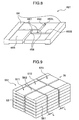
- Fig. 9 is an external perspective view schematically showing only the portion where the plates are laminated as shown in Fig. 3 in a fuel flowing direction, in a plate 561 disposed in the inside of a fuel passageway 551 of the reactor according to the present embodiment.
- Three laminated plates 571, 572, and 573 having the plurality of laminated plates 561 are disposed with a predetermined gap L therebetween in a fuel flowing direction.
- the plate fuel passageway 62 of the fuel entrance becomes non-uniform, thereby causing a case in which in some parts, the fuel does not contact with the medium.
- the uniform plate fuel passageway 62 is ensured in the other laminated plates 571 and 572 less influenced by heat than the laminated plate 573. Accordingly, the fuel passing through a slit 563 of the laminated plate 573 passes through the plate fuel passageway 62 of the laminated plates 571 and 572, thereby preventing deterioration of the reaction efficiency of the reactor 1.
- the slit is formed in a linear shape, but may be formed in a curve shape or a wave shape. Additionally, the number of connection portions formed as bridge in the slit may increase. Likewise, various modifications may be made within a scope not departing from the spirit of the invention that the influence of the heat deformation reduces.
Landscapes
- Engineering & Computer Science (AREA)
- Chemical & Material Sciences (AREA)
- Combustion & Propulsion (AREA)
- Mechanical Engineering (AREA)
- General Engineering & Computer Science (AREA)
- Chemical Kinetics & Catalysis (AREA)
- Hydrogen, Water And Hydrids (AREA)
- Heat-Exchange Devices With Radiators And Conduit Assemblies (AREA)
- Exhaust Gas After Treatment (AREA)
Abstract
Description
- The present invention relates to an engine system. More specifically, the present invention relates to an engine system which employs as a fuel, either hydrogen produced from a hydrogen containing medium in terms of reaction using a catalyst or mixture of the hydrogen and the hydrogen containing medium.
- Since the engine system which employs gasoline as a fuel discharges carbon dioxide, hydrogen has been gaining attention as an alternative fuel for the countermeasure to global warming. However, usage of hydrogen is difficult in that hydrogen is combustible material and is highly explosive. Particularly, a high technique must be required for storing hydrogen in a gas state or a liquid state, and it is also a difficult technique to store hydrogen so from the viewpoint of safety and a large weight of a storage container.
- Therefore, a technique has been developed in which hydrogen is stored while being contained in a hydrogen medium, hydrogen gas is extracted in terms of a chemical reaction at a necessary time, and then the hydrogen gas is supplied to the engine system. However, it is necessary to provide a constant heat source all the time when proceeding chemical reaction due to the fact that the chemical reaction takes place as an endothermic reaction. For example, in an automobile mounting thereon the engine system employing the gasoline as a fuel, when the afore-mentioned engine supplied with the hydrogen gas in terms of the chemical reaction, is mounted to replace the gasoline engine, a certain technique has been proposed in which the exhaust gas from the engine is used as the heat source (see
JP-A-2005-299499 - Such a reactor incorporated in this type of engine system is operated under a high-temperature circumstance due to the exhaust gas from the engine. In some cases, a problem may arise in that the reactor itself is subjected to a thermal deformation due to different heat expansions of the respective parts of the reactor caused by either a combination of materials having different linear expansion coefficients or a difference in local temperature of the reactor. In case of severe deformation, since respective sectional areas of a plurality of fuel flow passageways or exhaust gas flow passage become non-uniform, heat amount supplied from the exhaust gas becomes non-uniform, thereby causing such a problem that reaction efficiency of the reactor is deteriorated as a whole.
- Although there is disclosed a technique of a heat exchanger provided with a heat transfer mechanism which is the same as that of the reactor in various industrial fields, the technique is not based on the particular circumstance as mounted on the above-described automobile. For this reason, in spite of the fact that the engine system needs to be compact in size, it is difficult to avoid an increase in size or a complication of the engine system.
- An object of the invention is to provide an engine system which is able to reduce an influence due to heat deformation of a reactor and in which either hydrogen produced from a hydrogen containing medium in terms of reaction using a catalyst or a mixture of the hydrogen and the hydrogen containing medium is employed as a fuel.
- In order to achieve the above-described object, according to an aspect of the invention, there is provided an engine system in which either hydrogen produced from a hydrogen containing medium in terms of reaction using a catalyst or a mixture of the hydrogen and the hydrogen containing medium is employed as fuel, the engine system including a reactor configured to cause a reaction using the catalyst, wherein the reactor is configured by alternately disposing a plurality exhaust passageways and a plurality of fuel passageways of the engine system with a wall interposed therebetween, wherein at least one carrier configured to carry the catalyst and to be formed in a substantially rectangular plate shape is interposed in the inside of at least one of fuel passageways, and wherein the carrier is provided with a plate portion which has a surface disposed in a fuel flowing direction and is formed in a substantially rectangular plate shape, and at least one slit portion which divides the surface of the plate portion in a fuel flowing direction.
- According to the above-described configuration of the invention, in the engine system in which either hydrogen produced from a hydrogen containing medium in terms of reaction using a catalyst or a mixture of the hydrogen and the hydrogen containing medium is employed as a fuel, since the slit is formed in the carrier of the reactor so as to reduce a variation in heat transmission circumstance in the inside of the reactor, it is possible to reduce an influence of heat deformation on the reactor.
- According to the engine system, since it is possible to reduce the influence of the heat deformation of the reactor, it is possible to restrict deterioration of reaction efficiency of the reactor as a whole.
- Other objects, features and advantages of the invention will become apparent from the following description of the embodiments of the invention taken in conjunction with the accompanying drawings. Brief Description of Several Views of Drawings
-
Fig. 1 is an explanatory and schematic view showing an entire configuration of an engine system according to a first embodiment of the invention. -
Fig. 2 is a cross-sectional view showing a reactor according to the first embodiment of the invention, taken along the line II-II shown inFig. 1 . -
Fig. 3 is an explanatory cross-sectional view showing one section perpendicular to a fuel flowing direction (a direction from the backward side toward the forward side ofFig. 2 ) of one fuel passageway according to the first embodiment of the invention, enlarged only in the vertical direction. -
Fig. 4 is a perspective view showing an example of a plate disposed in a fuel passageway according to the first embodiment of the invention. -
Fig. 5 is a perspective view showing a plate disposed in an inside of a fuel passageway of a reactor according to a second embodiment of the invention. -
Fig. 6 is a perspective view showing a plate disposed in an inside of a fuel passageway of a reactor according to a third embodiment of the invention. -
Fig. 7 is a perspective view showing a plate disposed in an inside of a fuel passageway of a reactor according to a fourth embodiment of the invention. -
Fig. 8 is a perspective view showing a plate disposed in an inside of a fuel passageway of a reactor according to a fifth embodiment of the invention. -
Fig. 9 is an external perspective view schematically showing a plate disposed in an inside of a fuel passageway of a reactor according to a sixth embodiment of the invention. - Hereinafter, a first embodiment of the invention will be described in detail with reference to the accompanying drawings.
Fig. 1 is an explanatory and schematic view showing an entire configuration of an engine system according to the present embodiment. - An
engine system 100 according to the present embodiment includes anengine 10 employing a hydrogen medium as a fuel. Theengine 10 is connected to anintake pipe 11 and anexhaust pipe 12, and a reactor 1 is disposed in a portion of theexhaust pipe 12. - Here, the hydrogen medium indicates all mediums capable of chemically storing and discharging hydrogen, which includes hydrocarbon-based fuel such as gasoline, light oil, kerosene, heavy oil, decaline, cyclohexane, methyl-cyclohexane, naphthalene, benzene, and toluene, mixed fuel thereof, hydrogen peroxide, ammonia, nitrogen, or oxygen. In the below description, the medium chemically storing hydrogen is referred to as "hydrogen medium" and the medium chemically discharging hydrogen is referred to as "dehydrogenation medium".
- The hydrogen medium as a fuel is introduced from a
hydrogen medium tank 14 to a pump 30 (see the arrow F01). Then, the hydrogen medium is pressurized by thepump 30, and is injected into a reactor 1 via a pipe 41 (see the arrow F02). Since the hydrogen medium contacts with a catalyst at a high temperature in the reactor 1, chemical reaction therebetween is promoted. Subsequently, the hydrogen medium is decomposed to produce reaction gas including dehydrogenation medium and hydrogen gas. - The produced gas passes through a pipe 44 (see the arrow F03) and is supplied to a
separator 16. In theseparator 16 provided with a cooler, the produced gas is separated into hydrogen and other dehydrogenation mediums. The separated dehydrogenation mediums pass through a pipe 45 (see the arrow F04) and are stored in adehydrogenation medium tank 15. On the other hand, the separated hydrogen passes through a pipe 46 (see the arrow F05) and is supplied to the inside (not shown) of theengine 10 via theintake pipe 11. The hydrogen combusted in theengine 10 becomes high-temperature exhaust gas. The high-temperature exhaust gas passes through the exhaust pipe 12 (see the arrow F06), is supplied as a heat source to the reactor 1, and then is discharged to the atmosphere via the reactor 1 (see the arrow F07). -
Fig. 2 is a cross sectional view showing the reactor 1 when taken along the line II-II shown in Fig. - 1. A structure of the reactor is formed by a
housing 53 provided with anexhaust passageway 52 and afuel passageway 51 therein which are juxtaposed to each other. Specifically, the reactor 1 has a structure in which theexhaust passage 52 and thefuel passageway 51 having rectangular flow-passage sections are alternately superposed on a wall of thehousing 53 interposed therebetween. According to the reactor 1 with such a configuration, exhaust heat of theengine 10 is transmitted from theexhaust passage 52 to theadjacent fuel passageway 51 with the wall interposed therebetween, and dehydrogenation reaction of the hydrogen medium is promoted in terms of the heat transmission, thereby realizing high-efficient heat exchange and a compact in size of the reactor 1. - Additionally, a reaction speed of the dehydrogenation reaction increases as the temperature increases. Therefore, in the present embodiment, since the outermost flow passageway (the uppermost portion and the downmost portion shown in
Fig. 2 ) is used as theexhaust passage 52, it is possible to prevent the temperature of thefuel passageway 51 from decreasing. With such a configuration, since it is possible to maintain thefuel passageway 51 at a high temperature, it is possible to more realize a compact in size of the reactor. -
Fig. 3 is an explanatory cross sectional view showing a section perpendicular to a fuel flowing direction (a direction from the backward side to the forward side ofFigs. 2 and 3 ) of onefuel passageway 51, which is enlarged only in a vertical direction.Fig. 4 is a perspective view showing an example of an after-mentioned plate disposed in thefuel passageway 51. Additionally, inFig. 4 , in the same manner asFig. 3 , the plate is enlarged in a vertical direction. - As shown in
Fig. 3 , multiple sheets of verythin plates 61 are fitted and inserted into onefuel passageway 51 shown inFig. 2 while being laminated in a passage space. Then, as shown inFig. 4 , eachplate 61 is substantially formed into a rectangular plate shape, and forms a carrier in which afirst plate 64 and asecond plate 65 carry a catalyst. A thickness of thefirst plate 64 is larger than that of thesecond plate 65, and thesecond plate 65 is formed into a recessed plane. Then, as shown inFig. 3 , theadjacent plates plate fuel passageway 62 in such a manner that the surfaces of thefirst plates plate 61 is provided with aslit 63 for dividing the surface of theplate 61 in a fuel flowing direction. In terms of theslit 63, theplate fuel passageways 62 of the laminatedplates 61 communicate with one another. - With such a configuration, even when a part of the plate is deformed by the heat influence and a part of the flow-passage section of the
plate fuel passageway 62 becomes non-uniform, theplate fuel passageway 62 is capable of flowing the fuel on the upstream side and the downstream side of the non-uniform part in terms of theslit 63. In terms of the flow of the fuel, it is possible to more appropriately distribute the hydrogen medium (redistribution) and thus to make the reaction uniform. - For example, even when a part of the
plate fuel passageway 62 is closed by heat deformation, since theslit 63 is provided, a flow passageway capable of avoiding the closed part exists at other parts. Accordingly, since the fuel flows into the flow passageway, it is possible to reduce a non-uniform state of the transmitted heat amount, and thus to restrict deterioration of the reaction efficiency of the reactor 1 as a whole. - Additionally, since the multiple sheets of
plates 61 are fitted into thefuel passageway 51 while being superposed or laminated (seeFig. 3 ) in such a manner that theslits 63 are laminated so that the positions thereof are coincident with each other, even when the flow-passageway section becomes non-uniform or the flow passageway is closed by the heat deformation, it is possible to facilitate the uniform redistribution of the fuel. - Here, since a heat-resisting property needs to be ensured in the
housing 53 and a catalyst carrying function needs to be ensured in theplate 61, in some cases, thehousing 53 and theplate 61 may be formed of different metal materials. In accordance with a combination of different metal materials, theplate 61 may be largely thermal-expanded in a transverse direction (in a horizontal direction ofFig. 3 ) of a surface perpendicular to a fuel flowing direction. In the conventional art, since aplate side surface 61S is restrained in thehousing 53, it is difficult to avoid deformation of theplate 61. However, in the present embodiment, since theslit 63 is provided, the thermal-expanded amount is absorbed, thereby preventing large deformation such as buckling caused by heat expansion. - Since the dehydrogenation reaction is endothermic reaction, sufficient heat needs to be supplied, and hence a heat supply passageway to the reactor 1 is important. A main heat transmission route to the
fuel passageway 51 is configured such that the exhaust heat of the engine is transmitted to thehousing 53, is conducted to theplate 61, and then is transmitted to the plate fuel passageway 62 (fuel passageway 51). In the present embodiment, since a minimum width of theslit 63 is smaller than that of theplate fuel passageway 62, most of hydrogen medium flows through theplate fuel passageway 62. - Additionally, in the present embodiment, since the
slit 63 is formed in the vicinity of the center in a transverse direction of theplate 61, heat is high-efficiently supplied from thehousing 53 located in the outside in a transverse direction ofFig. 3 to theplate side surface 61S, and is supplied from theplate side surface 61S to the center in a transverse direction of theplate 61. Additionally, since the minimum width of theslit 63 is smaller than the thickness of theplate 61, it is possible to increase the surface area of theplate 61. - With such a configuration, since it is possible to increase the area carrying the catalyst necessary for the dehydrogenation reaction, it is possible to realize a compact in size of the reactor 1. Embodiment 2
- Next, the engine system according to a second embodiment of the invention will be described. In the engine system according to the present embodiment, the same reference numerals designate the same or like components as those of the first embodiment (see
Fig. 1 or the like), and the repetitive description thereof will be therefore omitted. The different parts from the first embodiment will be mainly described. -
Fig. 5 is a perspective view showing aplate 161 disposed in the inside (seeFigs. 1 and2 ) of thefuel passageway 51 of the reactor 1 according to the present embodiment. For example, a size of theplate 161 is not more than that of 200 mm X 500 mm X 0.5 mm. A size of the fuel passageway 62 (seeFig. 3 ) formed between thelaminated plates - The present embodiment is different from the first embodiment in that the shape of the
plate 161 shown inFig. 5 is different. That is, in the present embodiment, aright plate 161R and aleft plate 161L shown inFig. 5 are bridge-connected to each other via afirst connection portion 167 and asecond connection portion 168. In other words, thesecond plates 165 divided by theslit 163 are bridge-connected to each other via thefirst connection portion 167 and asecond connection portion 168. With such a configuration, even when the left andright plates - Likewise, since the left and
right plates connection portions plates 161 are integrally formed with each other, it is possible to easily carry out the positioning operation of theplate 161 upon manufacturing the reactor 2, and thus to reduce a manufacture cost and a manufacture time. - For example, when the
second connection portion 168 having a width of 0.2 mm or less is bridge-connected, elastic deformation easily occurs to thereby absorb the expansion of theplate 161. - Next, the engine system according to a third embodiment of the invention will be described. In the engine system according to the present embodiment, the same reference numerals are given to the same components as those of the first embodiment (see
Fig. 1 or the like) or the second embodiment (seeFig. 5 ), and the repetitive description thereof will be omitted. The different parts from the first embodiment and the second embodiment will be mainly described. -
Fig. 6 is a perspective view showing aplate 261 disposed in the inside of thefuel passageway 51 of the reactor 1 according to the present embodiment. - In the present embodiment,
protrusions 266 are formed in asecond plate 265, and the other configurations are the same as those of the second embodiment. It is desirable that a height of eachprotrusion 266 is the same as that of thefirst plate 64 got higher in a stepped shape from thesecond plate 265 or twice higher than that of thefirst plate 64. In case of the same height, it is desirable that theprotrusions 266 are formed in both surfaces of thesecond plate 265. On the other hand, in case of twice height, it is desirable that theprotrusion 266 is formed in one surface. - In the adjacent
laminated plates second plates protrusions second plates protrusion 266 is brought into contact with the opposedsecond plate 265 as well as thefirst plates 64 combined with each other, it is possible to maintain a gap between theadjacent plates protrusion 266 as a support, and thus to prevent the non-uniform state of the fuel passageway. - A shape of the
protrusion 266 may be a semispherical shape, a conical shape, or a pyramid shape, but it is desirable that theprotrusion 266 is formed into a surface-contacting shape such as a cylindrical shape or a prism shape because the contact parts are easily deformed when, due to the heat deformation, theprotrusion 266 is brought into contact with the adjacentlaminated plates 261 or is brought into contact with the housing 53 (seeFig. 3 ) as an outer wall to be slid thereon. It is also desirable that the representative diameter in the case of, for example, thecylindrical projection 266 is not more than 10 mm which depth does not prevent the hydrogen medium from flowing. - Next, the engine system according to a fourth embodiment of the invention will be described. In the engine system according to the present embodiment, the same reference numerals are given to the same components as those of the first embodiment to the third embodiment, and the repetitive description thereof will be omitted. The different parts from the first embodiment to the third embodiment will be mainly described.
-
Fig. 7 is a perspective view showing aplate 361 disposed in the inside of thefuel passageway 51 of the reactor 1 according to the present embodiment. - In the present embodiment, a plurality of
slits 363 is formed in asecond plate 365. Since the plurality ofslits 363 is provided, it is possible to increase the surface area of theplate 361. Since the performance of the reactor 1 is improved by increasing the contact area between the hydrogen medium and theplate 361 carrying the catalyst, it is possible to realize a compact in size of the reactor 1. Even in the present embodiment, like the second embodiment shown inFig. 5 , basically, aright plate 361R and aleft plate 361L are connected to each other via afirst connection portion 367 and asecond connection portion 368. In the example shown inFig. 7 , thesecond connection portion 368 is provided at two positions in a heat transmission direction, but in a case where heat resistance of thesecond connection portion 368 is relatively high, it is possible to facilitate the heat supply by providing thesecond connection portion 368, for example, at three positions or more. - Next, the engine system according to a fifth embodiment of the invention will be described. In the engine system according to the present embodiment, the same reference numerals are given to the same components as those of the first embodiment to the fourth embodiment, and the repetitive description thereof will be omitted. The different parts from the first embodiment to the fourth embodiment will be mainly described.
-
Fig. 8 is a perspective view showing aplate 461 disposed in the inside of thefuel passageway 51 of the reactor 1 according to the present embodiment. - In the present embodiment, a plurality of
slits 463 is formed in theplate 461. Theslit 463 includes alongitudinal slit 463L extending in a flow passageway direction and atransverse slit 463S extending in a direction perpendicular to the flow passageway, which are formed in two directions meeting at right angles. - Then, in the present embodiment, as shown in
Fig. 8 , thelongitudinal slit 463L is formed in a linear shape in a fuel flowing direction at a position slightly deviated from the center point in a transverse direction of a surface meeting at right angles with a fuel flowing direction of theplate 461. Thetransverse slit 463S is formed in a linear shape in a direction meeting at right angles with a fuel flowing direction at a position slightly deviated from the center point in a longitudinal direction of a surface in a fuel flowing direction of theplate 461. Here, theslits 463L and the 463S do not communicate with each other, andconnection portions - Likewise, since the
longitudinal slit 463L and thetransverse slit 463S are provided, it is possible to reduce heat deformation in a flow passageway direction where fuel flows and a direction meeting at right angles with the flow passageway. Additionally, fluid flowing to the fuel passageway 62 (seeFig. 3 ) formed by laminating theplates 461 by using a stepped portion between thefirst plate 64 and thesecond plate 465 passes through a position in the vicinity of any one of the slits 463 (463L and 463S), thereby facilitating the flow of the fluid between the adjacent flow passageways. From this point, since it is possible to make uniform the flow of the fuel between thefuel passageways 62, ..., 62, it is possible to improve the reaction efficiency of the reactor 1. Embodiment 6 - Next, the engine system according to a sixth embodiment of the invention will be described. In the engine system according to the present embodiment, the same reference numerals are given to the same components as those of the first embodiment to the fifth embodiment, and the repetitive description thereof will be omitted. The different parts from the first embodiment to the fifth embodiment will be mainly described.
-
Fig. 9 is an external perspective view schematically showing only the portion where the plates are laminated as shown inFig. 3 in a fuel flowing direction, in aplate 561 disposed in the inside of afuel passageway 551 of the reactor according to the present embodiment. - Three
laminated plates laminated plates 561 are disposed with a predetermined gap L therebetween in a fuel flowing direction. With such a configuration, it is possible to obtain the following advantages. That is, when thelaminated plate 573 corresponding to a fuel entrance (see the arrow IN) is largely deformed by heat, theplate fuel passageway 62 of the fuel entrance (see the arrow IN) becomes non-uniform, thereby causing a case in which in some parts, the fuel does not contact with the medium. Even in this case, the uniformplate fuel passageway 62 is ensured in the otherlaminated plates laminated plate 573. Accordingly, the fuel passing through aslit 563 of thelaminated plate 573 passes through theplate fuel passageway 62 of thelaminated plates - As described above, the preferred embodiments of the invention have been described. The invention is not limited to the description of the drawings, but may be modified within a scope not departing from the spirit of the invention.
- For example, the slit is formed in a linear shape, but may be formed in a curve shape or a wave shape. Additionally, the number of connection portions formed as bridge in the slit may increase. Likewise, various modifications may be made within a scope not departing from the spirit of the invention that the influence of the heat deformation reduces.
- It should be further understood by those skilled in the art that although the foregoing description has been made on embodiments of the invention, the invention is not limited thereto and various changes and modifications may be made without departing from the spirit of the invention and the scope of the appended claims.
Claims (7)
- An engine system (100) in which either hydrogen produced from a hydrogen containing medium in terms of reaction using a catalyst or mixture of the hydrogen and the hydrogen containing medium is employed as a fuel, the engine system (100) comprising a reactor (1) configured to cause a reaction using the catalyst,
wherein said reactor (1) is configured by alternately disposing a plurality exhaust passages (52) and a plurality of fuel passageways (51) of said engine system with a wall interposed therebetween,
wherein at least one carrier (61) configured to carry said catalyst and to be formed in a substantially rectangular plate shape is interposed in an inside of at least one of said fuel passageways (51), and
wherein said carrier (61) is provided with a plate portion (65) which has a surface disposed in a fuel flowing direction and is formed in a substantially rectangular plate shape, and at least one slit portion (63) which divides the surface of said plate portion (65) in said fuel flowing direction. - The engine system (100) according to Claim 1,
wherein at least one connection portion (167) is provided to mutually bridge-connect said divided plate portions opposed to each other with said slit portion (63) interposed therebetween. - The engine system (100) according to Claim 1,
wherein a plurality of protrusions (266) is formed in at least one surface of said plate portions (265). - The engine system (100) according to Claim 1,
wherein said carrier is provided with at least one second slit portion (363) which divides the surface of said plate portion (365) in a direction perpendicular to said fuel flowing direction. - The engine system (100) according to Claim 4,
wherein at least one connection portion (367) is provided between said slit portion (363) and said second slit portion (363) to mutually bridge-connect said divided plate portions (365) opposed to each other. - The engine system (100) according to Claim 1,
wherein a plurality of said carriers (61) is laminated with a predetermined gap (63) therebetween in a direction perpendicular to said fuel flowing direction, and
wherein said slit portions and/or said second slit portions (63, 163, 263, 363, 463, 563) of at least adjacent ones in said carriers are formed at substantially the same position. - The engine system (100) according to Claim 6,
wherein said plurality of the laminated carriers (61, 161, 261, 361, 461, 561) configured to have a plurality of the carriers disposed to be laminated, is arranged with a predetermined gap (63, 163, 263, 363, 463, 563) therebetween in said fuel flowing direction.
Applications Claiming Priority (1)
| Application Number | Priority Date | Filing Date | Title |
|---|---|---|---|
| JP2007309664A JP4990110B2 (en) | 2007-11-30 | 2007-11-30 | Engine system |
Publications (4)
| Publication Number | Publication Date |
|---|---|
| EP2065589A2 true EP2065589A2 (en) | 2009-06-03 |
| EP2065589A8 EP2065589A8 (en) | 2009-08-05 |
| EP2065589A3 EP2065589A3 (en) | 2011-04-20 |
| EP2065589B1 EP2065589B1 (en) | 2012-10-10 |
Family
ID=40404493
Family Applications (1)
| Application Number | Title | Priority Date | Filing Date |
|---|---|---|---|
| EP08020607A Not-in-force EP2065589B1 (en) | 2007-11-30 | 2008-11-27 | Engine system |
Country Status (3)
| Country | Link |
|---|---|
| US (1) | US8171894B2 (en) |
| EP (1) | EP2065589B1 (en) |
| JP (1) | JP4990110B2 (en) |
Families Citing this family (1)
| Publication number | Priority date | Publication date | Assignee | Title |
|---|---|---|---|---|
| WO2011130612A2 (en) * | 2010-04-15 | 2011-10-20 | Thomas Merritt | System and method for the generation of hydrogen fuel product |
Citations (1)
| Publication number | Priority date | Publication date | Assignee | Title |
|---|---|---|---|---|
| JP2005299499A (en) | 2004-04-12 | 2005-10-27 | Toyota Motor Corp | Internal combustion engine using hydrogen |
Family Cites Families (33)
| Publication number | Priority date | Publication date | Assignee | Title |
|---|---|---|---|---|
| US3800768A (en) * | 1972-02-28 | 1974-04-02 | Standard Oil Co | Apparatus and method for fueling an internal combustion engine |
| DE2216196C3 (en) * | 1972-04-04 | 1980-09-04 | Siemens Ag, 1000 Berlin Und 8000 Muenchen | Surface gasifier for gasifying liquid fuel |
| FR2272272B1 (en) * | 1974-05-24 | 1979-05-25 | Peugeot & Renault | |
| US4170200A (en) * | 1974-06-14 | 1979-10-09 | Nippondenso Co., Ltd. | Internal combustion engine with reformed gas generator |
| JPS58138252A (en) | 1982-02-09 | 1983-08-17 | Nissan Motor Co Ltd | Exhaust gas by-pass device of engine using alkohol-modified gas fuel |
| JPS59120773A (en) | 1982-12-27 | 1984-07-12 | Nissan Motor Co Ltd | Safety device of reformed gas engine |
| JPS6062646A (en) | 1983-09-14 | 1985-04-10 | Nissan Motor Co Ltd | Production method of alcohol reformer |
| US4862836A (en) * | 1987-12-15 | 1989-09-05 | Mobil Oil Corporation | Operation of an internal combustion engine with a pre-engine converter |
| JPH0599074A (en) * | 1991-10-07 | 1993-04-20 | Mazda Motor Corp | Hydrogen storage tank |
| JPH06264732A (en) * | 1993-03-11 | 1994-09-20 | Toyota Motor Corp | Catalyst overheat prevention device for exhaust gas purification of internal combustion engine |
| JPH0829088A (en) * | 1994-07-11 | 1996-02-02 | Nisshin Steel Co Ltd | Perforated element of laminate of press-formed metal plates |
| US6257175B1 (en) * | 1997-09-15 | 2001-07-10 | Edward G. Mosher | Oxygen and hydrogen generator apparatus for internal combustion engines |
| JP2002514286A (en) * | 1998-03-26 | 2002-05-14 | プガチェフ・アレクサンドル・ワシリエビッチ | Method and apparatus for preparing a fuel-air mixture for an internal combustion engine and a heat exchanger used in the apparatus |
| DE19927176C1 (en) * | 1999-06-15 | 2000-11-02 | Daimler Chrysler Ag | Fuel supply system for diesel IC engine e.g. for commercial vehicle, has separated liquid fuel fraction supplied to fuel reservoir holding fuel at injection pressure |
| JP4511065B2 (en) * | 2000-06-05 | 2010-07-28 | 日本碍子株式会社 | Honeycomb structure, honeycomb filter, and manufacturing method thereof |
| JP3960035B2 (en) * | 2000-12-28 | 2007-08-15 | 三菱マテリアル株式会社 | Hybrid power system |
| JP2002227657A (en) * | 2001-02-02 | 2002-08-14 | Takeshi Hatanaka | Hydrogen engine, power generation system and vehicle driven thereby |
| CA2415536A1 (en) * | 2002-12-31 | 2004-06-30 | Long Manufacturing Ltd. | Reformer for converting fuel to hydrogen |
| JP4039383B2 (en) * | 2003-10-21 | 2008-01-30 | トヨタ自動車株式会社 | Internal combustion engine using hydrogen |
| JP2005146926A (en) * | 2003-11-12 | 2005-06-09 | Toyota Motor Corp | Fuel reformer |
| JP2005291657A (en) * | 2004-04-02 | 2005-10-20 | Nissan Motor Co Ltd | Heat exchanger and manufacturing method thereof |
| JP4055737B2 (en) * | 2004-04-12 | 2008-03-05 | トヨタ自動車株式会社 | Internal combustion engine system having hydrogen generation function |
| US7401578B2 (en) * | 2004-05-21 | 2008-07-22 | Gemini Energy Technologies, Inc. | System and method for the co-generation of fuel having a closed-loop energy cycle |
| US20090194042A1 (en) * | 2004-07-13 | 2009-08-06 | Workman Alan J | Fuel Supply System for a Vehicle Including a Vaporization Device for Converting Fuel and Water into Hydrogen |
| EP1803922A4 (en) * | 2004-07-28 | 2010-10-06 | Nissan Motor | Fuel supply system |
| JP2006248814A (en) | 2005-03-09 | 2006-09-21 | Hitachi Ltd | Hydrogen supply apparatus and hydrogen supply method |
| US7789047B2 (en) * | 2005-05-24 | 2010-09-07 | Toyota Jidosha Kabushiki Kaisha | Hydrogen-fueled internal combustion engine |
| JP4779721B2 (en) * | 2006-03-10 | 2011-09-28 | 株式会社日立製作所 | Engine system |
| JP4737023B2 (en) | 2006-10-04 | 2011-07-27 | 株式会社日立製作所 | Hydrogen engine system |
| JP2008031931A (en) * | 2006-07-28 | 2008-02-14 | Toyota Motor Corp | Exhaust gas reforming apparatus and exhaust gas reforming system |
| JP5272320B2 (en) * | 2007-03-29 | 2013-08-28 | 株式会社日立製作所 | HYDROGEN SUPPLY DEVICE, ITS MANUFACTURING METHOD, AND DISTRIBUTED POWER SUPPLY AND AUTOMOBILE |
| US7793621B2 (en) * | 2007-10-05 | 2010-09-14 | Realm Industries | Alternative fuel engine |
| US8186315B2 (en) * | 2007-11-02 | 2012-05-29 | Arthur Jeffs | Hydrogen fuel assist device for an internal combustion engine and method |
-
2007
- 2007-11-30 JP JP2007309664A patent/JP4990110B2/en not_active Expired - Fee Related
-
2008
- 2008-11-26 US US12/323,550 patent/US8171894B2/en not_active Expired - Fee Related
- 2008-11-27 EP EP08020607A patent/EP2065589B1/en not_active Not-in-force
Patent Citations (1)
| Publication number | Priority date | Publication date | Assignee | Title |
|---|---|---|---|---|
| JP2005299499A (en) | 2004-04-12 | 2005-10-27 | Toyota Motor Corp | Internal combustion engine using hydrogen |
Also Published As
| Publication number | Publication date |
|---|---|
| US20090139470A1 (en) | 2009-06-04 |
| EP2065589B1 (en) | 2012-10-10 |
| JP4990110B2 (en) | 2012-08-01 |
| JP2009133248A (en) | 2009-06-18 |
| EP2065589A8 (en) | 2009-08-05 |
| EP2065589A3 (en) | 2011-04-20 |
| US8171894B2 (en) | 2012-05-08 |
Similar Documents
| Publication | Publication Date | Title |
|---|---|---|
| US7237602B2 (en) | Heat exchanger | |
| EP2105601B1 (en) | Engine system | |
| US6936364B2 (en) | Method and apparatus for vaporizing fuel for a reformer fuel cell system | |
| KR20070076409A (en) | Method for Exchanging Mass Transfer in a Fuel Deoxygenation System | |
| US8221512B2 (en) | Hydrogen generator and fuel cell system | |
| EP3145017A1 (en) | Fuel cell | |
| AU2003237843A1 (en) | Method and apparatus for vaporizing fuel for a reformer fuel cell system | |
| KR20060007376A (en) | Quick Start Fuel Reforming System and Technology | |
| JP2006172924A (en) | Fuel cell separator | |
| EP2065589B1 (en) | Engine system | |
| US20230275311A1 (en) | Battery pack and battery case | |
| JP2010251329A (en) | Fuel cell | |
| JP2003262489A (en) | Plate heat exchanger | |
| EP4254604A1 (en) | Cooling plate arrangement, battery system, electric vehicle and method for assembling | |
| JP5082312B2 (en) | Fuel cell separator structure | |
| US10794337B2 (en) | EGR cooler | |
| WO2006007216A1 (en) | Multi-pass heat exchanger | |
| JP3843509B2 (en) | Plate reactor | |
| US8152872B2 (en) | Modular reformer with enhanced heat recuperation | |
| KR102146101B1 (en) | Printed circuit heat exchanger and heat exchanging device comprising it | |
| JP6242143B2 (en) | Combined heat exchange and fluid mixing device | |
| KR102899810B1 (en) | Heat exchanger with freeze protection | |
| KR102899825B1 (en) | Heat exchanger with freeze protection | |
| JP2024065463A (en) | Battery cooling heat sink | |
| JP2008147135A (en) | Fuel cell |
Legal Events
| Date | Code | Title | Description |
|---|---|---|---|
| PUAI | Public reference made under article 153(3) epc to a published international application that has entered the european phase |
Free format text: ORIGINAL CODE: 0009012 |
|
| 17P | Request for examination filed |
Effective date: 20081127 |
|
| AK | Designated contracting states |
Kind code of ref document: A2 Designated state(s): AT BE BG CH CY CZ DE DK EE ES FI FR GB GR HR HU IE IS IT LI LT LU LV MC MT NL NO PL PT RO SE SI SK TR |
|
| AX | Request for extension of the european patent |
Extension state: AL BA MK RS |
|
| RIN1 | Information on inventor provided before grant (corrected) |
Inventor name: SANO, TADASHI Inventor name: ISHIKAWA, TAKAO Inventor name: SHIMADA, ATSUSHI Inventor name: TOGASHI, SHIGENORI Inventor name: SOUMA, KENICHI |
|
| PUAL | Search report despatched |
Free format text: ORIGINAL CODE: 0009013 |
|
| AK | Designated contracting states |
Kind code of ref document: A3 Designated state(s): AT BE BG CH CY CZ DE DK EE ES FI FR GB GR HR HU IE IS IT LI LT LU LV MC MT NL NO PL PT RO SE SI SK TR |
|
| AX | Request for extension of the european patent |
Extension state: AL BA MK RS |
|
| 17Q | First examination report despatched |
Effective date: 20110510 |
|
| AKX | Designation fees paid |
Designated state(s): AT BE BG CH CY CZ DE DK EE ES FI FR GB GR HR HU IE IS IT LI LT LU LV MC MT NL NO PL PT RO SE SI SK TR |
|
| GRAP | Despatch of communication of intention to grant a patent |
Free format text: ORIGINAL CODE: EPIDOSNIGR1 |
|
| GRAS | Grant fee paid |
Free format text: ORIGINAL CODE: EPIDOSNIGR3 |
|
| GRAA | (expected) grant |
Free format text: ORIGINAL CODE: 0009210 |
|
| AK | Designated contracting states |
Kind code of ref document: B1 Designated state(s): AT BE BG CH CY CZ DE DK EE ES FI FR GB GR HR HU IE IS IT LI LT LU LV MC MT NL NO PL PT RO SE SI SK TR |
|
| REG | Reference to a national code |
Ref country code: GB Ref legal event code: FG4D |
|
| REG | Reference to a national code |
Ref country code: AT Ref legal event code: REF Ref document number: 579093 Country of ref document: AT Kind code of ref document: T Effective date: 20121015 Ref country code: CH Ref legal event code: EP |
|
| REG | Reference to a national code |
Ref country code: IE Ref legal event code: FG4D |
|
| REG | Reference to a national code |
Ref country code: DE Ref legal event code: R096 Ref document number: 602008019234 Country of ref document: DE Effective date: 20121206 |
|
| PG25 | Lapsed in a contracting state [announced via postgrant information from national office to epo] |
Ref country code: SI Free format text: LAPSE BECAUSE OF FAILURE TO SUBMIT A TRANSLATION OF THE DESCRIPTION OR TO PAY THE FEE WITHIN THE PRESCRIBED TIME-LIMIT Effective date: 20121010 |
|
| REG | Reference to a national code |
Ref country code: NL Ref legal event code: VDEP Effective date: 20121010 |
|
| REG | Reference to a national code |
Ref country code: AT Ref legal event code: MK05 Ref document number: 579093 Country of ref document: AT Kind code of ref document: T Effective date: 20121010 |
|
| REG | Reference to a national code |
Ref country code: LT Ref legal event code: MG4D |
|
| PG25 | Lapsed in a contracting state [announced via postgrant information from national office to epo] |
Ref country code: NO Free format text: LAPSE BECAUSE OF FAILURE TO SUBMIT A TRANSLATION OF THE DESCRIPTION OR TO PAY THE FEE WITHIN THE PRESCRIBED TIME-LIMIT Effective date: 20130110 Ref country code: IS Free format text: LAPSE BECAUSE OF FAILURE TO SUBMIT A TRANSLATION OF THE DESCRIPTION OR TO PAY THE FEE WITHIN THE PRESCRIBED TIME-LIMIT Effective date: 20130210 Ref country code: ES Free format text: LAPSE BECAUSE OF FAILURE TO SUBMIT A TRANSLATION OF THE DESCRIPTION OR TO PAY THE FEE WITHIN THE PRESCRIBED TIME-LIMIT Effective date: 20130121 Ref country code: FI Free format text: LAPSE BECAUSE OF FAILURE TO SUBMIT A TRANSLATION OF THE DESCRIPTION OR TO PAY THE FEE WITHIN THE PRESCRIBED TIME-LIMIT Effective date: 20121010 Ref country code: NL Free format text: LAPSE BECAUSE OF FAILURE TO SUBMIT A TRANSLATION OF THE DESCRIPTION OR TO PAY THE FEE WITHIN THE PRESCRIBED TIME-LIMIT Effective date: 20121010 Ref country code: LT Free format text: LAPSE BECAUSE OF FAILURE TO SUBMIT A TRANSLATION OF THE DESCRIPTION OR TO PAY THE FEE WITHIN THE PRESCRIBED TIME-LIMIT Effective date: 20121010 Ref country code: SE Free format text: LAPSE BECAUSE OF FAILURE TO SUBMIT A TRANSLATION OF THE DESCRIPTION OR TO PAY THE FEE WITHIN THE PRESCRIBED TIME-LIMIT Effective date: 20121010 Ref country code: HR Free format text: LAPSE BECAUSE OF FAILURE TO SUBMIT A TRANSLATION OF THE DESCRIPTION OR TO PAY THE FEE WITHIN THE PRESCRIBED TIME-LIMIT Effective date: 20121010 |
|
| PG25 | Lapsed in a contracting state [announced via postgrant information from national office to epo] |
Ref country code: PL Free format text: LAPSE BECAUSE OF FAILURE TO SUBMIT A TRANSLATION OF THE DESCRIPTION OR TO PAY THE FEE WITHIN THE PRESCRIBED TIME-LIMIT Effective date: 20121010 Ref country code: CY Free format text: LAPSE BECAUSE OF FAILURE TO SUBMIT A TRANSLATION OF THE DESCRIPTION OR TO PAY THE FEE WITHIN THE PRESCRIBED TIME-LIMIT Effective date: 20121010 Ref country code: GR Free format text: LAPSE BECAUSE OF FAILURE TO SUBMIT A TRANSLATION OF THE DESCRIPTION OR TO PAY THE FEE WITHIN THE PRESCRIBED TIME-LIMIT Effective date: 20130111 Ref country code: BE Free format text: LAPSE BECAUSE OF FAILURE TO SUBMIT A TRANSLATION OF THE DESCRIPTION OR TO PAY THE FEE WITHIN THE PRESCRIBED TIME-LIMIT Effective date: 20121010 Ref country code: PT Free format text: LAPSE BECAUSE OF FAILURE TO SUBMIT A TRANSLATION OF THE DESCRIPTION OR TO PAY THE FEE WITHIN THE PRESCRIBED TIME-LIMIT Effective date: 20130211 Ref country code: LV Free format text: LAPSE BECAUSE OF FAILURE TO SUBMIT A TRANSLATION OF THE DESCRIPTION OR TO PAY THE FEE WITHIN THE PRESCRIBED TIME-LIMIT Effective date: 20121010 |
|
| PG25 | Lapsed in a contracting state [announced via postgrant information from national office to epo] |
Ref country code: AT Free format text: LAPSE BECAUSE OF FAILURE TO SUBMIT A TRANSLATION OF THE DESCRIPTION OR TO PAY THE FEE WITHIN THE PRESCRIBED TIME-LIMIT Effective date: 20121010 |
|
| REG | Reference to a national code |
Ref country code: CH Ref legal event code: PL |
|
| PG25 | Lapsed in a contracting state [announced via postgrant information from national office to epo] |
Ref country code: DK Free format text: LAPSE BECAUSE OF FAILURE TO SUBMIT A TRANSLATION OF THE DESCRIPTION OR TO PAY THE FEE WITHIN THE PRESCRIBED TIME-LIMIT Effective date: 20121010 Ref country code: CZ Free format text: LAPSE BECAUSE OF FAILURE TO SUBMIT A TRANSLATION OF THE DESCRIPTION OR TO PAY THE FEE WITHIN THE PRESCRIBED TIME-LIMIT Effective date: 20121010 Ref country code: SK Free format text: LAPSE BECAUSE OF FAILURE TO SUBMIT A TRANSLATION OF THE DESCRIPTION OR TO PAY THE FEE WITHIN THE PRESCRIBED TIME-LIMIT Effective date: 20121010 Ref country code: CH Free format text: LAPSE BECAUSE OF NON-PAYMENT OF DUE FEES Effective date: 20121130 Ref country code: BG Free format text: LAPSE BECAUSE OF FAILURE TO SUBMIT A TRANSLATION OF THE DESCRIPTION OR TO PAY THE FEE WITHIN THE PRESCRIBED TIME-LIMIT Effective date: 20130110 Ref country code: LI Free format text: LAPSE BECAUSE OF NON-PAYMENT OF DUE FEES Effective date: 20121130 Ref country code: EE Free format text: LAPSE BECAUSE OF FAILURE TO SUBMIT A TRANSLATION OF THE DESCRIPTION OR TO PAY THE FEE WITHIN THE PRESCRIBED TIME-LIMIT Effective date: 20121010 |
|
| PLBE | No opposition filed within time limit |
Free format text: ORIGINAL CODE: 0009261 |
|
| STAA | Information on the status of an ep patent application or granted ep patent |
Free format text: STATUS: NO OPPOSITION FILED WITHIN TIME LIMIT |
|
| REG | Reference to a national code |
Ref country code: IE Ref legal event code: MM4A |
|
| PG25 | Lapsed in a contracting state [announced via postgrant information from national office to epo] |
Ref country code: IT Free format text: LAPSE BECAUSE OF FAILURE TO SUBMIT A TRANSLATION OF THE DESCRIPTION OR TO PAY THE FEE WITHIN THE PRESCRIBED TIME-LIMIT Effective date: 20121010 Ref country code: RO Free format text: LAPSE BECAUSE OF FAILURE TO SUBMIT A TRANSLATION OF THE DESCRIPTION OR TO PAY THE FEE WITHIN THE PRESCRIBED TIME-LIMIT Effective date: 20121010 |
|
| 26N | No opposition filed |
Effective date: 20130711 |
|
| GBPC | Gb: european patent ceased through non-payment of renewal fee |
Effective date: 20130110 |
|
| PG25 | Lapsed in a contracting state [announced via postgrant information from national office to epo] |
Ref country code: IE Free format text: LAPSE BECAUSE OF NON-PAYMENT OF DUE FEES Effective date: 20121127 |
|
| REG | Reference to a national code |
Ref country code: DE Ref legal event code: R097 Ref document number: 602008019234 Country of ref document: DE Effective date: 20130711 |
|
| PG25 | Lapsed in a contracting state [announced via postgrant information from national office to epo] |
Ref country code: GB Free format text: LAPSE BECAUSE OF NON-PAYMENT OF DUE FEES Effective date: 20130110 Ref country code: MT Free format text: LAPSE BECAUSE OF FAILURE TO SUBMIT A TRANSLATION OF THE DESCRIPTION OR TO PAY THE FEE WITHIN THE PRESCRIBED TIME-LIMIT Effective date: 20121010 |
|
| PG25 | Lapsed in a contracting state [announced via postgrant information from national office to epo] |
Ref country code: TR Free format text: LAPSE BECAUSE OF FAILURE TO SUBMIT A TRANSLATION OF THE DESCRIPTION OR TO PAY THE FEE WITHIN THE PRESCRIBED TIME-LIMIT Effective date: 20121010 Ref country code: MC Free format text: LAPSE BECAUSE OF NON-PAYMENT OF DUE FEES Effective date: 20121130 |
|
| PG25 | Lapsed in a contracting state [announced via postgrant information from national office to epo] |
Ref country code: LU Free format text: LAPSE BECAUSE OF NON-PAYMENT OF DUE FEES Effective date: 20121127 |
|
| PG25 | Lapsed in a contracting state [announced via postgrant information from national office to epo] |
Ref country code: HU Free format text: LAPSE BECAUSE OF FAILURE TO SUBMIT A TRANSLATION OF THE DESCRIPTION OR TO PAY THE FEE WITHIN THE PRESCRIBED TIME-LIMIT Effective date: 20081127 |
|
| REG | Reference to a national code |
Ref country code: FR Ref legal event code: PLFP Year of fee payment: 8 |
|
| PGFP | Annual fee paid to national office [announced via postgrant information from national office to epo] |
Ref country code: DE Payment date: 20151125 Year of fee payment: 8 |
|
| PGFP | Annual fee paid to national office [announced via postgrant information from national office to epo] |
Ref country code: FR Payment date: 20151008 Year of fee payment: 8 |
|
| REG | Reference to a national code |
Ref country code: DE Ref legal event code: R119 Ref document number: 602008019234 Country of ref document: DE |
|
| REG | Reference to a national code |
Ref country code: FR Ref legal event code: ST Effective date: 20170731 |
|
| PG25 | Lapsed in a contracting state [announced via postgrant information from national office to epo] |
Ref country code: FR Free format text: LAPSE BECAUSE OF NON-PAYMENT OF DUE FEES Effective date: 20161130 |
|
| PG25 | Lapsed in a contracting state [announced via postgrant information from national office to epo] |
Ref country code: DE Free format text: LAPSE BECAUSE OF NON-PAYMENT OF DUE FEES Effective date: 20170601 |