JP2005299499A - Internal combustion engine using hydrogen - Google Patents
Internal combustion engine using hydrogen Download PDFInfo
- Publication number
- JP2005299499A JP2005299499A JP2004116606A JP2004116606A JP2005299499A JP 2005299499 A JP2005299499 A JP 2005299499A JP 2004116606 A JP2004116606 A JP 2004116606A JP 2004116606 A JP2004116606 A JP 2004116606A JP 2005299499 A JP2005299499 A JP 2005299499A
- Authority
- JP
- Japan
- Prior art keywords
- hydrogen
- catalyst
- fuel
- combustion engine
- internal combustion
- Prior art date
- Legal status (The legal status is an assumption and is not a legal conclusion. Google has not performed a legal analysis and makes no representation as to the accuracy of the status listed.)
- Withdrawn
Links
Images


Classifications
-
- Y—GENERAL TAGGING OF NEW TECHNOLOGICAL DEVELOPMENTS; GENERAL TAGGING OF CROSS-SECTIONAL TECHNOLOGIES SPANNING OVER SEVERAL SECTIONS OF THE IPC; TECHNICAL SUBJECTS COVERED BY FORMER USPC CROSS-REFERENCE ART COLLECTIONS [XRACs] AND DIGESTS
- Y02—TECHNOLOGIES OR APPLICATIONS FOR MITIGATION OR ADAPTATION AGAINST CLIMATE CHANGE
- Y02T—CLIMATE CHANGE MITIGATION TECHNOLOGIES RELATED TO TRANSPORTATION
- Y02T10/00—Road transport of goods or passengers
- Y02T10/10—Internal combustion engine [ICE] based vehicles
- Y02T10/30—Use of alternative fuels, e.g. biofuels
Landscapes
- Output Control And Ontrol Of Special Type Engine (AREA)
- Combined Controls Of Internal Combustion Engines (AREA)
- Hydrogen, Water And Hydrids (AREA)
Abstract
Description
この発明は、水素利用内燃機関に関する。 The present invention relates to a hydrogen-utilizing internal combustion engine.
従来、例えば特開2003−343360号公報に開示されるように、水素生成機能を有する内燃機関のシステムが知られている。このシステムは、具体的には、デカリン等の有機ハイドライドを含む水素化燃料を原料として、水素リッチガスと、ナフタレン等の脱水素生成物とを生成する機構、並びに、生成された水素リッチガスを燃料として作動する水素エンジンを備えている。 Conventionally, as disclosed in, for example, Japanese Patent Application Laid-Open No. 2003-343360, an internal combustion engine system having a hydrogen generation function is known. Specifically, this system uses a hydrogenated fuel containing an organic hydride such as decalin as a raw material to generate a hydrogen rich gas and a dehydrogenated product such as naphthalene, and the generated hydrogen rich gas as a fuel. It has a working hydrogen engine.
上記公報に開示されるシステムは、水素エンジンの作動中に、その作動に伴って発生する熱を利用して、水素化燃料を水素リッチガスと脱水素生成物に分離する。より具体的には、水素化燃料を触媒上に噴射し、触媒上で脱水素化反応を起こさせて水素を取り出している。この際、水素を効率良く取り出すために、触媒をエンジンの廃熱を用いて加熱している。 The system disclosed in the above publication separates hydrogenated fuel into a hydrogen-rich gas and a dehydrogenated product using heat generated during the operation of the hydrogen engine. More specifically, hydrogenated fuel is injected onto the catalyst, and a dehydrogenation reaction is caused on the catalyst to take out hydrogen. At this time, in order to efficiently extract hydrogen, the catalyst is heated using the waste heat of the engine.
エンジンの廃熱を用いて触媒を加熱する方法として、エンジンの排気ガスのエネルギーを用いて触媒を加熱することが考えられる。しかしながら、排気ガスのエネルギーを用いて触媒を加熱して水素を取り出す場合に、排気熱を有効に利用できないとエンジンが要求する水素量に対して取り出した水素量が不足してしまう場合がある。 As a method of heating the catalyst using the waste heat of the engine, it is conceivable to heat the catalyst using the energy of the exhaust gas of the engine. However, when hydrogen is extracted by heating the catalyst using the energy of the exhaust gas, if the exhaust heat cannot be used effectively, the amount of hydrogen extracted with respect to the amount of hydrogen required by the engine may be insufficient.
また、排気ガスの熱により触媒を加熱する場合、触媒を排気管に導入する必要がある。このため、排気管と触媒を含む構造が複雑となり、製造コストが増大するという問題が生じる。 Further, when the catalyst is heated by the heat of the exhaust gas, it is necessary to introduce the catalyst into the exhaust pipe. For this reason, the structure including the exhaust pipe and the catalyst becomes complicated, resulting in a problem that the manufacturing cost increases.
この発明は、上述のような課題を解決するためになされたもので、排気ガスのエネルギーを用いて脱水素化反応を起こす際に、反応効率を向上させて水素の生成量を増大させるとともに、脱水素化反応を生じさせる機構を簡素に構成して製造を容易とすることを目的とする。 The present invention has been made to solve the above-described problems, and when performing a dehydrogenation reaction using the energy of exhaust gas, the reaction efficiency is improved and the amount of hydrogen generated is increased. An object is to facilitate the production by simply configuring the mechanism for causing the dehydrogenation reaction.
第1の発明は、上記の目的を達成するため、内燃機関の排気通路の内部に導入され、端部が前記排気通路の外に配置されたケーシングと、前記ケーシングの内部に設けられた触媒と、前記ケーシングの前記端部に設けられ、前記触媒に向けて有機ハイドライド含有燃料を供給する燃料供給手段と、前記触媒上での脱水素反応により前記有機ハイドライド含有燃料から取り出された水素を内燃機関に供給する水素供給手段と、を備えたことを特徴とする。 In order to achieve the above object, a first invention is a casing introduced into an exhaust passage of an internal combustion engine and having an end disposed outside the exhaust passage, and a catalyst provided in the casing. A fuel supply means for supplying an organic hydride-containing fuel toward the catalyst provided at the end of the casing; and hydrogen extracted from the organic hydride-containing fuel by a dehydrogenation reaction on the catalyst. And hydrogen supply means for supplying to the battery.
第2の発明は、第1の発明において、前記ケーシングが前記排気通路の長手方向に延在するように設けられたことを特徴とする。 According to a second invention, in the first invention, the casing is provided so as to extend in a longitudinal direction of the exhaust passage.
第3の発明は、第1の発明において、前記ケーシングが前記排気通路と直交する方向に延在するように設けられたことを特徴とする。 According to a third aspect, in the first aspect, the casing is provided so as to extend in a direction orthogonal to the exhaust passage.
第4の発明は、第1〜第3の発明のいずれかにおいて、前記ケーシングの両側の前記端部が前記排気通路の外に配置され、前記燃料供給手段は、前記ケーシングの両側の前記端部に設けられたことを特徴とする。 According to a fourth invention, in any one of the first to third inventions, the end portions on both sides of the casing are disposed outside the exhaust passage, and the fuel supply means includes the end portions on both sides of the casing. It is characterized by being provided in.
第5の発明は、第4の発明において、前記内燃機関が必要とする水素量が所定のしきい値以上のときは、前記ケーシングの両側の前記端部に設けられた前記燃料供給手段から前記触媒に向けて有機ハイドライド含有燃料を供給することを特徴とする。 According to a fifth invention, in the fourth invention, when the amount of hydrogen required by the internal combustion engine is equal to or greater than a predetermined threshold, the fuel supply means provided at the end portions on both sides of the casing An organic hydride-containing fuel is supplied to the catalyst.
第6の発明は、第4の発明において、前記内燃機関が必要とする水素量が所定のしきい値未満のときは、前記ケーシングの一方の前記端部に設けられた前記燃料供給手段から前記触媒に向けて有機ハイドライド含有燃料を供給することを特徴とする。 According to a sixth invention, in the fourth invention, when the amount of hydrogen required by the internal combustion engine is less than a predetermined threshold, the fuel supply means provided at one end of the casing An organic hydride-containing fuel is supplied to the catalyst.
第7の発明は、第6の発明において、所定の場合に、有機ハイドライド含有燃料を供給する前記燃料供給手段を、一方の前記燃料供給手段から他方の前記燃料供給手段へ切り換えることを特徴とする。 According to a seventh invention, in the sixth invention, the fuel supply means for supplying the organic hydride-containing fuel is switched from one fuel supply means to the other fuel supply means in a predetermined case. .
第8の発明は、第6の発明において、前記燃料供給手段の前記触媒側の先端温度を検出する手段を備え、有機ハイドライド含有燃料を供給していない前記燃料供給手段の前記先端温度が所定値以上となった場合に、前記燃料供給手段の切り換えを行うことを特徴とする。 According to an eighth invention, in the sixth invention, there is provided means for detecting the tip temperature on the catalyst side of the fuel supply means, and the tip temperature of the fuel supply means not supplying the organic hydride-containing fuel is a predetermined value. In this case, the fuel supply means is switched.
第9の発明は、第6の発明において、前記触媒の温度を検出する手段を備え、有機ハイドライド含有燃料を供給している側の前記触媒の温度が所定値以下となった場合に、前記燃料供給手段の切り換えを行うことを特徴とする。 According to a ninth invention, in the sixth invention, there is provided means for detecting the temperature of the catalyst, and when the temperature of the catalyst on the side supplying the organic hydride-containing fuel becomes a predetermined value or less, the fuel The supply means is switched.
第10の発明は、第6の発明において、所定時間間隔毎に前記燃料供給手段の切り換えを行うことを特徴とする。 According to a tenth aspect, in the sixth aspect, the fuel supply means is switched at predetermined time intervals.
第11の発明は、第5〜第10の発明のいずれかにおいて、前記所定のしきい値は、前記ケーシングの一方の前記端部に設けられた前記燃料供給手段からの有機ハイドライド含有燃料の供給によって前記有機ハイドライド含有燃料から取り出すことのできる最大の水素量であることを特徴とする。 According to an eleventh aspect of the present invention, in any one of the fifth to tenth aspects, the predetermined threshold is the supply of the organic hydride-containing fuel from the fuel supply means provided at one end of the casing. The maximum amount of hydrogen that can be extracted from the organic hydride-containing fuel.
第1の発明によれば、触媒が内部に設けられたケーシングを排気通路の内部に導入したため、触媒の周囲を排気ガスで囲むことができ、排気ガスの熱を触媒に十分に与えることが可能となる。従って、触媒の温度を高温に維持することができ、脱水素反応の効率を向上させることが可能となる。また、ケーシングの端部を排気通路の外に配置し、燃料供給手段をケーシングの端部に設けたため、排気通路に燃料供給手段を貫通させる必要がなくなり、排気通路の内部の触媒に向けて有機ハイドライド含有燃料を供給する構造を容易に製造することができる。更に、触媒の周囲が排気ガスで囲まれる2層構造としたため、脱水素反応を生じさせる構造を簡素かつ小型に構成することができ、生産性を高めるとともにシステムへの搭載性を良好にすることができる。 According to the first invention, since the casing in which the catalyst is provided is introduced into the exhaust passage, the catalyst can be surrounded by the exhaust gas, and the heat of the exhaust gas can be sufficiently applied to the catalyst. It becomes. Therefore, the temperature of the catalyst can be maintained at a high temperature, and the efficiency of the dehydrogenation reaction can be improved. Further, since the end of the casing is disposed outside the exhaust passage and the fuel supply means is provided at the end of the casing, there is no need to penetrate the fuel supply means through the exhaust passage, and the organic material is directed toward the catalyst inside the exhaust passage. A structure for supplying hydride-containing fuel can be easily manufactured. Furthermore, since the catalyst is surrounded by exhaust gas in a two-layer structure, the structure for generating a dehydrogenation reaction can be made simple and compact, improving productivity and improving the mounting capability in the system. Can do.
第2の発明によれば、ケーシングを排気通路の長手方向に延在するように設けたため、排気ガスの流れ方向とケーシングの長手方向を一致させることができ、触媒の表面積を最大限に拡大することができる。従って、触媒の利用効率を高めることができ、脱水素反応の反応量を増大させることができる。 According to the second invention, since the casing is provided so as to extend in the longitudinal direction of the exhaust passage, the flow direction of the exhaust gas and the longitudinal direction of the casing can be matched, and the surface area of the catalyst is maximized. be able to. Therefore, the utilization efficiency of the catalyst can be increased and the reaction amount of the dehydrogenation reaction can be increased.
第3の発明によれば、ケーシングを排気通路と直交する方向に延在するように設けたため、ケーシングの内部に設けられた触媒に均一に排気ガスの熱を伝えることができ、排気ガスから触媒への熱交換効率を高めることが可能となる。 According to the third aspect of the invention, since the casing is provided so as to extend in a direction orthogonal to the exhaust passage, the heat of the exhaust gas can be uniformly transmitted to the catalyst provided in the casing, and from the exhaust gas to the catalyst It is possible to increase the efficiency of heat exchange with.
第4の発明によれば、ケーシングの両側の端部に燃料供給手段を設けたため、ケーシングの内部に設けられた触媒の全域に有機ハイドライド含有燃料を供給することが可能となる。従って、脱水素反応の効率を向上させることが可能となり、反応量を増大させることが可能となる。 According to the fourth invention, since the fuel supply means is provided at both ends of the casing, the organic hydride-containing fuel can be supplied to the entire area of the catalyst provided inside the casing. Therefore, the efficiency of the dehydrogenation reaction can be improved, and the reaction amount can be increased.
第5の発明によれば、内燃機関が必要とする水素量が所定のしきい値以上のときは、ケーシングの両側の端部に設けられた燃料供給手段から有機ハイドライド含有燃料を供給するため、触媒の全域で脱水素反応を生じさせることができ、必要水素量に応じた多量の水素を生成することが可能となる。 According to the fifth invention, when the amount of hydrogen required by the internal combustion engine is equal to or greater than a predetermined threshold value, the organic hydride-containing fuel is supplied from the fuel supply means provided at both ends of the casing. A dehydrogenation reaction can be caused in the entire area of the catalyst, and a large amount of hydrogen corresponding to the required amount of hydrogen can be generated.
第6の発明によれば、内燃機関が必要とする水素量が所定のしきい値未満のときは、ケーシングの一方の端部に設けられた燃料供給手段から触媒に向けて有機ハイドライド含有燃料を供給するため、一方の燃料供給手段のみの作動によって必要水素量に応じた量の水素を生成することが可能となる。 According to the sixth invention, when the amount of hydrogen required by the internal combustion engine is less than a predetermined threshold value, the organic hydride-containing fuel is supplied from the fuel supply means provided at one end of the casing toward the catalyst. In order to supply, it becomes possible to produce | generate the quantity of hydrogen according to the amount of required hydrogen by the action | operation of only one fuel supply means.
第7の発明によれば、所定の場合に、有機ハイドライド含有燃料を供給する燃料供給手段を、一方の燃料供給手段から他方の燃料供給手段へ切り換えるため、脱水素反応の吸熱作用に起因して触媒の温度が低下した場合であっても、燃料が供給されている側の触媒の温度は常に高温状態に保たれる。これにより、脱水素反応の効率を高めることが可能となる。 According to the seventh invention, the fuel supply means for supplying the organic hydride-containing fuel is switched from one fuel supply means to the other fuel supply means in a predetermined case, resulting in the endothermic action of the dehydrogenation reaction. Even when the temperature of the catalyst is lowered, the temperature of the catalyst on the side where the fuel is supplied is always kept at a high temperature. Thereby, the efficiency of the dehydrogenation reaction can be increased.
第8の発明によれば、有機ハイドライド含有燃料を供給していない燃料供給手段の先端温度が所定値以上となった場合に、有機ハイドライド含有燃料を供給する燃料供給手段を切り換えるため、先端温度が所定値以上となった燃料供給手段からの燃料供給によって、先端温度を低下させることができる。従って、燃料供給手段の先端温度が過度に上昇してしまうことを抑えることができる。 According to the eighth aspect of the invention, when the tip temperature of the fuel supply means that is not supplying the organic hydride-containing fuel becomes equal to or higher than a predetermined value, the tip temperature is changed to switch the fuel supply means that supplies the organic hydride-containing fuel. The tip temperature can be lowered by supplying fuel from the fuel supply means that has reached a predetermined value or more. Accordingly, it is possible to prevent the tip temperature of the fuel supply means from rising excessively.
第9の発明によれば、有機ハイドライド含有燃料を供給している側の触媒の温度が所定値以下となった場合に、有機ハイドライド含有燃料を供給する燃料供給手段を切り換えるため、脱水素反応の吸熱作用に起因して触媒の温度が低下した場合であっても、燃料が供給されている側の触媒の温度は常に高温状態に保たれることになる。これにより、脱水素反応の効率を高めることが可能となる。 According to the ninth aspect of the present invention, when the temperature of the catalyst on the side supplying the organic hydride-containing fuel becomes equal to or lower than a predetermined value, the fuel supply means for supplying the organic hydride-containing fuel is switched. Even when the temperature of the catalyst is lowered due to the endothermic action, the temperature of the catalyst on the side where the fuel is supplied is always kept at a high temperature. Thereby, the efficiency of the dehydrogenation reaction can be increased.
第10の発明によれば、所定時間間隔毎に有機ハイドライド含有燃料を供給する燃料供給手段を切り換えることで、脱水素反応の吸熱作用に起因して触媒の温度が低下した場合であっても、燃料が供給されている側の触媒の温度は高温状態に維持することができる。これにより、脱水素反応の効率を高めることが可能となる。 According to the tenth invention, even when the temperature of the catalyst is lowered due to the endothermic action of the dehydrogenation reaction by switching the fuel supply means for supplying the organic hydride-containing fuel at predetermined time intervals, The temperature of the catalyst on the side where the fuel is supplied can be maintained at a high temperature. Thereby, the efficiency of the dehydrogenation reaction can be increased.
第11の発明によれば、所定のしきい値を、ケーシングの一方の端部に設けられた燃料供給手段からの有機ハイドライド含有燃料の供給によって有機ハイドライド含有燃料から取り出すことのできる最大の水素量としたことで、内燃機関が必要とする水素量が所定のしきい値以上のときはケーシングの両側の端部に設けられた燃料供給手段の両方から燃料を供給することで必要水素量を満足することができ、内燃機関が必要とする水素量が所定のしきい値未満のときは燃料供給手段の一方から燃料を供給することで必要水素量を満足することができる。 According to the eleventh invention, the predetermined threshold value is the maximum amount of hydrogen that can be taken out from the organic hydride-containing fuel by supplying the organic hydride-containing fuel from the fuel supply means provided at one end of the casing. Therefore, when the amount of hydrogen required by the internal combustion engine exceeds a predetermined threshold value, the required amount of hydrogen is satisfied by supplying fuel from both fuel supply means provided at both ends of the casing. When the amount of hydrogen required by the internal combustion engine is less than a predetermined threshold value, the required amount of hydrogen can be satisfied by supplying fuel from one of the fuel supply means.
以下、図面に基づいてこの発明の一実施形態について説明する。尚、各図において共通する要素には、同一の符号を付して重複する説明を省略する。なお、以下の実施の形態によりこの発明が限定されるものではない。 An embodiment of the present invention will be described below with reference to the drawings. In addition, the same code | symbol is attached | subjected to the element which is common in each figure, and the overlapping description is abbreviate | omitted. The present invention is not limited to the following embodiments.
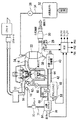
図1は、本発明の各実施形態に係る内燃機関システムの構成を説明するための図である。このシステムは、内燃機関10を備えている。内燃機関10には、吸気管12および排気管14が連通している。
FIG. 1 is a diagram for explaining a configuration of an internal combustion engine system according to each embodiment of the present invention. This system includes an internal combustion engine 10. An
吸気管12には、吸入空気量を制御するためのスロットルバルブ16が組み込まれている。スロットルバルブ16の下流には、水素供給用インジェクタ18が配置されている。また、内燃機関10の吸気ポートには、ガソリン供給用インジェクタ20が配置されている。
A
水素供給用インジェクタ18には、後述するように、所定の圧力で水素リッチガスが供給されている。水素供給用インジェクタ18は、外部から供給される駆動信号を受けて開弁することにより、その開弁の時間に応じた量の水素リッチガスを吸気管12の内部に噴射することができる。図1に示すシステムでは、水素供給用インジェクタ18を吸気管12に配置することとしているが、その配置はこれに限定されるものではない。すなわち、水素供給用インジェクタ18は、筒内に水素が噴射できるように内燃機関10の本体に組み込んでも良い。
A hydrogen rich gas is supplied to the
ガソリン供給用インジェクタ20には、後述するように、所定の圧力でガソリンが供給されている。ガソリン供給用インジェクタ20は、外部から供給される駆動信号を受けて開弁することにより、その開弁の時間に応じた量のガソリンを吸気ポート内に噴射することができる。
As will be described later, gasoline is supplied to the
排気管14には、脱水素反応器22が装着されている。また、脱水素反応器22の上部には、水素化ガソリンインジェクタ24が組み付けられている。
A
水素化ガソリンインジェクタ24は、後述するように、所定の圧力で水素化ガソリンの供給を受けており、外部から供給される駆動信号を受けて開弁することにより、その開弁の時間に応じた量の水素化ガソリンを脱水素反応器22の内部に供給することができる。ここで、内燃機関10が必要とする水素量は、内燃機関10の運転状態に応じて変動する。ECU80は、内燃機関10が必要とする水素量と、運転状態(機関回転数、負荷(スロットル開度))との関係を定めたマップを記憶しており、このマップから必要水素量を求め、水素化ガソリンインジェクタ24の開弁・閉弁状態を制御する。また、脱水素反応器22は、排気管14から放射される排気熱を利用して、上記の如く供給される水素化ガソリンを水素リッチガスと脱水素化ガソリンとに分離し、それらを流出させる機能を有している。
As will be described later, the
排気管14には、脱水素反応器22の上流において、排気温度センサ25が組み込まれている。また、排気管14には、脱水素反応器22の下流において、O2センサ26およびNOxセンサ28が組み込まれている。O2センサ26は、排気ガス中の酸素の有無を基礎として、排気空燃比に応じた出力を発するセンサである。また、NOxセンサ28は、排気ガス中のNOx濃度に応じた出力を発するセンサである。これらのセンサ26,28の下流には、排気ガスを浄化するための触媒30が配置されている。
An exhaust temperature sensor 25 is incorporated in the
本実施形態のシステムは、水素化ガソリンタンク32を備えている。水素化ガソリンタンク32の中には、一般的なガソリンに比して有機ハイドライドを多量に含む水素化ガソリンが貯留される。ここで、「有機ハイドライド」とは、300℃程度の温度で脱水素反応を起こす炭化水素(HC)成分であり、具体的には、デカリンやシクロヘキサンがこれに該当する。
The system of this embodiment includes a
通常のガソリン(LFT−1C)には、トルエンが40%程度含まれている。トルエンを水素化すると、有機ハイドライドであるメチルシクロヘキサン(C7H14)を生成することができる。つまり、通常のガソリンを原料として、その中に含まれるトルエンを水素化すると、メチルシクロヘキサンを40%程度含有する水素化ガソリンを生成することができる。本実施形態では、便宜上、水素化ガソリンタンク32には、このような組成を有する水素化ガソリンが給油されるものとする。
Ordinary gasoline (LFT-1C) contains about 40% of toluene. When toluene is hydrogenated, methylcyclohexane (C 7 H 14 ), which is an organic hydride, can be produced. That is, hydrogenation gasoline containing about 40% of methylcyclohexane can be produced by hydrogenating toluene contained in ordinary gasoline as a raw material. In the present embodiment, for the sake of convenience, the
水素化ガソリンタンク32には、水素化ガソリン供給管34が連通している。水素化ガソリン供給管34は、その途中にポンプ36を備え、その端部において水素化ガソリンインジェクタ24に連通している。水素化ガソリンタンク32内の水素化ガソリンは、内燃機関の運転中に、ポンプ36により汲み上げられて、所定の圧力で水素化ガソリンインジェクタ24に供給される。
A hydrogenated
水素化ガソリンインジェクタ24は、上述した通り、脱水素反応器22の上部に組み付けられている。脱水素反応器22は、排気熱を利用して水素化ガソリンを処理するための装置である。このため、内燃機関の運転中は、脱水素反応器22の内部は、300℃を超える温度に上昇する。
The
水素化ガソリンインジェクタ24は、その内部温度に直接晒されるのを避けるべく、脱水素反応器22の上方空間に主要部分が突出するように組み付けられている。このため、本実施形態のシステムによれば、水素化ガソリンインジェクタ24の温度が、不当に高温となることはない。
The
尚、図1に示すシステムでは、水素化ガソリンインジェクタ24を空冷することとしているが、その冷却の手法はこれに限定されるものではない。例えば、内燃機関10の冷却水を水素化ガソリンインジェクタ24の周囲に導くための冷却水通路を設けて、水素化ガソリンインジェクタ24を水冷することとしても良い。
In the system shown in FIG. 1, the
脱水素反応器22の内部には、反応室が形成されている。水素化ガソリンインジェクタ24から噴射された燃料は、その反応室の内部で水素リッチガスと脱水素化ガソリンとに分離され、脱水素反応器22に接続された管路38に導かれる。脱水素反応器22には管路38を介して分離装置40が連通している。
A reaction chamber is formed inside the
既述した通り、本実施形態において用いられる水素化ガソリンは、通常のガソリンに含まれているトルエンを、有機ハイドライド化したものである。従って、その水素化ガソリンに脱水素処理を施せば、その結果生成されるのは、水素リッチガスと通常のガソリンである。具体的には、有機ハイドライドであるメチルシクロヘキサンC7H14は、脱水素反応により、下記の通り水素H2とトルエンC7H8に分離される。
C7H14→C7H8+3H2 ・・・(1)
(1)式で示される脱水素反応は吸熱反応である。
As described above, the hydrogenated gasoline used in the present embodiment is obtained by organically hydrating toluene contained in normal gasoline. Therefore, if the hydrogenated gasoline is subjected to a dehydrogenation treatment, hydrogen-rich gas and ordinary gasoline are generated as a result. Specifically, methylcyclohexane C 7 H 14 which is an organic hydride is separated into hydrogen H 2 and toluene C 7 H 8 as follows by a dehydrogenation reaction.
C 7 H 14 → C 7 H 8 + 3H 2 (1)
The dehydrogenation reaction represented by the formula (1) is an endothermic reaction.
このため、脱水素反応器22から分離装置40へは、具体的には、水素リッチガスと、通常のガソリンとの混合物が供給されることになる。
For this reason, specifically, a mixture of hydrogen-rich gas and ordinary gasoline is supplied from the
分離装置40は、脱水素反応器22から供給される高温の水素リッチガスおよび脱水素化ガソリン(通常のガソリン)を冷却して、それらを分離する機能を有している。分離装置40は、内燃機関10と同様に冷却水の循環により水冷されている。このため、分離装置40は、効率良く水素リッチガス及び脱水素化ガソリンを冷却することができる。
The
分離装置40の底部には、冷却されることにより液化した脱水素化ガソリンを貯留しておくための液体貯留スペースが設けられている。また、その貯留スペースの上方には、気体のまま残存する水素リッチガスを貯留するための気体貯留スペースが確保されている。分離装置40には、液体貯留スペースに連通するようにガソリン管路42が連通していると共に、気体貯留スペースに連通するように水素管路44が連通している。
A liquid storage space for storing dehydrogenated gasoline liquefied by being cooled is provided at the bottom of the
ガソリン管路42は、ガソリンバッファタンク48に連通している。図1には、水素化ガソリンタンク32とガソリンバッファタンク48とが離れた位置に配置された構成が示されているが、その構成はこれに限定されるものではない。すなわち、それらは、単一の筐体に収めることとしてもよい。
The
ガソリンバッファタンク48には、液量センサ58が組み付けられている。液量センサ58は、その内部に貯留されている脱水素化ガソリンの液量に応じた出力を発するセンサである。また、ガソリンバッファタンク48には、ガソリン供給管60が連通している。ガソリン供給管60は、その途中にポンプ62を備え、その端部においてガソリン供給用インジェクタ20に連通している。ガソリンバッファタンク48内の脱水素化ガソリンは、内燃機関の運転中に、ポンプ62により汲み上げられて、所定の圧力でガソリン供給用インジェクタ20に供給される。
A
水素管路44は、水素バッファタンク64に連通している。また、水素管路44には、分離装置40内の水素リッチガスを水素バッファタンク64に圧送するためのポンプ66と、ポンプ66の吐出側圧力が過大となるのを防ぐためのリリーフ弁68が組み込まれている。ポンプ66およびリリーフ弁68によれば、水素バッファタンク64内に、その内圧が過剰とならない範囲で水素リッチガスを送り込むことができる。
The
水素バッファタンク64には、圧力センサ70が組み付けられている。圧力センサ70は、水素バッファタンク64の内圧に応じた出力を発するセンサである。圧力センサ70の出力によれば、水素バッファタンク64内に貯留されている水素リッチガスの量を推定することができる。
A
水素バッファタンク64には、水素供給管71が連通している。水素供給管71は、その途中にレギュレータ73を備え、その端部において水素供給用インジェクタ18に連通している。このような構成によれば、水素供給用インジェクタ18には、水素バッファタンク64に水素リッチガスが貯留されていることを条件に、レギュレータ73により調整される圧力により水素リッチガスが供給される。
A
本実施形態のシステムは、ECU80を備えている。ECU80は、本実施形態のシステムを制御する機能を有している。すなわち、ECU80には、上述したO2センサ26、NOxセンサ28、液量センサ58および圧力センサ70などの各種センサの出力が供給されている。また、ECU80には、上述したポンプ36,62,66、並びにインジェクタ18,20,24などのアクチュエータが接続されている。ECU80は、それらのセンサ出力を基礎として所定の処理を行うことにより、上述した各種のアクチュエータを適当に駆動することができる。
The system of this embodiment includes an
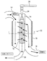
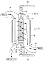
次に、図2及び図3に基づいて、脱水素反応器22の構成を詳細に説明する。図2は、脱水素反応器22の構成を示す断面図である。図2に示すように、脱水素反応を生じさせるための触媒72はケーシング74内に設けられ、ケーシング74は排気ガスの流れ方向にその長手方向を向けた状態で排気管14内に挿入されている。ケーシング74の両端部は排気管14の外に突出しており、上端には水素化ガソリンインジェクタ24が設けられている。また、ケーシング74が挿入された領域の排気管14の外周には、断熱材76が巻き付けられている。このように、排気ガスの流れ方向とケーシング74の長手方向を一致させることで、排気管14の径の拡大を最小限に抑えた状態で、触媒72の容積(表面積)を最大限に拡大することができる。従って、触媒72の利用効率を高めることができる。
Next, based on FIG.2 and FIG.3, the structure of the
図3は、図2の一点鎖線I−I’に沿った断面を示す断面図である。図3に示すように、ケーシング74は排気管14内の中心に配置されており、水素化ガソリンが供給される領域の外側に排気ガスが流れる領域が配置された2層構造が構成されている。従って、排気管14内において、ケーシング74は外側を流れる排気ガスによって囲まれることになり、触媒72への熱供給を効率良く行うことが可能となる。
FIG. 3 is a cross-sectional view showing a cross section taken along the alternate long and short dash line I-I ′ of FIG. 2. As shown in FIG. 3, the
これにより、排気熱の利用効率を大幅に高めることができ、触媒72における脱水素反応を促進することができる。上述したように脱水素反応は吸熱反応であるため、反応量が増えるに従って触媒72の温度が低下し、反応効率が低下してしまうが、本実施形態の構成によれば、反応量が多い場合であっても触媒72の内部温度の低下を最小限に抑えることが可能となる。これにより、大量の水素を常に安定して生成することができる。また、ケーシング74が挿入された領域において排気管14に断熱材76を巻いているため、排気熱が外部に漏れることを最小限に抑えることができ、排気熱の利用効率をより高めることができる。
Thereby, the utilization efficiency of exhaust heat can be significantly increased, and the dehydrogenation reaction in the
また、ケーシング74の端部を排気管14の外側に突出させたため、端部に水素化ガソリンインジェクタ24を装着するだけで触媒72に燃料を供給することが可能となる。これにより、触媒72に燃料を供給するための開口を排気管14自体に設ける必要がなくなり、簡素な構成で触媒72に燃料を供給することが可能となる。従って、脱水素反応器22の生産性を高めることが可能となる。また、脱水素反応器22を2層構造にしたため、3層以上の構造と比較すると径を縮小することができ、システムへの搭載性を高めることが可能となる。また、脱水素反応器22を2層構造にしたため、製造を容易に行うことが可能となる。
Further, since the end portion of the
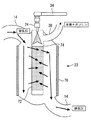
図4は、実施の形態1の他の構成を示す模式図である。図4の例では、管路38をケーシング74の上部に設けている。ケーシング74内では、脱水素反応により水素リッチガスと通常のガソリンが生成され、ケーシング74内での生成量が多くなると水素リッチガスとガソリンは順次に管路38から排出される。従って、ケーシング74と管路38が接続される位置は特に限定されるものではなく、図4に示すようにケーシング74の上部に管路38を接続することも可能である。
FIG. 4 is a schematic diagram showing another configuration of the first embodiment. In the example of FIG. 4, the
以上説明したように実施の形態1によれば、触媒72を内包したケーシング74を排気管14内に挿入し、ケーシング74を高温の排気ガスで囲むようにしたため、排気熱の利用効率を高めることが可能となる。これにより、触媒72への熱供給の効率を高めることができ、触媒72の温度の低下を抑制することができるため、触媒72における脱水素反応の効率を高めることが可能となる。従って、大量の水素を常に安定して生成することができる。また、ケーシング74の端部を排気管14の外に配置したため、ケーシング74の端部から触媒72へ燃料を容易に供給することが可能となる。
As described above, according to the first embodiment, the
実施の形態2.
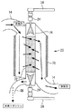
次に、この発明の実施の形態2について説明する。図5は実施の形態2に係る脱水素反応器22を示す断面図である。実施の形態1と同様に、触媒72を内包するケーシング74は排気管14内に挿入されている。
Next, a second embodiment of the present invention will be described. FIG. 5 is a sectional view showing the
図5に示すように、実施の形態2では、触媒72へ水素化ガソリンを噴射する水素化ガソリンインジェクタ24を、ケーシング74の上下2ヶ所に設けている。そして、触媒72に向けて上下から燃料を噴射するようにしている。
As shown in FIG. 5, in the second embodiment,
これにより、触媒72の全域に確実に燃料を供給することが可能となり、触媒72の全体を脱水素反応に活用することができる。従って、水素の生成量を大幅に増加させることが可能となる。
As a result, fuel can be reliably supplied to the entire area of the
ところで、実施の形態1で説明したように、内燃機関が必要とする水素量は、機関の運転状態(回転数、負荷)に応じて変動し、水素化ガソリンインジェクタ24からの燃料噴射量を制御することで水素の生成量が制御される。これに加えて、実施の形態2では水素化ガソリンインジェクタ24を2つ設けているため、必要水素量を上下の水素化ガソリンインジェクタ24で吹き分けることで水素の生成量を制御することが可能である。
By the way, as explained in the first embodiment, the amount of hydrogen required by the internal combustion engine varies depending on the operating state (rotation speed, load) of the engine and controls the fuel injection amount from the
すなわち、実施の形態2では、内燃機関10が必要とする水素量が少ない場合は、一方の水素化ガソリンインジェクタ24のみから燃料を噴射するようにしている。この際、ケーシング74の上部が排気の上流側になるため、より高温の排気熱を受けることができる。従って、一方の水素化ガソリンインジェクタ24のみから燃料を噴射する場合は、上側の水素化ガソリンインジェクタ24から燃料を噴射することで、触媒72の温度を高温に維持することができる。これにより、反応効率を高めることが可能となる。
That is, in the second embodiment, when the amount of hydrogen required by the internal combustion engine 10 is small, fuel is injected from only one
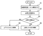
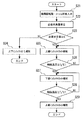
図6は、実施の形態2の水素利用内燃機関における処理の手順を示すフローチャートである。先ず、ステップS1では、機関回転数とスロットル開度を取得する。次のステップS2では、ステップS1で取得した機関回転数とスロットル開度に基づいて、現在の運転状態で必要とされる水素量をマップから算出する。 FIG. 6 is a flowchart showing a processing procedure in the hydrogen-utilizing internal combustion engine of the second embodiment. First, in step S1, the engine speed and the throttle opening are acquired. In the next step S2, the amount of hydrogen required in the current operating state is calculated from the map based on the engine speed and throttle opening acquired in step S1.
次のステップS3では、ステップS2で求めた必要水素量が所定のしきい値以上であるか否かを判定する。ここでは、1本の水素化ガソリンインジェクタ24による燃料噴射で生成可能な限界水素量をAリットル/minとし、必要水素量≧Aであるか否かを判定する。
In the next step S3, it is determined whether or not the necessary hydrogen amount obtained in step S2 is equal to or greater than a predetermined threshold value. Here, the limit hydrogen amount that can be generated by fuel injection by one
ステップS3で必要水素量≧Aの場合は、1本の水素化ガソリンインジェクタ24からの燃料噴射で生成できる限界水素量よりも、現在の運転状態で必要とされる水素量が多いため、ステップS4へ進み、上下の水素化ガソリンインジェクタ24から水素化ガソリンを噴射する。
If the required hydrogen amount ≥A in step S3, the amount of hydrogen required in the current operating state is larger than the limit hydrogen amount that can be generated by fuel injection from one
一方、ステップS3で水素量<Aの場合は、1本の水素化ガソリンインジェクタ24からの燃料噴射で生成できる限界水素量よりも必要水素量が少ないため、ステップS5へ進み、上側の水素化ガソリンインジェクタ24のみから水素化ガソリンを噴射する。
On the other hand, if the hydrogen amount <A in step S3, the required hydrogen amount is less than the limit hydrogen amount that can be generated by fuel injection from one
以上説明したように実施の形態2によれば、ケーシング74の上下に水素化ガソリンインジェクタ24を装着し、上下の水素化ガソリンインジェクタ24から水素化ガソリンを噴射するようにしたため、触媒72の全体を脱水素反応に活用することが可能となる。これにより、水素の生成量を大幅に増大させることが可能となる。
As described above, according to the second embodiment, the
実施の形態3.
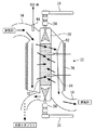
次に、この発明の実施の形態3について説明する。図7は実施の形態3に係る脱水素反応器22を示す断面図である。実施の形態3では、実施の形態2と同様にケーシング74の上下に水素化ガソリンインジェクタ24を設けている。そして、上下の水素化ガソリンインジェクタ24の噴射口近傍に、水素化ガソリンインジェクタ24の先端温度を検出する温度センサ78をそれぞれ設けている。温度センサ78はECU80に接続されている。
Next, a third embodiment of the present invention will be described. FIG. 7 is a cross-sectional view showing the
一方の水素化ガソリンインジェクタ24から水素化ガソリンを噴射した場合、燃料を噴射している水素化ガソリンインジェクタ24は燃料によって冷却されるが、燃料を噴射していない水素化ガソリンインジェクタ24の温度は排気熱によって上昇する。
When hydrogenated gasoline is injected from one
このとき、水素化ガソリンインジェクタ24の先端の温度が過度に上昇すると、水素化ガソリンインジェクタ24の噴射口近傍に残存する燃料が固着し、燃料の噴射に影響を及ぼす場合がある。このため、実施の形態3では、一方の水素化ガソリンインジェクタ24から燃料を噴射している場合に、燃料を噴射していない他方の水素化ガソリンインジェクタ24の先端の温度が所定の温度よりも高くなった場合は、一方の水素化ガソリンインジェクタ24からの燃料噴射を停止し、先端温度が上昇した他方の水素化ガソリンインジェクタ24から燃料を噴射する。
At this time, if the temperature of the tip of the
これにより、先端温度が上昇した水素化ガソリンインジェクタ24を噴射燃料によって冷却することができ、水素化ガソリンインジェクタ24が過度に加熱してしまうことを抑止できる。
Thereby, the
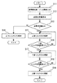
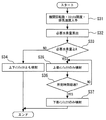
図8は、実施の形態3の水素利用内燃機関における処理の手順を示すフローチャートである。先ず、ステップS11では、機関回転数とスロットル開度を取得する。次のステップS12では、ステップS11で取得した機関回転数とスロットル開度に基づいて、現在の運転状態で必要とされる水素量をマップから算出する。 FIG. 8 is a flowchart showing a processing procedure in the hydrogen-utilizing internal combustion engine of the third embodiment. First, in step S11, the engine speed and the throttle opening are acquired. In the next step S12, the amount of hydrogen required in the current operating state is calculated from the map based on the engine speed and throttle opening acquired in step S11.
次のステップS13では、ステップS12で求めた必要水素量が所定のしきい値以上であるか否かを判定する。ここでは、1本の水素化ガソリンインジェクタ24による燃料噴射で生成可能な限界水素量をAリットル/minとし、必要水素量≧Aであるか否かを判定する。
In the next step S13, it is determined whether or not the required hydrogen amount obtained in step S12 is greater than or equal to a predetermined threshold value. Here, the limit hydrogen amount that can be generated by fuel injection by one
ステップS13で水素量≧Aの場合は、1本の水素化ガソリンインジェクタ24からの燃料噴射で生成できる限界水素量よりも、現在の運転状態で必要とされる水素量が多いため、ステップS14へ進み、上下の水素化ガソリンインジェクタ24から水素化ガソリンを噴射する。ステップS14の後は処理を終了する。
If the amount of hydrogen is greater than or equal to A in step S13, the amount of hydrogen required in the current operating state is larger than the limit amount of hydrogen that can be generated by fuel injection from one
一方、ステップS13で水素量<Aの場合は、1本の水素化ガソリンインジェクタ24からの燃料噴射で生成できる限界水素量よりも必要水素量が少ないため、ステップS15へ進み、上側の水素化ガソリンインジェクタ24のみから水素化ガソリンを噴射する。
On the other hand, if the hydrogen amount <A in step S13, the required hydrogen amount is smaller than the limit hydrogen amount that can be generated by fuel injection from one
ステップS15の後はステップS16へ進み、温度センサ78により燃料を噴射していない下側の水素化ガソリンインジェクタ24の先端温度を検出し、先端温度≧T1℃であるか否かを判定する。ここで、T1℃は、水素化ガソリンインジェクタ24の先端温度の上限値となるしきい値である。ステップS16で先端温度≧T℃の場合は、ステップS17へ進み、下側の水素化ガソリンインジェクタ24のみから燃料を噴射する。一方、ステップS16で先端温度<T℃の場合は、ステップS15へ戻り、上側の水素化ガソリンインジェクタ24のみによる燃料噴射を継続する。
After step S15, the process proceeds to step S16, where the
ステップS17の後はステップS18へ進み、温度センサ78により燃料を噴射していない上側の水素化ガソリンインジェクタ24の先端温度を検出し、先端温度≧T℃であるか否かを判定する。ステップS18で先端温度≧T℃の場合は、ステップS19へ進み、上側の水素化ガソリンインジェクタ24のみから燃料を噴射し、処理を終了する。一方、ステップS18で先端温度<T℃の場合は、ステップS17へ戻り、下側の水素化ガソリンインジェクタ24のみによる燃料噴射を継続する。
After step S17, the process proceeds to step S18, where the tip temperature of the upper
以上説明したように実施の形態3によれば、一方の水素化ガソリンインジェクタ24から燃料を噴射している場合に、燃料を噴射していない他方の水素化ガソリンインジェクタ24の温度が所定の温度よりも高くなった場合は、他方の水素化ガソリンインジェクタ24から燃料を噴射するようにしたため、排気熱によって温度が上昇した水素化ガソリンインジェクタ24を噴射燃料によって冷却することが可能となる。これにより、水素化ガソリンインジェクタ24が過度に加熱してしまうことを抑止できる。
As described above, according to the third embodiment, when fuel is injected from one
実施の形態4.
次に、この発明の実施の形態4について説明する。図9は実施の形態4に係る脱水素反応器22を示す断面図である。図9に示すように、実施の形態4では、触媒72の温度を検出するため、触媒温度センサ82が設けられている。触媒温度センサ82は触媒72の上部と下部にそれぞれ設けられている。また、ケーシング74が挿入された領域の上流には、排気ガスの温度を検出する排気ガス温度センサ84が設けられている。触媒温度センサ82、排気ガス温度センサ84はそれぞれECU80に接続されている。
Next, a fourth embodiment of the present invention will be described. FIG. 9 is a sectional view showing a
実施の形態4では、実施の形態2と同様に、内燃機関10が必要とする水素量に応じて、上下の水素化ガソリンインジェクタ24から水素化ガソリンを噴射する。この際、脱水素反応は吸熱反応であるため、水素を生成すると触媒72の温度が低下する。そして、触媒72の温度が著しく低下した状態では、脱水素反応の効率が低下する。
In the fourth embodiment, as in the second embodiment, hydrogenated gasoline is injected from the upper and lower
上側の水素化ガソリンインジェクタ24から燃料を噴射した場合、脱水素反応は主として触媒72の上部で生じ、触媒72の上部の温度が次第に低下していく。一方、触媒72の下部の温度は排気熱によって高温に維持される。同様に、下側の水素化ガソリンインジェクタ24から燃料を噴射した場合、触媒72の下部の温度は次第に低下するが、触媒72の上部の温度は排気熱によって高温に維持される。
When fuel is injected from the upper
このため、実施の形態4では、内燃機関10が必要とする水素量が比較的少なく、一方の水素化ガソリンインジェクタ24のみから水素化ガソリンを噴射している場合に、触媒温度センサ82によって燃料が噴射されている側の触媒72の温度を検出する。そして、検出値が所定の温度よりも低下した場合は、燃料噴射を停止し、反対側の水素化ガソリンインジェクタ24から燃料を噴射する。これにより、高温状態の触媒72に燃料を噴射することができ、脱水素反応の反応効率を高めることができる。
Therefore, in the fourth embodiment, when the amount of hydrogen required by the internal combustion engine 10 is relatively small and hydrogenated gasoline is injected from only one
このように、燃料が噴射されている側の触媒72の温度が低下した場合は、燃料噴射を反対側の水素化ガソリンインジェクタ24に切り換えることで、常に高温状態の触媒72に向けて燃料を噴射することが可能となる。従って、脱水素反応の反応効率を高めることができ、安定して水素を供給することが可能となる。
As described above, when the temperature of the
図10は、実施の形態4の水素利用内燃機関における処理の手順を示すフローチャートである。先ず、ステップS21では、機関回転数とスロットル開度を取得する。次のステップS22では、ステップS21で取得した機関回転数とスロットル開度に基づいて、現在の運転状態で必要とされる水素量をマップから算出する。 FIG. 10 is a flowchart showing a processing procedure in the hydrogen-utilizing internal combustion engine of the fourth embodiment. First, in step S21, the engine speed and the throttle opening are acquired. In the next step S22, the amount of hydrogen required in the current operating state is calculated from the map based on the engine speed and throttle opening obtained in step S21.
次のステップS23では、ステップS22で求めた必要水素量が所定のしきい値以上であるか否かを判定する。ここでは、1本の水素化ガソリンインジェクタ24による燃料噴射で生成可能な限界水素量をAリットル/minとし、必要水素量≧Aであるか否かを判定する。
In the next step S23, it is determined whether or not the required hydrogen amount obtained in step S22 is greater than or equal to a predetermined threshold value. Here, the limit hydrogen amount that can be generated by fuel injection by one
ステップS23で必要水素量≧Aの場合は、1本の水素化ガソリンインジェクタ24からの燃料噴射で生成できる限界水素量よりも、現在の運転状態で必要とされる水素量が多いため、ステップS24へ進み、上下の水素化ガソリンインジェクタ24から水素化ガソリンを噴射する。ステップS24の後は処理を終了する。
If the required hydrogen amount ≧ A in step S23, the amount of hydrogen required in the current operating state is larger than the limit hydrogen amount that can be generated by fuel injection from one
一方、ステップS23で必要水素量<Aの場合は、1本の水素化ガソリンインジェクタ24からの燃料噴射で生成できる限界水素量よりも必要水素量が少ないため、ステップS25へ進み、上側の水素化ガソリンインジェクタ24のみから水素化ガソリンを噴射する。
On the other hand, if the required hydrogen amount <A in step S23, the required hydrogen amount is smaller than the limit hydrogen amount that can be generated by fuel injection from one
ステップS25の後はステップS26へ進み、触媒72の上部に設けられた触媒温度センサ82により、触媒72の上部の温度を検出し、触媒温度≧T2℃であるか否かを判定する。ここで、T2℃は、触媒72の温度の下限値となるしきい値である。ステップS26で触媒温度≧T2℃の場合はステップS27へ進み、燃料噴射を下側の水素化ガソリンインジェクタ24に切り換えて、下側の水素化ガソリンインジェクタ24のみから燃料を噴射する。一方、ステップS26で先端温度<T2℃の場合は、ステップS25へ戻り、上側の水素化ガソリンインジェクタ24のみによる燃料噴射を継続する。
After step S25, the process proceeds to step S26, where the temperature of the upper part of the
ステップS27の後はステップS28へ進み、触媒72の上部に設けられた触媒温度センサ82により、触媒72の下部の温度を検出し、触媒温度≧T2℃であるか否かを判定する。ステップS28で触媒温度≧T℃の場合はステップS29へ進み、燃料噴射を上側の水素化ガソリンインジェクタ24に切り換えて、上側の水素化ガソリンインジェクタ24のみから燃料を噴射する。一方、ステップS28で触媒温度<T2℃の場合は、ステップS27へ戻り、下側の水素化ガソリンインジェクタ24のみによる燃料噴射を継続する。
After step S27, the process proceeds to step S28, where the temperature of the lower part of the
図10の処理では、触媒温度センサ82の検出値に基づいて燃料を噴射する水素化ガソリンインジェクタ24を切り換えているが、脱水素反応による触媒72の温度の低下の度合いは、排気温度、水素化ガソリンインジェクタ24からの燃料噴射量などと相関があるため、これらのパラメータに基づいて燃料を噴射する水素化ガソリンインジェクタ24を切り換えるようにしても良い。例えば、上下の水素化ガソリンインジェクタ24を切り換える周期と排気温度との関係を定めた2次元マップ、若しくは、上下の水素化ガソリンインジェクタ24を切り換える周期、排気温度、および水素化ガソリンインジェクタ24による燃料噴射量の関係を定めた3次元マップを作成しておき、排気温度センサ84の検出値、水素化ガソリンインジェクタ24からの燃料噴射量をこれらのマップに当てはめて水素化ガソリンインジェクタ24の切換周期を求めるようにする。
In the process of FIG. 10, the
以上説明したように実施の形態4によれば、触媒72の温度、または排気温度に基づいて燃料を噴射する水素化ガソリンインジェクタ24を切り換えるようにしたため、脱水素反応に伴って触媒72の温度が低下してしまうことを抑止することができ、安定して水素を生成することが可能となる。
As described above, according to the fourth embodiment, since the
実施の形態5.
次に、この発明の実施の形態5について説明する。実施の形態5は、実施の形態2と同様に燃料を噴射する上下の水素化ガソリンインジェクタ24を切り換える場合において、所定の時間間隔で切り換えを行うものである。
Embodiment 5 FIG.
Next, a fifth embodiment of the present invention will be described. In the fifth embodiment, when the upper and lower
図11は、実施の形態5の水素利用内燃機関における処理の手順を示すフローチャートである。先ず、ステップS31では、機関回転数とスロットル開度を取得する。次のステップS32では、ステップS31で取得した機関回転数とスロットル開度に基づいて、現在の運転状態で必要とされる水素量をマップから算出する。 FIG. 11 is a flowchart showing a processing procedure in the hydrogen-utilizing internal combustion engine of the fifth embodiment. First, in step S31, the engine speed and the throttle opening are acquired. In the next step S32, the amount of hydrogen required in the current operating state is calculated from the map based on the engine speed and throttle opening acquired in step S31.
次のステップS33では、ステップS32で求めた必要水素量が所定のしきい値以上であるか否かを判定する。ここでは、1本の水素化ガソリンインジェクタ24による燃料噴射で生成可能な限界水素量をAリットル/minとし、必要水素量≧Aであるか否かを判定する。
In the next step S33, it is determined whether or not the required hydrogen amount obtained in step S32 is greater than or equal to a predetermined threshold value. Here, the limit hydrogen amount that can be generated by fuel injection by one
ステップS33で必要水素量≧Aの場合は、1本の水素化ガソリンインジェクタ24からの燃料噴射で生成できる限界水素量よりも、現在の運転状態で必要とされる水素量が多いため、ステップS34へ進み、上下の水素化ガソリンインジェクタ24から水素化ガソリンを噴射する。ステップS34の後は処理を終了する。
If the required hydrogen amount ≧ A in step S33, the amount of hydrogen required in the current operating state is larger than the limit hydrogen amount that can be generated by fuel injection from one
一方、ステップS33で必要水素量<Aの場合は、1本の水素化ガソリンインジェクタ24からの燃料噴射で生成できる限界水素量よりも必要水素量が少ないため、ステップS35へ進み、上側の水素化ガソリンインジェクタ24のみから水素化ガソリンを噴射する。
On the other hand, if the required hydrogen amount <A in step S33, the required hydrogen amount is smaller than the limit hydrogen amount that can be generated by fuel injection from one
次のステップS36では、所定時間が経過したか否かを判定する。所定時間が経過した場合は、ステップS37へ進み、燃料噴射を下側の水素化ガソリンインジェクタ24に切り換え、下側の水素化ガソリンインジェクタ24のみから水素化ガソリンを噴射する。ここで、所定時間は排気温度に応じて変動するしきい値であって、排気温度が低いほど脱水素反応に伴って触媒72の温度が低下するため、排気温度が低いほど所定時間は短く設定される。そして、ステップS37の後は処理を終了する。
In the next step S36, it is determined whether or not a predetermined time has elapsed. If the predetermined time has elapsed, the process proceeds to step S37, the fuel injection is switched to the lower
一方、ステップS36で所定時間が経過していない場合は、ステップS35へ戻り、上側の水素化ガソリンインジェクタ24のみによる燃料噴射を継続する。
On the other hand, if the predetermined time has not elapsed in step S36, the process returns to step S35, and fuel injection by only the upper
以上説明したように実施の形態5によれば、上下の水素化ガソリンインジェクタ24からの燃料の噴射を所定時間毎に切り換えるようにしたため、脱水素反応に伴って触媒72の温度が低下してしまうことを抑止することができ、安定して水素を生成することが可能となる。
As described above, according to the fifth embodiment, since the fuel injection from the upper and lower
実施の形態6.
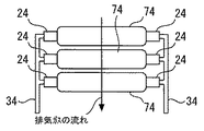
次に、この発明の実施の形態6について説明する。図12は、実施の形態6の構成を示す模式図である。上述した実施の形態1〜5では、触媒72を内包するケーシング74の長手方向に排気ガスを流すようにしたが、図12に示すように、実施の形態6ではケーシング74の長手方向に対して直交する方向に排気ガスを流すようにしている。
Embodiment 6 FIG.
Next, a sixth embodiment of the present invention will be described. FIG. 12 is a schematic diagram showing the configuration of the sixth embodiment. In the first to fifth embodiments described above, the exhaust gas is caused to flow in the longitudinal direction of the
このように、ケーシング74の長手方向に対して直交する方向に排気ガスを流すことで、排気ガスから触媒72への熱交換率を高めることができる。従って、脱水素反応による触媒72の温度低下を最小限に抑えることができ、脱水素反応の効率を最大限に高めることが可能となる。
Thus, by flowing the exhaust gas in a direction orthogonal to the longitudinal direction of the
また、排気ガスの触媒72の全域に直接当てることで、触媒72に温度勾配が生じることを抑えることができる。従って、触媒72の内部で均一に脱水素反応を生じさせることができ、反応効率を向上させることができる。
Further, by directly applying the exhaust gas to the entire area of the
図13は、排気ガスの流れ方向に複数のケーシング74を配置した例を示す模式図である。このように、複数のケーシング74を並べて配置することで、触媒72の容積(表面積)を拡大することができ、水素の生成量を増大することができる。
FIG. 13 is a schematic diagram showing an example in which a plurality of
以上説明したように実施の形態6によれば、ケーシング74の長手方向に対して直交方向に排気ガスを流すようにしたため、排気ガスから触媒72への熱交換率を高めることができる。これにより、触媒72の温度低下を最小限に抑えることができ、脱水素反応の効率を最大限に高めることが可能となる。
As described above, according to the sixth embodiment, since the exhaust gas is caused to flow in a direction orthogonal to the longitudinal direction of the
なお、上述した各実施形態では、水素化ガソリンのみを燃料として供給し、水素化ガソリンから脱離した水素と、脱離後の燃料を内燃機関10に供給する一元燃料のシステムに本発明を適用した例を示したが、燃料としてメチルシクロヘキサンと通常のガソリンの2種類を供給し、メチルシクロヘキサンから脱離させた水素と、通常のガソリンを内燃機関10に供給する2元燃料のシステムに適用することも勿論可能である。 In each of the above-described embodiments, the present invention is applied to a system of one-way fuel that supplies only hydrogenated gasoline as fuel, desorbs hydrogen from hydrogenated gasoline, and supplies the desorbed fuel to the internal combustion engine 10. In this example, two types of fuel, methylcyclohexane and normal gasoline, are supplied as fuel, and the hydrogen is desorbed from methylcyclohexane and the normal fuel is supplied to the internal combustion engine 10. Of course it is also possible.
14 排気管
18 水素供給用インジェクタ
24 水素化ガソリンインジェクタ
25 排気温度センサ
30 触媒
74 ケーシング
78 温度センサ
82 触媒温度センサ
DESCRIPTION OF
Claims (11)
前記ケーシングの内部に設けられた触媒と、
前記ケーシングの前記端部に設けられ、前記触媒に向けて有機ハイドライド含有燃料を供給する燃料供給手段と、
前記触媒上での脱水素反応により前記有機ハイドライド含有燃料から取り出された水素を内燃機関に供給する水素供給手段と、
を備えたことを特徴とする水素利用内燃機関。 A casing that is introduced into the exhaust passage of the internal combustion engine and has an end disposed outside the exhaust passage;
A catalyst provided inside the casing;
A fuel supply means provided at the end of the casing and configured to supply an organic hydride-containing fuel toward the catalyst;
Hydrogen supply means for supplying hydrogen extracted from the organic hydride-containing fuel to the internal combustion engine by a dehydrogenation reaction on the catalyst;
An internal combustion engine using hydrogen.
前記燃料供給手段は、前記ケーシングの両側の前記端部に設けられたことを特徴とする請求項1〜3のいずれかに記載の水素利用内燃機関。 The ends on both sides of the casing are disposed outside the exhaust passage;
The hydrogen-utilizing internal combustion engine according to claim 1, wherein the fuel supply means is provided at the end portions on both sides of the casing.
有機ハイドライド含有燃料を供給していない前記燃料供給手段の前記先端温度が所定値以上となった場合に、前記燃料供給手段の切り換えを行うことを特徴とする請求項6記載の水素利用内燃機関。 Means for detecting a tip temperature on the catalyst side of the fuel supply means;
7. The hydrogen-utilizing internal combustion engine according to claim 6, wherein the fuel supply means is switched when the tip temperature of the fuel supply means not supplying the organic hydride-containing fuel exceeds a predetermined value.
有機ハイドライド含有燃料を供給している側の前記触媒の温度が所定値以下となった場合に、前記燃料供給手段の切り換えを行うことを特徴とする請求項6記載の水素利用内燃機関。 Means for detecting the temperature of the catalyst;
7. The hydrogen-using internal combustion engine according to claim 6, wherein the fuel supply means is switched when the temperature of the catalyst on the side supplying the organic hydride-containing fuel falls below a predetermined value.
Priority Applications (1)
| Application Number | Priority Date | Filing Date | Title |
|---|---|---|---|
| JP2004116606A JP2005299499A (en) | 2004-04-12 | 2004-04-12 | Internal combustion engine using hydrogen |
Applications Claiming Priority (1)
| Application Number | Priority Date | Filing Date | Title |
|---|---|---|---|
| JP2004116606A JP2005299499A (en) | 2004-04-12 | 2004-04-12 | Internal combustion engine using hydrogen |
Publications (1)
| Publication Number | Publication Date |
|---|---|
| JP2005299499A true JP2005299499A (en) | 2005-10-27 |
Family
ID=35331354
Family Applications (1)
| Application Number | Title | Priority Date | Filing Date |
|---|---|---|---|
| JP2004116606A Withdrawn JP2005299499A (en) | 2004-04-12 | 2004-04-12 | Internal combustion engine using hydrogen |
Country Status (1)
| Country | Link |
|---|---|
| JP (1) | JP2005299499A (en) |
Cited By (3)
| Publication number | Priority date | Publication date | Assignee | Title |
|---|---|---|---|---|
| EP2065589A2 (en) | 2007-11-30 | 2009-06-03 | Hitachi, Ltd. | Engine system |
| EP2105601A1 (en) | 2008-03-28 | 2009-09-30 | Hitachi Ltd. | Engine system |
| DE102009009651A1 (en) | 2008-04-04 | 2009-12-10 | Hitachi, Ltd. | engine system |
-
2004
- 2004-04-12 JP JP2004116606A patent/JP2005299499A/en not_active Withdrawn
Cited By (8)
| Publication number | Priority date | Publication date | Assignee | Title |
|---|---|---|---|---|
| EP2065589A2 (en) | 2007-11-30 | 2009-06-03 | Hitachi, Ltd. | Engine system |
| JP2009133248A (en) * | 2007-11-30 | 2009-06-18 | Hitachi Ltd | Engine system |
| US8171894B2 (en) | 2007-11-30 | 2012-05-08 | Hitachi, Ltd. | Engine system |
| EP2105601A1 (en) | 2008-03-28 | 2009-09-30 | Hitachi Ltd. | Engine system |
| US8096269B2 (en) | 2008-03-28 | 2012-01-17 | Hitachi, Ltd. | Engine system |
| DE102009009651A1 (en) | 2008-04-04 | 2009-12-10 | Hitachi, Ltd. | engine system |
| US8033255B2 (en) | 2008-04-04 | 2011-10-11 | Hitachi, Ltd. | Engine system |
| DE102009009651B4 (en) * | 2008-04-04 | 2012-06-06 | Hitachi, Ltd. | engine system |
Similar Documents
| Publication | Publication Date | Title |
|---|---|---|
| JP4033163B2 (en) | Internal combustion engine using hydrogen | |
| JP4039383B2 (en) | Internal combustion engine using hydrogen | |
| US7412947B2 (en) | Internal combustion engine system with hydrogen generation capability | |
| AU2019445332B2 (en) | Reforming system and engine system | |
| JP4687666B2 (en) | Engine system | |
| US6908700B2 (en) | Fuel cell system for vehicle | |
| US20170333843A1 (en) | Fuel reformer | |
| JP2021173182A (en) | Control device | |
| JP2005299499A (en) | Internal combustion engine using hydrogen | |
| JP2006257906A (en) | Internal combustion engine using hydrogen | |
| JP2005299500A (en) | Internal combustion engine using hydrogen | |
| JP2001248506A (en) | Fuel reformer for internal combustion engine and internal combustion engine with fuel reformer | |
| JP2009097425A (en) | Fuel reformer | |
| JP4798014B2 (en) | Internal combustion engine using hydrogen | |
| JP2006022731A (en) | Internal combustion engine using hydrogen | |
| JP2009108755A (en) | Exhaust emission control device of internal combustion engine | |
| JP4835574B2 (en) | VEHICLE CONTROL DEVICE HAVING HYDROGEN GENERATION SYSTEM | |
| JP2009228444A (en) | Gaseous fuel supplying device | |
| JP6344295B2 (en) | Hybrid vehicle | |
| JP4461993B2 (en) | Internal combustion engine system using hydrogen | |
| JP4569373B2 (en) | Internal combustion engine using hydrogen | |
| JP2014185548A (en) | Exhaust purification device of internal combustion engine | |
| JP2006170182A (en) | Internal combustion engine with fuel reformer | |
| JP4924328B2 (en) | Vehicle with hydrogen generation system | |
| JP2007231900A (en) | Fuel reformer for internal combustion engine |
Legal Events
| Date | Code | Title | Description |
|---|---|---|---|
| A300 | Application deemed to be withdrawn because no request for examination was validly filed |
Free format text: JAPANESE INTERMEDIATE CODE: A300 Effective date: 20070703 |