JP2006022731A - Internal combustion engine using hydrogen - Google Patents
Internal combustion engine using hydrogen Download PDFInfo
- Publication number
- JP2006022731A JP2006022731A JP2004202033A JP2004202033A JP2006022731A JP 2006022731 A JP2006022731 A JP 2006022731A JP 2004202033 A JP2004202033 A JP 2004202033A JP 2004202033 A JP2004202033 A JP 2004202033A JP 2006022731 A JP2006022731 A JP 2006022731A
- Authority
- JP
- Japan
- Prior art keywords
- hydrogen
- catalyst
- casing
- exhaust
- combustion engine
- Prior art date
- Legal status (The legal status is an assumption and is not a legal conclusion. Google has not performed a legal analysis and makes no representation as to the accuracy of the status listed.)
- Withdrawn
Links
Images


Classifications
-
- Y—GENERAL TAGGING OF NEW TECHNOLOGICAL DEVELOPMENTS; GENERAL TAGGING OF CROSS-SECTIONAL TECHNOLOGIES SPANNING OVER SEVERAL SECTIONS OF THE IPC; TECHNICAL SUBJECTS COVERED BY FORMER USPC CROSS-REFERENCE ART COLLECTIONS [XRACs] AND DIGESTS
- Y02—TECHNOLOGIES OR APPLICATIONS FOR MITIGATION OR ADAPTATION AGAINST CLIMATE CHANGE
- Y02T—CLIMATE CHANGE MITIGATION TECHNOLOGIES RELATED TO TRANSPORTATION
- Y02T10/00—Road transport of goods or passengers
- Y02T10/10—Internal combustion engine [ICE] based vehicles
- Y02T10/12—Improving ICE efficiencies
-
- Y—GENERAL TAGGING OF NEW TECHNOLOGICAL DEVELOPMENTS; GENERAL TAGGING OF CROSS-SECTIONAL TECHNOLOGIES SPANNING OVER SEVERAL SECTIONS OF THE IPC; TECHNICAL SUBJECTS COVERED BY FORMER USPC CROSS-REFERENCE ART COLLECTIONS [XRACs] AND DIGESTS
- Y02—TECHNOLOGIES OR APPLICATIONS FOR MITIGATION OR ADAPTATION AGAINST CLIMATE CHANGE
- Y02T—CLIMATE CHANGE MITIGATION TECHNOLOGIES RELATED TO TRANSPORTATION
- Y02T10/00—Road transport of goods or passengers
- Y02T10/10—Internal combustion engine [ICE] based vehicles
- Y02T10/30—Use of alternative fuels, e.g. biofuels
Landscapes
- Output Control And Ontrol Of Special Type Engine (AREA)
- Exhaust Gas After Treatment (AREA)
Abstract
Description
この発明は、水素利用内燃機関に関する。 The present invention relates to a hydrogen-utilizing internal combustion engine.
従来、例えば特開2003−343360号公報に開示されるように、水素生成機能を有する内燃機関のシステムが知られている。このシステムは、具体的には、デカリン等の有機ハイドライドを含む水素化燃料を原料として、水素リッチガスと、ナフタレン等の脱水素生成物とを生成する機構、並びに、生成された水素リッチガスを燃料として作動する水素エンジンを備えている。 Conventionally, as disclosed in, for example, Japanese Patent Application Laid-Open No. 2003-343360, an internal combustion engine system having a hydrogen generation function is known. Specifically, this system uses a hydrogenated fuel containing an organic hydride such as decalin as a raw material to generate a hydrogen rich gas and a dehydrogenated product such as naphthalene, and the generated hydrogen rich gas as a fuel. It has a working hydrogen engine.
上記公報に開示されるシステムは、水素エンジンの作動中に、その作動に伴って発生する熱を利用して、水素化燃料を水素リッチガスと脱水素生成物に分離する。より具体的には、水素化燃料を触媒上に噴射し、触媒上で脱水素化反応を起こさせて水素を取り出している。この際、水素を効率良く取り出すために、触媒をエンジンの廃熱を用いて加熱している。 The system disclosed in the above publication separates hydrogenated fuel into a hydrogen-rich gas and a dehydrogenated product using heat generated during the operation of the hydrogen engine. More specifically, hydrogenated fuel is injected onto the catalyst, and a dehydrogenation reaction is caused on the catalyst to take out hydrogen. At this time, in order to efficiently extract hydrogen, the catalyst is heated using the waste heat of the engine.
エンジンの廃熱を用いて触媒を加熱する方法として、エンジンの排気ガスのエネルギーを用いて触媒を加熱することが考えられる。しかしながら、排気ガスのエネルギーを用いて触媒を加熱して水素を取り出す場合に、排気熱を有効に利用できないとエンジンが要求する水素量に対して取り出した水素量が不足してしまう場合がある。 As a method of heating the catalyst using the waste heat of the engine, it is conceivable to heat the catalyst using the energy of the exhaust gas of the engine. However, when hydrogen is extracted by heating the catalyst using the energy of the exhaust gas, if the exhaust heat cannot be used effectively, the amount of hydrogen extracted with respect to the amount of hydrogen required by the engine may be insufficient.
また、内燃機関から排出された排気ガスを浄化する必要があるが、脱水素反応のために排気ガスのエネルギーを用いると、排気を浄化するための触媒に供給される熱量が減少して排気浄化性能が低下するという問題が生じる。従って、脱水素化反応の性能と排気浄化性能を共に向上させる必要がある。 In addition, it is necessary to purify the exhaust gas discharged from the internal combustion engine. However, if the energy of the exhaust gas is used for the dehydrogenation reaction, the amount of heat supplied to the catalyst for purifying the exhaust gas is reduced, thereby purifying the exhaust gas. The problem is that the performance is degraded. Therefore, it is necessary to improve both the performance of the dehydrogenation reaction and the exhaust purification performance.
この発明は、上述のような課題を解決するためになされたもので、排気ガスのエネルギーを用いて脱水素化反応を起こす水素利用機関において、反応効率を向上させて水素の生成量を増大させるとともに、脱水素化反応性能と排気浄化性能を共に向上させることを目的とする。 The present invention has been made to solve the above-described problems. In a hydrogen-using engine that causes a dehydrogenation reaction using the energy of exhaust gas, the reaction efficiency is improved and the amount of hydrogen generated is increased. At the same time, it aims at improving both dehydrogenation reaction performance and exhaust gas purification performance.
第1の発明は、上記の目的を達成するため、内燃機関の排気通路の内部に導入されたケーシングと、前記排気通路内において、前記ケーシングの周辺を囲むように配置された排気浄化触媒と、前記ケーシングの内部に設けられた脱水素反応触媒と、前記脱水素反応触媒に向けて有機ハイドライド含有燃料を供給する燃料供給手段と、前記脱水素反応触媒上での脱水素反応により前記有機ハイドライド含有燃料から取り出された水素を内燃機関に供給する水素供給手段と、を備えたことを特徴とする。 In order to achieve the above object, a first invention provides a casing introduced into an exhaust passage of an internal combustion engine, an exhaust purification catalyst disposed in the exhaust passage so as to surround the periphery of the casing, A dehydrogenation reaction catalyst provided in the casing; a fuel supply means for supplying an organic hydride-containing fuel toward the dehydrogenation reaction catalyst; and the organic hydride-containing material by a dehydrogenation reaction on the dehydrogenation reaction catalyst. And hydrogen supply means for supplying hydrogen taken out of the fuel to the internal combustion engine.
第2の発明は、第1の発明において、前記ケーシングが前記排気通路の長手方向に延在するように設けられたことを特徴とする。 According to a second invention, in the first invention, the casing is provided so as to extend in a longitudinal direction of the exhaust passage.
第3の発明は、第1又は第2の発明において、前記ケーシングの端部が前記排気通路の外に配置され、前記燃料供給手段が前記ケーシングの前記端部に設けられたことを特徴とする。 A third invention is characterized in that, in the first or second invention, an end of the casing is disposed outside the exhaust passage, and the fuel supply means is provided at the end of the casing. .
第1の発明によれば、脱水素反応触媒が内部に設けられたケーシングを排気通路の内部に導入したため、脱水素反応触媒の周囲を排気ガスで囲むことができ、排気ガスの熱を脱水素反応触媒に十分に与えることが可能となる。また、排気通路内において、ケーシングの周辺を囲むように排気浄化触媒を設けたため、排気浄化触媒内で排気ガス中の未燃成分を燃焼させた際に発生する燃焼熱をケーシング内の脱水素反応触媒へ与えることができる。従って、排気ガスの排気熱と排気浄化触媒における燃焼熱を脱水素反応触媒へ与えることができ、脱水素反応触媒への熱供給を確実に行うことができる。更に、ケーシングが設けられた領域の近傍で脱水素反応と排気浄化の双方を行うことができるため、システムの小型化を達成することができる。 According to the first invention, since the casing provided with the dehydrogenation reaction catalyst is introduced into the exhaust passage, the periphery of the dehydrogenation reaction catalyst can be surrounded by the exhaust gas, and the heat of the exhaust gas is dehydrogenated. It is possible to sufficiently supply the reaction catalyst. In addition, since the exhaust purification catalyst is provided in the exhaust passage so as to surround the periphery of the casing, the combustion heat generated when the unburned components in the exhaust gas are burned in the exhaust purification catalyst is used for the dehydrogenation reaction in the casing. Can be applied to the catalyst. Therefore, exhaust heat of the exhaust gas and combustion heat in the exhaust purification catalyst can be given to the dehydrogenation reaction catalyst, and heat supply to the dehydrogenation reaction catalyst can be performed reliably. Furthermore, since both the dehydrogenation reaction and the exhaust purification can be performed in the vicinity of the region where the casing is provided, the system can be reduced in size.
第2の発明によれば、ケーシングを排気通路の長手方向に延在するように設けたため、排気ガスの流れ方向とケーシングの長手方向を一致させることができ、脱水素反応触媒の表面積を最大限に拡大することができる。従って、脱水素反応触媒の利用効率を高めることができ、脱水素反応の反応量を増大させることができる。 According to the second invention, since the casing is provided so as to extend in the longitudinal direction of the exhaust passage, the flow direction of the exhaust gas and the longitudinal direction of the casing can be matched, and the surface area of the dehydrogenation reaction catalyst is maximized. Can be expanded. Therefore, the utilization efficiency of the dehydrogenation reaction catalyst can be increased, and the reaction amount of the dehydrogenation reaction can be increased.
第3の発明によれば、ケーシングの端部を排気通路の外に配置し、燃料供給手段をケーシングの端部に設けたため、排気通路に燃料供給手段を貫通させる必要がなくなり、排気通路の内部の脱水素反応触媒に向けて有機ハイドライド含有燃料を供給する構造を容易に製造することができる。 According to the third invention, since the end of the casing is disposed outside the exhaust passage and the fuel supply means is provided at the end of the casing, there is no need to penetrate the fuel supply means through the exhaust passage. A structure for supplying an organic hydride-containing fuel toward the dehydrogenation reaction catalyst can be easily manufactured.
以下、図面に基づいてこの発明の一実施形態について説明する。尚、各図において共通する要素には、同一の符号を付して重複する説明を省略する。なお、以下の実施の形態によりこの発明が限定されるものではない。 An embodiment of the present invention will be described below with reference to the drawings. In addition, the same code | symbol is attached | subjected to the element which is common in each figure, and the overlapping description is abbreviate | omitted. The present invention is not limited to the following embodiments.
図1は、本発明の各実施形態に係る内燃機関システムの構成を説明するための図である。このシステムは、内燃機関10を備えている。内燃機関10には、吸気管12および排気管14が連通している。
FIG. 1 is a diagram for explaining a configuration of an internal combustion engine system according to each embodiment of the present invention. This system includes an internal combustion engine 10. An intake pipe 12 and an
吸気管12には、吸入空気量を制御するためのスロットルバルブ16が組み込まれている。スロットルバルブ16の下流には、水素供給用インジェクタ18が配置されている。また、内燃機関10の吸気ポートには、ガソリン供給用インジェクタ20が配置されている。
A throttle valve 16 for controlling the intake air amount is incorporated in the intake pipe 12. A
水素供給用インジェクタ18には、後述するように、所定の圧力で水素リッチガスが供給されている。水素供給用インジェクタ18は、外部から供給される駆動信号を受けて開弁することにより、その開弁の時間に応じた量の水素リッチガスを吸気管12の内部に噴射することができる。図1に示すシステムでは、水素供給用インジェクタ18を吸気管12に配置することとしているが、その配置はこれに限定されるものではない。すなわち、水素供給用インジェクタ18は、筒内に水素が噴射できるように内燃機関10の本体に組み込んでも良い。
A hydrogen rich gas is supplied to the
ガソリン供給用インジェクタ20には、後述するように、所定の圧力でガソリンが供給されている。ガソリン供給用インジェクタ20は、外部から供給される駆動信号を受けて開弁することにより、その開弁の時間に応じた量のガソリンを吸気ポート内に噴射することができる。 As will be described later, gasoline is supplied to the gasoline supply injector 20 at a predetermined pressure. The gasoline supply injector 20 opens a valve in response to a drive signal supplied from the outside, so that an amount of gasoline corresponding to the valve opening time can be injected into the intake port.
排気管14には、脱水素反応器22が装着されている。また、脱水素反応器22の上部には、水素化ガソリンインジェクタ24が組み付けられている。
A
水素化ガソリンインジェクタ24は、後述するように、所定の圧力で水素化ガソリンの供給を受けており、外部から供給される駆動信号を受けて開弁することにより、その開弁の時間に応じた量の水素化ガソリンを脱水素反応器22の内部に供給することができる。ここで、内燃機関10が必要とする水素量は、内燃機関10の運転状態に応じて変動する。ECU80は、内燃機関10が必要とする水素量と、運転状態(機関回転数、負荷(スロットル開度))との関係を定めたマップを記憶しており、このマップから必要水素量を求め、水素化ガソリンインジェクタ24の開弁・閉弁状態を制御する。また、脱水素反応器22は、排気管14から放射される排気熱を利用して、上記の如く供給される水素化ガソリンを水素リッチガスと脱水素化ガソリンとに分離し、それらを流出させる機能を有している。
As will be described later, the hydrogenated
排気管14には、脱水素反応器22の上流において、排気温度センサ25が組み込まれている。また、排気管14には、脱水素反応器22の下流において、O2センサ26およびNOxセンサ28が組み込まれている。O2センサ26は、排気ガス中の酸素の有無を基礎として、排気空燃比に応じた出力を発するセンサである。また、NOxセンサ28は、排気ガス中のNOx濃度に応じた出力を発するセンサである。これらのセンサ26,28の下流には、排気ガスを浄化するための触媒30が配置されている。
An exhaust temperature sensor 25 is incorporated in the
本実施形態のシステムは、水素化ガソリンタンク32を備えている。水素化ガソリンタンク32の中には、一般的なガソリンに比して有機ハイドライドを多量に含む水素化ガソリンが貯留される。ここで、「有機ハイドライド」とは、300℃程度の温度で脱水素反応を起こす炭化水素(HC)成分であり、具体的には、デカリンやシクロヘキサンがこれに該当する。
The system of this embodiment includes a hydrogenated
通常のガソリン(LFT−1C)には、トルエンが40%程度含まれている。トルエンを水素化すると、有機ハイドライドであるメチルシクロヘキサン(C7H14)を生成することができる。つまり、通常のガソリンを原料として、その中に含まれるトルエンを水素化すると、メチルシクロヘキサンを40%程度含有する水素化ガソリンを生成することができる。本実施形態では、便宜上、水素化ガソリンタンク32には、このような組成を有する水素化ガソリンが給油されるものとする。
Ordinary gasoline (LFT-1C) contains about 40% of toluene. When toluene is hydrogenated, methylcyclohexane (C 7 H 14 ), which is an organic hydride, can be produced. That is, hydrogenation gasoline containing about 40% of methylcyclohexane can be generated by hydrogenating toluene contained in ordinary gasoline as a raw material. In the present embodiment, for the sake of convenience, the
水素化ガソリンタンク32には、水素化ガソリン供給管34が連通している。水素化ガソリン供給管34は、その途中にポンプ36を備え、その端部において水素化ガソリンインジェクタ24に連通している。水素化ガソリンタンク32内の水素化ガソリンは、内燃機関の運転中に、ポンプ36により汲み上げられて、所定の圧力で水素化ガソリンインジェクタ24に供給される。
A hydrogenated
水素化ガソリンインジェクタ24は、上述した通り、脱水素反応器22の上部に組み付けられている。脱水素反応器22は、排気熱を利用して水素化ガソリンを処理するための装置である。このため、内燃機関の運転中は、脱水素反応器22の内部は、300℃を超える温度に上昇する。
The
水素化ガソリンインジェクタ24は、その内部温度に直接晒されるのを避けるべく、脱水素反応器22の上方空間に主要部分が突出するように組み付けられている。このため、本実施形態のシステムによれば、水素化ガソリンインジェクタ24の温度が、不当に高温となることはない。
The
尚、図1に示すシステムでは、水素化ガソリンインジェクタ24を空冷することとしているが、その冷却の手法はこれに限定されるものではない。例えば、内燃機関10の冷却水を水素化ガソリンインジェクタ24の周囲に導くための冷却水通路を設けて、水素化ガソリンインジェクタ24を水冷することとしても良い。
In the system shown in FIG. 1, the
脱水素反応器22の内部には、反応室が形成されている。水素化ガソリンインジェクタ24から噴射された燃料は、その反応室の内部で水素リッチガスと脱水素化ガソリンとに分離され、脱水素反応器22に接続された管路38に導かれる。脱水素反応器22には管路38を介して分離装置40が連通している。
A reaction chamber is formed inside the
既述した通り、本実施形態において用いられる水素化ガソリンは、通常のガソリンに含まれているトルエンを、有機ハイドライド化したものである。従って、その水素化ガソリンに脱水素処理を施せば、その結果生成されるのは、水素リッチガスと通常のガソリンである。具体的には、有機ハイドライドであるメチルシクロヘキサンC7H14は、脱水素反応により、下記の通り水素H2とトルエンC7H8に分離される。
C7H14→C7H8+3H2 ・・・(1)
(1)式で示される脱水素反応は吸熱反応である。
As described above, the hydrogenated gasoline used in the present embodiment is obtained by organically hydrating toluene contained in normal gasoline. Therefore, if the hydrogenated gasoline is subjected to a dehydrogenation treatment, hydrogen-rich gas and ordinary gasoline are generated as a result. Specifically, methylcyclohexane C 7 H 14 which is an organic hydride is separated into hydrogen H 2 and toluene C 7 H 8 as follows by a dehydrogenation reaction.
C 7 H 14 → C 7 H 8 + 3H 2 (1)
The dehydrogenation reaction represented by the formula (1) is an endothermic reaction.
このため、脱水素反応器22から分離装置40へは、具体的には、水素リッチガスと、通常のガソリンとの混合物が供給されることになる。
For this reason, specifically, a mixture of hydrogen-rich gas and ordinary gasoline is supplied from the
分離装置40は、脱水素反応器22から供給される高温の水素リッチガスおよび脱水素化ガソリン(通常のガソリン)を冷却して、それらを分離する機能を有している。分離装置40は、内燃機関10と同様に冷却水の循環により水冷されている。このため、分離装置40は、効率良く水素リッチガス及び脱水素化ガソリンを冷却することができる。
The
分離装置40の底部には、冷却されることにより液化した脱水素化ガソリンを貯留しておくための液体貯留スペースが設けられている。また、その貯留スペースの上方には、気体のまま残存する水素リッチガスを貯留するための気体貯留スペースが確保されている。分離装置40には、液体貯留スペースに連通するようにガソリン管路42が連通していると共に、気体貯留スペースに連通するように水素管路44が連通している。
A liquid storage space for storing dehydrogenated gasoline liquefied by being cooled is provided at the bottom of the
ガソリン管路42は、ガソリンバッファタンク48に連通している。図1には、水素化ガソリンタンク32とガソリンバッファタンク48とが離れた位置に配置された構成が示されているが、その構成はこれに限定されるものではない。すなわち、それらは、単一の筐体に収めることとしてもよい。
The
ガソリンバッファタンク48には、液量センサ58が組み付けられている。液量センサ58は、その内部に貯留されている脱水素化ガソリンの液量に応じた出力を発するセンサである。また、ガソリンバッファタンク48には、ガソリン供給管60が連通している。ガソリン供給管60は、その途中にポンプ62を備え、その端部においてガソリン供給用インジェクタ20に連通している。ガソリンバッファタンク48内の脱水素化ガソリンは、内燃機関の運転中に、ポンプ62により汲み上げられて、所定の圧力でガソリン供給用インジェクタ20に供給される。
A
水素管路44は、水素バッファタンク64に連通している。また、水素管路44には、分離装置40内の水素リッチガスを水素バッファタンク64に圧送するためのポンプ66と、ポンプ66の吐出側圧力が過大となるのを防ぐためのリリーフ弁68が組み込まれている。ポンプ66およびリリーフ弁68によれば、水素バッファタンク64内に、その内圧が過剰とならない範囲で水素リッチガスを送り込むことができる。
The
水素バッファタンク64には、圧力センサ70が組み付けられている。圧力センサ70は、水素バッファタンク64の内圧に応じた出力を発するセンサである。圧力センサ70の出力によれば、水素バッファタンク64内に貯留されている水素リッチガスの量を推定することができる。
A
水素バッファタンク64には、水素供給管71が連通している。水素供給管71は、その途中にレギュレータ73を備え、その端部において水素供給用インジェクタ18に連通している。このような構成によれば、水素供給用インジェクタ18には、水素バッファタンク64に水素リッチガスが貯留されていることを条件に、レギュレータ73により調整される圧力により水素リッチガスが供給される。
A
本実施形態のシステムは、ECU80を備えている。ECU80は、本実施形態のシステムを制御する機能を有している。すなわち、ECU80には、上述したO2センサ26、NOxセンサ28、液量センサ58および圧力センサ70などの各種センサの出力が供給されている。また、ECU80には、上述したポンプ36,62,66、並びにインジェクタ18,20,24などのアクチュエータが接続されている。ECU80は、それらのセンサ出力を基礎として所定の処理を行うことにより、上述した各種のアクチュエータを適当に駆動することができる。
The system of this embodiment includes an ECU 80. The ECU 80 has a function of controlling the system of this embodiment. That is, the ECU 80 is supplied with outputs from various sensors such as the O 2 sensor 26, the
このように構成された本実施形態のシステムでは、水素化ガソリンを脱水素化処理して得られたガソリン(脱水素燃料)と水素の両方を使用してリーンバーン燃焼により内燃機関10を運転することができる。リーンバーン燃焼による運転によれば、燃費、効率を向上させることができる。また、NOXの排出を抑えることができるため、エミッションを向上させることができる。 In the system of the present embodiment configured as described above, the internal combustion engine 10 is operated by lean burn combustion using both gasoline (dehydrogenated fuel) obtained by dehydrogenating hydrogenated gasoline and hydrogen. be able to. According to the operation by lean burn combustion, fuel efficiency and efficiency can be improved. Further, it is possible to suppress the emission of NO X, it is possible to improve the emission.
また、本実施形態のシステムによれば、高負荷、高回転域等において出力が要求される場合は、ガソリン(脱水素燃料)のみを使用したストイキ燃焼により内燃機関10を運転することができる。 Further, according to the system of the present embodiment, when output is required in a high load, high rotation range, etc., the internal combustion engine 10 can be operated by stoichiometric combustion using only gasoline (dehydrogenated fuel).
次に、図2及び図3に基づいて、脱水素反応器22の構成を詳細に説明する。図2は、脱水素反応器22の構成を示す断面図である。図2に示すように、脱水素反応を生じさせるための触媒72はケーシング74内に設けられ、ケーシング74は排気ガスの流れ方向にその長手方向を向けた状態で排気管14内に挿入されている。ケーシング74の両端部は排気管14の外に突出しており、上端には水素化ガソリンインジェクタ24が設けられている。また、ケーシング74が挿入された領域の排気管14の外周には、断熱材76が巻き付けられている。
Next, based on FIG.2 and FIG.3, the structure of the
ケーシング74と排気管14の内壁との間には、リング状に排気浄化触媒78が挿入されている。そして、排気管14内を流れる排気ガスが排気浄化触媒78が設けられた領域を通過するように構成されている。排気浄化触媒78は、通常の三元触媒と同様の機能を有しており、排気ガス中に含まれる未燃成分(HC,CO)を酸化し、排気ガス中の窒素酸化物(NOX)を還元する機能を有している。本実施形態の内燃機関システムでは、主としてリーンバーン燃焼を行うため、排気ガス中における窒素酸化物の含有量は比較的少ない。従って、排気浄化触媒78では、主として排気ガス中の未燃成分を燃焼して酸化する反応が行われる。
An
図2に示すように、排気ガスの流れ方向とケーシング74の長手方向を一致させることで、排気管14の径の拡大を最小限に抑えた状態で、触媒72の容積(表面積)を最大限に拡大することができる。従って、触媒72の利用効率を高めることができる。
As shown in FIG. 2, the volume (surface area) of the
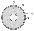
図3は、図2の一点鎖線I−I’に沿った断面を示す断面図である。図3に示すように、ケーシング74は排気管14内の中心に配置されており、水素化ガソリンが供給される領域の外側に排気ガスが流れる領域が配置された2層構造が構成されている。そして、排気ガスが流れる領域に排気浄化触媒78が挿入されている。これにより、排気管14内において、ケーシング74は外側を流れる排気ガスによって囲まれることになり、触媒72への熱供給を効率良く行うことが可能となる。
FIG. 3 is a cross-sectional view showing a cross section taken along the alternate long and short dash line I-I ′ of FIG. 2. As shown in FIG. 3, the
また、排気浄化触媒78では、主として排気ガス中の未燃成分の燃焼が行われるため、排気浄化触媒78において燃焼熱が発生する。従って、排気ガスの排気熱と燃焼による反応熱をケーシング74内の触媒72へ与えることができる。
Further, in the
特に、リーンバーン燃焼の場合、ストイキ燃焼よりも排気温度が低下するため、排気熱のみでは触媒72への熱供給が不足する場合がある。従って、排気浄化触媒78による燃焼熱をケーシング74内に供給することで、触媒72を確実に昇温させることができ、反応効率を高めることが可能となる。
In particular, in the case of lean burn combustion, the exhaust gas temperature is lower than that in stoichiometric combustion, so that heat supply to the
これにより、排気ガスの排気熱、および排気浄化触媒78における燃焼熱を利用して、触媒72における脱水素反応を促進することができる。上述したように脱水素反応は吸熱反応であるため、反応量が増えるに従って触媒72の温度が低下して反応効率が低下する場合があるが、本実施形態の構成によれば、反応量が多い場合であっても触媒72の内部温度の低下を最小限に抑えることが可能となる。これにより、大量の水素を常に安定して生成することができる。また、ケーシング74が挿入された領域において排気管14に断熱材76を巻いているため、排気熱が外部に漏れることを最小限に抑えることができ、排気熱の利用効率をより高めることができる。
Thereby, the dehydrogenation reaction in the
また、排気浄化触媒78を脱水素反応器22に設けることができるため、排気管14のより上流側へ排気を浄化するための触媒を配置することができる。従って、排気浄化触媒78に対してより高温の排気ガスを送ることが可能となり、排気浄化触媒78をより短時間で暖機することが可能となる。これにより、機関始動後の早期に排気浄化触媒78を活性状態にすることができ、排気浄化性能を発揮させることができる。
Further, since the
更に、本実施形態の構成によれば、ケーシング74の端部を排気管14の外側に突出させているため、端部に水素化ガソリンインジェクタ24を装着するだけで触媒72に燃料を供給することが可能となる。これにより、触媒72に燃料を供給するための開口を排気管14自体に設ける必要がなくなり、簡素な構成で触媒72に燃料を供給することが可能となる。従って、脱水素反応器22の生産性を高めることが可能となる。また、脱水素反応器22を2層構造にしたため、3層以上の構造と比較すると径を縮小することができ、システムへの搭載性を高めることが可能となる。また、脱水素反応器22を2層構造にしたため、製造を容易に行うことが可能となる。
Furthermore, according to the configuration of the present embodiment, since the end portion of the
また、脱水素反応器22内に排気浄化触媒78を設けているため、脱水素反応器22において水素生成と排気浄化の双方を行うことができる。従って、脱水素反応器22の下流の触媒30を小型化することができ、排気浄化触媒78の浄化機能によっては触媒30を設ける必要がなくなる。これにより、システムを簡素に構成することが可能となり、システムの小型化を達成することができる。
Further, since the
なお、図2及び図3では、脱水素反応が行われる領域の外側に排気ガスの流路を設けた2層構造の例を示したが、本発明はこの構造に限定されるものではない。図4は、脱水素反応器22の他の構成を示す模式図であって、図3と同様に排気ガスの流れ方向と直交する方向に沿った断面を示している。図4に示すように、排気管14内にリング状のケーシング74を導入し、リング状のケーシング74の中心部と周囲に排気浄化触媒78を配置しても良い。この構成によっても、排気熱と燃焼熱の双方をケーシング74内の触媒72に与えることができる。
2 and 3, an example of a two-layer structure in which an exhaust gas flow path is provided outside the region where the dehydrogenation reaction is performed is shown, but the present invention is not limited to this structure. FIG. 4 is a schematic view showing another configuration of the
また、図2ではケーシング74の上端部のみに水素化ガソリンインジェクタ24を設けているが、ケーシング74の両端部に水素化ガソリンインジェクタ24をそれぞれ設けて、双方の水素化ガソリンインジェクタ24から触媒72に向けて水素化ガソリンを噴射するようにしても良い。これにより、触媒72における反応効率を高めることができ、水素の生成量を増加させることができる。
Further, in FIG. 2, the
以上説明したように本実施形態によれば、触媒72を内包したケーシング74を排気管14内に挿入し、ケーシング74を高温の排気ガスで囲むようにしたため、排気熱の利用効率を高めることが可能となる。また、排気管14内において、ケーシング74の外側に排気浄化触媒78を設けたため、排気浄化触媒78で未燃成分を燃焼した際の燃焼熱をケーシング74内の触媒72へ与えることができる。従って、排気ガスの排気熱と燃焼による反応熱をケーシング74内の触媒72へ与えることができ、触媒72への熱供給を確実に行うことができる。
As described above, according to the present embodiment, the
これにより、触媒72への熱供給の効率を高めることができ、触媒72の温度の低下を抑制することができるため、触媒72における脱水素反応の効率を高めることが可能となる。従って、大量の水素を常に安定して生成することができる。また、脱水素反応器22において水素生成と排気浄化の双方を行うことができるため、システムを簡素に構成することが可能となり、システムの小型化を達成することができる。
As a result, the efficiency of heat supply to the
14 排気管
18 水素供給用インジェクタ
24 水素化ガソリンインジェクタ
25 排気温度センサ
72 触媒
74 ケーシング
78 排気浄化触媒
14
Claims (3)
前記排気通路内において、前記ケーシングの周辺を囲むように配置された排気浄化触媒と、
前記ケーシングの内部に設けられた脱水素反応触媒と、
前記脱水素反応触媒に向けて有機ハイドライド含有燃料を供給する燃料供給手段と、
前記脱水素反応触媒上での脱水素反応により前記有機ハイドライド含有燃料から取り出された水素を内燃機関に供給する水素供給手段と、
を備えたことを特徴とする水素利用内燃機関。 A casing introduced into the exhaust passage of the internal combustion engine;
In the exhaust passage, an exhaust purification catalyst arranged so as to surround the periphery of the casing;
A dehydrogenation reaction catalyst provided inside the casing;
Fuel supply means for supplying an organic hydride-containing fuel toward the dehydrogenation reaction catalyst;
Hydrogen supply means for supplying hydrogen extracted from the organic hydride-containing fuel to the internal combustion engine by a dehydrogenation reaction on the dehydrogenation reaction catalyst;
An internal combustion engine using hydrogen.
Priority Applications (1)
| Application Number | Priority Date | Filing Date | Title |
|---|---|---|---|
| JP2004202033A JP2006022731A (en) | 2004-07-08 | 2004-07-08 | Internal combustion engine using hydrogen |
Applications Claiming Priority (1)
| Application Number | Priority Date | Filing Date | Title |
|---|---|---|---|
| JP2004202033A JP2006022731A (en) | 2004-07-08 | 2004-07-08 | Internal combustion engine using hydrogen |
Publications (1)
| Publication Number | Publication Date |
|---|---|
| JP2006022731A true JP2006022731A (en) | 2006-01-26 |
Family
ID=35796186
Family Applications (1)
| Application Number | Title | Priority Date | Filing Date |
|---|---|---|---|
| JP2004202033A Withdrawn JP2006022731A (en) | 2004-07-08 | 2004-07-08 | Internal combustion engine using hydrogen |
Country Status (1)
| Country | Link |
|---|---|
| JP (1) | JP2006022731A (en) |
Cited By (1)
| Publication number | Priority date | Publication date | Assignee | Title |
|---|---|---|---|---|
| JP2007239671A (en) * | 2006-03-10 | 2007-09-20 | Hitachi Ltd | Engine system |
-
2004
- 2004-07-08 JP JP2004202033A patent/JP2006022731A/en not_active Withdrawn
Cited By (1)
| Publication number | Priority date | Publication date | Assignee | Title |
|---|---|---|---|---|
| JP2007239671A (en) * | 2006-03-10 | 2007-09-20 | Hitachi Ltd | Engine system |
Similar Documents
| Publication | Publication Date | Title |
|---|---|---|
| JP4033163B2 (en) | Internal combustion engine using hydrogen | |
| JP4039383B2 (en) | Internal combustion engine using hydrogen | |
| JP6233035B2 (en) | Internal combustion engine | |
| JP2006257906A (en) | Hydrogen using internal combustion engine | |
| JP2008215092A (en) | Engine system | |
| US6253545B1 (en) | Internal combustion engine having lean NOx catalyst | |
| JP4178517B2 (en) | Internal combustion engine | |
| JP5567850B2 (en) | Hydrogen production system | |
| JP2008063996A (en) | Internal combustion engine | |
| JP2018009493A (en) | Warming-up method of exhaust emission control catalyst for internal combustion engine | |
| JP2007187111A (en) | Internal combustion engine by use of hydrogen | |
| JP2006220038A (en) | Intake control device for internal combustion engine | |
| JP2006022731A (en) | Internal combustion engine using hydrogen | |
| JP2007138799A (en) | Internal combustion engine using hydrogen | |
| JP2005299500A (en) | Internal combustion engine using hydrogen | |
| JP2008542606A (en) | Device and method for exhaust gas regulation of internal combustion engines | |
| JP2007198274A (en) | Internal combustion engine utilizing hydrogen | |
| JP2005299499A (en) | Internal combustion engine using hydrogen | |
| JP2005105909A (en) | Engine system | |
| PH12017000168A1 (en) | Heat and hydrogen generation device | |
| JP2006125267A (en) | Hydrogen-added internal combustion engine | |
| JP2006249981A (en) | Reformed gas-utilizing internal combustion engine | |
| JP6256794B2 (en) | Fuel reforming system | |
| JP4569373B2 (en) | Internal combustion engine using hydrogen | |
| JP2009108755A (en) | Exhaust emission control device of internal combustion engine |
Legal Events
| Date | Code | Title | Description |
|---|---|---|---|
| A300 | Withdrawal of application because of no request for examination |
Free format text: JAPANESE INTERMEDIATE CODE: A300 Effective date: 20071002 |