EP2065094A2 - Electrostatic precipitator - Google Patents
Electrostatic precipitator Download PDFInfo
- Publication number
- EP2065094A2 EP2065094A2 EP08405265A EP08405265A EP2065094A2 EP 2065094 A2 EP2065094 A2 EP 2065094A2 EP 08405265 A EP08405265 A EP 08405265A EP 08405265 A EP08405265 A EP 08405265A EP 2065094 A2 EP2065094 A2 EP 2065094A2
- Authority
- EP
- European Patent Office
- Prior art keywords
- strand
- winding drum
- electrode
- electrostatic precipitator
- cleaning
- Prior art date
- Legal status (The legal status is an assumption and is not a legal conclusion. Google has not performed a legal analysis and makes no representation as to the accuracy of the status listed.)
- Granted
Links
- 239000012717 electrostatic precipitator Substances 0.000 title claims description 14
- 238000004804 winding Methods 0.000 claims abstract description 33
- 238000004140 cleaning Methods 0.000 claims abstract description 26
- 238000005507 spraying Methods 0.000 claims abstract description 5
- 239000007921 spray Substances 0.000 claims description 13
- 239000000428 dust Substances 0.000 claims description 3
- 239000002245 particle Substances 0.000 claims description 2
- 230000001376 precipitating effect Effects 0.000 claims description 2
- 238000001556 precipitation Methods 0.000 abstract description 7
- 239000012716 precipitator Substances 0.000 abstract 1
- 230000000717 retained effect Effects 0.000 abstract 1
- 238000000034 method Methods 0.000 description 2
- 238000000926 separation method Methods 0.000 description 2
- 229910000831 Steel Inorganic materials 0.000 description 1
- 230000006978 adaptation Effects 0.000 description 1
- 238000002485 combustion reaction Methods 0.000 description 1
- 238000010276 construction Methods 0.000 description 1
- 230000001419 dependent effect Effects 0.000 description 1
- 238000010292 electrical insulation Methods 0.000 description 1
- 230000001747 exhibiting effect Effects 0.000 description 1
- 239000012212 insulator Substances 0.000 description 1
- 238000012423 maintenance Methods 0.000 description 1
- 239000000463 material Substances 0.000 description 1
- 238000005192 partition Methods 0.000 description 1
- 230000000737 periodic effect Effects 0.000 description 1
- 239000010959 steel Substances 0.000 description 1
- 239000002023 wood Substances 0.000 description 1
Images


Classifications
-
- B—PERFORMING OPERATIONS; TRANSPORTING
- B03—SEPARATION OF SOLID MATERIALS USING LIQUIDS OR USING PNEUMATIC TABLES OR JIGS; MAGNETIC OR ELECTROSTATIC SEPARATION OF SOLID MATERIALS FROM SOLID MATERIALS OR FLUIDS; SEPARATION BY HIGH-VOLTAGE ELECTRIC FIELDS
- B03C—MAGNETIC OR ELECTROSTATIC SEPARATION OF SOLID MATERIALS FROM SOLID MATERIALS OR FLUIDS; SEPARATION BY HIGH-VOLTAGE ELECTRIC FIELDS
- B03C3/00—Separating dispersed particles from gases or vapour, e.g. air, by electrostatic effect
- B03C3/34—Constructional details or accessories or operation thereof
- B03C3/40—Electrode constructions
- B03C3/41—Ionising-electrodes
-
- B—PERFORMING OPERATIONS; TRANSPORTING
- B03—SEPARATION OF SOLID MATERIALS USING LIQUIDS OR USING PNEUMATIC TABLES OR JIGS; MAGNETIC OR ELECTROSTATIC SEPARATION OF SOLID MATERIALS FROM SOLID MATERIALS OR FLUIDS; SEPARATION BY HIGH-VOLTAGE ELECTRIC FIELDS
- B03C—MAGNETIC OR ELECTROSTATIC SEPARATION OF SOLID MATERIALS FROM SOLID MATERIALS OR FLUIDS; SEPARATION BY HIGH-VOLTAGE ELECTRIC FIELDS
- B03C3/00—Separating dispersed particles from gases or vapour, e.g. air, by electrostatic effect
- B03C3/02—Plant or installations having external electricity supply
- B03C3/04—Plant or installations having external electricity supply dry type
- B03C3/06—Plant or installations having external electricity supply dry type characterised by presence of stationary tube electrodes
-
- B—PERFORMING OPERATIONS; TRANSPORTING
- B03—SEPARATION OF SOLID MATERIALS USING LIQUIDS OR USING PNEUMATIC TABLES OR JIGS; MAGNETIC OR ELECTROSTATIC SEPARATION OF SOLID MATERIALS FROM SOLID MATERIALS OR FLUIDS; SEPARATION BY HIGH-VOLTAGE ELECTRIC FIELDS
- B03C—MAGNETIC OR ELECTROSTATIC SEPARATION OF SOLID MATERIALS FROM SOLID MATERIALS OR FLUIDS; SEPARATION BY HIGH-VOLTAGE ELECTRIC FIELDS
- B03C3/00—Separating dispersed particles from gases or vapour, e.g. air, by electrostatic effect
- B03C3/34—Constructional details or accessories or operation thereof
- B03C3/74—Cleaning the electrodes
- B03C3/743—Cleaning the electrodes by using friction, e.g. by brushes or sliding elements
-
- B—PERFORMING OPERATIONS; TRANSPORTING
- B03—SEPARATION OF SOLID MATERIALS USING LIQUIDS OR USING PNEUMATIC TABLES OR JIGS; MAGNETIC OR ELECTROSTATIC SEPARATION OF SOLID MATERIALS FROM SOLID MATERIALS OR FLUIDS; SEPARATION BY HIGH-VOLTAGE ELECTRIC FIELDS
- B03C—MAGNETIC OR ELECTROSTATIC SEPARATION OF SOLID MATERIALS FROM SOLID MATERIALS OR FLUIDS; SEPARATION BY HIGH-VOLTAGE ELECTRIC FIELDS
- B03C3/00—Separating dispersed particles from gases or vapour, e.g. air, by electrostatic effect
- B03C3/34—Constructional details or accessories or operation thereof
- B03C3/86—Electrode-carrying means
-
- B—PERFORMING OPERATIONS; TRANSPORTING
- B03—SEPARATION OF SOLID MATERIALS USING LIQUIDS OR USING PNEUMATIC TABLES OR JIGS; MAGNETIC OR ELECTROSTATIC SEPARATION OF SOLID MATERIALS FROM SOLID MATERIALS OR FLUIDS; SEPARATION BY HIGH-VOLTAGE ELECTRIC FIELDS
- B03C—MAGNETIC OR ELECTROSTATIC SEPARATION OF SOLID MATERIALS FROM SOLID MATERIALS OR FLUIDS; SEPARATION BY HIGH-VOLTAGE ELECTRIC FIELDS
- B03C2201/00—Details of magnetic or electrostatic separation
- B03C2201/04—Ionising electrode being a wire
Definitions
- the invention relates to an electrostatic precipitator for the separation of dust particles from a gas stream, with at least one attached in a gas flowed through the housing precipitation electrode and with a parallel spaced by her, stretched under tension held spray electrode and periodically acting means for cleaning the collecting electrode.
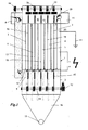
- the illustrated electrostatic precipitator 1 has a box-shaped filter housing 2, which encloses numerous, in several rows vertically extending and mutually parallel, tubular collecting electrodes 3 to 7.
- the gas to be purified flows from an inflow branch 8 to the bottom region 9 of the housing in order to distribute from there to the individual precipitation electrodes 3 to 7, from which it flows out into a head region 10 of the housing to leave this via a discharge port 11.
- the separation between bottom portion 9 and head portion 10 is effected by a lower and upper horizontal partition wall 12, 13, to which the ends of the collecting electrodes 3 to 7 are tightly secured.
- the filter housing 2 merges into a shaft 14 delimited by oblique walls, along the bottom region of which extends a screw conveyor 15, through which ash or dust is discharged, which has dropped down from the precipitation tubes 3 to 7 into the shaft 14.
- each tubular collecting electrode 3 to 7 each extending from a flexible wire spraying electrode 16 to 20, which is releasably connected to the positive pole of a high voltage source of eg 40 kV.
- a high voltage source eg 40 kV.
- Fig. 2 Shown pendulum, not shown insulators suspended contact frame 21, the contact webs 22 in a protruding from the respective collecting electrode 3 to 7 each area on the side of the Sprühelektroden 16 to 20 are applied under its own weight.
- a cable system with attached to a common winding shaft 24 bobbins 25.
- the corresponding negatively charged precipitation electrodes 3 to 7 are connected to a grounding line 23.
- Each spraying electrode 16 to 20 extending through an associated collecting electrode 3 to 7 forms a part of a strand 28 that extends longitudinally in each case into an upper and lower winding drum 26, 27 and can be wound onto it.
- a strand 28 For electrical insulation with respect to the winding drums 26, 27, FIGS this strand 28 an upper and lower, rod-shaped insulating body 29, 30 is provided.
- the lower winding drums 27 are connected to a rotary drive 32 via a common drive shaft 31 to provide, by winding the strands 28 on the winding drums 27, one each above the collecting electrodes 3 to 7 in this strand 28, e.g. As a brush running cleaning body 33 to pull through the associated tubular collecting electrode 3 to 7 and thus to remove adhering to the inner surface of the material so that it drops down into the shaft 14.
- a channel-shaped Isolier Sciences 34 is provided for this laterally on the winding drum 27, which is bounded by an extension 35 of a laterally projecting Drummelnabe 36 .
- a crank arm 37 is provided which extends in the channel direction and thus tangentially away from the drum hub 36 to the outside and at the outer end of an extension pin 39 of the insulating body 30 is attached via a ball joint 40.
- the hub extension 35 and the crank arm 37 are adapted in their length to the insulating body 30 with its extension pin 39 such that upon pivoting of the insulating body 30 into the Isolier Sciencesement 34 of the spray electrode 16 to 20 facing, a joint connection 41 exhibiting end at a lateral drum opening 42nd arrives in such a way that the strand 28 with its spray electrode 16 to 20 can be safely wound onto the winding drum 27.
- the after a certain, empirically determined as optimal time program cleaning process begins with the shutdown of the electrical high voltage. Thereafter, the contact frame 21 is pivoted away from the discharge electrodes 3 to 7. Subsequently, the rotary drive 32 of the lower winding drums 27 is turned on. By the rotation of the respective crank arm 37 pivots downward, so that the rod-shaped insulating body 30 sets in its receptacle 34. The winding drum 27 continuously rotates and winds the spraying electrode 16 to 20 until the cleaning body 33 has been completely drawn through the tubular collecting electrode 3 to 7.
- the respective strand 28 continues via a compensating spring 43 as a steel cable 44, which unwinds from the upper winding drum 26.
- the upper winding drums 26 of a plurality of spray electrodes 16 to 20 are mounted on a common shaft 45, at the end of a cable drum 46 is attached.
- a wound on this cable drum 46 produces a fixed end weight 48 under tension and thus holds on the shaft 45, the tension of the Sprühelektroden 16 to 20 even during the cleaning process upright.
- the tension can be maintained at the spray electrodes 16 to 20 instead of by a weight 48 by a tension spring 50 which is provided in a Schmidtzugseil 51.
- the Jacobyakseil 51 has an extending from the upper cable drum 46 to the mainspring 50 strand 52 and a wound on a Gegenzugtrommel 53 strand 54.
- the winding rotation of this Gegenzugtrommel 53 is transmitted via the same shaft 31 as provided for the winding drum 27 by being mounted on the same shaft 31.
- the only difference is the winding direction, by winding the strand 28 on the winding drum 27 causes a unwinding of the strand 54 of the Schmidtzugtrommel 53 through the described connection on the upper shaft 45.
- a bias of the tension spring 50 permanently determines the tension on the spray electrodes 16 to 20.
- Fig.2 illustrates that a constructed according to the described principle electrostatic precipitator 1 can be extended by adding any further combinations of spray and precipitation electrode both longitudinally and transversely arbitrarily, in order to the given for a particular application in each case flow amount of gas to be purified in a simple or cost-effective manner to be able to adapt.
Landscapes
- Electrostatic Separation (AREA)
Abstract
Description
Die Erfindung betrifft einen Elektrofilter für die Abscheidung von Staubpartikeln aus einem Gasstrom, mit mindestens einer, in einem vom Gas durchströmten Gehäuse befestigten Niederschlagselektrode und mit einer ihr mit Abstand parallel zugeordneten, unter Zugspannung gestreckt gehaltenen Sprühelektrode sowie mit periodisch wirkenden Mitteln zur Reinigung der Niederschlagselektrode.The invention relates to an electrostatic precipitator for the separation of dust particles from a gas stream, with at least one attached in a gas flowed through the housing precipitation electrode and with a parallel spaced by her, stretched under tension held spray electrode and periodically acting means for cleaning the collecting electrode.
Bei einem durch die
Durch die
Der Erfindung liegt die Aufgabe zugrunde, einen Elektrofilter der genannten Art zu finden, der bei kompakter und kostengünstig realisierbarer Bauweise bei hoher Zuverlässigkeit eine gute Reinigung der Niederschlagselektroden ermöglicht. Die Lösung dieser Aufgabe erfolgt erfindungsgemäß aufgrund der Merkmale des Patentanspruchs 1. Vorteilhafte Ausgestaltungen der Erfindung sind Gegenstand der abhängigen Patentansprüche und der folgenden Beschreibung anhand der Zeichnungen zu entnehmen. Es zeigt:
-
Fig.1 einen Querschnitt durch einen erfindungsgemäßen Elektrofilter in schematischer Darstellung, -
Fig.2 eine Ansicht der Unterseite des Elektrofilters nachFig.1 im Bereich seiner Wickeltrommeln, -
Fig.3 eine schematische Gesamtdarstellung der Mechanik zur Ausführung der Reinigungsbewegung eines eine Sprühelektrode tragenden Stranges eines Elektrofilters nachFig.1 , mit einer durch Strichlinien veranschaulichten Variante für die Aufrechterhaltung einer Zugspannung an solchen Strängen, -
Fig.4 eine perspektivische Darstellung einer Wickeltrommel des Elektrofilters nachFig.1 und -
Fig.5 eine Aufsicht auf die Wickeltrommel nachFig. 4 .
-
Fig.1 a cross section through an electrostatic filter according to the invention in a schematic representation, -
Fig.2 a view of the bottom of the electrostatic filter afterFig.1 in the area of his winding drums, -
Figure 3 a schematic overall view of the mechanism for performing the cleaning movement of a spray electrode carrying strand of an electrostatic filter according toFig.1 , with a variant illustrated by dashed lines for the maintenance of a tensile stress on such strands, -
Figure 4 a perspective view of a winding drum of the electrostatic filter afterFig.1 and -
Figure 5 a view of the winding drum afterFig. 4 ,
Der dargestellte Elektrofilter 1 hat ein kastenförmiges Filtergehäuse 2, das zahlreiche in mehreren Reihen vertikal verlaufende und parallel zueinander angeordnete, rohrförmige Niederschlagselektroden 3 bis 7 umschliesst. Das zu reinigende, beispielsweise als Abgas von einer Anlage zur Holzverbrennung kommende Gas strömt von einem Zuströmstutzen 8 zum Bodenbereich 9 des Gehäuses, um sich von dort aus auf die einzelnen Niederschlagselektroden 3 bis 7 zu verteilen, aus denen es in einen Kopfbereich 10 des Gehäuses ausströmt, um diesen über einen Ausströmstutzen 11 zu verlassen. Die Abtrennung zwischen Bodenbereich 9 und Kopfbereich 10 erfolgt durch eine untere und obere horizontale Trennwand 12, 13, an den die Enden der Niederschlagselektroden 3 bis 7 dicht befestigt sind. Nach unten geht das Filtergehäuse 2 in einen durch schräge Wände begrenzten Schacht 14 über, entlang dessen Bodenbereich sich ein Schneckenförderer 15 erstreckt, durch den Asche oder Staub ausgetragen wird, die aus den Niederschlagsrohren 3 bis 7 nach unten in den Schacht 14 abgefallen ist.The illustrated
Entlang der Achse jeder rohrförmigen Niederschlagselektrode 3 bis 7 erstreckt sich jeweils eine aus einem biegsamen Draht bestehende Sprühelektrode 16 bis 20, die mit dem positiven Pol einer Hochspannungsquelle von z.B. 40 kV lösbar verbunden ist. Hierzu dient ein in
Jede sich durch eine zugehörige Niederschlagselektrode 3 bis 7 erstreckende Sprühelektrode 16 bis 20 bildet einen Teil eines in Längsrichtung zu jeweils einer oberen und unteren Wickeltrommel 26, 27 und auf diese aufwickelbar weiter verlaufenden Stranges 28. Zur elektrischen Isolation gegenüber den Wickeltrommeln 26, 27 sind in diesem Strang 28 ein oberer und unterer, stangenförmiger Isolierkörper 29, 30 vorgesehen.Each spraying
Die unteren Wickeltrommeln 27 sind über eine gemeinsame Antriebswelle 31 mit einem Drehantrieb 32 verbunden, um durch Aufwickeln der Stränge 28 auf die Wickeltrommeln 27 jeweils einen oberhalb der Niederschlagselektroden 3 bis 7 in diesem Strang 28 vorgesehenen, z.B. als Bürste ausgeführten Reinigungskörper 33, durch die zugehörige rohrförmige Niederschlagselektrode 3 bis 7 hindurch zu ziehen und somit an dessen Innenfläche haften gebliebenes Material zu entfernen, so dass es nach unten in den Schacht 14 abfällt.The lower
Um das Aufwickeln der Stränge 28 auf die Wickeltrommeln 27 trotz des am jeweiligen Strang vorgesehenen, stabförmigen Isolierkörpers 30 zuverlässig zu ermöglichen, ist für diesen seitlich an der Wickeltrommel 27 eine kanalförmige Isolierkörperaufnahme 34 vorgesehen, die von einem Fortsatz 35 einer seitlich überstehenden Trommelnabe 36 begrenzt ist. Ausserdem ist ein Kurbelarm 37 vorgesehen, der sich in Kanalrichtung und damit tangential von der Trommelnabe 36 weg nach aussen erstreckt und an dessen äusseren Ende ein Verlängerungszapfen 39 des Isolierkörpers 30 über ein Kugelgelenk 40 befestigt ist. Dabei sind der Nabenfortsatz 35 und der Kurbelarm 37 in ihrer Länge dem Isolierkörper 30 mit seinem Verlängerungszapfen 39 derart angepasst, dass beim Einschwenken des Isolierkörpers 30 in die Isolierkörperaufnahme 34 sein der Sprühelektrode 16 bis 20 zugekehrtes, eine Gelenkverbindung 41 aufweisendes Ende an einer seitlichen Trommelöffnung 42 derart zur Anlage gelangt, dass der Strang 28 mit seiner Sprühelektrode 16 bis 20 sich sicher auf die Wickeltrommel 27 aufwickeln lässt.In order to allow the winding of the
Der nach einem bestimmten, empirisch als optimal ermittelten Zeitprogramm erfolgende Reinigungsvorgang beginnt mit der Abschaltung der elektrischen Hochspannung. Danach wird der Kontaktrahmen 21 von den Sprühelektroden 3 bis 7 weggeschwenkt. Anschliessend wird der Drehantrieb 32 der unteren Wickeltrommeln 27 eingeschaltet. Durch deren Drehung schwenkt der jeweilige Kurbelarm 37 nach unten, so dass sich der stabförmige Isolierkörper 30 in seine Aufnahme 34 legt. Die Wickeltrommel 27 dreht sich kontinuierlich weiter und wickelt die Sprühelektrode 16 bis 20 so weit auf, bis der Reinigungskörper 33 vollständig durch die rohrförmige Niederschlagselektrode 3 bis 7 gezogen worden ist.The after a certain, empirically determined as optimal time program cleaning process begins with the shutdown of the electrical high voltage. Thereafter, the
Am oberen, sich an den Reinigungskörper 33 anschliessenden Ende setzt sich der jeweilige Strang 28 über eine Ausgleichsfeder 43 als Stahlseil 44 fort, das sich dabei von der oberen Wickeltrommel 26 abwickelt.At the upper end adjoining the
Die oberen Wickeltrommeln 26 von mehreren Sprühelektroden 16 bis 20 sind auf einer gemeinsamen Welle 45 befestigt, an deren Ende eine Seilzugtrommel 46 befestigt ist. Ein auf dieser Seilzugtrommel 46 aufgewickeltes Gegenzugseil 47 wird durch ein endseitig befestigtes Gewicht 48 unter Spannung gehalten und hält somit über die Welle 45 die Zugspannung der Sprühelektroden 16 bis 20 auch während des Reinigungsvorganges aufrecht.The upper
Wie in
Die Darstellung der
Es versteht sich, dass die anhand eines Ausführungsbeispieles mit rohrförmigen Niederschlagselektroden beschriebene Erfindung auch für Elektrofilter mit anders, z.B. plattenförmig ausgeführten Elektroden anwendbar ist, mit entsprechender Anpassung der Querschnittsform der vorzugsweise aufwickelbaren positiven Elektrode an die Form der Niederschlagselektrode und auch entsprechender Anpassung der Querschnittsform einer angekoppelten Reinigungsvorrichtung.It is understood that the invention described with reference to an embodiment with tubular collecting electrodes also for electrostatic precipitators with different, e.g. plate-shaped running electrodes is applicable, with appropriate adaptation of the cross-sectional shape of the preferably wound positive electrode to the shape of the collecting electrode and also corresponding adjustment of the cross-sectional shape of a coupled cleaning device.
Claims (9)
Applications Claiming Priority (1)
| Application Number | Priority Date | Filing Date | Title |
|---|---|---|---|
| CH18422007 | 2007-11-27 |
Publications (3)
| Publication Number | Publication Date |
|---|---|
| EP2065094A2 true EP2065094A2 (en) | 2009-06-03 |
| EP2065094A3 EP2065094A3 (en) | 2013-04-24 |
| EP2065094B1 EP2065094B1 (en) | 2016-08-17 |
Family
ID=56372691
Family Applications (1)
| Application Number | Title | Priority Date | Filing Date |
|---|---|---|---|
| EP08405265.3A Active EP2065094B1 (en) | 2007-11-27 | 2008-10-22 | Electrostatic precipitator |
Country Status (2)
| Country | Link |
|---|---|
| EP (1) | EP2065094B1 (en) |
| DK (1) | DK2065094T3 (en) |
Cited By (1)
| Publication number | Priority date | Publication date | Assignee | Title |
|---|---|---|---|---|
| CN105618732A (en) * | 2015-12-29 | 2016-06-01 | 北京钢研高纳科技股份有限公司 | Preparation method of high-temperature alloy powder |
Citations (2)
| Publication number | Priority date | Publication date | Assignee | Title |
|---|---|---|---|---|
| EP0397208A2 (en) | 1989-05-12 | 1990-11-14 | FRITZ EGGER GESELLSCHAFT m.b.H. | Electrostatic precipitator for gas cleaning |
| EP1050341A2 (en) | 1999-05-03 | 2000-11-08 | Paul Forsthuber | Tubular electrofilter with movable electrodes |
Family Cites Families (5)
| Publication number | Priority date | Publication date | Assignee | Title |
|---|---|---|---|---|
| US1478798A (en) * | 1919-05-27 | 1923-12-25 | Int Precipitation Co | Apparatus for electrical treatment of gases |
| DE490951C (en) * | 1924-03-25 | 1930-04-25 | Siemens Schuckertwerke Akt Ges | Device for cleaning tubular collecting electrodes of electrical gas cleaning systems with scrapers |
| US1794074A (en) * | 1926-06-19 | 1931-02-24 | Res Corp Of New York | Precipitator cleaning device |
| FR2655570B1 (en) * | 1989-12-12 | 1992-06-19 | Commissariat Energie Atomique | ELECTROSTATIC FILTER PROVIDED WITH A CLEANING SYSTEM. |
| DE202007004263U1 (en) * | 2007-02-16 | 2007-07-05 | Otto Spanner Gmbh | Electric filter for cleaning flue gas, has electrode arrangement comprising spraying electrode and precipitation electrode, where one of electrodes is provided with electrically conducting coating on surface facing filter space |
-
2008
- 2008-10-22 DK DK08405265.3T patent/DK2065094T3/en active
- 2008-10-22 EP EP08405265.3A patent/EP2065094B1/en active Active
Patent Citations (2)
| Publication number | Priority date | Publication date | Assignee | Title |
|---|---|---|---|---|
| EP0397208A2 (en) | 1989-05-12 | 1990-11-14 | FRITZ EGGER GESELLSCHAFT m.b.H. | Electrostatic precipitator for gas cleaning |
| EP1050341A2 (en) | 1999-05-03 | 2000-11-08 | Paul Forsthuber | Tubular electrofilter with movable electrodes |
Cited By (2)
| Publication number | Priority date | Publication date | Assignee | Title |
|---|---|---|---|---|
| CN105618732A (en) * | 2015-12-29 | 2016-06-01 | 北京钢研高纳科技股份有限公司 | Preparation method of high-temperature alloy powder |
| CN105618732B (en) * | 2015-12-29 | 2017-07-25 | 北京钢研高纳科技股份有限公司 | A kind of preparation method of superalloy powder |
Also Published As
| Publication number | Publication date |
|---|---|
| EP2065094A3 (en) | 2013-04-24 |
| DK2065094T3 (en) | 2016-11-28 |
| EP2065094B1 (en) | 2016-08-17 |
Similar Documents
| Publication | Publication Date | Title |
|---|---|---|
| EP1958696A2 (en) | Electrofilter | |
| DE3626002C2 (en) | ||
| WO2007006259A1 (en) | Cleaning installation for towers of wind-energy installations | |
| DE102011052946A1 (en) | Electrical separation device for filtering particles from gas flow by electrostatic separation, has inlet and suction openings that are arranged so that gas flows to collector through flow channel along wave crest extending direction | |
| EP2065094A2 (en) | Electrostatic precipitator | |
| DE102006009765B4 (en) | Tube electrostatic precipitator | |
| EP3461330A1 (en) | Strainer arrangement for straining viscous or pasty substances | |
| DE102008018207B3 (en) | Chimney system with electric dust filter | |
| DE2106048A1 (en) | Device for collecting discrete materials, in particular for the production of fiberglass packages | |
| DE3622699A1 (en) | ELECTROSTATIC DUST SEPARATOR | |
| EP0768430A1 (en) | Arrangement for collecting debris from fluid flowing in a channel | |
| EP2451582B1 (en) | Electrostatic filter | |
| DE2810931C2 (en) | Conveyor belt cleaning device | |
| AT506397B1 (en) | SEPARATION DEVICE FOR PARTICLES | |
| EP3153345B1 (en) | Arrangement for holding a supporting rope and wire in electric railway overhead line | |
| DE102015114499A1 (en) | Device for stripping material from the lower strand of the conveyor belt of a belt conveyor | |
| DE6912552U (en) | ELECTRIC SEPARATOR. | |
| EP3676125A1 (en) | Overhead line system | |
| DE4227556C2 (en) | Cleaning device for bar rakes | |
| DE490951C (en) | Device for cleaning tubular collecting electrodes of electrical gas cleaning systems with scrapers | |
| DE202006003340U1 (en) | Tubular electrofilter for cleaning gases has a holder for the electrodes with the spray electrode still being freely supported within the deposition electrode | |
| DE2919707C2 (en) | Device for the automatic maintenance of a given tension force in a contact wire or suspension cable of overhead lines of electric railways | |
| DE964436C (en) | Blow-off system, especially for textile machines | |
| EP1545743B1 (en) | Flue gas washer with a supporting construction for spray pipes | |
| DE102017114638B4 (en) | Electrostatic precipitator and method for the electrostatic precipitation of substances from an exhaust gas stream |
Legal Events
| Date | Code | Title | Description |
|---|---|---|---|
| PUAI | Public reference made under article 153(3) epc to a published international application that has entered the european phase |
Free format text: ORIGINAL CODE: 0009012 |
|
| AK | Designated contracting states |
Kind code of ref document: A2 Designated state(s): AT BE BG CH CY CZ DE DK EE ES FI FR GB GR HR HU IE IS IT LI LT LU LV MC MT NL NO PL PT RO SE SI SK TR |
|
| AX | Request for extension of the european patent |
Extension state: AL BA MK RS |
|
| RAP1 | Party data changed (applicant data changed or rights of an application transferred) |
Owner name: MEISTER UMWELT TECHNOLOGIE AG |
|
| PUAL | Search report despatched |
Free format text: ORIGINAL CODE: 0009013 |
|
| AK | Designated contracting states |
Kind code of ref document: A3 Designated state(s): AT BE BG CH CY CZ DE DK EE ES FI FR GB GR HR HU IE IS IT LI LT LU LV MC MT NL NO PL PT RO SE SI SK TR |
|
| AX | Request for extension of the european patent |
Extension state: AL BA MK RS |
|
| RIC1 | Information provided on ipc code assigned before grant |
Ipc: B03C 3/74 20060101AFI20130320BHEP Ipc: B03C 3/06 20060101ALI20130320BHEP |
|
| 17P | Request for examination filed |
Effective date: 20131024 |
|
| RBV | Designated contracting states (corrected) |
Designated state(s): AT BE BG CH CY CZ DE DK EE ES FI FR GB GR HR HU IE IS IT LI LT LU LV MC MT NL NO PL PT RO SE SI SK TR |
|
| AKX | Designation fees paid |
Designated state(s): AT BE BG CH CY CZ DE DK EE ES FI FR GB GR HR HU IE IS IT LI LT LU LV MC MT NL NO PL PT RO SE SI SK TR |
|
| 17Q | First examination report despatched |
Effective date: 20140414 |
|
| REG | Reference to a national code |
Ref country code: DE Ref legal event code: R079 Ref document number: 502008014524 Country of ref document: DE Free format text: PREVIOUS MAIN CLASS: B03C0003740000 Ipc: B03C0003410000 |
|
| GRAP | Despatch of communication of intention to grant a patent |
Free format text: ORIGINAL CODE: EPIDOSNIGR1 |
|
| GRAS | Grant fee paid |
Free format text: ORIGINAL CODE: EPIDOSNIGR3 |
|
| RIC1 | Information provided on ipc code assigned before grant |
Ipc: B03C 3/74 20060101ALI20160609BHEP Ipc: B03C 3/06 20060101ALI20160609BHEP Ipc: B03C 3/41 20060101AFI20160609BHEP Ipc: B03C 3/86 20060101ALI20160609BHEP |
|
| GRAA | (expected) grant |
Free format text: ORIGINAL CODE: 0009210 |
|
| INTG | Intention to grant announced |
Effective date: 20160622 |
|
| AK | Designated contracting states |
Kind code of ref document: B1 Designated state(s): AT BE BG CH CY CZ DE DK EE ES FI FR GB GR HR HU IE IS IT LI LT LU LV MC MT NL NO PL PT RO SE SI SK TR |
|
| REG | Reference to a national code |
Ref country code: GB Ref legal event code: FG4D Free format text: NOT ENGLISH |
|
| REG | Reference to a national code |
Ref country code: CH Ref legal event code: EP |
|
| REG | Reference to a national code |
Ref country code: IE Ref legal event code: FG4D Free format text: LANGUAGE OF EP DOCUMENT: GERMAN |
|
| REG | Reference to a national code |
Ref country code: AT Ref legal event code: REF Ref document number: 820542 Country of ref document: AT Kind code of ref document: T Effective date: 20160915 |
|
| REG | Reference to a national code |
Ref country code: DE Ref legal event code: R096 Ref document number: 502008014524 Country of ref document: DE |
|
| REG | Reference to a national code |
Ref country code: CH Ref legal event code: NV Representative=s name: DIPL.-ING. HORST QUEHL PATENTANWALT, CH |
|
| REG | Reference to a national code |
Ref country code: FR Ref legal event code: PLFP Year of fee payment: 9 |
|
| REG | Reference to a national code |
Ref country code: NL Ref legal event code: FP |
|
| REG | Reference to a national code |
Ref country code: SE Ref legal event code: TRGR |
|
| REG | Reference to a national code |
Ref country code: DK Ref legal event code: T3 Effective date: 20161121 |
|
| REG | Reference to a national code |
Ref country code: NO Ref legal event code: T2 Effective date: 20160817 Ref country code: LT Ref legal event code: MG4D |
|
| PG25 | Lapsed in a contracting state [announced via postgrant information from national office to epo] |
Ref country code: LT Free format text: LAPSE BECAUSE OF FAILURE TO SUBMIT A TRANSLATION OF THE DESCRIPTION OR TO PAY THE FEE WITHIN THE PRESCRIBED TIME-LIMIT Effective date: 20160817 Ref country code: FI Free format text: LAPSE BECAUSE OF FAILURE TO SUBMIT A TRANSLATION OF THE DESCRIPTION OR TO PAY THE FEE WITHIN THE PRESCRIBED TIME-LIMIT Effective date: 20160817 Ref country code: HR Free format text: LAPSE BECAUSE OF FAILURE TO SUBMIT A TRANSLATION OF THE DESCRIPTION OR TO PAY THE FEE WITHIN THE PRESCRIBED TIME-LIMIT Effective date: 20160817 |
|
| PG25 | Lapsed in a contracting state [announced via postgrant information from national office to epo] |
Ref country code: GR Free format text: LAPSE BECAUSE OF FAILURE TO SUBMIT A TRANSLATION OF THE DESCRIPTION OR TO PAY THE FEE WITHIN THE PRESCRIBED TIME-LIMIT Effective date: 20161118 Ref country code: PT Free format text: LAPSE BECAUSE OF FAILURE TO SUBMIT A TRANSLATION OF THE DESCRIPTION OR TO PAY THE FEE WITHIN THE PRESCRIBED TIME-LIMIT Effective date: 20161219 Ref country code: ES Free format text: LAPSE BECAUSE OF FAILURE TO SUBMIT A TRANSLATION OF THE DESCRIPTION OR TO PAY THE FEE WITHIN THE PRESCRIBED TIME-LIMIT Effective date: 20160817 Ref country code: LV Free format text: LAPSE BECAUSE OF FAILURE TO SUBMIT A TRANSLATION OF THE DESCRIPTION OR TO PAY THE FEE WITHIN THE PRESCRIBED TIME-LIMIT Effective date: 20160817 Ref country code: PL Free format text: LAPSE BECAUSE OF FAILURE TO SUBMIT A TRANSLATION OF THE DESCRIPTION OR TO PAY THE FEE WITHIN THE PRESCRIBED TIME-LIMIT Effective date: 20160817 |
|
| PG25 | Lapsed in a contracting state [announced via postgrant information from national office to epo] |
Ref country code: RO Free format text: LAPSE BECAUSE OF FAILURE TO SUBMIT A TRANSLATION OF THE DESCRIPTION OR TO PAY THE FEE WITHIN THE PRESCRIBED TIME-LIMIT Effective date: 20160817 Ref country code: EE Free format text: LAPSE BECAUSE OF FAILURE TO SUBMIT A TRANSLATION OF THE DESCRIPTION OR TO PAY THE FEE WITHIN THE PRESCRIBED TIME-LIMIT Effective date: 20160817 |
|
| REG | Reference to a national code |
Ref country code: DE Ref legal event code: R097 Ref document number: 502008014524 Country of ref document: DE |
|
| PG25 | Lapsed in a contracting state [announced via postgrant information from national office to epo] |
Ref country code: SK Free format text: LAPSE BECAUSE OF FAILURE TO SUBMIT A TRANSLATION OF THE DESCRIPTION OR TO PAY THE FEE WITHIN THE PRESCRIBED TIME-LIMIT Effective date: 20160817 Ref country code: BG Free format text: LAPSE BECAUSE OF FAILURE TO SUBMIT A TRANSLATION OF THE DESCRIPTION OR TO PAY THE FEE WITHIN THE PRESCRIBED TIME-LIMIT Effective date: 20161117 Ref country code: CZ Free format text: LAPSE BECAUSE OF FAILURE TO SUBMIT A TRANSLATION OF THE DESCRIPTION OR TO PAY THE FEE WITHIN THE PRESCRIBED TIME-LIMIT Effective date: 20160817 |
|
| PLBE | No opposition filed within time limit |
Free format text: ORIGINAL CODE: 0009261 |
|
| STAA | Information on the status of an ep patent application or granted ep patent |
Free format text: STATUS: NO OPPOSITION FILED WITHIN TIME LIMIT |
|
| 26N | No opposition filed |
Effective date: 20170518 |
|
| REG | Reference to a national code |
Ref country code: IE Ref legal event code: MM4A |
|
| PG25 | Lapsed in a contracting state [announced via postgrant information from national office to epo] |
Ref country code: LU Free format text: LAPSE BECAUSE OF NON-PAYMENT OF DUE FEES Effective date: 20161022 Ref country code: SI Free format text: LAPSE BECAUSE OF FAILURE TO SUBMIT A TRANSLATION OF THE DESCRIPTION OR TO PAY THE FEE WITHIN THE PRESCRIBED TIME-LIMIT Effective date: 20160817 |
|
| REG | Reference to a national code |
Ref country code: FR Ref legal event code: PLFP Year of fee payment: 10 |
|
| PG25 | Lapsed in a contracting state [announced via postgrant information from national office to epo] |
Ref country code: IE Free format text: LAPSE BECAUSE OF NON-PAYMENT OF DUE FEES Effective date: 20161022 |
|
| PG25 | Lapsed in a contracting state [announced via postgrant information from national office to epo] |
Ref country code: CY Free format text: LAPSE BECAUSE OF FAILURE TO SUBMIT A TRANSLATION OF THE DESCRIPTION OR TO PAY THE FEE WITHIN THE PRESCRIBED TIME-LIMIT Effective date: 20160817 Ref country code: HU Free format text: LAPSE BECAUSE OF FAILURE TO SUBMIT A TRANSLATION OF THE DESCRIPTION OR TO PAY THE FEE WITHIN THE PRESCRIBED TIME-LIMIT; INVALID AB INITIO Effective date: 20081022 |
|
| PG25 | Lapsed in a contracting state [announced via postgrant information from national office to epo] |
Ref country code: MT Free format text: LAPSE BECAUSE OF FAILURE TO SUBMIT A TRANSLATION OF THE DESCRIPTION OR TO PAY THE FEE WITHIN THE PRESCRIBED TIME-LIMIT Effective date: 20160817 Ref country code: TR Free format text: LAPSE BECAUSE OF FAILURE TO SUBMIT A TRANSLATION OF THE DESCRIPTION OR TO PAY THE FEE WITHIN THE PRESCRIBED TIME-LIMIT Effective date: 20160817 Ref country code: IS Free format text: LAPSE BECAUSE OF FAILURE TO SUBMIT A TRANSLATION OF THE DESCRIPTION OR TO PAY THE FEE WITHIN THE PRESCRIBED TIME-LIMIT Effective date: 20160817 Ref country code: MC Free format text: LAPSE BECAUSE OF FAILURE TO SUBMIT A TRANSLATION OF THE DESCRIPTION OR TO PAY THE FEE WITHIN THE PRESCRIBED TIME-LIMIT Effective date: 20160817 |
|
| REG | Reference to a national code |
Ref country code: FR Ref legal event code: PLFP Year of fee payment: 11 |
|
| PGFP | Annual fee paid to national office [announced via postgrant information from national office to epo] |
Ref country code: NL Payment date: 20231019 Year of fee payment: 16 |
|
| PGFP | Annual fee paid to national office [announced via postgrant information from national office to epo] |
Ref country code: GB Payment date: 20231020 Year of fee payment: 16 |
|
| PGFP | Annual fee paid to national office [announced via postgrant information from national office to epo] |
Ref country code: SE Payment date: 20231019 Year of fee payment: 16 Ref country code: NO Payment date: 20231025 Year of fee payment: 16 Ref country code: IT Payment date: 20231026 Year of fee payment: 16 Ref country code: FR Payment date: 20231024 Year of fee payment: 16 Ref country code: DK Payment date: 20231024 Year of fee payment: 16 Ref country code: DE Payment date: 20231020 Year of fee payment: 16 Ref country code: CH Payment date: 20231101 Year of fee payment: 16 Ref country code: AT Payment date: 20231020 Year of fee payment: 16 |
|
| PGFP | Annual fee paid to national office [announced via postgrant information from national office to epo] |
Ref country code: BE Payment date: 20231019 Year of fee payment: 16 |