EP2064591B1 - Photographic apparatus - Google Patents
Photographic apparatus Download PDFInfo
- Publication number
- EP2064591B1 EP2064591B1 EP07804467A EP07804467A EP2064591B1 EP 2064591 B1 EP2064591 B1 EP 2064591B1 EP 07804467 A EP07804467 A EP 07804467A EP 07804467 A EP07804467 A EP 07804467A EP 2064591 B1 EP2064591 B1 EP 2064591B1
- Authority
- EP
- European Patent Office
- Prior art keywords
- enclosure
- light
- background
- illuminating wall
- panels
- Prior art date
- Legal status (The legal status is an assumption and is not a legal conclusion. Google has not performed a legal analysis and makes no representation as to the accuracy of the status listed.)
- Active
Links
Images


Classifications
-
- G—PHYSICS
- G03—PHOTOGRAPHY; CINEMATOGRAPHY; ANALOGOUS TECHNIQUES USING WAVES OTHER THAN OPTICAL WAVES; ELECTROGRAPHY; HOLOGRAPHY
- G03B—APPARATUS OR ARRANGEMENTS FOR TAKING PHOTOGRAPHS OR FOR PROJECTING OR VIEWING THEM; APPARATUS OR ARRANGEMENTS EMPLOYING ANALOGOUS TECHNIQUES USING WAVES OTHER THAN OPTICAL WAVES; ACCESSORIES THEREFOR
- G03B15/00—Special procedures for taking photographs; Apparatus therefor
- G03B15/02—Illuminating scene
-
- F—MECHANICAL ENGINEERING; LIGHTING; HEATING; WEAPONS; BLASTING
- F21—LIGHTING
- F21V—FUNCTIONAL FEATURES OR DETAILS OF LIGHTING DEVICES OR SYSTEMS THEREOF; STRUCTURAL COMBINATIONS OF LIGHTING DEVICES WITH OTHER ARTICLES, NOT OTHERWISE PROVIDED FOR
- F21V11/00—Screens not covered by groups F21V1/00, F21V3/00, F21V7/00 or F21V9/00
-
- G—PHYSICS
- G03—PHOTOGRAPHY; CINEMATOGRAPHY; ANALOGOUS TECHNIQUES USING WAVES OTHER THAN OPTICAL WAVES; ELECTROGRAPHY; HOLOGRAPHY
- G03B—APPARATUS OR ARRANGEMENTS FOR TAKING PHOTOGRAPHS OR FOR PROJECTING OR VIEWING THEM; APPARATUS OR ARRANGEMENTS EMPLOYING ANALOGOUS TECHNIQUES USING WAVES OTHER THAN OPTICAL WAVES; ACCESSORIES THEREFOR
- G03B15/00—Special procedures for taking photographs; Apparatus therefor
- G03B15/02—Illuminating scene
- G03B15/06—Special arrangements of screening, diffusing, or reflecting devices, e.g. in studio
Definitions
- This invention relates to photographic apparatus, and in particular photographic apparatus for providing an illuminated background for an object being photographed.
- Photographers often wish to photograph objects against a featureless background, and typically use either one or more rigid panels, or one or more sheets of flexible material, to provide such a background. It is also known to provide a background that is illuminated to a sufficient extent for the background to be over-exposed in the photograph, and hence appear as an entirely featureless pure white background in the photograph.
- a disadvantage associated with conventional apparatus is that the rigid panels and/or the sheets of flexible material that form the background, and also the plurality of light sources normally required to illuminate the background, are time-consuming to erect and arrange in such a way that the background is illuminated to a sufficient degree across its entire surface. Furthermore, since the background must be illuminated without any shadows being formed on its surface, the object being photographed needs to be situated a considerable distance in front of the background, which is clearly inconvenient if space is limited.
- Apparatus has been developed that comprises a stand having a transparent plastics support wall with an upper surface that is generally concave and hence defines both a support surface and a background for the object being photographed.
- the apparatus further includes a light source that directly illuminates the underside of the transparent support wall, and hence illuminates the support surface and the background for the object being photographed.
- a major disadvantage associated with this apparatus is that the stand is necessarily rather large and rigid in form, and hence not readily transportable.
- this apparatus is generally not suitable for photographing larger objects, such as people or cars.
- a method of photographing an object which method comprises the steps of
- a collapsible background unit for use in association with a light source and a camera for photographing an object
- the collapsible background unit comprising an enclosure with an illuminating wall that is translucent, the arrangement being such that when light from a light source is directed into the interior of the enclosure the illuminating wall transmits at least some of said light to the exterior of the enclosure, such that the illuminating wall, or an additional translucent component interposed between the illuminating wall and the object, constitutes a background for the object
- the collapsible background unit includes first and second panels, each panel comprising a sheet of flexible material mounted in a resilient frame and being adapted to maintain its shape during normal use, the first and second panels being connected by a web of flexible material that extends between the frames of the first and second panels, and the connecting web being held in tension by a plurality of removable support struts that extend between the panels, the support struts being situated externally of the connecting web.
- apparatus for photographing an object comprising a camera, a collapsible background unit according to the second aspect, and a light source arranged relative to the background unit so that light from the light source is directed into the interior of the enclosure, the illuminating wall being adapted to transmit at least some of said light to the exterior of the enclosure, and the camera and the object being arranged externally of the enclosure such that the illuminating wall, or an additional translucent component interposed between the illuminating wall and the object, constitutes a background for the object.
- the method and apparatus for photographing an object according to the invention are advantageous principally because they enable a uniformly illuminated background to be achieved with only simple components, including in most cases a single light source, that require much less preparation and arrangement than prior art apparatus. Furthermore, the present invention enables the object being photographed to be situated much closer to the background than with prior art apparatus, without it being necessary for the light source to be located directly below the object.
- a background for the object is meant all matter other than the object that is visible in the photograph of that object.
- the background may therefore extend to the front and rear of the object, as well as above, below and to the side of the object.
- the light transmitted through the illuminating wall that forms the background for the object is of sufficient intensity relative to the exposure settings of the camera for the transmitted light to be over-exposed in the photograph, and hence to appear white and featureless in the photograph.
- the background unit is preferably adapted to be self-supporting, and hence be positionable upon a suitable surface, such as a floor, in a free-standing configuration during use.
- the background unit is positionable upon a suitable surface in an upright configuration, in which the illuminating wall is capable of constituting a background for the object.
- the background unit is reducible in size, most preferably by at least 75%, along at least one dimension.
- the background unit comprises two panels, and the connecting web preferably extends between the perimeters of the two panels.
- the support struts are preferably removable, and are preferably adapted at each end to engage a frame of a panel.
- one of the panels includes the illuminating wall.
- the illuminating wall preferably has a uniform partial transparency to visible light, and preferably acts to diffuse visible light that is transmitted therethrough.
- the illuminating wall preferably therefore has a uniformly illuminated exterior surface.
- the illuminating wall preferably comprises a sheet of flexible material, and is most preferably held in tension in order to remove any creases or wrinkles.
- the illuminating wall is formed of a woven or knitted fabric.
- the illuminating wall is preferably formed of an elastic material, and hence is preferably formed of a knitted fabric.
- the illuminating wall preferably has a smooth external surface, and therefore preferably includes a plastics coating on its external surface.
- the plastics coating is preferably smooth in form, and is preferably of white colouration.
- that component also preferably has a uniform partial transparency to visible light, and preferably acts to diffuse visible light that is transmitted therethrough.
- the separate translucent component preferably therefore has a uniformly illuminated surface that faces the camera.
- the enclosure is preferably adapted to receive light from the light source through an opening in a wall of the enclosure
- the enclosure may include a translucent wall, in addition to the illuminating wall, through which light from the light source may be directed into the interior of the enclosure.
- the translucent wall may be provided along with, or in the place of, the opening.
- the translucent wall acts to diffuse light transmitted therethrough, and has a light transmittance that is less than that of the illuminating wall.
- the connecting web is translucent, but to a significantly less extent than the illuminating wall.
- the interior surface of the enclosure is preferably adapted to reflect at least a portion of the light directed into the interior of the enclosure by the light source, so that said light is reflected about the interior of the enclosure before being transmitted through the illuminating wall.
- a major part of the interior surface of the enclosure is preferably adapted to reflect light incident thereon, and is preferably of white colouration.
- the camera is preferably a conventional photographic camera, such as a digital photographic camera. Most preferably, however, the camera is capable of indicating to the photographer when the light intensity of the background is sufficient relative to the exposure settings of the camera for the background to be over-exposed in the photograph. For instance, the camera may be capable of creating an exposure histogram. In order to obtain correct exposure of the object in the photograph, additional light sources are preferably provided for lighting the front surfaces of the object.
- an additional background unit may be positioned to one side of the object, out of sight of the camera, and an additional light source may be arranged so that light is directed into the interior of the additional background unit, at least some of said light is transmitted to the exterior of the enclosure through the illuminating wall, and at least some of said transmitted light illuminates the object.
- the additional background unit may therefore be used as free-standing light-diffusing apparatus.
- the illuminating wall is preferably held in tension by a frame so as to form one of the panels of the background unit.
- the frame is preferably resilient, and preferably comprises a fabric tube to which the illuminating wall is fixed and a resilient hoop accommodated within the fabric tube.
- the illuminating enclosure comprises first and second panels, with the first panel including the illuminating wall.
- the connecting web preferably extends between the frames of the two panels.
- the connecting web may be formed of any suitably flexible material, such as a woven or knitted fabric or a plastics material such as polyvinylchloride (PVC).
- PVC polyvinylchloride
- the connecting web is formed of a knitted fabric, which may include a plastic coating on its exterior surface.
- the illuminating enclosure is preferably defined by the first and second panels and the connecting web, and the opening in the illuminating enclosure is preferably formed in the connecting web.
- Each support strut may include a notch at each end that is adapted to receive an edge of the frame of a panel.
- the ends of each support strut may be adapted to be received within recesses in the frames of the panels.
- the background unit includes at least four support struts that are spaced generally equidistantly about the perimeter of the enclosure.
- the object is positioned directly in front of the illuminating wall, externally of the enclosure, such that the illuminating wall forms a background for the object being photographed.
- the background unit preferably rests upon adjacent edges of the two panels, and hence is free-standing in an upright configuration.
- the opening is preferably situated so that the light source can be readily positioned to direct light through the opening, but the opening is most conveniently situated on one side of the background unit.
- the object or objects are preferably positioned within 2m, and most preferably within 1 m, of the illuminating wall.
- the illuminating wall preferably has sufficiently large dimensions for the illuminating wall to constitute the entire background for the object, and hence the illuminating wall preferably has a length and/or width of at least 1.2m.
- the apparatus is preferably arranged so that the light intensity of the background is sufficient relative to the exposure settings of the camera for the background to be over-exposed in the photograph.
- the illuminating wall is situated beneath the object to be photographed.
- the background unit may form a support for the object, and hence preferably includes a rigid support member for providing the background unit with additional rigidity.
- a transparent plastics sheet is preferably engaged with the frame of the uppermost panel, and is most preferably received within the frame of that panel with an interference fit.
- the frame of each panel preferably has sufficient strength for the background unit to be able to support the object during use.
- a separate translucent component is preferably arranged so that it is illuminated by light transmitted by the illuminating wall and forms a background for the object.
- the translucent component preferably extends both below and behind the object, and is most preferably curved with a generally concave upper surface.
- the apparatus is preferably arranged so that the light intensity of the background is sufficient relative to the exposure settings of the camera for the background to be over-exposed in the photograph.
- the translucent component is preferably flexible.
- a housing for providing featureless surroundings for the object may be provided.
- the housing is preferably arranged so as to surround the object or objects, but preferably includes a front opening through which a photograph is taken.
- the front opening may include a closure that is adjustable in size, such as a zip closure.
- the walls of the housing are preferably translucent, so that light transmitted therethrough is diffused.
- the housing preferably has an open lower end so that the translucent component receives sufficient light from the illuminating wall, and also so that the housing may be placed over the object or objects.
- the translucent component is preferably mounted within housing, and hence the housing preferably includes fasteners at an upper end of a rear wall of the housing for that purpose.
- additional light sources are preferably provided for lighting the front surfaces of the object through the walls of the housing.
- the collapsible background unit according to the invention may also be used without the light source, so that the illuminating wall is not illuminated from within the background unit, and hence constitutes a non-illuminated background for the object being photographed.
- the background unit may be suitable for acting as a free-standing support for a separate background component.
- the separate background component may be a flexible sheet of material, or a panel having a sheet of flexible material held in tension by a resilient frame.
- the background unit may be adapted to engage with the separate background component, and hence may include releasable fasteners, such as hook-and-loop fasteners, so that the separate background component is held in a generally upright configuration.
- the collapsible background unit does not require an illuminating wall that is translucent, and hence may have opaque walls.
- a collapsible background unit comprising two or more substantially rectangular panels connected by a web of flexible material, each panel being adapted to maintain its shape during normal use, and the connecting web being held in tension by a plurality of removable support struts that extend between the panels.
- the background unit is preferably adapted to be self-supporting, and hence positionable upon a suitable surface, such as a floor, in a free-standing configuration during use.
- each panel of the background unit is a suitable shape for constituting, or alternatively supporting, a background for an object being photographed.
- the straight sides of the panels are preferably suitable for forming one or more bases upon which the background unit may rest in its free-standing configuration.
- the background unit preferably comprises two panels, and the connecting web preferably extends between the perimeters of the two panels.
- Each panel preferably comprises a sheet of flexible material that is held in tension by a frame.
- the frame is preferably resilient, and preferably comprises a fabric tube to which the sheet of flexible material is fixed and a resilient hoop accommodated within the fabric tube.
- the background unit comprises first and second panels, and the connecting web preferably extends between the frames of the two panels.
- the support struts are preferably adapted at each end to engage a frame of a panel.
- the panels are preferably orientated parallel to each other, and preferably have substantially the same size and shape.
- the background unit is preferably adapted to be self-supporting upon a base defined by adjacent straight sides of the two panels.
- the background unit comprises two bases that are orientated generally orthogonally to each other, such that the background unit is positionable upon a suitable surface in at least two orientations.
- the background unit according to the invention may form part of apparatus for photographing an object so that at least part of one of the panels constitutes a non-illuminated background for the object.
- the background unit may be used as a free-standing support for a separate background component.
- the separate background component may be a flexible sheet of material, or a panel having a sheet of flexible material held in tension by a resilient frame.
- the background unit may be adapted to engage with the separate background component, and hence may include releasable fasteners, such as hook-and-loop fasteners, so that the separate background component is held in a generally upright configuration.
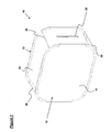
- FIG 1 shows a first embodiment of a background unit according to the invention, which is generally designated 10 and forms part of first and second embodiments of the apparatus according to the invention.
- the background unit 10 comprises a pair of identical panels 12, a connecting web 20, and four support struts 30 (only three of which are visible in Figure 1 ).
- the panels 12 and the connecting web 20 together define an enclosure of the background unit 10.
- Each panel 12 comprises a sheet of flexible material that is mounted within a resilient frame.
- the sheet of flexible material of one of the panels 12 is formed of a knitted fabric having a white colouration, with an elastomeric coating of white colouration on its external surface, and defines an illuminating wall 18.
- the illuminating wall 18 is adapted to transmit light from the interior of the background unit 10 to its exterior.
- the sheet of flexible material of the other panel 12 is substantially opaque.
- the connecting web 20 is formed of knitted fabric that is of white colouration, and has an elastomeric coating of black colouration on its external surface.
- the connecting web 20 extends between the frames of the panels 12.
- the connecting web 20 includes an opening having the form of a slit in the connecting web 20.
- the opening in the connecting web 20 is variable in size by means of a zip closure 22 that is closable from either end of the opening by means of a pair of zips.
- the background unit 10 also includes four removable support struts 30 (only three of which are visible in Figure 1 ) that each extend between opposed parts of the frames of the panels 12, and are situated externally of the connecting web 20.
- Each support strut 30 has a notch at each end, with each notch receiving part of an inner edge of the resilient hoop 16 and the associated parts of the fabric tube 14.
- the support struts 30 are spaced approximately equidistantly around the external surface of the connecting web 20, and act to slightly stretch the fabric of the connecting web 20.
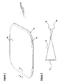
- the background unit 10 With the support struts 30 engaged, as shown in Figure 1 , the background unit 10 has the form of a box that retains its shape during use. When the background unit 10 is no longer needed, it can be collapsed by removing the support struts 30. In particular, the support struts 30 are removed by increasing the separation of the panels 12 slightly, and hence causing additional stretching of the fabric of the connecting web 20, and then removing the resilient hoops 16 from the notches of the support struts 30. Once the support struts 30 have been disengaged from the panels 12, the background unit 10 may be collapsed into the configuration shown in Figure 2 . In this configuration, the panels 12 lie alongside one another, with the connecting web 20 folded between the panels 12.
- the background unit 10 may then be collapsed further by grasping opposite sides of the folded panels 12 and twisting the folded panels 12 to form loops which can then be folded over.
- the background unit 10 when in its erected configuration, is adapted to be used with a light source 40 so as to provide an illuminated background for an object being photographed.
- light directed through the opening in the connecting web 20 into the interior of the background unit 10 is reflected in all directions by the interior surface of the background unit 10, and transmitted through the illuminating wall 18.
- the illuminating wall 18 therefore becomes illuminated, and hence either provides an illuminated background for an object to be photographed or acts to illuminate a separate translucent sheet to form an illuminated background.
- the illuminated background may be situated behind, above, below or to the side of the object, and particular embodiments of the apparatus according to the invention are discussed in more detail below.
- the subject 50 of the photograph to be taken which is in the illustrated case a person, is positioned directly in front of the illuminating wall 18 of the background unit 10.
- the camera 60 is arranged so that the exterior surface of the illuminating wall 18 forms the background of the photograph to be taken.
- the intensity of the light emitted by the light source 40 needs to be sufficient for the illuminating wall 18 to be illuminated to such an extent, relative to the exposure settings of the camera 60, that the illuminating wall 18 is over-exposed in the photograph. Additional light sources (not shown in the Figures) may also be used to illuminate the subject 50 directly.
- the apparatus comprises the background unit 10 described above, a rigid platform 80, a light source 40, a photographic camera 60 and a housing 70.
- the background unit 10 rests upon the substantially opaque panel 12 so that both panels 12 are orientated horizontally, and the opening 22 is situated on one side of the background unit 10.
- the light source 40 is arranged so that light is directed through the opening 22 into the interior of the background unit 10.
- the light source 40 is arranged so that light is directed principally towards the interior surfaces of the connecting web 20 and the opaque panel 12.
- the rigid platform 80 is formed of a sheet of transparent plastics material, and is shaped and dimensioned so as to be received with an interference fit within the resilient hoop 16 and associated fabric tube 14 of the upper panel 12, and rests upon the upper surface of the fabric of that panel 12.
- the housing 70 rests upon the rigid platform 80.
- the housing 70 comprises four panels 72 that are similar in structure to the panels 12 of the background unit 10, but with a front panel 72 having only a frame and hence defining an opening into the housing 70. These four panels 72 are connected at their vertical edges by flexible webs so as to form a generally cuboidal arrangement.
- the housing 70 has an open base, but a sheet of flexible translucent material extends between the upper edges of the panels 72 so as to form an upper wall for the housing 70.
- a pair of crocodile clips 76 are provided within the housing 70 at the rear of the upper wall, as shown in Figure 6 .
- a flexible sheet of translucent plastics material 74 is suspended from the crocodile clips 76, and extends along a curved path to the lower edge of the front panel 72, such that when viewed through the open front panel 72 of the housing 70 the translucent sheet 74 is generally concave in form.
- the subject 52 of the photograph to be taken which in the illustrated case is a telephone, is positioned on the upper surface of the translucent sheet 74 at the base of the housing 72, as shown in Figure 5 .
- the camera 60 is then arranged so that the translucent sheet 74 forms the background of the photograph to be taken.
- the intensity of the light emitted by the light source 40 needs to be sufficient for the translucent sheet 74 to be illuminated by the illuminating wall 18 of the upper panel 12 to such an extent, relative to the exposure settings of the camera 60, that the translucent sheet 74 is over-exposed in the photograph.
- Additional light sources may also be used to direct light through the walls of the housing 70 to illuminate the subject 52 itself.
- the housing 70 When the apparatus is no longer required, the housing 70 may be collapsed and then stowed in a pouch or other receptacle until it is next required.
- the panels 72 are folded so as to lie on top of one another, and opposite sides of the folded panels 72 are then grasped and twisted to form loops which can then be folded over.
- the background unit 10 may be collapsed by removing the support struts 30, as described in more detail above.
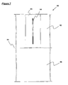
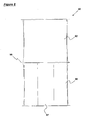
- Figures 7 and 8 show a second embodiment of a background unit according to the invention, which is generally designated 90 and forms part of a third embodiment of the apparatus according to the invention.
- the third embodiment of the apparatus according to the invention is similar to the second embodiment shown in Figures 5 and 6 , but comprises the background unit 90 that is shown in Figures 7 and 8 in place of the background unit 10 and the housing 70 of the second embodiment.
- the background unit 90 comprises a housing 92 and an illuminating enclosure 96.
- the housing 92 and the illuminating enclosure 96 each comprise upper and lower panels, a connecting web, and support struts, and hence are both of similar construction to the background unit 10 shown in Figure 1 .
- the housing 92 and the illuminating enclosure 96 are arranged such that a single central panel 95 constitutes both the lower panel of the housing 92 and the upper panel of the illuminating enclosure 96.
- the resilient hoop of each panel is of greater thickness than the resilient hoops of the background unit 10 of Figure 1 .
- a rigid platform (not visible in Figures 7 and 8 ), which is identical to the rigid platform 80 of the apparatus of Figures 5 and 6 , is received with an interference fit within the resilient hoop and associated fabric tube of the central panel 95, and rests upon the upper surface of the fabric of that panel 95.
- the housing 92 includes an opening in a front surface of its connecting web, and a removable closure 93 for that opening. Co-operating strips of hook-and-loop fasteners are provided on a part of the connecting web that is adjacent to the opening, and also the peripheral portions of the closure 93, so that the closure 93 may be releasably secured across the opening.
- the closure 93 is formed with an opening that has the form of a slit in the fabric of the closure 93 and is orientated vertically along a centre line of the closure 93.
- the opening in the closure 93 is variable in size by means of a zip closure 93 that is closable from either end of the opening by means of a pair of zips.
- the housing 92 also includes a translucent sheet that is arranged in an identical manner to the translucent sheet 74 of the housing 70 of the second embodiment.
- a flexible sheet of translucent plastics material is suspended within the housing 92 by means of crocodile clips situated at the rear of the upper wall of the housing 92.
- the translucent sheet extends along a curved path to a lower front edge of the housing 92, such that when viewed through the opening in the housing 92, or the opening in the closure 93, the translucent sheet is generally concave in form.
- the illuminating enclosure 96 includes an opening 97 in a rear surface of its connecting web.
- the third embodiment of the apparatus according to the invention is similar to the second embodiment shown in Figures 5 and 6 , but comprises the background unit 90 shown in Figures 7 and 8 in place of the illuminating enclosure 10 and the housing 70 shown in Figures 5 and 6 .
- the light source is therefore arranged so that light is directed through the opening 97 into the interior of the illuminating enclosure 96.
- the subject of the photograph to be taken is positioned on the upper surface of the translucent sheet at the base of the housing 92.
- the camera may then be arranged so that the closure 93 is disengaged from the housing 92 and the subject is visible to the camera through the opening in the connecting web of the housing 92.
- the closure 93 may be engaged with the housing 92 so that the subject is only visible to the camera through the opening in the closure 93. This will generally involve the lens portion of the camera projecting through the opening in the closure 93.
- the zip closure 94 would then be adjusted so that the opening is closed as much as possible whilst still enabling a photograph to be taken.
- the camera is arranged so that the translucent sheet forms the background of the photograph to be taken.
- the intensity of the light emitted by the light source needs to be sufficient for the translucent sheet to be illuminated by the illuminating wall of the central panel 95 to such an extent, relative to the exposure settings of the camera, that the translucent sheet is over-exposed in the photograph.
- Additional light sources (not shown in the Figures) will also need to be used to direct light through the walls of the housing 92 to illuminate the subject itself.
- the background unit 90 When the background unit 90 is no longer needed, it can be collapsed by removing the support struts.
- the support struts are removed by increasing the separation of the panels slightly, and hence causing additional stretching of the fabric of the connecting webs, and then removing the resilient hoops from the notches of the support struts.
- the background unit 90 may be collapsed into a configuration in which the panels and the rigid platform lie alongside one another, with the connecting webs folded between the panels.
Landscapes
- Physics & Mathematics (AREA)
- General Physics & Mathematics (AREA)
- Engineering & Computer Science (AREA)
- General Engineering & Computer Science (AREA)
- Studio Devices (AREA)
- Accessories Of Cameras (AREA)
- Photographic Developing Apparatuses (AREA)
- Cameras Adapted For Combination With Other Photographic Or Optical Apparatuses (AREA)
- Image Input (AREA)
Applications Claiming Priority (2)
| Application Number | Priority Date | Filing Date | Title |
|---|---|---|---|
| GB0618614A GB2442018B (en) | 2006-09-22 | 2006-09-22 | Photographic apparatus |
| PCT/GB2007/050564 WO2008035118A1 (en) | 2006-09-22 | 2007-09-20 | Photographic apparatus |
Publications (2)
| Publication Number | Publication Date |
|---|---|
| EP2064591A1 EP2064591A1 (en) | 2009-06-03 |
| EP2064591B1 true EP2064591B1 (en) | 2011-10-19 |
Family
ID=37421385
Family Applications (1)
| Application Number | Title | Priority Date | Filing Date |
|---|---|---|---|
| EP07804467A Active EP2064591B1 (en) | 2006-09-22 | 2007-09-20 | Photographic apparatus |
Country Status (9)
| Country | Link |
|---|---|
| US (1) | US8059948B2 (es) |
| EP (1) | EP2064591B1 (es) |
| JP (1) | JP5355405B2 (es) |
| AT (1) | ATE529777T1 (es) |
| DK (1) | DK2064591T3 (es) |
| ES (1) | ES2375415T3 (es) |
| GB (1) | GB2442018B (es) |
| RU (1) | RU2009115205A (es) |
| WO (1) | WO2008035118A1 (es) |
Families Citing this family (13)
| Publication number | Priority date | Publication date | Assignee | Title |
|---|---|---|---|---|
| GB0816947D0 (en) * | 2008-09-16 | 2008-10-22 | Lastolite Ltd | Photographic lighting apparatus |
| US20100296801A1 (en) * | 2009-04-23 | 2010-11-25 | Laurie Lane | Portable studio |
| US8145048B2 (en) * | 2009-10-02 | 2012-03-27 | Messier Sylvain | Photo booth and improvements thereto |
| US9200770B2 (en) * | 2010-06-18 | 2015-12-01 | Alice M. Chun | Solar light assembly |
| US11248755B2 (en) | 2010-06-18 | 2022-02-15 | Luminaid Lab, Llc | Inflatable solar-powered light |
| US8678601B2 (en) * | 2011-11-18 | 2014-03-25 | Robert Lee Morris | Collapsible light modifier for portable flash |
| EP2844910B1 (en) | 2012-05-01 | 2018-04-04 | LuminAID LAB, LLC | Inflatable solar-powered light |
| GB2505485B (en) * | 2012-08-31 | 2014-11-26 | Manfrotto Uk Ltd | Improvements relating to photographic lighting apparatus |
| GB201320340D0 (en) | 2013-11-18 | 2014-01-01 | Manfrotto Lighting Ltd | Photographic background assembly |
| USD932078S1 (en) | 2015-07-14 | 2021-09-28 | Luminaid Lab, Llc | Expandable light |
| US10760746B2 (en) | 2016-11-04 | 2020-09-01 | Luminaid Lab, Llc | Solar lamp with radial elements and electronics assembly contained in a watertight enclosure |
| WO2018085783A1 (en) | 2016-11-04 | 2018-05-11 | Luminaid Lab, Llc | Multi-powering solar lamps |
| US12038151B2 (en) | 2021-07-12 | 2024-07-16 | Alice Chun | Collapsible and expandable portable lamp and solar-charging battery assembly |
Family Cites Families (9)
| Publication number | Priority date | Publication date | Assignee | Title |
|---|---|---|---|---|
| US4052607A (en) * | 1976-08-26 | 1977-10-04 | Raymond George Larson | Versatile light diffuser |
| JPS60104929A (ja) * | 1983-11-11 | 1985-06-10 | Yutaka Terashita | 撮影照明用リフレクタ |
| US4757425A (en) * | 1985-11-25 | 1988-07-12 | The F. J. Westcott Co. | Photographic light diffuser |
| US5154503A (en) | 1991-03-11 | 1992-10-13 | F. J. Westcott Company | Photographic light modifier |
| GB9724557D0 (en) * | 1997-11-21 | 1998-01-21 | Graham Martin C | Collapsible light diffusing device and diffused lighting apparatus |
| DE69913603T2 (de) * | 1998-05-25 | 2004-09-16 | Horowitz, Ross M. | Modulares System zum Plazieren und Beleuchten von Objekten in der Photographie |
| JP2000035607A (ja) * | 1998-07-17 | 2000-02-02 | Casio Comput Co Ltd | 撮影補助装置 |
| US6947666B2 (en) * | 2003-10-22 | 2005-09-20 | Hewlett-Packard Development Company, L.P. | Support apparatus and method for use with a camera and strobe lights |
| US7418197B2 (en) * | 2004-12-01 | 2008-08-26 | Alpha Photography Inc. | Back light screen for chroma-key photography |
-
2006
- 2006-09-22 GB GB0618614A patent/GB2442018B/en not_active Expired - Fee Related
-
2007
- 2007-09-20 EP EP07804467A patent/EP2064591B1/en active Active
- 2007-09-20 US US12/441,739 patent/US8059948B2/en active Active
- 2007-09-20 RU RU2009115205/28A patent/RU2009115205A/ru not_active Application Discontinuation
- 2007-09-20 ES ES07804467T patent/ES2375415T3/es active Active
- 2007-09-20 DK DK07804467.4T patent/DK2064591T3/da active
- 2007-09-20 AT AT07804467T patent/ATE529777T1/de not_active IP Right Cessation
- 2007-09-20 JP JP2009528796A patent/JP5355405B2/ja active Active
- 2007-09-20 WO PCT/GB2007/050564 patent/WO2008035118A1/en not_active Ceased
Also Published As
| Publication number | Publication date |
|---|---|
| DK2064591T3 (da) | 2012-01-09 |
| EP2064591A1 (en) | 2009-06-03 |
| JP5355405B2 (ja) | 2013-11-27 |
| WO2008035118A1 (en) | 2008-03-27 |
| GB2442018B (en) | 2010-06-30 |
| JP2010504548A (ja) | 2010-02-12 |
| US8059948B2 (en) | 2011-11-15 |
| ATE529777T1 (de) | 2011-11-15 |
| GB0618614D0 (en) | 2006-11-01 |
| GB2442018A (en) | 2008-03-26 |
| US20090269045A1 (en) | 2009-10-29 |
| RU2009115205A (ru) | 2010-10-27 |
| ES2375415T3 (es) | 2012-02-29 |
Similar Documents
| Publication | Publication Date | Title |
|---|---|---|
| EP2064591B1 (en) | Photographic apparatus | |
| US5311409A (en) | Collapsible photographic light diffuser | |
| US7055976B2 (en) | Collapsible tabletop lighting apparatus | |
| US4428030A (en) | Modular light-diffusing or reflecting plastic panel | |
| US7978971B1 (en) | Collapsible softbox for photography lighting | |
| US8145048B2 (en) | Photo booth and improvements thereto | |
| US4979325A (en) | Display frame for photographs and other sheet like documents | |
| WO2004072724A2 (en) | Photography shooting tent | |
| US6106125A (en) | Foldable modular light diffusion box | |
| JP3226107U (ja) | 可搬式撮影台 | |
| US20070086088A1 (en) | Projection screens | |
| JP3673850B2 (ja) | 撮影用システムボックス | |
| US20110170276A1 (en) | Photographic lighting apparatus | |
| WO2020009641A1 (en) | Foldable frame for holding an image | |
| GB2077948A (en) | Back projection screen | |
| US20050166435A1 (en) | Display apparatus | |
| US2885927A (en) | Viewing apparatus | |
| CN220539382U (zh) | 摄影棚 | |
| EP4310590A1 (en) | A concave projection screen | |
| CN205427412U (zh) | 一种便携的静物摄影箱 | |
| GB2238957A (en) | Portable flip-chart stand/case/presenter | |
| JPH07236106A (ja) | 背面投写形画像表示装置 | |
| JP3074934U (ja) | 簡易撮影台 | |
| JP3686613B2 (ja) | 写真撮影用の機器及び該機器に使用するカーテン | |
| JP3139289U (ja) | 撮影照明用機材 |
Legal Events
| Date | Code | Title | Description |
|---|---|---|---|
| PUAI | Public reference made under article 153(3) epc to a published international application that has entered the european phase |
Free format text: ORIGINAL CODE: 0009012 |
|
| 17P | Request for examination filed |
Effective date: 20090324 |
|
| AK | Designated contracting states |
Kind code of ref document: A1 Designated state(s): AT BE BG CH CY CZ DE DK EE ES FI FR GB GR HU IE IS IT LI LT LU LV MC MT NL PL PT RO SE SI SK TR |
|
| AX | Request for extension of the european patent |
Extension state: AL BA HR MK RS |
|
| 17Q | First examination report despatched |
Effective date: 20101209 |
|
| GRAP | Despatch of communication of intention to grant a patent |
Free format text: ORIGINAL CODE: EPIDOSNIGR1 |
|
| DAX | Request for extension of the european patent (deleted) | ||
| GRAS | Grant fee paid |
Free format text: ORIGINAL CODE: EPIDOSNIGR3 |
|
| GRAA | (expected) grant |
Free format text: ORIGINAL CODE: 0009210 |
|
| AK | Designated contracting states |
Kind code of ref document: B1 Designated state(s): AT BE BG CH CY CZ DE DK EE ES FI FR GB GR HU IE IS IT LI LT LU LV MC MT NL PL PT RO SE SI SK TR |
|
| REG | Reference to a national code |
Ref country code: GB Ref legal event code: FG4D |
|
| REG | Reference to a national code |
Ref country code: CH Ref legal event code: EP |
|
| REG | Reference to a national code |
Ref country code: IE Ref legal event code: FG4D |
|
| REG | Reference to a national code |
Ref country code: CH Ref legal event code: NV Representative=s name: DR. LUSUARDI AG |
|
| REG | Reference to a national code |
Ref country code: DE Ref legal event code: R096 Ref document number: 602007018101 Country of ref document: DE Effective date: 20111215 |
|
| REG | Reference to a national code |
Ref country code: SE Ref legal event code: TRGR |
|
| REG | Reference to a national code |
Ref country code: DK Ref legal event code: T3 |
|
| REG | Reference to a national code |
Ref country code: NL Ref legal event code: T3 |
|
| REG | Reference to a national code |
Ref country code: ES Ref legal event code: FG2A Ref document number: 2375415 Country of ref document: ES Kind code of ref document: T3 Effective date: 20120229 |
|
| LTIE | Lt: invalidation of european patent or patent extension |
Effective date: 20111019 |
|
| REG | Reference to a national code |
Ref country code: AT Ref legal event code: MK05 Ref document number: 529777 Country of ref document: AT Kind code of ref document: T Effective date: 20111019 |
|
| PG25 | Lapsed in a contracting state [announced via postgrant information from national office to epo] |
Ref country code: IS Free format text: LAPSE BECAUSE OF FAILURE TO SUBMIT A TRANSLATION OF THE DESCRIPTION OR TO PAY THE FEE WITHIN THE PRESCRIBED TIME-LIMIT Effective date: 20120219 Ref country code: BE Free format text: LAPSE BECAUSE OF FAILURE TO SUBMIT A TRANSLATION OF THE DESCRIPTION OR TO PAY THE FEE WITHIN THE PRESCRIBED TIME-LIMIT Effective date: 20111019 Ref country code: LT Free format text: LAPSE BECAUSE OF FAILURE TO SUBMIT A TRANSLATION OF THE DESCRIPTION OR TO PAY THE FEE WITHIN THE PRESCRIBED TIME-LIMIT Effective date: 20111019 |
|
| PG25 | Lapsed in a contracting state [announced via postgrant information from national office to epo] |
Ref country code: LV Free format text: LAPSE BECAUSE OF FAILURE TO SUBMIT A TRANSLATION OF THE DESCRIPTION OR TO PAY THE FEE WITHIN THE PRESCRIBED TIME-LIMIT Effective date: 20111019 Ref country code: GR Free format text: LAPSE BECAUSE OF FAILURE TO SUBMIT A TRANSLATION OF THE DESCRIPTION OR TO PAY THE FEE WITHIN THE PRESCRIBED TIME-LIMIT Effective date: 20120120 Ref country code: SI Free format text: LAPSE BECAUSE OF FAILURE TO SUBMIT A TRANSLATION OF THE DESCRIPTION OR TO PAY THE FEE WITHIN THE PRESCRIBED TIME-LIMIT Effective date: 20111019 Ref country code: PT Free format text: LAPSE BECAUSE OF FAILURE TO SUBMIT A TRANSLATION OF THE DESCRIPTION OR TO PAY THE FEE WITHIN THE PRESCRIBED TIME-LIMIT Effective date: 20120220 |
|
| REG | Reference to a national code |
Ref country code: CH Ref legal event code: PFA Owner name: MANFROTTO LIGHTING LIMITED Free format text: LASTOLITE LIMITED#UNIT 18 ATLAS ROAD#HERMITAGE INDUSTRIAL ESTATE COALVILLE LEICESTERSHIRE LE67 3FQ (GB) -TRANSFER TO- MANFROTTO LIGHTING LIMITED#UNIT 18 ATLAS ROAD#HERMITAGE INDUSTRIAL ESTATE COALVILLE (GB) |
|
| REG | Reference to a national code |
Ref country code: NL Ref legal event code: TD Effective date: 20120612 |
|
| PG25 | Lapsed in a contracting state [announced via postgrant information from national office to epo] |
Ref country code: CY Free format text: LAPSE BECAUSE OF FAILURE TO SUBMIT A TRANSLATION OF THE DESCRIPTION OR TO PAY THE FEE WITHIN THE PRESCRIBED TIME-LIMIT Effective date: 20111019 |
|
| REG | Reference to a national code |
Ref country code: DE Ref legal event code: R082 Ref document number: 602007018101 Country of ref document: DE Representative=s name: GULDE HENGELHAUPT ZIEBIG & SCHNEIDER, DE |
|
| PG25 | Lapsed in a contracting state [announced via postgrant information from national office to epo] |
Ref country code: SK Free format text: LAPSE BECAUSE OF FAILURE TO SUBMIT A TRANSLATION OF THE DESCRIPTION OR TO PAY THE FEE WITHIN THE PRESCRIBED TIME-LIMIT Effective date: 20111019 Ref country code: CZ Free format text: LAPSE BECAUSE OF FAILURE TO SUBMIT A TRANSLATION OF THE DESCRIPTION OR TO PAY THE FEE WITHIN THE PRESCRIBED TIME-LIMIT Effective date: 20111019 Ref country code: EE Free format text: LAPSE BECAUSE OF FAILURE TO SUBMIT A TRANSLATION OF THE DESCRIPTION OR TO PAY THE FEE WITHIN THE PRESCRIBED TIME-LIMIT Effective date: 20111019 Ref country code: BG Free format text: LAPSE BECAUSE OF FAILURE TO SUBMIT A TRANSLATION OF THE DESCRIPTION OR TO PAY THE FEE WITHIN THE PRESCRIBED TIME-LIMIT Effective date: 20120119 |
|
| RAP2 | Party data changed (patent owner data changed or rights of a patent transferred) |
Owner name: MANFROTTO LIGHTING LIMITED |
|
| PLBE | No opposition filed within time limit |
Free format text: ORIGINAL CODE: 0009261 |
|
| STAA | Information on the status of an ep patent application or granted ep patent |
Free format text: STATUS: NO OPPOSITION FILED WITHIN TIME LIMIT |
|
| PG25 | Lapsed in a contracting state [announced via postgrant information from national office to epo] |
Ref country code: IT Free format text: LAPSE BECAUSE OF FAILURE TO SUBMIT A TRANSLATION OF THE DESCRIPTION OR TO PAY THE FEE WITHIN THE PRESCRIBED TIME-LIMIT Effective date: 20111019 Ref country code: PL Free format text: LAPSE BECAUSE OF FAILURE TO SUBMIT A TRANSLATION OF THE DESCRIPTION OR TO PAY THE FEE WITHIN THE PRESCRIBED TIME-LIMIT Effective date: 20111019 Ref country code: RO Free format text: LAPSE BECAUSE OF FAILURE TO SUBMIT A TRANSLATION OF THE DESCRIPTION OR TO PAY THE FEE WITHIN THE PRESCRIBED TIME-LIMIT Effective date: 20111019 |
|
| REG | Reference to a national code |
Ref country code: DE Ref legal event code: R082 Ref document number: 602007018101 Country of ref document: DE Representative=s name: GULDE HENGELHAUPT ZIEBIG & SCHNEIDER, DE Effective date: 20120724 Ref country code: DE Ref legal event code: R081 Ref document number: 602007018101 Country of ref document: DE Owner name: MANFROTTO LIGHTING LTD., GB Free format text: FORMER OWNER: LASTOLITE LTD., COALVILLE, GB Effective date: 20120724 Ref country code: DE Ref legal event code: R081 Ref document number: 602007018101 Country of ref document: DE Owner name: MANFROTTO UK LTD., GB Free format text: FORMER OWNER: LASTOLITE LTD., COALVILLE, GB Effective date: 20120724 Ref country code: DE Ref legal event code: R082 Ref document number: 602007018101 Country of ref document: DE Representative=s name: GULDE & PARTNER PATENT- UND RECHTSANWALTSKANZL, DE Effective date: 20120724 Ref country code: DE Ref legal event code: R081 Ref document number: 602007018101 Country of ref document: DE Owner name: MANFROTTO UK LTD., GB Free format text: FORMER OWNER: LASTOLITE LTD., COALVILLE, LEICESTERSHIRE, GB Effective date: 20120724 |
|
| 26N | No opposition filed |
Effective date: 20120720 |
|
| REG | Reference to a national code |
Ref country code: DE Ref legal event code: R097 Ref document number: 602007018101 Country of ref document: DE Effective date: 20120720 |
|
| PG25 | Lapsed in a contracting state [announced via postgrant information from national office to epo] |
Ref country code: AT Free format text: LAPSE BECAUSE OF FAILURE TO SUBMIT A TRANSLATION OF THE DESCRIPTION OR TO PAY THE FEE WITHIN THE PRESCRIBED TIME-LIMIT Effective date: 20111019 |
|
| PG25 | Lapsed in a contracting state [announced via postgrant information from national office to epo] |
Ref country code: MC Free format text: LAPSE BECAUSE OF NON-PAYMENT OF DUE FEES Effective date: 20120930 |
|
| REG | Reference to a national code |
Ref country code: IE Ref legal event code: MM4A |
|
| PG25 | Lapsed in a contracting state [announced via postgrant information from national office to epo] |
Ref country code: IE Free format text: LAPSE BECAUSE OF NON-PAYMENT OF DUE FEES Effective date: 20120920 |
|
| PGFP | Annual fee paid to national office [announced via postgrant information from national office to epo] |
Ref country code: FI Payment date: 20130917 Year of fee payment: 7 Ref country code: CH Payment date: 20130916 Year of fee payment: 7 Ref country code: DK Payment date: 20130923 Year of fee payment: 7 Ref country code: ES Payment date: 20130919 Year of fee payment: 7 Ref country code: SE Payment date: 20130917 Year of fee payment: 7 Ref country code: NL Payment date: 20130919 Year of fee payment: 7 |
|
| PG25 | Lapsed in a contracting state [announced via postgrant information from national office to epo] |
Ref country code: MT Free format text: LAPSE BECAUSE OF FAILURE TO SUBMIT A TRANSLATION OF THE DESCRIPTION OR TO PAY THE FEE WITHIN THE PRESCRIBED TIME-LIMIT Effective date: 20111019 |
|
| REG | Reference to a national code |
Ref country code: DE Ref legal event code: R082 Ref document number: 602007018101 Country of ref document: DE Representative=s name: GULDE HENGELHAUPT ZIEBIG & SCHNEIDER, DE |
|
| REG | Reference to a national code |
Ref country code: CH Ref legal event code: PFA Owner name: MANFROTTO UK LIMITED, GB Free format text: FORMER OWNER: MANFROTTO LIGHTING LIMITED, GB |
|
| REG | Reference to a national code |
Ref country code: NL Ref legal event code: TD Effective date: 20140305 |
|
| REG | Reference to a national code |
Ref country code: DE Ref legal event code: R082 Ref document number: 602007018101 Country of ref document: DE Representative=s name: GULDE HENGELHAUPT ZIEBIG & SCHNEIDER, DE Effective date: 20140131 Ref country code: DE Ref legal event code: R081 Ref document number: 602007018101 Country of ref document: DE Owner name: MANFROTTO UK LTD., GB Free format text: FORMER OWNER: MANFROTTO LIGHTING LTD., COALVILLE, GB Effective date: 20140131 Ref country code: DE Ref legal event code: R082 Ref document number: 602007018101 Country of ref document: DE Representative=s name: GULDE & PARTNER PATENT- UND RECHTSANWALTSKANZL, DE Effective date: 20140131 Ref country code: DE Ref legal event code: R081 Ref document number: 602007018101 Country of ref document: DE Owner name: MANFROTTO UK LTD., GB Free format text: FORMER OWNER: MANFROTTO LIGHTING LTD., COALVILLE, LEICESTERSHIRE, GB Effective date: 20140131 |
|
| REG | Reference to a national code |
Ref country code: FR Ref legal event code: CA Effective date: 20140218 Ref country code: FR Ref legal event code: CD Owner name: MANFROTTO UK LIMITED, GB Effective date: 20140218 |
|
| REG | Reference to a national code |
Ref country code: ES Ref legal event code: PC2A Owner name: MANFROTTO UK LIMITED Effective date: 20140424 |
|
| PG25 | Lapsed in a contracting state [announced via postgrant information from national office to epo] |
Ref country code: TR Free format text: LAPSE BECAUSE OF FAILURE TO SUBMIT A TRANSLATION OF THE DESCRIPTION OR TO PAY THE FEE WITHIN THE PRESCRIBED TIME-LIMIT Effective date: 20111019 |
|
| PG25 | Lapsed in a contracting state [announced via postgrant information from national office to epo] |
Ref country code: LU Free format text: LAPSE BECAUSE OF NON-PAYMENT OF DUE FEES Effective date: 20120920 |
|
| PG25 | Lapsed in a contracting state [announced via postgrant information from national office to epo] |
Ref country code: HU Free format text: LAPSE BECAUSE OF FAILURE TO SUBMIT A TRANSLATION OF THE DESCRIPTION OR TO PAY THE FEE WITHIN THE PRESCRIBED TIME-LIMIT Effective date: 20070920 |
|
| REG | Reference to a national code |
Ref country code: DK Ref legal event code: EBP Effective date: 20140930 |
|
| PG25 | Lapsed in a contracting state [announced via postgrant information from national office to epo] |
Ref country code: FI Free format text: LAPSE BECAUSE OF NON-PAYMENT OF DUE FEES Effective date: 20140920 |
|
| REG | Reference to a national code |
Ref country code: CH Ref legal event code: PL |
|
| REG | Reference to a national code |
Ref country code: SE Ref legal event code: EUG |
|
| PG25 | Lapsed in a contracting state [announced via postgrant information from national office to epo] |
Ref country code: SE Free format text: LAPSE BECAUSE OF NON-PAYMENT OF DUE FEES Effective date: 20140921 |
|
| PG25 | Lapsed in a contracting state [announced via postgrant information from national office to epo] |
Ref country code: NL Free format text: LAPSE BECAUSE OF NON-PAYMENT OF DUE FEES Effective date: 20150401 |
|
| PG25 | Lapsed in a contracting state [announced via postgrant information from national office to epo] |
Ref country code: LI Free format text: LAPSE BECAUSE OF NON-PAYMENT OF DUE FEES Effective date: 20140930 Ref country code: CH Free format text: LAPSE BECAUSE OF NON-PAYMENT OF DUE FEES Effective date: 20140930 |
|
| PG25 | Lapsed in a contracting state [announced via postgrant information from national office to epo] |
Ref country code: DK Free format text: LAPSE BECAUSE OF NON-PAYMENT OF DUE FEES Effective date: 20140930 |
|
| REG | Reference to a national code |
Ref country code: ES Ref legal event code: FD2A Effective date: 20160203 |
|
| PG25 | Lapsed in a contracting state [announced via postgrant information from national office to epo] |
Ref country code: ES Free format text: LAPSE BECAUSE OF NON-PAYMENT OF DUE FEES Effective date: 20140921 |
|
| REG | Reference to a national code |
Ref country code: FR Ref legal event code: PLFP Year of fee payment: 10 |
|
| REG | Reference to a national code |
Ref country code: FR Ref legal event code: PLFP Year of fee payment: 11 |
|
| REG | Reference to a national code |
Ref country code: FR Ref legal event code: PLFP Year of fee payment: 12 |
|
| REG | Reference to a national code |
Ref country code: DE Ref legal event code: R081 Ref document number: 602007018101 Country of ref document: DE Owner name: VIDENDUM MEDIA SOLUTIONS UK LIMITED, GB Free format text: FORMER OWNER: MANFROTTO UK LTD., RICHMOND, GB Ref country code: DE Ref legal event code: R082 Ref document number: 602007018101 Country of ref document: DE Representative=s name: GULDE & PARTNER PATENT- UND RECHTSANWALTSKANZL, DE Ref country code: DE Ref legal event code: R081 Ref document number: 602007018101 Country of ref document: DE Owner name: VITEC IMAGING SOLUTIONS UK LIMITED, GB Free format text: FORMER OWNER: MANFROTTO UK LTD., RICHMOND, GB |
|
| REG | Reference to a national code |
Ref country code: FR Ref legal event code: PLFP Year of fee payment: 16 |
|
| REG | Reference to a national code |
Ref country code: DE Ref legal event code: R081 Ref document number: 602007018101 Country of ref document: DE Owner name: VIDENDUM MEDIA SOLUTIONS UK LIMITED, GB Free format text: FORMER OWNER: VITEC IMAGING SOLUTIONS UK LIMITED, RICHMOND, GB |
|
| PGFP | Annual fee paid to national office [announced via postgrant information from national office to epo] |
Ref country code: DE Payment date: 20250919 Year of fee payment: 19 |
|
| PGFP | Annual fee paid to national office [announced via postgrant information from national office to epo] |
Ref country code: GB Payment date: 20250918 Year of fee payment: 19 |
|
| PGFP | Annual fee paid to national office [announced via postgrant information from national office to epo] |
Ref country code: FR Payment date: 20250919 Year of fee payment: 19 |