EP2064514B2 - Surface sensing device - Google Patents
Surface sensing device Download PDFInfo
- Publication number
- EP2064514B2 EP2064514B2 EP07804102.7A EP07804102A EP2064514B2 EP 2064514 B2 EP2064514 B2 EP 2064514B2 EP 07804102 A EP07804102 A EP 07804102A EP 2064514 B2 EP2064514 B2 EP 2064514B2
- Authority
- EP
- European Patent Office
- Prior art keywords
- rotation
- sensing device
- axis
- support
- probe
- Prior art date
- Legal status (The legal status is an assumption and is not a legal conclusion. Google has not performed a legal analysis and makes no representation as to the accuracy of the status listed.)
- Active
Links
Images


Classifications
-
- G—PHYSICS
- G01—MEASURING; TESTING
- G01B—MEASURING LENGTH, THICKNESS OR SIMILAR LINEAR DIMENSIONS; MEASURING ANGLES; MEASURING AREAS; MEASURING IRREGULARITIES OF SURFACES OR CONTOURS
- G01B5/00—Measuring arrangements characterised by the use of mechanical techniques
- G01B5/004—Measuring arrangements characterised by the use of mechanical techniques for measuring coordinates of points
- G01B5/008—Measuring arrangements characterised by the use of mechanical techniques for measuring coordinates of points using coordinate measuring machines
- G01B5/012—Contact-making feeler heads therefor
-
- G—PHYSICS
- G01—MEASURING; TESTING
- G01B—MEASURING LENGTH, THICKNESS OR SIMILAR LINEAR DIMENSIONS; MEASURING ANGLES; MEASURING AREAS; MEASURING IRREGULARITIES OF SURFACES OR CONTOURS
- G01B7/00—Measuring arrangements characterised by the use of electric or magnetic techniques
- G01B7/004—Measuring arrangements characterised by the use of electric or magnetic techniques for measuring coordinates of points
- G01B7/008—Measuring arrangements characterised by the use of electric or magnetic techniques for measuring coordinates of points using coordinate measuring machines
- G01B7/012—Contact-making feeler heads therefor
Definitions
- the present invention relates to a surface-sensing device for use in position determining apparatus such as, for example, a co-ordinate-measuring machine (CMM), a scanning machine, a machine tool or an inspection/ measurement robot.
- CCM co-ordinate-measuring machine
- Such a position determining machine (see for example US-A- 3,727,119 which describes a CMM) is used for measuring a workpiece, and typically comprises an arm moveable in three directions x,y,z relative to a table on which the workpiece is supported. Movement of the arm in each of the directions x,y,z is measured by transducers on the machine, and a probe provided on the arm produces a signal indicating the relationship between the workpiece surface to be measured, and the arm. The position of the surface may thus be determined.
- the table moves in x and y and the arm moves in z.
- Such a scanning probe apparatus comprises a probe head, which is rotatable about two mutually perpendicular axes relative to a fixed structure, and a probe assembly including a stylus.
- the head is mounted on the arm of the machine with one of its axes aligned with the axis of the arm.
- Transducers associated with each of the rotatable axes of the head determine the orientation of the axis of the probe assembly relative to the axis of the arm of the machine.
- the stylus is mounted through a rotatable support to the probe head.
- a third motor is provided for rotating this rotatable support and thus the stylus about a third axis, which is parallel to the stylus axis.
- WO-A-2004 003 466 describes a coordinate measuring machine carrying a probe head, which is rotatable about two mutually perpendicular axes, said probe head further carrying a stylus.
- the coordinate measuring machine further includes a holder for holding the stylus portion of the probe head stationary such that, when held stationary by the holder, the stylus can be re-orientated with respect to the probe head using the motors of the coordinate measuring machine.
- the Renishaw PH9 is a two-axis motorised probe head, which orients a probe by means of two serially connected rotors. Each of the rotors may occupy one of a plurality of kinematic rest locations equispaced about its axis of rotation.
- EP 0392660 relates to a manually operable version of this probe head for use on machines which do not have computer control.
- the machine and/or the probe head cause the stylus tip to move over the surface of the workpiece, in accordance with instructions from a machine controller, to gather data about the workpiece surface. From the signals provided by the measuring transducers of the machine and probe head, and from the knowledge of the dimensions of the surface sensing device, a prediction can be made about the position of the stylus tip (and therefore of the position of the surface).
- a typical workpiece may be for example a car engine block, which has numerous holes at a variety of angles. It is desirable to obtain information from the entire surface of the workpiece; therefore the stylus must be able to reach all of the surfaces.
- probes for example those with ball styli such as touch trigger probes, are multi-directional; this means that they are able to sense a workpiece in a number of directions. Some probes however are uni-directional, such as optical probes and surface finish probes; this means they are only able to sense a workpiece in one direction, limiting the number of surfaces they can reach.
- the stylus tip Due to the varying shapes of the workpiece, and the physical dimensions and limitations of the probe head movement, the stylus tip is sometimes unable to reach the surface of the workpiece. Thus, information about the profile of the surface cannot be obtained.
- a first aspect of the present invention provides apparatus for measuring a surface of a workpiece comprising:
- a holder is provided for holding the surface sensing device stationary during said rotation of the support relative to the surface sensing device.
- a pin is provided on one of the holder and the surface sensing device which is engageable with at least one recess on the other of the holder and the surface sensing device, for holding the surface sensing device stationary during the rotation of the support relative to the surface sensing device.
- first and second axes of rotation of the support are orthogonal.
- the third rotational axis of the surface-sensing device intersects the second axis of the support.
- the third rotational axis of the surface-sensing device is the generally longitudinal axis of the surface sensing device.
- the third axis may alternatively be, for example, at an angle to the longitudinal axis of the surface sensing device.
- Rotation about the third axis of the probe or stylus may allow a uni-directional probe to act as a multidirectional probe, increasing the number of surfaces that can be accessed by uni-directional probes.
- the surface sensing device senses a surface in a direction transverse to or offset from the third axis of rotation. In other embodiments the surface sensing device may sense, for example in the direction of the third axis of the surface sensing device.
- the surface sensing device may be a contact probe, or a non-contact probe.
- Non-contact probes include for example optical probes, capacitive probes and inductive probes.
- the surface-sensing device comprises a probe body, a stylus, and a stylus tip.
- the surface-sensing device comprises a surface finish probe.
- the surface sensing device may comprise for example a laser spot probe or a laser line probe.
- the rotation means allows the surface sensing device to rotate through up to and including, 360 degrees.
- the rotation means may allow the surface sensing device to rotate through greater than 360 degrees.
- it may allow it to rotate continuously, without end stops, for example by making use of slip rings to provide electrical contact between the probe and the probe head.
- the rotation means is additionally manually actuatable.
- a second aspect of the present invention provides a method for using an apparatus for measuring a surface of a workpiece, the apparatus comprising a support, an attachment means for attaching the support to the moveable arm of a machine, a surface sensing device for sensing the surface of a workpiece, the support having a first member rotatable relative to the attachment means about a first axis of rotation, actuated by a first motor; and a second member rotatable relative to the first member about a second axis of rotation, actuated by a second motor; wherein the second axis of rotation is transverse to the first axis of rotation and wherein the surface sensing device is attachable to the second member for rotation therewith, a rotation means for allowing rotation of the surface sensing device with respect to the support about a third axis of rotation, wherein the third axis of rotation is alignable with the first axis of rotation, characterised in that the method comprises the following steps:
- the method further comprises the steps of:
- measuring the surface of the workpiece comprises scanning the surface of the workpiece.
- a co-ordinate system in a coordinate-positioning machine can be defined by three mutually orthogonal axes, 1A, 2A and 3A, whereby in use 1A is substantially vertical and 3A is substantially horizontal. If axis 1A is taken to lie at 0 degrees in the plane of the paper, movement from said 0 degrees position to a 90 degrees position, also in the plane of the paper, can be brought about by rotation in an anticlockwise direction about an axis 2A.
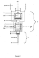
- FIG. 1 shows a preferred embodiment of the invention in three dimensions
- Fig 2 shows a section through the device in a plane defined by axes 1A and 2A in Fig 1
- a support 7 in this case an articulating probe head, comprises first and second housing members 1 and 2 respectively.
- the first housing member 1 is adapted for attachment to a position determining apparatus 26 (for example the arm of a CMM), and houses a motor M1 for effecting angular displacement of a first shaft 20 about a first axis 1A.
- Attached to the first shaft 20 is the second housing member 2, which houses a motor M2 for effecting angular displacement of a second shaft 22 about a second axis 2A.
- Attached to the second shaft 22 for rotation therewith is a surface-sensing device 4 such as a surface-sensing probe.
- the surface sensing probe 4 extends along an axis 4A, transverse to and intersecting axis 2A.
- Said probe comprises a probe body 9, a stylus 8, and a stylus tip 5.
- the probe is provided with a rotation means 6, which allows the device to rotate generally about a third axis, in this case, its longitudinal axis. In this embodiment the rotation means allows the device to rotate through up to 360 degrees.
- the rotation means is actuated by the drive in the support (motor M1 in this embodiment), using a slipping ring and an external fixture.
- the device may rotate through up to 360 degrees, as wires between the two moving parts prevent further rotation.
- the rotation means is provided on the probe body of the surface-sensing device, enabling the device to rotate about its longitudinal axis.
- the rotation means may be provided by an additional member located between the support and the surface-sensing device. In the latter case the surface-sensing device rotates about the longitudinal axis of the additional member, which should be substantially aligned with the axis of the surface-sensing device; therefore the device rotates generally about its longitudinal axis.
- the surface-sensing device may be for example a contact probe, or a non-contact probe.
- Non-contact probes include, for example, optical, capacitance and inductance probes.
- the invention is useful for single axis probes such as optical probes and surface finish probes. This is because for these types of probes especially, rotation about the longitudinal axis (axis 4A) greatly increases the number of surfaces the probe can access. Rotation about this axis is also particularly useful for laser line probes as it is possible to rotate the line about the axis of the surface sensing device (the third axis as mentioned above).
- Fig 3 shows a section through a preferred embodiment of the surface-sensing probe.
- the probe includes means for rotation about its longitudinal axis.
- the probe body 9 comprises a probe mount 30, a main body part 32, and a slipping ring 34.
- the main body part is held at one end 38 by the probe mount 30, and its other end 40 supports a detachable stylus 8.
- the main body part has a recess 36 around its circumference into which the slipping ring 34 fits.
- the main body part 32 and the probe mount 30 are attached so that they are rotatably moveable with respect to each other; this movement has a low slipping torque due to the materials of the parts.
- the slipping ring 34 lies closer to the end 40 of the main body part 32 that supports the detachable stylus 8.
- the slipping torque between the slipping ring 34 and the main body part 32 is higher than the slipping torque between the main body part 32 and the probe mount 30.
- This higher slipping torque may be achieved by sprung plungers pushing against the ring 34 or the main body part 32 of the probe, to increase the friction between the two parts.
- the slipping ring 34 is harder to turn than the probe mount 30, with respect to the main body part 32 of the probe.
- the probe mount 30 is provided with a circumferential groove 31 for mounting it onto, for example, a stylus change port as shown in figure 5 .
- Figure 4 shows a front on view of a preferred embodiment of the surface-sensing probe.
- the slipping ring 34 is provided with a series of recesses in the form of notches 50 located around the circumference.
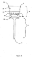
- Figure 5 shows an underside view of a stylus change-port 70 adapted to include a sprung pin 72, and a front view of the surface sensing probe mounted on an articulating probe head 7.
- the longitudinal axis 4A of the surface-sensing probe 4 is aligned with the rotational axis 1A of the first housing member 1 of the support 7.
- the surface-sensing probe 4 can be rotated about its longitudinal axis 4A, powered by the drive means M1 of the support 7.
- the device is moved into the stylus change port 70, which is fitted with a sprung pin 72 orientated such that the pin may engage with any one of the notches 50 provided on the first slipping ring 34.
- the change port 70 is provided with a lip 71 which fits into the groove 31 provided on the probe mount 30, allowing the probe to be stored in the change port 70 when not in use.
- one notch 50a on the slipping ring 34 engages with the sprung pin 72 on the stylus change port.
- the pin 72 holds the slipping ring 34 stationary; this in turn holds the main body part of the probe 32, and in turn the stylus 8, stationary due to the high slipping torque between the slipping ring 34 and main body part 32.
- Other ways of holding the probe body and stylus still relative to the support are possible, such as a socket receptor, magnetic holder, mechanical clamp, or electromechanical clamp, or a friction holder.
- the lower slipping torque between the main body part 32 and the probe mount 30 allows the probe mount to continue to rotate with the rotation of the support 7.
- the probe mount 30 and the support 7 rotate relative to the main body part 32 until the probe mount 30 and support 7 reach a reference position with respect to the main body part 32.
- the probe mount and the main body part stop relative to each other by means of a 'sliding peg' mechanism, as illustrated in figure 6 .
- Figure 6 shows a plan and side cross-sectional view through the probe body 9.
- a curved slot 25 is provided at a known position in the probe mount 30.
- a first stop block 5 is secured to the probe mount 30 through the slot 25 by two spacers 35. Said first stop block 5, along with the spacers 35, is moveable in two directions along the slot 25.
- a second stop block 15 is provided on the main body part 32 of the probe.
- the first stop block 5 is moved towards the second stop block 15, for example in a clockwise direction.
- the probe mount continues to rotate, stopping when a spacer 35 contacts the edge 45 of the slot 25.
- the position of the probe mount 30 and support 7 reach a reference position with respect to the main body part 32.
- the first stop block 5 may also be moved towards the second stop block 15 in an anti-clockwise direction. After the two stop blocks have made contact the probe mount 30 continues to rotate until a spacer 35 contacts the other edge of the slot 55.
- the first and second stop blocks and slot are sized such that this mechanism ensures that the reference position is always at exactly the same point, independent of the side from which the stop block on the probe mount 30 is approached.
- the position of the main body part of the probe 32, and consequently the stylus 8 and stylus tip 5, is then defined relative to the support 7 in a reference position.
- Other ways to define a reference position of the probe body relative to the support are possible. These include for example, any kind of reference marks such as and optical reference mark for use with a camera, a magnetic reference mark (as described in our US patent no. US 6,051,971 ), alignable reference marks. Alternatively a detent mechanism may be used.
- the support 7 is then able to rotate itself and the probe mount 30 to position the support and probe mount at the exact angle required, relative to the stylus 8 and the stylus tip 5.
- the movement of the support relative to the probe body 32 and stylus 8 from the reference position can be measured using positioning means, such as encoders, which may already be provided in the support 7. Alternatively it may be measured indirectly for example using a scale and a vernier, one provided on the stationary probe body 32 or slipping ring 34, and the other on the moving probe mount 30 or support 7. In this case a viewing camera, either in the port or separate to the port, may be used to assess the distance travelled by the support relative to the probe body and stylus, or the distance may be assessed by eye.
- positioning means such as encoders, which may already be provided in the support 7.
- it may be measured indirectly for example using a scale and a vernier, one provided on the stationary probe body 32 or slipping ring 34, and the other on the moving probe mount 30 or support 7.
- a viewing camera either in the port or separate to the port, may be used to assess the distance travelled by the support relative to the probe body and stylus, or the distance may be assessed by eye.
- the movement of the support relative to the probe body 32 and stylus 8 from the reference position may alternatively be measured using positioning means, such as an encoder, in the probe head itself.
- positioning means such as an encoder
- the positioning means in the probe head will feed information on the relative positions of the probe body and the support, back to the motors in the support.
- the probe body may have an indexer, which can rotated a defined number of index points to a known position.
- the support and probe mount 30 When the support and probe mount 30 are positioned at the exact angle required relative to the stylus 8 and the stylus tip 5, the support 7 is driven away from the stylus change port 70 and the sprung pin 72, disengaging the slipping ring 34. In this way the stylus tip 5 can be orientated in different angles about the longitudinal axis of the probe with respect to the support 7, enabling the surface-sensing probe 4 to reach a greater variety of surfaces.
- the orientation of the stylus tip 5 with respect to the support 7 may also be carried out using for example a motor in the probe body 9, and a slipping ring. In this case the orientation of the stylus tip 5 is adjusted independently of the support 7.
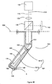
- Figure 7 shows a schematic diagram of the means for detecting the sensing relationship of the surface-sensing device with the surface of the workpiece, in this case using a surface finish probe.
- a laser 100 in the main body part 32 of the probe body 9 directs a beam 200 towards a mirror 150.
- the beam 200 passes through an aperture 110 and a lens 120 into a beam splitter 130.
- the beam 200 passes through the beam splitter 130 and onto the mirror 150, the beam is reflected off the mirror and back to the beam splitter 130, where it is then directed towards a photo sensitive diode (PSD) 140.
- PSD photo sensitive diode
- the mirror 150 is connected to the proximal end of a lever 160, which is balanced on a fulcrum 210.
- the lever 160 is connected to one end of a stylus stem 190 which is connected at its other end to the stylus tip 5.
- a skid 180 rests along either side of the tip.
- the stylus tip 5 is preferably a diamond tip, as it needs to be hard wearing to not break as it is dragged along a surface.
- Figure 12 shows a schematic diagram of an alternative means for detecting the sensing relationship of the surface-sensing device with the surface of the workpiece.
- the stylus 8' (as shown in Figure 4 ), housed by housing 185, is detachable from the probe head along line 500.
- the lever 161 is fixed with respect to the housing of the stylus 185 by two crossed flat springs 155. When the stylus tip 5 contacts the surface of a workpiece the stylus tip 5 will be pushed back into the housing of the stylus. This movement causes the lever 161 to rotate about the pivot point where the cross springs meet, in turn the mirror 150 is caused to move.
- a screw 175 can be tightened to apply pressure to another spring 165 which urges the stylus tip 5 towards the workpiece.
- the stylus tip 5 typically protrudes up to 100 microns from the edge of the skid 180.
- a screw 195 is provided adjacent to the lever 161 to adjust the amount that the stylus tip 5 protrudes from the edge of the skid 180.
- Figure 13 shows a plan cross-sectional view of the alternative means for detecting the sensing relationship of the surface-sensing device with the surface of the workpiece as shown in figure 12 .
- the lever 161 has 2 sections, a first section 161C which is provided proximal to the mirror 150, and a second section 161D which is provided proximal to the stylus tip 5.
- the second section 161D is triangular in shape so as to minimise sideways movement of the lever and thus the stylus tip 5 (which protrudes from the stylus through a hole 162 in the skid 180).
- the skid 180 follows the rough contour (surface waviness) of the surface whilst diamond tip 5 follows the detailed surface texture of the surface.
- the position of the lever 160 varies, as does the position of the mirror 150.
- the laser beam directed towards it is reflected at a different angle, and as a consequence the laser spot on the PSD is moved, as shown in figure 7 . In this way the profile of the surface of the workpiece can be measured.
- the skid is fixed relative to the probe stylus, and the probe stylus is stiff. As the surface-sensing device is dragged along a surface, the stiff stylus and fixed skid allow the surface-sensing device to be pushed towards the surface with a substantially constant torque.
- the stylus may be deflectable and the skid moveable; in this case the deflection of the stylus can be transduced to determine the skid's contact with the workpiece surface.
- Figures 8 to 11 show four embodiments of the orientation of the stylus tip 5 and stylus face 300 of the surface-sensing device.
- the stylus tip 5 is perpendicular to the skid 180, and to the face of the stylus 300.
- the face of the stylus 300 and thus the stylus tip 5 may be provided at an angle to the longitudinal rotational axis of the probe 4A, as shown in figure 8 , to aid the stylus tip 5 when moving into large holes.
- the face 300 of the stylus may alternatively be provided at 90 degrees to the longitudinal rotational axis of the probe 4A in order to inspect under a workpiece; in this case the stylus tip 5 lies parallel to the longitudinal rotational axis of the probe.
- the stylus face 300 may be provided parallel to the longitudinal rotational axis of the probe 4A.
- the stylus tip 5 is perpendicular to the longitudinal rotational axis of the probe, improving accessibility of the inside surface of small bored holes.
- the stylus is cranked at a non-90 degree angle.
- the stylus tip 5 points in a direction transverse to the longitudinal axis of the probe 4A.
- the stylus tip 5 When sensing the surface of a workpiece the stylus tip 5 must point in a direction perpendicular to the surface 301. Due to certain restrictions on the movement of the articulating probe head, and the size of the articulating probe head, it is not possible to achieve the described perpendicular sensing arrangement with a straight stylus as shown in figure 10 .
- the cranked stylus of figure 11 allows the stylus tip to be positioned so that the probe head clears the surface, and thus allows the stylus tip 5 to access a greater number of surfaces from a perpendicular position.
- Figure 14 shows a schematic diagram of means for detecting the sensing relationship of the surface-sensing device with the surface of the workpiece in a cranked stylus.
- the stylus 501 housed by housing 185, is detachable from the probe head along line 500.
- the lever arrangement is provided in the cranked portion of the stylus whilst the light path arrangement is provided in the straight part of the stylus.
- the mirror is provided at the interface between the two parts at an angle so as to return the optical beam to the beam splitter in a similar way to that of the straight stylus. This means that the cranked stylus can use the same optics and thus the same probe mount as used by the straight stylus.
- stylus face 300 and stylus tip 5 may be provided at any angle, with respect to the longitudinal rotational axis of the probe, for convenience of workpiece surface access.
- the probe tip is aligned with the longitudinal axis of the surface-sensing device, the probe has no advantage with respect to access when rotated about the longitudinal axis of the surface sensing device. Consequently, to benefit from the advantage of increased accessibility of workpiece surfaces by rotating the surface-sensing device about its longitudinal axis, the probe tip must be transverse to or offset from said longitudinal axis.
Priority Applications (1)
| Application Number | Priority Date | Filing Date | Title |
|---|---|---|---|
| EP10000459.7A EP2207006B2 (en) | 2006-09-05 | 2007-08-31 | Surface sensing device |
Applications Claiming Priority (3)
| Application Number | Priority Date | Filing Date | Title |
|---|---|---|---|
| GB0617344A GB0617344D0 (en) | 2006-09-05 | 2006-09-05 | Surface sensing device |
| GB0708572A GB0708572D0 (en) | 2007-05-03 | 2007-05-03 | Surface sensing device |
| PCT/GB2007/003295 WO2008029094A1 (en) | 2006-09-05 | 2007-08-31 | Surface sensing device |
Related Child Applications (3)
| Application Number | Title | Priority Date | Filing Date |
|---|---|---|---|
| EP10000459.7A Division EP2207006B2 (en) | 2006-09-05 | 2007-08-31 | Surface sensing device |
| EP10000459.7A Division-Into EP2207006B2 (en) | 2006-09-05 | 2007-08-31 | Surface sensing device |
| EP10000459.7 Division-Into | 2010-01-19 |
Publications (3)
| Publication Number | Publication Date |
|---|---|
| EP2064514A1 EP2064514A1 (en) | 2009-06-03 |
| EP2064514B1 EP2064514B1 (en) | 2010-03-03 |
| EP2064514B2 true EP2064514B2 (en) | 2014-08-06 |
Family
ID=39156862
Family Applications (2)
| Application Number | Title | Priority Date | Filing Date |
|---|---|---|---|
| EP10000459.7A Active EP2207006B2 (en) | 2006-09-05 | 2007-08-31 | Surface sensing device |
| EP07804102.7A Active EP2064514B2 (en) | 2006-09-05 | 2007-08-31 | Surface sensing device |
Family Applications Before (1)
| Application Number | Title | Priority Date | Filing Date |
|---|---|---|---|
| EP10000459.7A Active EP2207006B2 (en) | 2006-09-05 | 2007-08-31 | Surface sensing device |
Country Status (7)
| Country | Link |
|---|---|
| US (1) | US8006399B2 (ja) |
| EP (2) | EP2207006B2 (ja) |
| JP (1) | JP5124579B2 (ja) |
| CN (1) | CN102564306B (ja) |
| AT (1) | ATE459856T1 (ja) |
| DE (1) | DE602007005150D1 (ja) |
| WO (1) | WO2008029094A1 (ja) |
Families Citing this family (23)
| Publication number | Priority date | Publication date | Assignee | Title |
|---|---|---|---|---|
| GB0501690D0 (en) * | 2005-01-27 | 2005-03-02 | Renishaw Plc | Articulating device |
| SE533198C2 (sv) * | 2008-02-14 | 2010-07-20 | Hexagon Metrology Ab | Mätanordning med mäthuvud för kontrollmätning av föremål |
| GB0804114D0 (en) * | 2008-03-05 | 2008-04-09 | Renishaw Plc | Surface sensing device |
| EP2381212B1 (en) * | 2010-04-26 | 2018-04-25 | Tesa Sa | Coordinate measuring system for rotationally symmetric workpieces |
| EP2384851B1 (en) * | 2010-05-03 | 2018-01-03 | Tesa Sa | Coordinate Measuring System with rotatory adapter |
| EP2614333B1 (de) * | 2010-09-10 | 2021-08-11 | Carl Zeiss 3D Automation GmbH | Taststift-anordnung |
| JP6104557B2 (ja) * | 2012-10-18 | 2017-03-29 | 株式会社ミツトヨ | 表面粗さ測定ユニット、三次元測定装置 |
| US8881611B2 (en) * | 2013-02-26 | 2014-11-11 | The Boeing Company | Automated inspection system |
| DE102015203369B4 (de) | 2015-02-25 | 2020-02-20 | Carl Zeiss Industrielle Messtechnik Gmbh | Verfahren zum Bestimmen der Messbedingungen eines Rauheitssensors, Verfahren zum Vermessen der Rauheit einer Werkstückoberfläche, Computerprogrammprodukt sowie Messgerät eingerichtet zur Durchführung der Verfahren |
| DE102015209193A1 (de) | 2015-05-20 | 2016-11-24 | Carl Zeiss Industrielle Messtechnik Gmbh | Verfahren zur Erfassung dynamischer Schwingungen eines Rauheitssensors, Verfahren zur Vermessung der Rauheit einer Werkstückoberfläche, Computerprogrammprodukt sowie Messgerät eingerichtet zur Durchführung der Verfahren. |
| JP6649013B2 (ja) * | 2015-08-27 | 2020-02-19 | 株式会社ミツトヨ | プローブヘッド回転機構 |
| WO2017161193A1 (en) * | 2016-03-16 | 2017-09-21 | Hexagon Metrology, Inc. | Optical probe with crash protection and probe clips |
| US10663274B2 (en) | 2017-01-27 | 2020-05-26 | Faro Technologies, Inc | Articulated arm coordinate measuring machine |
| GB201702391D0 (en) | 2017-02-14 | 2017-03-29 | Renishaw Plc | Surface sensing device |
| WO2018150178A1 (en) | 2017-02-15 | 2018-08-23 | Renishaw Plc | Surface finish or surface roughness probe |
| DE102017103938A1 (de) | 2017-02-24 | 2018-08-30 | Carl Zeiss Industrielle Messtechnik Gmbh | Vorrichtung zum Messen der Rauheit einer Werkstückoberfläche |
| DE102017105814B3 (de) | 2017-03-17 | 2018-05-30 | Carl Zeiss Industrielle Messtechnik Gmbh | System zum Messen der Rauheit einer Oberfläche eines Werkstücks |
| DE102017106425B4 (de) | 2017-03-24 | 2020-02-06 | Carl Zeiss Industrielle Messtechnik Gmbh | Von einem Koordinatenmessgerät verfahrbare Vorrichtung zum Positionieren eines Messinstruments bezüglich eines Werkstücks |
| JP6368986B1 (ja) | 2017-03-27 | 2018-08-08 | 株式会社東京精密 | 検出器、表面性状測定機、及び真円度測定機 |
| DE102017108033A1 (de) | 2017-04-13 | 2018-10-18 | Carl Zeiss Industrielle Messtechnik Gmbh | Verfahren zur Messung von Koordinaten oder Eigenschaften einer Werkstückoberfläche |
| DE102017003641B4 (de) | 2017-04-13 | 2019-10-17 | Carl Zeiss Industrielle Messtechnik Gmbh | Verfahren zur Messung von Koordinaten oder Eigenschaften einer Werkstückoberfläche |
| GB201806830D0 (en) * | 2018-04-26 | 2018-06-13 | Renishaw Plc | Surface finish stylus |
| EP3827219B1 (en) | 2018-07-26 | 2023-08-30 | TESA Sàrl | Accessory for rotary probe support |
Citations (2)
| Publication number | Priority date | Publication date | Assignee | Title |
|---|---|---|---|---|
| DE10100352A1 (de) † | 2001-01-05 | 2002-07-11 | Zeiss Carl | Koordinatenmeßgerät mit einem Spritzschutz für den Tastkopf des Koordinatenmeßgerätes |
| DE10260670A1 (de) † | 2002-12-23 | 2004-07-15 | Carl Zeiss | Vorrichtung zum optischen Abtasten von Werkstücken |
Family Cites Families (31)
| Publication number | Priority date | Publication date | Assignee | Title |
|---|---|---|---|---|
| US2867043A (en) † | 1952-10-16 | 1959-01-06 | Applic Electroniques Des Caout | Variable electric resistance semiconductor devices |
| US3727119A (en) | 1971-02-01 | 1973-04-10 | Information Dev Corp | Servo controlled automatic inspection apparatus |
| US3750295A (en) † | 1971-07-22 | 1973-08-07 | Werkzeugmasch Veb | Measuring machine |
| JPS5775503U (ja) * | 1980-10-27 | 1982-05-10 | ||
| US4882527A (en) * | 1987-10-16 | 1989-11-21 | Nissan Motor Co., Ltd. | Three-dimensional measuring robot |
| DE3740070A1 (de) * | 1987-11-26 | 1989-06-08 | Zeiss Carl Fa | Dreh-schwenk-einrichtung fuer tastkoepfe von koordinatenmessgeraeten |
| GB8803847D0 (en) † | 1988-02-18 | 1988-03-16 | Renishaw Plc | Mounting for surface-sensing device |
| GB8908854D0 (en) † | 1989-04-19 | 1989-06-07 | Renishaw Plc | Method of and apparatus for scanning the surface of a workpiece |
| US5189806A (en) * | 1988-12-19 | 1993-03-02 | Renishaw Plc | Method of and apparatus for scanning the surface of a workpiece |
| DE69003149T2 (de) | 1989-04-14 | 1994-01-05 | Renishaw Plc | Tastkopf. |
| US5124524A (en) † | 1990-11-15 | 1992-06-23 | Laser Design Inc. | Laser alignment and control system |
| DE4039336C5 (de) * | 1990-12-10 | 2004-07-01 | Carl Zeiss | Verfahren zur schnellen Werkstück-Temperaturmessung auf Koordinatenmeßgeräten |
| DE4308823C2 (de) | 1993-03-19 | 2002-11-07 | Zeiss Carl | Messender Tastkopf für Koordinatenmeßgeräte |
| JPH0743102A (ja) * | 1993-07-27 | 1995-02-10 | Etsuzo Fukuda | 測定子の位置ぎめ用具 |
| GB9605278D0 (en) | 1996-03-13 | 1996-05-15 | Renishaw Plc | Opto-electronic scale reading apparatus |
| ES2193087T3 (es) † | 1999-06-26 | 2003-11-01 | Kuka Schweissanlagen Gmbh | Procedimiento y dispositivo para calibrar estaciones de medicion con robots, manipuladores y dispositivos opticos de medicion asociados. |
| DE10006753A1 (de) * | 2000-02-15 | 2001-08-16 | Zeiss Carl | Dreh-Schwenkeinrichtung für den Tastkopf eines Koordinatenmeßgerätes |
| WO2002027270A1 (de) | 2000-09-28 | 2002-04-04 | Carl Zeiss | Koordinatenmessgerät |
| EP1342051B1 (de) * | 2000-09-28 | 2005-10-19 | Carl Zeiss Industrielle Messtechnik GmbH | Kalibrierung eines messenden sensors auf einem koordinatenmessgerät mit einer kugel, deren mittelpunkt bekannt ist |
| JP2003014405A (ja) * | 2001-07-04 | 2003-01-15 | Okuma Corp | ワークの表面・裏面共用計測スタイラス |
| CN100473942C (zh) * | 2002-02-14 | 2009-04-01 | Faro科技有限公司 | 带有一体形成的线激光扫描仪的便携式坐标测量机 |
| FR2837567B1 (fr) † | 2002-03-19 | 2005-05-06 | Romain Granger | Capteur pour machine de mesure de coordonnees tridimensionnelles |
| GB0207912D0 (en) * | 2002-04-05 | 2002-05-15 | Renishaw Plc | Kinematic coupling |
| GB0215152D0 (en) | 2002-07-01 | 2002-08-07 | Renishaw Plc | Probe or stylus orientation |
| CA2522097C (en) † | 2003-04-28 | 2012-09-25 | Stephen James Crampton | Cmm arm with exoskeleton |
| US7257992B2 (en) | 2004-07-06 | 2007-08-21 | Cim Systems, Inc. | Surface finish tester apparatus and methods |
| DE602004010899T2 (de) | 2004-07-16 | 2009-01-02 | Tesa Sa | Lenkbarer Taststift |
| JP4582446B2 (ja) † | 2004-11-18 | 2010-11-17 | 株式会社東京精密 | 測定装置 |
| JP4568621B2 (ja) | 2005-02-28 | 2010-10-27 | 株式会社ミツトヨ | 表面性状測定機の真直度補正方法および表面性状測定機 |
| GB0605796D0 (en) * | 2006-03-23 | 2006-05-03 | Renishaw Plc | Apparatus and method of measuring workpieces |
| EP1978328B1 (en) * | 2007-04-03 | 2015-02-18 | Hexagon Metrology AB | Oscillating scanning probe with constant contact force |
-
2007
- 2007-08-31 EP EP10000459.7A patent/EP2207006B2/en active Active
- 2007-08-31 DE DE602007005150T patent/DE602007005150D1/de active Active
- 2007-08-31 US US12/310,206 patent/US8006399B2/en active Active
- 2007-08-31 WO PCT/GB2007/003295 patent/WO2008029094A1/en active Application Filing
- 2007-08-31 CN CN201110358458.0A patent/CN102564306B/zh active Active
- 2007-08-31 EP EP07804102.7A patent/EP2064514B2/en active Active
- 2007-08-31 JP JP2009527191A patent/JP5124579B2/ja active Active
- 2007-08-31 AT AT07804102T patent/ATE459856T1/de not_active IP Right Cessation
Patent Citations (2)
| Publication number | Priority date | Publication date | Assignee | Title |
|---|---|---|---|---|
| DE10100352A1 (de) † | 2001-01-05 | 2002-07-11 | Zeiss Carl | Koordinatenmeßgerät mit einem Spritzschutz für den Tastkopf des Koordinatenmeßgerätes |
| DE10260670A1 (de) † | 2002-12-23 | 2004-07-15 | Carl Zeiss | Vorrichtung zum optischen Abtasten von Werkstücken |
Also Published As
| Publication number | Publication date |
|---|---|
| EP2207006A2 (en) | 2010-07-14 |
| EP2064514B1 (en) | 2010-03-03 |
| JP2010502976A (ja) | 2010-01-28 |
| US8006399B2 (en) | 2011-08-30 |
| CN102564306B (zh) | 2014-09-24 |
| WO2008029094A1 (en) | 2008-03-13 |
| US20090255139A1 (en) | 2009-10-15 |
| CN102564306A (zh) | 2012-07-11 |
| EP2207006B2 (en) | 2022-01-26 |
| ATE459856T1 (de) | 2010-03-15 |
| DE602007005150D1 (de) | 2010-04-15 |
| EP2207006A3 (en) | 2010-11-03 |
| JP5124579B2 (ja) | 2013-01-23 |
| EP2207006B1 (en) | 2013-10-02 |
| EP2064514A1 (en) | 2009-06-03 |
Similar Documents
| Publication | Publication Date | Title |
|---|---|---|
| EP2064514B2 (en) | Surface sensing device | |
| US7676942B2 (en) | Multi-axis positioning and measuring system and method of using | |
| EP1875158B1 (en) | Surface sensing device with optical sensor | |
| US5822877A (en) | Multi-probe system for dimensional metrology | |
| US8479403B2 (en) | Measuring system | |
| US8468672B2 (en) | Surface sensing device | |
| US8312635B2 (en) | Measuring system | |
| JPH0789045B2 (ja) | 三次元変位量測定器 | |
| US20230236010A1 (en) | Method of calibrating a surface sensing device, corresponding calibrating program for a control computer and corresponding calibration kit | |
| US20180245905A1 (en) | Apparatus for measuring the roughness of a workpiece surface | |
| JP2007054947A (ja) | 紡糸コット研磨機 | |
| CN101512285B (zh) | 表面感测设备 |
Legal Events
| Date | Code | Title | Description |
|---|---|---|---|
| PUAI | Public reference made under article 153(3) epc to a published international application that has entered the european phase |
Free format text: ORIGINAL CODE: 0009012 |
|
| 17P | Request for examination filed |
Effective date: 20090326 |
|
| AK | Designated contracting states |
Kind code of ref document: A1 Designated state(s): AT BE BG CH CY CZ DE DK EE ES FI FR GB GR HU IE IS IT LI LT LU LV MC MT NL PL PT RO SE SI SK TR |
|
| AX | Request for extension of the european patent |
Extension state: AL BA HR MK RS |
|
| GRAP | Despatch of communication of intention to grant a patent |
Free format text: ORIGINAL CODE: EPIDOSNIGR1 |
|
| DAX | Request for extension of the european patent (deleted) | ||
| GRAS | Grant fee paid |
Free format text: ORIGINAL CODE: EPIDOSNIGR3 |
|
| GRAA | (expected) grant |
Free format text: ORIGINAL CODE: 0009210 |
|
| AK | Designated contracting states |
Kind code of ref document: B1 Designated state(s): AT BE BG CH CY CZ DE DK EE ES FI FR GB GR HU IE IS IT LI LT LU LV MC MT NL PL PT RO SE SI SK TR |
|
| REG | Reference to a national code |
Ref country code: GB Ref legal event code: FG4D |
|
| REG | Reference to a national code |
Ref country code: CH Ref legal event code: EP |
|
| REG | Reference to a national code |
Ref country code: IE Ref legal event code: FG4D Ref country code: CH Ref legal event code: NV Representative=s name: KIRKER & CIE S.A. |
|
| REF | Corresponds to: |
Ref document number: 602007005150 Country of ref document: DE Date of ref document: 20100415 Kind code of ref document: P |
|
| REG | Reference to a national code |
Ref country code: NL Ref legal event code: VDEP Effective date: 20100303 |
|
| PG25 | Lapsed in a contracting state [announced via postgrant information from national office to epo] |
Ref country code: LT Free format text: LAPSE BECAUSE OF FAILURE TO SUBMIT A TRANSLATION OF THE DESCRIPTION OR TO PAY THE FEE WITHIN THE PRESCRIBED TIME-LIMIT Effective date: 20100303 |
|
| LTIE | Lt: invalidation of european patent or patent extension |
Effective date: 20100303 |
|
| PG25 | Lapsed in a contracting state [announced via postgrant information from national office to epo] |
Ref country code: PL Free format text: LAPSE BECAUSE OF FAILURE TO SUBMIT A TRANSLATION OF THE DESCRIPTION OR TO PAY THE FEE WITHIN THE PRESCRIBED TIME-LIMIT Effective date: 20100303 Ref country code: LV Free format text: LAPSE BECAUSE OF FAILURE TO SUBMIT A TRANSLATION OF THE DESCRIPTION OR TO PAY THE FEE WITHIN THE PRESCRIBED TIME-LIMIT Effective date: 20100303 Ref country code: FI Free format text: LAPSE BECAUSE OF FAILURE TO SUBMIT A TRANSLATION OF THE DESCRIPTION OR TO PAY THE FEE WITHIN THE PRESCRIBED TIME-LIMIT Effective date: 20100303 Ref country code: AT Free format text: LAPSE BECAUSE OF FAILURE TO SUBMIT A TRANSLATION OF THE DESCRIPTION OR TO PAY THE FEE WITHIN THE PRESCRIBED TIME-LIMIT Effective date: 20100303 Ref country code: SI Free format text: LAPSE BECAUSE OF FAILURE TO SUBMIT A TRANSLATION OF THE DESCRIPTION OR TO PAY THE FEE WITHIN THE PRESCRIBED TIME-LIMIT Effective date: 20100303 |
|
| PG25 | Lapsed in a contracting state [announced via postgrant information from national office to epo] |
Ref country code: NL Free format text: LAPSE BECAUSE OF FAILURE TO SUBMIT A TRANSLATION OF THE DESCRIPTION OR TO PAY THE FEE WITHIN THE PRESCRIBED TIME-LIMIT Effective date: 20100303 Ref country code: GR Free format text: LAPSE BECAUSE OF FAILURE TO SUBMIT A TRANSLATION OF THE DESCRIPTION OR TO PAY THE FEE WITHIN THE PRESCRIBED TIME-LIMIT Effective date: 20100604 Ref country code: CY Free format text: LAPSE BECAUSE OF FAILURE TO SUBMIT A TRANSLATION OF THE DESCRIPTION OR TO PAY THE FEE WITHIN THE PRESCRIBED TIME-LIMIT Effective date: 20100303 Ref country code: BE Free format text: LAPSE BECAUSE OF FAILURE TO SUBMIT A TRANSLATION OF THE DESCRIPTION OR TO PAY THE FEE WITHIN THE PRESCRIBED TIME-LIMIT Effective date: 20100303 Ref country code: SE Free format text: LAPSE BECAUSE OF FAILURE TO SUBMIT A TRANSLATION OF THE DESCRIPTION OR TO PAY THE FEE WITHIN THE PRESCRIBED TIME-LIMIT Effective date: 20100303 Ref country code: RO Free format text: LAPSE BECAUSE OF FAILURE TO SUBMIT A TRANSLATION OF THE DESCRIPTION OR TO PAY THE FEE WITHIN THE PRESCRIBED TIME-LIMIT Effective date: 20100303 Ref country code: EE Free format text: LAPSE BECAUSE OF FAILURE TO SUBMIT A TRANSLATION OF THE DESCRIPTION OR TO PAY THE FEE WITHIN THE PRESCRIBED TIME-LIMIT Effective date: 20100303 Ref country code: ES Free format text: LAPSE BECAUSE OF FAILURE TO SUBMIT A TRANSLATION OF THE DESCRIPTION OR TO PAY THE FEE WITHIN THE PRESCRIBED TIME-LIMIT Effective date: 20100614 |
|
| PLBI | Opposition filed |
Free format text: ORIGINAL CODE: 0009260 |
|
| PG25 | Lapsed in a contracting state [announced via postgrant information from national office to epo] |
Ref country code: CZ Free format text: LAPSE BECAUSE OF FAILURE TO SUBMIT A TRANSLATION OF THE DESCRIPTION OR TO PAY THE FEE WITHIN THE PRESCRIBED TIME-LIMIT Effective date: 20100303 Ref country code: SK Free format text: LAPSE BECAUSE OF FAILURE TO SUBMIT A TRANSLATION OF THE DESCRIPTION OR TO PAY THE FEE WITHIN THE PRESCRIBED TIME-LIMIT Effective date: 20100303 Ref country code: IS Free format text: LAPSE BECAUSE OF FAILURE TO SUBMIT A TRANSLATION OF THE DESCRIPTION OR TO PAY THE FEE WITHIN THE PRESCRIBED TIME-LIMIT Effective date: 20100703 Ref country code: BG Free format text: LAPSE BECAUSE OF FAILURE TO SUBMIT A TRANSLATION OF THE DESCRIPTION OR TO PAY THE FEE WITHIN THE PRESCRIBED TIME-LIMIT Effective date: 20100603 |
|
| 26 | Opposition filed |
Opponent name: CARL ZEISS INDUSTRIELLE MESSTECHNIK GMBH Effective date: 20101118 |
|
| PLAX | Notice of opposition and request to file observation + time limit sent |
Free format text: ORIGINAL CODE: EPIDOSNOBS2 |
|
| PG25 | Lapsed in a contracting state [announced via postgrant information from national office to epo] |
Ref country code: PT Free format text: LAPSE BECAUSE OF FAILURE TO SUBMIT A TRANSLATION OF THE DESCRIPTION OR TO PAY THE FEE WITHIN THE PRESCRIBED TIME-LIMIT Effective date: 20100705 Ref country code: DK Free format text: LAPSE BECAUSE OF FAILURE TO SUBMIT A TRANSLATION OF THE DESCRIPTION OR TO PAY THE FEE WITHIN THE PRESCRIBED TIME-LIMIT Effective date: 20100303 |
|
| PG25 | Lapsed in a contracting state [announced via postgrant information from national office to epo] |
Ref country code: MC Free format text: LAPSE BECAUSE OF NON-PAYMENT OF DUE FEES Effective date: 20100831 |
|
| PLAF | Information modified related to communication of a notice of opposition and request to file observations + time limit |
Free format text: ORIGINAL CODE: EPIDOSCOBS2 |
|
| REG | Reference to a national code |
Ref country code: FR Ref legal event code: ST Effective date: 20110502 |
|
| PLBB | Reply of patent proprietor to notice(s) of opposition received |
Free format text: ORIGINAL CODE: EPIDOSNOBS3 |
|
| PG25 | Lapsed in a contracting state [announced via postgrant information from national office to epo] |
Ref country code: IE Free format text: LAPSE BECAUSE OF NON-PAYMENT OF DUE FEES Effective date: 20100831 Ref country code: FR Free format text: LAPSE BECAUSE OF NON-PAYMENT OF DUE FEES Effective date: 20100831 |
|
| PG25 | Lapsed in a contracting state [announced via postgrant information from national office to epo] |
Ref country code: MT Free format text: LAPSE BECAUSE OF FAILURE TO SUBMIT A TRANSLATION OF THE DESCRIPTION OR TO PAY THE FEE WITHIN THE PRESCRIBED TIME-LIMIT Effective date: 20100303 |
|
| PG25 | Lapsed in a contracting state [announced via postgrant information from national office to epo] |
Ref country code: LU Free format text: LAPSE BECAUSE OF NON-PAYMENT OF DUE FEES Effective date: 20100831 Ref country code: HU Free format text: LAPSE BECAUSE OF FAILURE TO SUBMIT A TRANSLATION OF THE DESCRIPTION OR TO PAY THE FEE WITHIN THE PRESCRIBED TIME-LIMIT Effective date: 20100904 |
|
| PG25 | Lapsed in a contracting state [announced via postgrant information from national office to epo] |
Ref country code: TR Free format text: LAPSE BECAUSE OF FAILURE TO SUBMIT A TRANSLATION OF THE DESCRIPTION OR TO PAY THE FEE WITHIN THE PRESCRIBED TIME-LIMIT Effective date: 20100303 |
|
| RIC2 | Information provided on ipc code assigned after grant |
Ipc: G01B 7/012 20060101ALI20131010BHEP Ipc: G01B 5/012 20060101AFI20131010BHEP |
|
| PUAH | Patent maintained in amended form |
Free format text: ORIGINAL CODE: 0009272 |
|
| STAA | Information on the status of an ep patent application or granted ep patent |
Free format text: STATUS: PATENT MAINTAINED AS AMENDED |
|
| 27A | Patent maintained in amended form |
Effective date: 20140806 |
|
| AK | Designated contracting states |
Kind code of ref document: B2 Designated state(s): AT BE BG CH CY CZ DE DK EE ES FI FR GB GR HU IE IS IT LI LT LU LV MC MT NL PL PT RO SE SI SK TR |
|
| REG | Reference to a national code |
Ref country code: DE Ref legal event code: R102 Ref document number: 602007005150 Country of ref document: DE |
|
| REG | Reference to a national code |
Ref country code: CH Ref legal event code: AELC |
|
| REG | Reference to a national code |
Ref country code: DE Ref legal event code: R102 Ref document number: 602007005150 Country of ref document: DE Effective date: 20140806 |
|
| PG25 | Lapsed in a contracting state [announced via postgrant information from national office to epo] |
Ref country code: LV Free format text: LAPSE BECAUSE OF FAILURE TO SUBMIT A TRANSLATION OF THE DESCRIPTION OR TO PAY THE FEE WITHIN THE PRESCRIBED TIME-LIMIT Effective date: 20140806 |
|
| PGFP | Annual fee paid to national office [announced via postgrant information from national office to epo] |
Ref country code: IT Payment date: 20210820 Year of fee payment: 15 |
|
| PGFP | Annual fee paid to national office [announced via postgrant information from national office to epo] |
Ref country code: GB Payment date: 20210826 Year of fee payment: 15 Ref country code: CH Payment date: 20210823 Year of fee payment: 15 |
|
| PGFP | Annual fee paid to national office [announced via postgrant information from national office to epo] |
Ref country code: DE Payment date: 20211027 Year of fee payment: 15 |
|
| REG | Reference to a national code |
Ref country code: DE Ref legal event code: R119 Ref document number: 602007005150 Country of ref document: DE |
|
| REG | Reference to a national code |
Ref country code: CH Ref legal event code: PL |
|
| GBPC | Gb: european patent ceased through non-payment of renewal fee |
Effective date: 20220831 |
|
| PG25 | Lapsed in a contracting state [announced via postgrant information from national office to epo] |
Ref country code: LI Free format text: LAPSE BECAUSE OF NON-PAYMENT OF DUE FEES Effective date: 20220831 Ref country code: CH Free format text: LAPSE BECAUSE OF NON-PAYMENT OF DUE FEES Effective date: 20220831 |
|
| P01 | Opt-out of the competence of the unified patent court (upc) registered |
Effective date: 20230602 |
|
| PG25 | Lapsed in a contracting state [announced via postgrant information from national office to epo] |
Ref country code: DE Free format text: LAPSE BECAUSE OF NON-PAYMENT OF DUE FEES Effective date: 20230301 |
|
| PG25 | Lapsed in a contracting state [announced via postgrant information from national office to epo] |
Ref country code: GB Free format text: LAPSE BECAUSE OF NON-PAYMENT OF DUE FEES Effective date: 20220831 |