EP2064141B1 - Vorrichtung zur bahnwicklung, im besonderen ein aufwickler - Google Patents
Vorrichtung zur bahnwicklung, im besonderen ein aufwickler Download PDFInfo
- Publication number
- EP2064141B1 EP2064141B1 EP07803713A EP07803713A EP2064141B1 EP 2064141 B1 EP2064141 B1 EP 2064141B1 EP 07803713 A EP07803713 A EP 07803713A EP 07803713 A EP07803713 A EP 07803713A EP 2064141 B1 EP2064141 B1 EP 2064141B1
- Authority
- EP
- European Patent Office
- Prior art keywords
- winding
- section
- windup
- roll
- rider roll
- Prior art date
- Legal status (The legal status is an assumption and is not a legal conclusion. Google has not performed a legal analysis and makes no representation as to the accuracy of the status listed.)
- Not-in-force
Links
- 238000004804 winding Methods 0.000 title claims abstract description 99
- 238000005259 measurement Methods 0.000 claims description 2
- 238000010276 construction Methods 0.000 description 1
- 230000007547 defect Effects 0.000 description 1
- 230000001419 dependent effect Effects 0.000 description 1
Images
Classifications
-
- B—PERFORMING OPERATIONS; TRANSPORTING
- B65—CONVEYING; PACKING; STORING; HANDLING THIN OR FILAMENTARY MATERIAL
- B65H—HANDLING THIN OR FILAMENTARY MATERIAL, e.g. SHEETS, WEBS, CABLES
- B65H18/00—Winding webs
- B65H18/02—Supporting web roll
- B65H18/023—Supporting web roll on its outer circumference
- B65H18/025—Parallel rollers type
-
- B—PERFORMING OPERATIONS; TRANSPORTING
- B65—CONVEYING; PACKING; STORING; HANDLING THIN OR FILAMENTARY MATERIAL
- B65H—HANDLING THIN OR FILAMENTARY MATERIAL, e.g. SHEETS, WEBS, CABLES
- B65H18/00—Winding webs
- B65H18/08—Web-winding mechanisms
- B65H18/14—Mechanisms in which power is applied to web roll, e.g. to effect continuous advancement of web
- B65H18/145—Reel-to-reel type web winding and unwinding mechanisms
-
- B—PERFORMING OPERATIONS; TRANSPORTING
- B65—CONVEYING; PACKING; STORING; HANDLING THIN OR FILAMENTARY MATERIAL
- B65H—HANDLING THIN OR FILAMENTARY MATERIAL, e.g. SHEETS, WEBS, CABLES
- B65H18/00—Winding webs
- B65H18/08—Web-winding mechanisms
- B65H18/14—Mechanisms in which power is applied to web roll, e.g. to effect continuous advancement of web
- B65H18/20—Mechanisms in which power is applied to web roll, e.g. to effect continuous advancement of web the web roll being supported on two parallel rollers at least one of which is driven
-
- B—PERFORMING OPERATIONS; TRANSPORTING
- B65—CONVEYING; PACKING; STORING; HANDLING THIN OR FILAMENTARY MATERIAL
- B65H—HANDLING THIN OR FILAMENTARY MATERIAL, e.g. SHEETS, WEBS, CABLES
- B65H18/00—Winding webs
- B65H18/08—Web-winding mechanisms
- B65H18/14—Mechanisms in which power is applied to web roll, e.g. to effect continuous advancement of web
- B65H18/22—Mechanisms in which power is applied to web roll, e.g. to effect continuous advancement of web by friction band
-
- B—PERFORMING OPERATIONS; TRANSPORTING
- B65—CONVEYING; PACKING; STORING; HANDLING THIN OR FILAMENTARY MATERIAL
- B65H—HANDLING THIN OR FILAMENTARY MATERIAL, e.g. SHEETS, WEBS, CABLES
- B65H18/00—Winding webs
- B65H18/08—Web-winding mechanisms
- B65H18/26—Mechanisms for controlling contact pressure on winding-web package, e.g. for regulating the quantity of air between web layers
-
- B—PERFORMING OPERATIONS; TRANSPORTING
- B65—CONVEYING; PACKING; STORING; HANDLING THIN OR FILAMENTARY MATERIAL
- B65H—HANDLING THIN OR FILAMENTARY MATERIAL, e.g. SHEETS, WEBS, CABLES
- B65H2301/00—Handling processes for sheets or webs
- B65H2301/40—Type of handling process
- B65H2301/41—Winding, unwinding
- B65H2301/414—Winding
- B65H2301/4148—Winding slitting
- B65H2301/41486—Winding slitting winding on two or more winding shafts simultaneously
Definitions
- the invention relates to a device according to the preamble of claim 1.
- rewinders clinic roller, salvage winder, rewinder
- the rewinder comprises an unwind section, a slitter section and a windup section.
- the web roll is unwound on the unwind section, and the web is passed to the slitter section, in which the web is cut into component webs in the longitudinal direction and possible poor-quality edge parts, i.e. edge trim strips, are cut out of the web.
- the web is guided to the windup section, in which the component webs are wound about cores to form rolls.
- the core of the web roll is attached to core chucks for unwinding and, correspondingly, in the windup section the rolls are held in place by means of core chucks, whose chucks are inserted into the outermost cores.
- the width of rewound rolls varies considerably, typically between 0.5 and 4.3 m, which imposes high demands on core chucks.
- core chucks are fixed to side frames.
- the core chuck structure is typically telescopic, comprising a two-phase operation.
- extension pieces have also often been used in connection with core chuck structures if the roll to be wound has been narrow, for example, having a width of 500 mm.
- extension pieces are laborious because their attachment and detachment takes time. Furthermore, the movable arm of the core chuck or the movable arms in a telescope model, the chuck and the possible extension pieces must be smaller in diameter than the outside diameter of the smallest core in order that the structures shall not touch winding drums at the beginning of winding. Therefore, it has been problematic to achieve sufficient stiffness. The space requirement of the structure has also proved problematic.
- a two-drum type windup section of a rewinder in which component web rolls are wound on support of winding drums by means of a winding nip defined between the growing web roll and one of the drums.
- one winding drum can comprise a set of belt drums in which an endless belt loop is disposed about two drums.
- 'winding drum' is meant, in addition to a conventional winding drum, a winding drum formed of a set of belt drums.
- a rider roll unit to hold the web rolls in place and to provide an additional load.
- the rider roll unit has been typically formed of several rider rolls that are separately loadable, i.e. each rider roll of the rider roll unit has its own loading devices.
- the windup section of the rewinder may also have been a centre-driven winder, in which the web roll being wound up is rotated at the centre, and the winding takes place in a separate winding station by means of a nip defined between the web roll and a winding cylinder.
- Document EP 0 962 411 A1 discloses a rewinder comprising a pair of lower winding rolls defining a winding cradle, which are movable from an upper position toward a lower position during the winding of a reel, in order to keep the axis of the developing reel in an essentially fixed position.
- An object of the invention is to provide a device in which the above-noted drawbacks associated with rewinders are eliminated or at least minimized.
- a particular object of the invention is to create a rewinder that is suitable for use in a wide width range but which is of low cost.
- the device according to the invention is mainly characterized by what is stated in the characterizing part of claim 1.
- the device in accordance with the invention for winding a web, in particular rewinding operates in a wide width range, advantageously with 0.5 - 5.3 m wide rolls, and it is simple in construction and of low cost as well as small in respect of its space requirement.
- the winding station is arranged on a rider roll beam.
- the winding station can also be arranged on another suitable crossbeam already existing in the windup section, for example, on one crossbeam of the ejector, on a gap protection means or on another fixed crossbeam of the windup section.
- the winding carriages of the winding station are arranged to be movable in the transverse and vertical direction such that the winding heads can be placed on core ends.
- Separate actuators are advantageously arranged for the transverse and vertical movements of the winding station, and both force and position measurement is integrated with said actuators in accordance with an advantageous additional feature of the invention.
- small-diameter rolls are used as winding drums and as a rider roll: the winding drums 500-800 mm and the rider roll 100-300 mm, thus allowing the space needed for the structures of the winding station to be readily arranged.
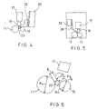
- the diameters of the winding drums and the rider roll are optimized such that the path of movement of the rider roll with respect to the centre of the core produces, when using a core of 76,2 mm (3 inches), a gap which remains on one side and which is larger than 10 mm, preferably 15 mm. This makes it possible for the winding station to be readily brought to its place.
- the invention makes it possible to construct rewinders that are wider than those known in the state of the art.
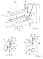
- FIG 1 schematically shows one embodiment of the device in accordance with the invention.
- Figure 2 schematically shows one embodiment of the device in accordance with the invention at the initial stage of winding.
- Figure 3 schematically shows the embodiment shown in Fig. 2 at the final stage of winding.
- Figure 4 is a schematic view of an embodiment in which a winding station is attached to a gap protection means.
- Figure 5 is a schematic view of an embodiment in which a winding station is attached to a fixed crossbeam of a windup section.
- Figure 6 shows a schematic dimensioning example for optimizing the diameters of winding drums and a rider roll.
- the main parts of a rewinder are an unwind section, a slitter section and a windup section 10, in which a web roll wound about a core on a slitter-winder is unwound, slit and rewound.
- the windup section 10 comprises a front drum 12, a rear drum 11, a rider roll 16, and a winding station 20 as well as a rider roll beam 17.
- the winding station 20 comprises two winding carriages 21 and winding heads 23, one for each end of the core. By means of the winding station 20, the core/cores and the web roll/web rolls are held in place in the lateral direction during winding.
- the winding carriage 21 comprises a frame, actuators, and the winding head 23 is attached to it.
Landscapes
- Replacement Of Web Rolls (AREA)
- Winding Of Webs (AREA)
- Electroluminescent Light Sources (AREA)
Claims (9)
- Vorrichtung zum Wickeln einer Bahn, insbesondere ein Umwickler, die eine Abwickelsektion, eine Schneidsektion und eine Aufwickelsektion (10) aufweist, wobei die Aufwickelsektion (10) ein Wickler der Art mit zwei Trommel ist und zwei Wickeltrommeln (11, 12) und eine Wickelstation (20) aufweist, wobei die Aufwickelsektion (10) eine Reiterrolle (16) aufweist, die sich im Wesentlichen über die gesamte Breite der Aufwickelsektion erstreckt,
dadurch gekennzeichnet, dass
die Wickelstation (20) der Aufwickelsektion (10) Wickelschlitten (21) aufweist, die in einer seitlichen Richtung parallel zu der Achse der Reiterrolle (16) und in der vertikalen Richtung mittels eines Aktuators beweglich sind, wobei die Wickelstation (20) des Weiteren Wickelköpfe (23) aufweist. - Vorrichtung gemäß Anspruch 1,
dadurch gekennzeichnet, dass
die Durchmesser (d11, d12, d16) der Wickeltrommeln (11, 12) und der Reiterrolle (16) der Aufwickelsektion (10) derart optimiert sind, dass die Bewegungsbahn der Reiterrolle (16) in Bezug auf die Mitte eines Kerns (23) einen Spalt (z) zwischen einer Wickeltrommel (11) und der Reiterrolle (16) erzeugt, der größer als 10 mm ist. - Vorrichtung gemäß Anspruch 1 oder 2,
dadurch gekennzeichnet, dass
ein Aktuator in Verbindung mit der Reiterrolle (16) angeordnet ist, um diese zu belasten. - Vorrichtung gemäß einem der vorherigen Ansprüche,
dadurch gekennzeichnet, dass
die Aufwickelsektion (10) so eingerichtet ist, dass sie in einem Rollenbreitenbereich von 0,5 - 5,3 m der zu wickelnden Rolle arbeitet. - Vorrichtung gemäß einem der vorherigen Ansprüche,
dadurch gekennzeichnet, dass
eine Kraft- und Positionsmessung mit den Aktuatoren, die die Querbewegung und die vertikale Bewegung des Wickelschlittens (21) der Aufwickelsektion (10) erzeugen, integriert ist. - Vorrichtung gemäß einem der vorherigen Ansprüche,
dadurch gekennzeichnet, dass
die Wickelstation (20) der Aufwickelsektion (10) an einem Reiterrollenbalken (17) angeordnet ist. - Vorrichtung gemäß einem der Ansprüche 1 bis 5,
dadurch gekennzeichnet, dass
die Wickelstation (20) der Aufwickelsektion (10) an einem Querbalken eines Ejektors angeordnet ist. - Vorrichtung gemäß einem der Ansprüche 1 bis 5,
dadurch gekennzeichnet, dass
die Wickelstation (20) der Aufwickelsektion (10) an einer Spaltschutzeinrichtung (27) angebracht ist. - Vorrichtung gemäß einem der Ansprüche 1 bis 5,
dadurch gekennzeichnet, dass
die Wickelstation (20) der Aufwickelsektion (10) an einem fixierten Querbalken der Aufwickelsektion angebracht ist.
Applications Claiming Priority (2)
| Application Number | Priority Date | Filing Date | Title |
|---|---|---|---|
| FI20065533A FI120442B (fi) | 2006-08-28 | 2006-08-28 | Laite rainan rullauksessa, erityisesti uudelleenrullain |
| PCT/FI2007/050450 WO2008025875A1 (en) | 2006-08-28 | 2007-08-20 | Device in winding of a web, in particular a rewinder |
Publications (2)
| Publication Number | Publication Date |
|---|---|
| EP2064141A1 EP2064141A1 (de) | 2009-06-03 |
| EP2064141B1 true EP2064141B1 (de) | 2010-03-03 |
Family
ID=36950713
Family Applications (1)
| Application Number | Title | Priority Date | Filing Date |
|---|---|---|---|
| EP07803713A Not-in-force EP2064141B1 (de) | 2006-08-28 | 2007-08-20 | Vorrichtung zur bahnwicklung, im besonderen ein aufwickler |
Country Status (5)
| Country | Link |
|---|---|
| EP (1) | EP2064141B1 (de) |
| AT (1) | ATE459565T1 (de) |
| DE (1) | DE602007005148D1 (de) |
| FI (1) | FI120442B (de) |
| WO (1) | WO2008025875A1 (de) |
Families Citing this family (2)
| Publication number | Priority date | Publication date | Assignee | Title |
|---|---|---|---|---|
| DE102010064331A1 (de) * | 2010-12-29 | 2012-07-05 | Voith Patent Gmbh | Verfahren zum Aufwickeln einer Papier- oder Kartonbahn und Doppeltragwalzenwickelvorrichtung zum Aufwickeln einer Papier- oder Kartonbahn |
| JP7006938B2 (ja) * | 2018-12-21 | 2022-01-24 | 株式会社ミヤコシ | 連続ラベル用紙の抜き粕巻取り装置 |
Family Cites Families (4)
| Publication number | Priority date | Publication date | Assignee | Title |
|---|---|---|---|---|
| DE9317616U1 (de) * | 1993-11-19 | 1995-03-16 | Beloit Technologies, Inc., Wilmington, Del. | Wickelmaschine |
| FI104065B1 (fi) * | 1998-04-24 | 1999-11-15 | Valmet Corp | Rullauslaite |
| ITFI980131A1 (it) | 1998-06-01 | 1999-12-01 | Celli Spa | Macchina bobinatrice o ribobinatrice per la formazione di rotoli di materiale nastriforme di grande diametro |
| US6715709B2 (en) * | 2002-04-30 | 2004-04-06 | Kimberly-Clark Worldwide, Inc. | Apparatus and method for producing logs of sheet material |
-
2006
- 2006-08-28 FI FI20065533A patent/FI120442B/fi not_active IP Right Cessation
-
2007
- 2007-08-20 AT AT07803713T patent/ATE459565T1/de active
- 2007-08-20 WO PCT/FI2007/050450 patent/WO2008025875A1/en not_active Ceased
- 2007-08-20 DE DE602007005148T patent/DE602007005148D1/de active Active
- 2007-08-20 EP EP07803713A patent/EP2064141B1/de not_active Not-in-force
Also Published As
| Publication number | Publication date |
|---|---|
| WO2008025875A1 (en) | 2008-03-06 |
| ATE459565T1 (de) | 2010-03-15 |
| FI20065533L (fi) | 2008-02-29 |
| EP2064141A1 (de) | 2009-06-03 |
| DE602007005148D1 (de) | 2010-04-15 |
| FI120442B (fi) | 2009-10-30 |
| FI20065533A0 (fi) | 2006-08-28 |
Similar Documents
| Publication | Publication Date | Title |
|---|---|---|
| CN104080719B (zh) | 卷筒退绕机和退绕方法 | |
| CN104105649B (zh) | 幅材材料的卷筒的退绕机 | |
| CN102083722A (zh) | 纤维幅材退绕设备、分切卷绕设备以及退绕纤维幅材的方法 | |
| DE69905410D1 (de) | Wickelmaschine | |
| CA2820162C (en) | Method for separating partial webs in a slitter winder | |
| JP3679226B2 (ja) | 紙ウエブの巻取り方法および巻取り装置 | |
| EP2064141B1 (de) | Vorrichtung zur bahnwicklung, im besonderen ein aufwickler | |
| EP2653422B1 (de) | Verfahren und Vorrichtung zum Wickeln von Faserbahnen, insbesondere von Teilbahnen aus Papier und Pappe | |
| EP2522608B1 (de) | Vorrichtung zum Aufbringen von Klebstoff in eine Rollenschneid- und Wickelmaschine einer Faserbahnmaschine | |
| EP2653421B1 (de) | Verfahren und Vorrichtung zum Wickeln von Faserbahnen, insbesondere von Bahnen aus Papier und Pappe | |
| CN102616598B (zh) | 用于卷绕纤维幅材的装置和方法 | |
| WO2010052374A1 (en) | A method in connection with a slitter winder for a fiber web | |
| CN116767926A (zh) | 收卷装置和收卷方法 | |
| EP2543616B1 (de) | Anordnung in einer Rollenschneid- und Wickelmaschine für eine Faserbahnmaschine | |
| EP2495195B1 (de) | Anordnung bei der Behandlung von Bahnrollen | |
| JP2000318893A (ja) | 巻取装置 | |
| EP2540649B1 (de) | Verfahren und Anordnung in Verbindung mit einem Abwickler | |
| FI123533B (fi) | Laite kuiturainojen, erityisesti paperi- ja kartonkirainojen rullaamiseksi | |
| JP3348441B2 (ja) | 広幅帯状シート用スリッターリワインダー | |
| FI111356B (fi) | Menetelmä ja laite paperirainan kiinnirullauksessa suoritettavassa vaihdossa | |
| CN103189290B (zh) | 用于卷绕纤维幅材的方法和装置 | |
| KR20250162233A (ko) | 슬리터 장치 | |
| FI105466B (fi) | Menetelmä peräkkäisissä rullaimissa ja peräkkäisiä rullaimia käsittävä valmistuslinja |
Legal Events
| Date | Code | Title | Description |
|---|---|---|---|
| PUAI | Public reference made under article 153(3) epc to a published international application that has entered the european phase |
Free format text: ORIGINAL CODE: 0009012 |
|
| 17P | Request for examination filed |
Effective date: 20090210 |
|
| AK | Designated contracting states |
Kind code of ref document: A1 Designated state(s): AT BE BG CH CY CZ DE DK EE ES FI FR GB GR HU IE IS IT LI LT LU LV MC MT NL PL PT RO SE SI SK TR |
|
| AX | Request for extension of the european patent |
Extension state: AL BA HR MK RS |
|
| GRAP | Despatch of communication of intention to grant a patent |
Free format text: ORIGINAL CODE: EPIDOSNIGR1 |
|
| 17Q | First examination report despatched |
Effective date: 20090707 |
|
| RTI1 | Title (correction) |
Free format text: DEVICE FOR WINDING A WEB, IN PARTICULAR A REWINDER |
|
| DAX | Request for extension of the european patent (deleted) | ||
| GRAS | Grant fee paid |
Free format text: ORIGINAL CODE: EPIDOSNIGR3 |
|
| GRAA | (expected) grant |
Free format text: ORIGINAL CODE: 0009210 |
|
| AK | Designated contracting states |
Kind code of ref document: B1 Designated state(s): AT BE BG CH CY CZ DE DK EE ES FI FR GB GR HU IE IS IT LI LT LU LV MC MT NL PL PT RO SE SI SK TR |
|
| REG | Reference to a national code |
Ref country code: GB Ref legal event code: FG4D |
|
| REG | Reference to a national code |
Ref country code: CH Ref legal event code: EP |
|
| REG | Reference to a national code |
Ref country code: IE Ref legal event code: FG4D |
|
| REF | Corresponds to: |
Ref document number: 602007005148 Country of ref document: DE Date of ref document: 20100415 Kind code of ref document: P |
|
| REG | Reference to a national code |
Ref country code: NL Ref legal event code: VDEP Effective date: 20100303 |
|
| PG25 | Lapsed in a contracting state [announced via postgrant information from national office to epo] |
Ref country code: LT Free format text: LAPSE BECAUSE OF FAILURE TO SUBMIT A TRANSLATION OF THE DESCRIPTION OR TO PAY THE FEE WITHIN THE PRESCRIBED TIME-LIMIT Effective date: 20100303 |
|
| LTIE | Lt: invalidation of european patent or patent extension |
Effective date: 20100303 |
|
| PG25 | Lapsed in a contracting state [announced via postgrant information from national office to epo] |
Ref country code: SI Free format text: LAPSE BECAUSE OF FAILURE TO SUBMIT A TRANSLATION OF THE DESCRIPTION OR TO PAY THE FEE WITHIN THE PRESCRIBED TIME-LIMIT Effective date: 20100303 Ref country code: FI Free format text: LAPSE BECAUSE OF FAILURE TO SUBMIT A TRANSLATION OF THE DESCRIPTION OR TO PAY THE FEE WITHIN THE PRESCRIBED TIME-LIMIT Effective date: 20100303 Ref country code: PL Free format text: LAPSE BECAUSE OF FAILURE TO SUBMIT A TRANSLATION OF THE DESCRIPTION OR TO PAY THE FEE WITHIN THE PRESCRIBED TIME-LIMIT Effective date: 20100303 Ref country code: LV Free format text: LAPSE BECAUSE OF FAILURE TO SUBMIT A TRANSLATION OF THE DESCRIPTION OR TO PAY THE FEE WITHIN THE PRESCRIBED TIME-LIMIT Effective date: 20100303 |
|
| PG25 | Lapsed in a contracting state [announced via postgrant information from national office to epo] |
Ref country code: CY Free format text: LAPSE BECAUSE OF FAILURE TO SUBMIT A TRANSLATION OF THE DESCRIPTION OR TO PAY THE FEE WITHIN THE PRESCRIBED TIME-LIMIT Effective date: 20100303 Ref country code: BE Free format text: LAPSE BECAUSE OF FAILURE TO SUBMIT A TRANSLATION OF THE DESCRIPTION OR TO PAY THE FEE WITHIN THE PRESCRIBED TIME-LIMIT Effective date: 20100303 Ref country code: SE Free format text: LAPSE BECAUSE OF FAILURE TO SUBMIT A TRANSLATION OF THE DESCRIPTION OR TO PAY THE FEE WITHIN THE PRESCRIBED TIME-LIMIT Effective date: 20100303 Ref country code: RO Free format text: LAPSE BECAUSE OF FAILURE TO SUBMIT A TRANSLATION OF THE DESCRIPTION OR TO PAY THE FEE WITHIN THE PRESCRIBED TIME-LIMIT Effective date: 20100303 Ref country code: NL Free format text: LAPSE BECAUSE OF FAILURE TO SUBMIT A TRANSLATION OF THE DESCRIPTION OR TO PAY THE FEE WITHIN THE PRESCRIBED TIME-LIMIT Effective date: 20100303 Ref country code: GR Free format text: LAPSE BECAUSE OF FAILURE TO SUBMIT A TRANSLATION OF THE DESCRIPTION OR TO PAY THE FEE WITHIN THE PRESCRIBED TIME-LIMIT Effective date: 20100604 Ref country code: ES Free format text: LAPSE BECAUSE OF FAILURE TO SUBMIT A TRANSLATION OF THE DESCRIPTION OR TO PAY THE FEE WITHIN THE PRESCRIBED TIME-LIMIT Effective date: 20100614 Ref country code: EE Free format text: LAPSE BECAUSE OF FAILURE TO SUBMIT A TRANSLATION OF THE DESCRIPTION OR TO PAY THE FEE WITHIN THE PRESCRIBED TIME-LIMIT Effective date: 20100303 |
|
| PG25 | Lapsed in a contracting state [announced via postgrant information from national office to epo] |
Ref country code: IS Free format text: LAPSE BECAUSE OF FAILURE TO SUBMIT A TRANSLATION OF THE DESCRIPTION OR TO PAY THE FEE WITHIN THE PRESCRIBED TIME-LIMIT Effective date: 20100703 Ref country code: BG Free format text: LAPSE BECAUSE OF FAILURE TO SUBMIT A TRANSLATION OF THE DESCRIPTION OR TO PAY THE FEE WITHIN THE PRESCRIBED TIME-LIMIT Effective date: 20100603 Ref country code: SK Free format text: LAPSE BECAUSE OF FAILURE TO SUBMIT A TRANSLATION OF THE DESCRIPTION OR TO PAY THE FEE WITHIN THE PRESCRIBED TIME-LIMIT Effective date: 20100303 Ref country code: CZ Free format text: LAPSE BECAUSE OF FAILURE TO SUBMIT A TRANSLATION OF THE DESCRIPTION OR TO PAY THE FEE WITHIN THE PRESCRIBED TIME-LIMIT Effective date: 20100303 |
|
| PLBE | No opposition filed within time limit |
Free format text: ORIGINAL CODE: 0009261 |
|
| STAA | Information on the status of an ep patent application or granted ep patent |
Free format text: STATUS: NO OPPOSITION FILED WITHIN TIME LIMIT |
|
| PG25 | Lapsed in a contracting state [announced via postgrant information from national office to epo] |
Ref country code: PT Free format text: LAPSE BECAUSE OF FAILURE TO SUBMIT A TRANSLATION OF THE DESCRIPTION OR TO PAY THE FEE WITHIN THE PRESCRIBED TIME-LIMIT Effective date: 20100705 Ref country code: DK Free format text: LAPSE BECAUSE OF FAILURE TO SUBMIT A TRANSLATION OF THE DESCRIPTION OR TO PAY THE FEE WITHIN THE PRESCRIBED TIME-LIMIT Effective date: 20100303 |
|
| 26N | No opposition filed |
Effective date: 20101206 |
|
| PG25 | Lapsed in a contracting state [announced via postgrant information from national office to epo] |
Ref country code: MC Free format text: LAPSE BECAUSE OF NON-PAYMENT OF DUE FEES Effective date: 20100831 |
|
| REG | Reference to a national code |
Ref country code: FR Ref legal event code: ST Effective date: 20110502 |
|
| PG25 | Lapsed in a contracting state [announced via postgrant information from national office to epo] |
Ref country code: FR Free format text: LAPSE BECAUSE OF NON-PAYMENT OF DUE FEES Effective date: 20100831 Ref country code: IE Free format text: LAPSE BECAUSE OF NON-PAYMENT OF DUE FEES Effective date: 20100820 |
|
| PG25 | Lapsed in a contracting state [announced via postgrant information from national office to epo] |
Ref country code: MT Free format text: LAPSE BECAUSE OF FAILURE TO SUBMIT A TRANSLATION OF THE DESCRIPTION OR TO PAY THE FEE WITHIN THE PRESCRIBED TIME-LIMIT Effective date: 20100303 |
|
| REG | Reference to a national code |
Ref country code: CH Ref legal event code: PL |
|
| GBPC | Gb: european patent ceased through non-payment of renewal fee |
Effective date: 20110820 |
|
| PG25 | Lapsed in a contracting state [announced via postgrant information from national office to epo] |
Ref country code: CH Free format text: LAPSE BECAUSE OF NON-PAYMENT OF DUE FEES Effective date: 20110831 Ref country code: LI Free format text: LAPSE BECAUSE OF NON-PAYMENT OF DUE FEES Effective date: 20110831 |
|
| PG25 | Lapsed in a contracting state [announced via postgrant information from national office to epo] |
Ref country code: GB Free format text: LAPSE BECAUSE OF NON-PAYMENT OF DUE FEES Effective date: 20110820 |
|
| PG25 | Lapsed in a contracting state [announced via postgrant information from national office to epo] |
Ref country code: LU Free format text: LAPSE BECAUSE OF NON-PAYMENT OF DUE FEES Effective date: 20100820 Ref country code: HU Free format text: LAPSE BECAUSE OF FAILURE TO SUBMIT A TRANSLATION OF THE DESCRIPTION OR TO PAY THE FEE WITHIN THE PRESCRIBED TIME-LIMIT Effective date: 20100904 |
|
| PG25 | Lapsed in a contracting state [announced via postgrant information from national office to epo] |
Ref country code: TR Free format text: LAPSE BECAUSE OF FAILURE TO SUBMIT A TRANSLATION OF THE DESCRIPTION OR TO PAY THE FEE WITHIN THE PRESCRIBED TIME-LIMIT Effective date: 20100303 |
|
| PGFP | Annual fee paid to national office [announced via postgrant information from national office to epo] |
Ref country code: DE Payment date: 20140821 Year of fee payment: 8 |
|
| PGFP | Annual fee paid to national office [announced via postgrant information from national office to epo] |
Ref country code: AT Payment date: 20140611 Year of fee payment: 8 |
|
| PGFP | Annual fee paid to national office [announced via postgrant information from national office to epo] |
Ref country code: IT Payment date: 20140826 Year of fee payment: 8 |
|
| REG | Reference to a national code |
Ref country code: DE Ref legal event code: R119 Ref document number: 602007005148 Country of ref document: DE |
|
| REG | Reference to a national code |
Ref country code: AT Ref legal event code: MM01 Ref document number: 459565 Country of ref document: AT Kind code of ref document: T Effective date: 20150820 |
|
| PG25 | Lapsed in a contracting state [announced via postgrant information from national office to epo] |
Ref country code: IT Free format text: LAPSE BECAUSE OF NON-PAYMENT OF DUE FEES Effective date: 20150820 |
|
| PG25 | Lapsed in a contracting state [announced via postgrant information from national office to epo] |
Ref country code: AT Free format text: LAPSE BECAUSE OF NON-PAYMENT OF DUE FEES Effective date: 20150820 |
|
| PG25 | Lapsed in a contracting state [announced via postgrant information from national office to epo] |
Ref country code: DE Free format text: LAPSE BECAUSE OF NON-PAYMENT OF DUE FEES Effective date: 20160301 |