EP2063224A1 - Angular velocity sensor - Google Patents
Angular velocity sensor Download PDFInfo
- Publication number
- EP2063224A1 EP2063224A1 EP07792064A EP07792064A EP2063224A1 EP 2063224 A1 EP2063224 A1 EP 2063224A1 EP 07792064 A EP07792064 A EP 07792064A EP 07792064 A EP07792064 A EP 07792064A EP 2063224 A1 EP2063224 A1 EP 2063224A1
- Authority
- EP
- European Patent Office
- Prior art keywords
- unit
- sensor
- arms
- angular velocity
- signal
- Prior art date
- Legal status (The legal status is an assumption and is not a legal conclusion. Google has not performed a legal analysis and makes no representation as to the accuracy of the status listed.)
- Withdrawn
Links
- 238000003745 diagnosis Methods 0.000 claims description 14
- 230000008602 contraction Effects 0.000 description 5
- 238000010586 diagram Methods 0.000 description 4
- 238000001514 detection method Methods 0.000 description 3
- 229910052451 lead zirconate titanate Inorganic materials 0.000 description 3
- BASFCYQUMIYNBI-UHFFFAOYSA-N platinum Chemical compound [Pt] BASFCYQUMIYNBI-UHFFFAOYSA-N 0.000 description 3
- 239000010931 gold Substances 0.000 description 2
- 238000009434 installation Methods 0.000 description 2
- 238000000034 method Methods 0.000 description 2
- 238000004544 sputter deposition Methods 0.000 description 2
- XUIMIQQOPSSXEZ-UHFFFAOYSA-N Silicon Chemical compound [Si] XUIMIQQOPSSXEZ-UHFFFAOYSA-N 0.000 description 1
- 230000002457 bidirectional effect Effects 0.000 description 1
- 230000000694 effects Effects 0.000 description 1
- PCHJSUWPFVWCPO-UHFFFAOYSA-N gold Chemical compound [Au] PCHJSUWPFVWCPO-UHFFFAOYSA-N 0.000 description 1
- 229910052737 gold Inorganic materials 0.000 description 1
- HFGPZNIAWCZYJU-UHFFFAOYSA-N lead zirconate titanate Chemical compound [O-2].[O-2].[O-2].[O-2].[O-2].[Ti+4].[Zr+4].[Pb+2] HFGPZNIAWCZYJU-UHFFFAOYSA-N 0.000 description 1
- 229910052697 platinum Inorganic materials 0.000 description 1
- 229910052710 silicon Inorganic materials 0.000 description 1
- 239000010703 silicon Substances 0.000 description 1
- 239000007787 solid Substances 0.000 description 1
- 239000000758 substrate Substances 0.000 description 1
- 238000007740 vapor deposition Methods 0.000 description 1
Images



Classifications
-
- G—PHYSICS
- G01—MEASURING; TESTING
- G01C—MEASURING DISTANCES, LEVELS OR BEARINGS; SURVEYING; NAVIGATION; GYROSCOPIC INSTRUMENTS; PHOTOGRAMMETRY OR VIDEOGRAMMETRY
- G01C19/00—Gyroscopes; Turn-sensitive devices using vibrating masses; Turn-sensitive devices without moving masses; Measuring angular rate using gyroscopic effects
- G01C19/56—Turn-sensitive devices using vibrating masses, e.g. vibratory angular rate sensors based on Coriolis forces
- G01C19/5719—Turn-sensitive devices using vibrating masses, e.g. vibratory angular rate sensors based on Coriolis forces using planar vibrating masses driven in a translation vibration along an axis
- G01C19/5726—Signal processing
-
- G—PHYSICS
- G01—MEASURING; TESTING
- G01C—MEASURING DISTANCES, LEVELS OR BEARINGS; SURVEYING; NAVIGATION; GYROSCOPIC INSTRUMENTS; PHOTOGRAMMETRY OR VIDEOGRAMMETRY
- G01C19/00—Gyroscopes; Turn-sensitive devices using vibrating masses; Turn-sensitive devices without moving masses; Measuring angular rate using gyroscopic effects
- G01C19/56—Turn-sensitive devices using vibrating masses, e.g. vibratory angular rate sensors based on Coriolis forces
- G01C19/5719—Turn-sensitive devices using vibrating masses, e.g. vibratory angular rate sensors based on Coriolis forces using planar vibrating masses driven in a translation vibration along an axis
- G01C19/5733—Structural details or topology
- G01C19/574—Structural details or topology the devices having two sensing masses in anti-phase motion
Definitions
- the present invention relates to an angular velocity sensor for detecting angular velocity used in a variety of electronic devices for the purpose of controlling attitude, navigation and the like functions of movable bodies such as aircrafts, automobiles, robots, ships, vehicles and the like.
- the conventional angular velocity sensor detects an angular velocity by vibrating a sensing element of such a shape as a tuning fork, a letter H and a letter T, for example, and electrically detecting a distortion of the sensing element caused by a Coriolis force.
- the angular velocity sensor for navigation device is required to detect angular velocities around the X axis and the Z axis of the vehicle.
- angular velocity sensors For detecting angular velocities of a plurality of axes (e.g., X axis, Y axis and Z axis) it has been the general practice in the past to use a plurality of angular velocity sensors, each corresponding to the respective axis of detection.
- a sensing element has been positioned vertically on the X-Y plane when detecting an angular rate around the Z axis.
- the present invention is contrived to solve the above disadvantages, and to provide angular velocity sensors that enable downsizing of a variety of electronic devices since the invention makes it unnecessary to provide a large mounting area otherwise required for installation of a plurality of sensing elements or a plurality of angular velocity sensors even for detecting angular velocities of a plurality of axes.
- the present invention provides a structure specifically comprising a driver circuit unit for supplying two driving signals to a driver unit, and a detector circuit unit for outputting a first differential signal according to two sensor signals output from a first sensor unit, a second differential signal according to two sensor signals output from a second sensor unit, a first additional signal according to the two sensor signals output from the first sensor unit, and a second additional signal according to the two sensor signals output from the second sensor unit, and detecting an angular velocity from an additional signal based on the first differential signal and the second differential signal and a differential signal based on the first additional signal and the second additional signal.
- the above structure enables a single unit of sensing element to detect angular velocities around two detecting axes since a value of the additional signal based on the first differential signal and the second differential signal and a value of the differential signal based on the first additional signal and the second additional signal are different with respect to each other when detecting the angular velocities around both the Z axis and the X axis among the three mutually orthogonal axes of X, Y and Z.
- this invention makes it unnecessary to provide a mounting area for installing a plurality of sensing elements or a plurality of angular velocity sensors, but only a space appropriate for mounting a single sensing element, when detecting angular velocities of the plurality of axes, thereby achieving downsizing of the variety of electronic devices.
- Fig. 1 is a perspective view illustrating a sensing element of an angular velocity sensor according to one exemplary embodiment of the present invention.
- the angular velocity sensor in this exemplary embodiment of the invention includes sensing element 1 for detecting an angular velocity.
- This sensing element 1 has two orthogonally-configured arms, each consisting of first arm 2 coupled to second arm 4 in a direction substantially orthogonal to each other.
- Sensing element 1 also has supporting portion 6, which supports two first arms 2, and fixing arms 8 having one ends connected to supporting portion 6 and the other ends for fixation to a mount board (not shown).
- Fixing arms 8 have an orthogonally-configured arm structure consisting of third arms 10, each coupled to respective one of first arms 2 in a direction substantially orthogonal to each other, and fixing portions 9 formed at both ends of third arms 10 are used for fixation to the mount board.
- Second arms 4 are bent back to form confronting portions 16 in a manner that they face respective portions of their own second arms 4, and weights 11 are connected to respective ends of confronting portions 16.
- first arms 2 of fixing arms 8 and supporting portion 6 are formed substantially linearly so that second arms 4 are oriented along the direction of Y axis when sensing element 1 is disposed with first arms 2 in an orientation of X axis within a space of the three mutually orthogonal axes of X, Y and Z.
- sensing element 1 is provided with driver unit 17 for driving weights 11 into vibratory motion and detector unit 18 for detecting a driving condition on confronting portions 16 of two adjacent second arms 4 at one side (i.e., the upper side in Fig. 1 ) amongst four second arms 4.
- Sensing element 1 is also provided with first sensor unit 19 and second sensor unit 20 for sensing distortion of second arms 4 on confronting portions 16 of two adjacent second arms 4 at the other side (i.e., the lower side in Fig. 1 ).
- This driver unit 17 are electrode units intended for driving weights 11 of second arms 4, and detector unit 18 are electrode units intended for detecting the driving condition of second arms 4.
- First driving electrode unit 17a and second driving electrode unit 17b are formed on one of second arms 4 in a confronting manner to compose driver unit 17, and first detecting electrode unit 18a and second detecting electrode unit 18b are formed on the other second arm 4 also in a confronting manner to compose detector unit 18.
- Each of these first and second driving electrode units 17a, 17b and first and second detecting electrode units 18a and 18b consists of a top electrode and a bottom electrode with a piezoelectric element interposed between them.
- First sensor unit 19 and second sensor unit 20 include electrode units for sensing distortion of two second arms 4.
- First sensing electrode unit 19a and second sensing electrode unit 19b are formed on one of second arms 4 in a confronting manner
- third sensing electrode unit 20a and fourth sensing electrode unit 20b are formed on the other second arm 4 also in a confronting manner to compose first sensor unit 19 and second sensor unit 20 respectively.
- Each of these first through fourth sensing electrode units 19a, 19b, 20a and 20b also consists of a top electrode and a bottom electrode with a piezoelectric element interposed between them.
- first and second driving electrode units 17a, 17b, first and second detecting electrode units 18a, 18b, and first through fourth sensing electrode units 19a, 19b, 20a and 20b can be composed by forming the bottom electrodes of platinum (Pt) on a silicon substrate with high frequency sputtering, the piezoelectric elements of lead zirconate titanate (PZT) on top of the bottom electrodes with high frequency sputtering, and the top electrodes of gold (Au) on top of the PZT piezoelectric elements with vapor deposition.
- Pt platinum
- PZT lead zirconate titanate
- first and second driving electrode units 17a and 17b When an AC voltage of a resonance frequency is applied to first and second driving electrode units 17a and 17b, second arm 4 is driven and vibrated with the origin located at confronting portion 16 where driver unit 17 is formed. This causes all of four second arms 4 and four weights 11 to vibrate in harmony with one another.
- first through fourth sensing electrode units 19a, 19b, 20a and 20b output voltages responsive to the distortion, thereby enabling the sensor to detect an angular velocity according to these output voltages.
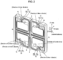
- Fig. 2 illustrates an operating state of sensing element 1.
- sensing element 1 When sensing element 1 is placed in a position that first arms 2 and second arms 4 are oriented along X axis and Y axis respectively within a space of the mutually orthogonal or substantially orthogonal axes of X, Y and Z, and an AC voltage of the resonance frequency is applied to first and second driving electrode units 17a and 17b, second arm 4 is driven and vibrated with the origin located at confronting portion 16 where driver unit 17 is formed.
- This causes weight 11 to vibrate in the direction that it faces second arm 4 (i.e., the direction of X axis where second arm 4 faces its own confronting portion 16, which is shown by a bidirectional arrow of solid and dotted lines).
- This causes all of four second arms 4 and four weights 11 to vibrate in harmony with each other in the same direction of facing respective second arms 4.
- the driving direction for vibrating this sensing element 1 is thus defined as to be X axis.
- first sensing electrode unit 19a and third sensing electrode unit 20a sense contraction
- second sensing electrode unit 19b and fourth sensing electrode unit 20b sense expansion of their respective confronting portions 16 of second arms 4, amongst the first through fourth sensing electrode units 19a, 19b, 20a and 20b formed on confronting portions 16 of second arms 4.
- first sensing electrode unit 19a, third sensing electrode unit 20a, second sensing electrode unit 19b and fourth sensing electrode unit 20b sense expansion and contraction inversely when the Coriolis force is generated in the direction shown by the dotted-line arrow.
- First through fourth sensing electrode units 19a, 19b, 20a and 20b thus output voltages responsive to sensed magnitudes of the expansion and the contraction, so as to detect the angular velocity based on these output voltages.
- First through fourth sensing electrode units 19a, 19b, 20a and 20b also sense these expansion and contraction, and detect the angular velocity in the same manner.
- first and second driving electrode units 17a, 17b, and first and second detecting electrode units 18a and 18b are formed. It is therefore possible that first through fourth sensing electrode units 19a, 19b, 20a and 20b are formed on second arms 4 where first and second driving electrode units 17a, 17b, and first and second detecting electrode units 18a and 18b are formed.
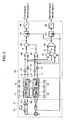
- Fig. 3 is a circuit block diagram of the angular velocity sensor.
- driver unit 17 and detector unit 18 formed on two mutually confronting second arms 4 (i.e., those at the upper side in Fig. 1 ) amongst four second arms 4 are connected to driver circuit unit 21.
- First sensor unit 19 and second sensor unit 20 formed on the other two of second arms 4 (i.e., those at the lower side in Fig. 1 ) are connected to detector circuit unit 25.
- the two sensor signals output from first sensing electrode unit 19a and second sensing electrode unit 19b constituting first sensor unit 19 are amplified individually by amplifiers 12 and 13. Using these two sensor signals, subtracter 30 outputs a first differential signal (at signal point "e"). At the same time, the two sensor signals amplified by amplifiers 12 and 13 are also distributed to adder 32, which outputs a first additional signal (at signal point "g") using these two distributed sensor signals.
- the two sensor signals output from third sensing electrode unit 20a and fourth sensing electrode unit 20b constituting second sensor unit 20 are amplified by amplifiers 14 and 15, and subtracter 34 outputs a second differential signal (at signal point "f) using these two sensor signals.
- the two sensor signals amplified by amplifiers 14 and 15 are distributed to adder 36, which outputs a second additional signal (at signal point "h") using these two distributed sensor signals.
- adder 38 outputs an additional signal (at signal point “i") by using the first differential signal output from subtracter 30 and the second differential signal output from subtracter 34.
- subtracter 40 outputs a subtraction signal (at signal point "j") by using the first additional signal output from adder 32 and the second additional signal output by adder 36.
- the additional signal and the subtraction signal are then detected by wave-detector circuits 42 and 44, and they are output through low-pass filters 46 and 48 as a first angular velocity signal and a second angular velocity signal.
- Angular velocities in a plurality of detecting axes can be hence detected by comparing values of these first and second angular velocity signals.
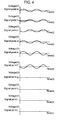
- Fig. 4 is an illustration of typical waveforms at the individual signal points when there is no angular velocity motion
- Fig. 5 is another illustration of typical waveforms at the individual signal points when there is an angular velocity motion around the Z axis
- Fig. 6 is still another illustration of typical waveforms at the individual signal points when there is an angular velocity motion around the Y axis.
- Fig. 5 and Fig. 6 illustrate specific waveforms abstracted to show only the Coriolis components.
- the above structure can hence enable a single unit of the sensing element to detect angular velocities around the two axes of detection since a value of the additional signal (i.e., the specific waveform at the signal point "i") based on the first differential signal and the second differential signal and a value of the differential signal (i.e., the specific waveform at the signal point "j") based on the first additional signal and the second additional signal are different with respect to each other when detecting the angular velocities around both the Z axis and the X axis among the three mutually orthogonal axes of X, Y and Z.
- a value of the additional signal i.e., the specific waveform at the signal point "i”
- a value of the differential signal i.e., the specific waveform at the signal point "j”
- differential signal i.e., the specific waveform at the signal point "j”
- additional signal i.e., the specific waveform at the signal point "i"
- the present invention makes it unnecessary to provide a mounting area for a plurality of sensing elements or a plurality of angular velocity sensors, but only a space appropriate for mounting a single sensing element, when detecting angular velocities of the plurality of axes, thereby achieving downsizing of a variety of electronic devices.
- failure diagnosis signal generator 50 supplies two failure diagnosis signals of same phase or opposite phase to first and second driving electrode units 17a and 17b when angular velocity motion is not present.
- detector circuit unit 25 compares a signal output from the additional signal and the differential signal with signals output in the normal state of bearing an angular velocity motion, and determines if they coincide with each other. It can be determined when these signals coincide that detector circuit unit 25 detects a pseudo angular velocity, and therefore no failure exists.
- the driving signal and the failure diagnosis signal have waveforms different in phase by 90 degrees.
- Fig. 7 is an illustration of the typical waveforms at the individual signal points S1 and S2 corresponding to the two failure diagnosis signals of opposite phase
- Fig. 8 is another illustration of typical waveforms at the individual signal points S1 and S2 corresponding to the two failure diagnosis signals of same phase.
- a value of the additional signal is output (i.e., the waveform at the signal point "i") based on the first differential signal and the second differential signal, but no value of differential signal is output (i.e., no waveform at the signal point "j") in the like manner as if there is an angular velocity motion only around the Z axis, when the two failure diagnosis signals are in the opposite phase.
- a value of the additional signal is not output (i.e., no waveform at the signal point "i") based on the first differential signal and the second differential signal, but only a value of the differential signal is output (i.e., the waveform at the signal point "j") in the like manner as if there is an angular velocity motion only around the Y axis, as shown in Fig. 8 .
- the invented structure is therefore capable of determining the presence or absence of any failure in the sensing element and the detector circuit unit by virtue of supplying the two failure diagnosis signals of the same phase or the opposite phase to first and second driving electrode units 17a and 17b in the driver unit, and detecting a pseudo angular velocity from the additional signal and the differential signal.
- first and second driving electrode units 17a, 17b, first and second detecting electrode units 18a, 18b, first through fourth sensing electrode units 19a, 19b, 20a and 20b are illustrated as being formed on confronting portions 16 of second arms 4. However, they may be formed on other positions than confronting portions 16 of second arms 4. For instance, all of first and second driving electrode units 17a, 17b, first and second detecting electrode units 18a, 18b, first through fourth sensing electrode units 19a, 19b, 20a and 20b can be formed on positions of four second arms 4 in the vicinity of supporting portion 6, or positions in parallel with first arms 2.
- Fig. 9 is a perspective view showing a sensing element of an angular velocity sensor according to another exemplary embodiment of the present invention
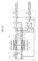
- Fig. 10 is a circuit block diagram of this angular velocity sensor.
- the sensing element can be configured as shown in Fig. 9 when first and second driving electrode units 17a, 17b, first and second detecting electrode units 18a, 18b, first through fourth sensing electrode units 19a, 19b, 20a and 20b are formed on the positions of four second arms 4 in the vicinity of supporting portion 6. Connections of the sensing element to driver circuit unit 21 and detector circuit unit 25 are as shown in Fig. 10 . Since these components operate in the similar manner as discussed above, their details will be skipped.
- one of second arms 4 is driven and vibrated with the origin located at the position near supporting portion 6, and it causes all of four second arms 4 and four weights 11 to vibrate in harmony with one another.
- the angular velocity sensor according to the present invention helps achieve downsizing of a variety of electronic devices, and it is therefore suitable for application to the variety of electronic devices since it does not require a large mounting area otherwise necessary for installation of a plurality of sensing elements or a plurality of angular velocity sensors.
Landscapes
- Engineering & Computer Science (AREA)
- Physics & Mathematics (AREA)
- General Physics & Mathematics (AREA)
- Radar, Positioning & Navigation (AREA)
- Remote Sensing (AREA)
- Signal Processing (AREA)
- Gyroscopes (AREA)
Abstract
Description
- The present invention relates to an angular velocity sensor for detecting angular velocity used in a variety of electronic devices for the purpose of controlling attitude, navigation and the like functions of movable bodies such as aircrafts, automobiles, robots, ships, vehicles and the like.
- Description is provided hereinafter of a conventional angular velocity sensor.
- The conventional angular velocity sensor detects an angular velocity by vibrating a sensing element of such a shape as a tuning fork, a letter H and a letter T, for example, and electrically detecting a distortion of the sensing element caused by a Coriolis force.
- When a vehicle is disposed on an X-Y plane between X axis and Y axis within a space of the mutually orthogonal axes of X, Y and Z, for instance, the angular velocity sensor for navigation device is required to detect angular velocities around the X axis and the Z axis of the vehicle.
- For detecting angular velocities of a plurality of axes (e.g., X axis, Y axis and Z axis) it has been the general practice in the past to use a plurality of angular velocity sensors, each corresponding to the respective axis of detection. In addition, a sensing element has been positioned vertically on the X-Y plane when detecting an angular rate around the Z axis.
-
Patent reference 1, for instance, is one of the prior art documents known to be related to the invention of the present application. - In the case of the above structure, however, it is necessary to provide a mounting area sufficient for installing a plurality of sensing elements or a plurality of angular velocity sensors on a mount board when detecting angular velocities of a plurality of axes, so that it is difficult to make downsizing of the variety of electronic devices.
- Patent Reference 1: Unexamined Japanese Patent Publication, No.
2001-208546 - The present invention is contrived to solve the above disadvantages, and to provide angular velocity sensors that enable downsizing of a variety of electronic devices since the invention makes it unnecessary to provide a large mounting area otherwise required for installation of a plurality of sensing elements or a plurality of angular velocity sensors even for detecting angular velocities of a plurality of axes.
- To achieve the object, the present invention provides a structure specifically comprising a driver circuit unit for supplying two driving signals to a driver unit, and a detector circuit unit for outputting a first differential signal according to two sensor signals output from a first sensor unit, a second differential signal according to two sensor signals output from a second sensor unit, a first additional signal according to the two sensor signals output from the first sensor unit, and a second additional signal according to the two sensor signals output from the second sensor unit, and detecting an angular velocity from an additional signal based on the first differential signal and the second differential signal and a differential signal based on the first additional signal and the second additional signal.
- The above structure enables a single unit of sensing element to detect angular velocities around two detecting axes since a value of the additional signal based on the first differential signal and the second differential signal and a value of the differential signal based on the first additional signal and the second additional signal are different with respect to each other when detecting the angular velocities around both the Z axis and the X axis among the three mutually orthogonal axes of X, Y and Z.
- Accordingly, this invention makes it unnecessary to provide a mounting area for installing a plurality of sensing elements or a plurality of angular velocity sensors, but only a space appropriate for mounting a single sensing element, when detecting angular velocities of the plurality of axes, thereby achieving downsizing of the variety of electronic devices.
-
-
Fig. 1 is a perspective view illustrating a sensing element of an angular velocity sensor according to one exemplary embodiment of the present invention; -
Fig. 2 is another view illustrating an operating state of the sensing element of the angular velocity sensor; -
Fig. 3 is a circuit block diagram of the angular velocity sensor; -
Fig. 4 is an illustration of typical waveforms at individual signal points when there is no angular velocity motion; -
Fig. 5 is an illustration of typical waveforms at the individual signal points when there is an angular velocity motion around the Z axis; -
Fig. 6 is an illustration of typical waveforms at the individual signal points when there is an angular velocity motion around the Y axis; -
Fig. 7 is an illustration of typical waveforms at the individual signal points in response to two failure diagnosis signals of opposite phase; -
Fig. 8 is an illustration of typical waveforms at the individual signal points in response to two failure diagnosis signals of same phase; -
Fig. 9 is a perspective view illustrating a sensing element of an angular velocity sensor according to another exemplary embodiment of the present invention; and -
Fig. 10 is a circuit block diagram of the above angular velocity sensor. -
- 1 Sensing element
- 2 First arm
- 4 Second arm
- 6 Supporting portion
- 8 Fixing arm
- 9 Fixing portion
- 10 Third arm
- 11 Weight
- 12, 13, 14 and 15 Amplifier
- 16 Confronting portion
- 17 Driver unit
- 17a First driving electrode unit
- 17b Second driving electrode unit
- 18 Detector unit
- 18a First detecting electrode unit
- 18b Second detecting electrode unit
- 19 First sensor unit
- 19a First sensing electrode unit
- 19b Second sensing electrode unit
- 20 Second sensor unit
- 20a Third sensing electrode unit
- 20b Fourth sensing electrode unit
- 21 Driver circuit unit
- 25 Detector circuit unit
- 30, 34 and 40 Subtracter
- 32, 36 and 38 Adder
- 42 and 44 Wave-detector circuit
- 46 and 48 Low-pass filter
- 50 Failure diagnosis signal generator
-
Fig. 1 is a perspective view illustrating a sensing element of an angular velocity sensor according to one exemplary embodiment of the present invention. - In
Fig. 1 , the angular velocity sensor in this exemplary embodiment of the invention includessensing element 1 for detecting an angular velocity. Thissensing element 1 has two orthogonally-configured arms, each consisting offirst arm 2 coupled tosecond arm 4 in a direction substantially orthogonal to each other. Sensingelement 1 also has supportingportion 6, which supports twofirst arms 2, and fixingarms 8 having one ends connected to supportingportion 6 and the other ends for fixation to a mount board (not shown). - Fixing
arms 8 have an orthogonally-configured arm structure consisting ofthird arms 10, each coupled to respective one offirst arms 2 in a direction substantially orthogonal to each other, and fixingportions 9 formed at both ends ofthird arms 10 are used for fixation to the mount board.Second arms 4 are bent back to form confrontingportions 16 in a manner that they face respective portions of their ownsecond arms 4, andweights 11 are connected to respective ends of confrontingportions 16. - In this
sensing element 1,first arms 2 offixing arms 8 and supportingportion 6 are formed substantially linearly so thatsecond arms 4 are oriented along the direction of Y axis when sensingelement 1 is disposed withfirst arms 2 in an orientation of X axis within a space of the three mutually orthogonal axes of X, Y and Z. - In addition, sensing
element 1 is provided withdriver unit 17 for drivingweights 11 into vibratory motion anddetector unit 18 for detecting a driving condition on confrontingportions 16 of two adjacentsecond arms 4 at one side (i.e., the upper side inFig. 1 ) amongst foursecond arms 4.Sensing element 1 is also provided withfirst sensor unit 19 andsecond sensor unit 20 for sensing distortion ofsecond arms 4 on confrontingportions 16 of two adjacentsecond arms 4 at the other side (i.e., the lower side inFig. 1 ). - This
driver unit 17 are electrode units intended for drivingweights 11 ofsecond arms 4, anddetector unit 18 are electrode units intended for detecting the driving condition ofsecond arms 4. First drivingelectrode unit 17a and seconddriving electrode unit 17b are formed on one ofsecond arms 4 in a confronting manner to composedriver unit 17, and first detectingelectrode unit 18a and second detectingelectrode unit 18b are formed on the othersecond arm 4 also in a confronting manner to composedetector unit 18. Each of these first and seconddriving electrode units electrode units -
First sensor unit 19 andsecond sensor unit 20 include electrode units for sensing distortion of twosecond arms 4. Firstsensing electrode unit 19a and secondsensing electrode unit 19b are formed on one ofsecond arms 4 in a confronting manner, and thirdsensing electrode unit 20a and fourthsensing electrode unit 20b are formed on the othersecond arm 4 also in a confronting manner to composefirst sensor unit 19 andsecond sensor unit 20 respectively. Each of these first through fourthsensing electrode units - The above-mentioned first and second
driving electrode units electrode units sensing electrode units - When an AC voltage of a resonance frequency is applied to first and second
driving electrode units second arm 4 is driven and vibrated with the origin located at confrontingportion 16 wheredriver unit 17 is formed. This causes all of foursecond arms 4 and fourweights 11 to vibrate in harmony with one another. Whensecond arms 4 are distorted due to an angular velocity motion, first through fourthsensing electrode units -
Fig. 2 illustrates an operating state of sensingelement 1. - When sensing
element 1 is placed in a position thatfirst arms 2 andsecond arms 4 are oriented along X axis and Y axis respectively within a space of the mutually orthogonal or substantially orthogonal axes of X, Y and Z, and an AC voltage of the resonance frequency is applied to first and seconddriving electrode units second arm 4 is driven and vibrated with the origin located at confrontingportion 16 wheredriver unit 17 is formed. This causesweight 11 to vibrate in the direction that it faces second arm 4 (i.e., the direction of X axis wheresecond arm 4 faces its own confrontingportion 16, which is shown by a bidirectional arrow of solid and dotted lines). At the same time, this causes all of foursecond arms 4 and fourweights 11 to vibrate in harmony with each other in the same direction of facing respectivesecond arms 4. The driving direction for vibrating thissensing element 1 is thus defined as to be X axis. - When an angular velocity motion occurs in this state in the direction of counterclockwise about the Z axis, for instance, it generates a Coriolis force affecting on
weights 11 in the direction orthogonal to the direction of vibration (i.e., directions of Coriolis force shown by a solid-line arrow and a dotted-line arrow), and this Coriolis force can produce distortion insecond arms 4 attributed to the angular velocity motion in counterclockwise about the Z axis. This Coriolis force acts in the direction ofY axis ofsensing element 1. - When the Coriolis force is generated in the direction shown by the solid-line arrow, first
sensing electrode unit 19a and thirdsensing electrode unit 20a sense contraction, and secondsensing electrode unit 19b and fourthsensing electrode unit 20b sense expansion of their respective confrontingportions 16 ofsecond arms 4, amongst the first through fourthsensing electrode units portions 16 ofsecond arms 4. On the other hand, firstsensing electrode unit 19a, thirdsensing electrode unit 20a, secondsensing electrode unit 19b and fourthsensing electrode unit 20b sense expansion and contraction inversely when the Coriolis force is generated in the direction shown by the dotted-line arrow. - First through fourth
sensing electrode units - When an angular velocity motion occurs in the direction of clockwise about the Z axis, on the other hand, confronting
portions 16 ofsecond arms 4 expand and contract in a manner diametrically opposite to the case the angular velocity motion occurs counterclockwise about the Z axis. First through fourthsensing electrode units - When an angular velocity motion occurs around the Y axis, it also generates a Coriolis force affecting on
weights 11 in the direction orthogonal to the direction of vibration (i.e., the direction of Z axis). The Coriolis force then produces distortion insecond arms 4 attributed to the angular velocity motion about the Y axis, and first through fourthsensing electrode units portions 16 ofsecond arms 4 and detect the angular velocity in the like manner. - The distortion generated by the angular velocity motion in any of the Z axis and Y axis also occurs in
second arms 4 where first and seconddriving electrode units electrode units sensing electrode units second arms 4 where first and seconddriving electrode units electrode units -
Fig. 3 is a circuit block diagram of the angular velocity sensor. - In
Fig. 3 ,driver unit 17 anddetector unit 18 formed on two mutually confronting second arms 4 (i.e., those at the upper side inFig. 1 ) amongst foursecond arms 4 are connected todriver circuit unit 21.First sensor unit 19 andsecond sensor unit 20 formed on the other two of second arms 4 (i.e., those at the lower side inFig. 1 ) are connected todetector circuit unit 25. - Description is now provided of a process carried out in
detector circuit unit 25 for two sensor signals output fromfirst sensor unit 19 andsecond sensor unit 20. - The two sensor signals output from first
sensing electrode unit 19a and secondsensing electrode unit 19b constitutingfirst sensor unit 19 are amplified individually byamplifiers subtracter 30 outputs a first differential signal (at signal point "e"). At the same time, the two sensor signals amplified byamplifiers - The two sensor signals output from third
sensing electrode unit 20a and fourthsensing electrode unit 20b constitutingsecond sensor unit 20 are amplified byamplifiers subtracter 34 outputs a second differential signal (at signal point "f) using these two sensor signals. At the same time, the two sensor signals amplified byamplifiers - Furthermore, adder 38 outputs an additional signal (at signal point "i") by using the first differential signal output from
subtracter 30 and the second differential signal output fromsubtracter 34. In addition,subtracter 40 outputs a subtraction signal (at signal point "j") by using the first additional signal output fromadder 32 and the second additional signal output byadder 36. - The additional signal and the subtraction signal are then detected by wave-
detector circuits pass filters - Angular velocities in a plurality of detecting axes can be hence detected by comparing values of these first and second angular velocity signals.
- In operating conditions of this
sensing element 1 here, typical waveforms found at the individual signal points "a" to "j" ofdetector circuit unit 25 are as illustrated inFig. 4 through Fig. 6 . -
Fig. 4 is an illustration of typical waveforms at the individual signal points when there is no angular velocity motion,Fig. 5 is another illustration of typical waveforms at the individual signal points when there is an angular velocity motion around the Z axis, andFig. 6 is still another illustration of typical waveforms at the individual signal points when there is an angular velocity motion around the Y axis.Fig. 5 andFig. 6 , in particular, illustrate specific waveforms abstracted to show only the Coriolis components. - When there is no angular velocity motion, signal waves do not appear at both the signal points "i" and "j" as shown in
Fig. 4 , indicating no output of the first and second angular velocity signals. - When there is an angular velocity motion around the Z axis, a signal wave is output at the signal point "i", but no signal wave at the signal point "j" as shown in
Fig. 5 , indicating that the second angular velocity signal is not output. - When there is an angular velocity motion around the Y axis, no signal wave appears at the signal point "i", indicating that the first angular velocity signal is not output, but a signal wave is output at the signal point "j" as shown in
Fig. 6 . - It is thus possible to detect various states of bearing the angular velocity motion distinctively since the specific signal waveforms produced at the signal points "i" and "j" are different among the cases when the angular velocity motion occurs around the Y axis, around the Z axis and when there is no angular velocity motion at all.
- The above structure can hence enable a single unit of the sensing element to detect angular velocities around the two axes of detection since a value of the additional signal (i.e., the specific waveform at the signal point "i") based on the first differential signal and the second differential signal and a value of the differential signal (i.e., the specific waveform at the signal point "j") based on the first additional signal and the second additional signal are different with respect to each other when detecting the angular velocities around both the Z axis and the X axis among the three mutually orthogonal axes of X, Y and Z.
- More specifically, there is not any output value of differential signal (i.e., the specific waveform at the signal point "j") based on the first additional signal and the second additional signal when an angular velocity motion occurs only around the Z axis, and there is not any output value of additional signal (i.e., the specific waveform at the signal point "i") based on the first differential signal and the second differential signal when an angular velocity motion occurs only around the Y axis. It is therefore determinable that an angular velocity motion takes place around both of the Y axis and the Z axis at the same time if there are outputs of specific waveforms at both the signal points "i" and "j", so as to make angular velocities detectable around the two axes of detection simultaneously.
- It is also possible to distinguish the absence of angular velocity motion from the presence thereof since there is neither an output value of the additional signal (i.e., the specific waveform at the signal point "i") nor an output value of differential signal (i.e., the specific waveform at the signal point "j") based on the first differential signal and the second differential signal when there is no angular velocity motion.
- In the case when a value of the additional signal (at the signal point "i") based on the first differential signal and the second differential signal is different from a value of the differential signal (at the signal point "j") and if they have a certain ratio of relation, it is then possible to achieve a similar effect by converting this ratio.
- Accordingly, the present invention makes it unnecessary to provide a mounting area for a plurality of sensing elements or a plurality of angular velocity sensors, but only a space appropriate for mounting a single sensing element, when detecting angular velocities of the plurality of axes, thereby achieving downsizing of a variety of electronic devices.
- Description is provided next of a process carried out in the circuit for diagnosing failures.
- In
driver circuit unit 21 ofFig. 3 , failurediagnosis signal generator 50 supplies two failure diagnosis signals of same phase or opposite phase to first and seconddriving electrode units detector circuit unit 25 compares a signal output from the additional signal and the differential signal with signals output in the normal state of bearing an angular velocity motion, and determines if they coincide with each other. It can be determined when these signals coincide thatdetector circuit unit 25 detects a pseudo angular velocity, and therefore no failure exists. - It is preferable in this case that the driving signal and the failure diagnosis signal have waveforms different in phase by 90 degrees.
- In the failure diagnostic mode here, typical waveforms found at the individual signal points S1 and S2 of
driver circuit unit 21 and the signal points "a" to "j" ofdetector circuit unit 25 are as illustrated inFig. 7 andFig. 8 . -
Fig. 7 is an illustration of the typical waveforms at the individual signal points S1 and S2 corresponding to the two failure diagnosis signals of opposite phase, andFig. 8 is another illustration of typical waveforms at the individual signal points S1 and S2 corresponding to the two failure diagnosis signals of same phase. - As shown in
Fig. 7 , a value of the additional signal is output (i.e., the waveform at the signal point "i") based on the first differential signal and the second differential signal, but no value of differential signal is output (i.e., no waveform at the signal point "j") in the like manner as if there is an angular velocity motion only around the Z axis, when the two failure diagnosis signals are in the opposite phase. - When the two failure diagnosis signals are in the same phase, on the other hand, a value of the additional signal is not output (i.e., no waveform at the signal point "i") based on the first differential signal and the second differential signal, but only a value of the differential signal is output (i.e., the waveform at the signal point "j") in the like manner as if there is an angular velocity motion only around the Y axis, as shown in
Fig. 8 . - The invented structure is therefore capable of determining the presence or absence of any failure in the sensing element and the detector circuit unit by virtue of supplying the two failure diagnosis signals of the same phase or the opposite phase to first and second
driving electrode units - In this exemplary embodiment of the invention, first and second
driving electrode units electrode units sensing electrode units portions 16 ofsecond arms 4. However, they may be formed on other positions than confrontingportions 16 ofsecond arms 4. For instance, all of first and seconddriving electrode units electrode units sensing electrode units second arms 4 in the vicinity of supportingportion 6, or positions in parallel withfirst arms 2. -
Fig. 9 is a perspective view showing a sensing element of an angular velocity sensor according to another exemplary embodiment of the present invention, andFig. 10 is a circuit block diagram of this angular velocity sensor. - The sensing element can be configured as shown in
Fig. 9 when first and seconddriving electrode units electrode units sensing electrode units second arms 4 in the vicinity of supportingportion 6. Connections of the sensing element todriver circuit unit 21 anddetector circuit unit 25 are as shown inFig. 10 . Since these components operate in the similar manner as discussed above, their details will be skipped. - In this instance, one of
second arms 4 is driven and vibrated with the origin located at the position near supportingportion 6, and it causes all of foursecond arms 4 and fourweights 11 to vibrate in harmony with one another. - The angular velocity sensor according to the present invention helps achieve downsizing of a variety of electronic devices, and it is therefore suitable for application to the variety of electronic devices since it does not require a large mounting area otherwise necessary for installation of a plurality of sensing elements or a plurality of angular velocity sensors.
Claims (5)
- An angular velocity sensor comprising:a sensing element including:a plurality of arms;a driver unit formed on one of the arms for driving the arm to vibrate; anda first sensor unit and a second sensor unit formed on the arms for sensing distortion of the arms;a driver circuit unit connected to the driver unit for driving the driver unit; anda detector circuit unit connected to the first sensor unit and the second sensor unit for detecting an angular velocity,wherein the driver circuit unit supplies two driving signals to the driver unit, andwherein the detector circuit unit has functions of:outputting a first differential signal according to two sensor signals output from the first sensor unit;outputting a second differential signal according to two sensor signals output from the second sensor unit;outputting a first additional signal according to the two sensor signals output from the first sensor unit;outputting a second additional signal according to the two sensor signals output from the second sensor unit; anddetecting the angular velocity from an additional signal obtained based on the first differential signal and the second differential signal, and a differential signal obtained based on the first additional signal and the second additional signal.
- The angular velocity sensor of claim 1 further comprising:a failure diagnosis unit for supplying two failure diagnosis signals of same phase or opposite phase to the driver unit, and detecting a pseudo angular velocity from the additional signal and the differential signal.
- The angular velocity sensor of claim 2,
wherein the driving signal and the failure diagnosis signal have waveforms different in phase by 90 degrees with respect to each other. - The angular velocity sensor of claim 1,
wherein the plurality of arms includes:two orthogonally-configured arms, each consisting of a first arm coupled to a second arm in a direction generally orthogonal to each other,a supporting portion supporting the two first arms,a fixing arm connected to the supporting portion and fixed to a mount board, andweights provided at respective ends of the second arms;wherein the two second arms are configured to confront each other; and
the first sensor unit is formed on one of the second arms and the second sensor unit is formed on the other of the second arms. - The angular velocity sensor of claim 4,wherein the first sensor unit includes a first sensing electrode unit and a second sensing electrode unit, each having a top electrode and a bottom electrode with a piezoelectric element interposed therebetween;the second sensor unit includes a third sensing electrode unit and a fourth sensing electrode unit, each having a top electrode and a bottom electrode with a piezoelectric element interposed therebetween;the first sensing electrode unit and the second sensing electrode unit are formed on one of the second arms in a confronting manner, and output two sensor signals; andthe third sensing electrode unit and the fourth sensing electrode unit are formed on the other of the second arms in a confronting manner, and output two sensor signals.
Applications Claiming Priority (3)
| Application Number | Priority Date | Filing Date | Title |
|---|---|---|---|
| JP2006223803 | 2006-08-21 | ||
| JP2006223804 | 2006-08-21 | ||
| PCT/JP2007/065395 WO2008023566A1 (en) | 2006-08-21 | 2007-08-07 | Angular velocity sensor |
Publications (2)
| Publication Number | Publication Date |
|---|---|
| EP2063224A1 true EP2063224A1 (en) | 2009-05-27 |
| EP2063224A4 EP2063224A4 (en) | 2012-05-09 |
Family
ID=39106653
Family Applications (1)
| Application Number | Title | Priority Date | Filing Date |
|---|---|---|---|
| EP07792064A Withdrawn EP2063224A4 (en) | 2006-08-21 | 2007-08-07 | ANGULAR SPEED SENSOR |
Country Status (4)
| Country | Link |
|---|---|
| US (1) | US8117913B2 (en) |
| EP (1) | EP2063224A4 (en) |
| JP (1) | JP5206409B2 (en) |
| WO (1) | WO2008023566A1 (en) |
Cited By (2)
| Publication number | Priority date | Publication date | Assignee | Title |
|---|---|---|---|---|
| EP2330381A4 (en) * | 2008-10-07 | 2012-07-04 | Panasonic Corp | ANGULAR SPEED SENSOR ELEMENT, ANGULAR SPEED SENSOR, AND ANGULAR SPEED SENSOR UNIT USING ALL OF THE ANGULAR SPEED SENSOR ELEMENT, AND SIGNAL DETECTION METHOD FOR ANGULAR SPEED SENSOR UNIT |
| CN104448752A (en) * | 2013-09-17 | 2015-03-25 | 比亚迪股份有限公司 | Polymer article and ink composition and surface selective metallization method |
Families Citing this family (18)
| Publication number | Priority date | Publication date | Assignee | Title |
|---|---|---|---|---|
| US20090064783A1 (en) | 2006-01-24 | 2009-03-12 | Matsushita Electric Industrial Co., Ltd. | Inertial force sensor |
| WO2008035683A1 (en) * | 2006-09-21 | 2008-03-27 | Panasonic Corporation | Angular velocity sensor |
| JP2008076265A (en) * | 2006-09-22 | 2008-04-03 | Matsushita Electric Ind Co Ltd | Inertial force sensor |
| WO2008059757A1 (en) * | 2006-11-14 | 2008-05-22 | Panasonic Corporation | Sensor |
| US8117914B2 (en) * | 2007-02-20 | 2012-02-21 | Panasonic Corporation | Inertia force sensor and composite sensor for detecting inertia force |
| JP5407259B2 (en) * | 2008-10-07 | 2014-02-05 | パナソニック株式会社 | Angular velocity sensor element |
| WO2010073576A1 (en) * | 2008-12-26 | 2010-07-01 | パナソニック株式会社 | Angular velocity sensor |
| EP2385343B1 (en) * | 2009-02-13 | 2018-07-25 | Panasonic Intellectual Property Management Co., Ltd. | Inertial force sensor and detecting element used for same |
| US9301975B2 (en) | 2009-05-01 | 2016-04-05 | Biocardia, Inc. | Method of preparing autologous cells and method of use for therapy |
| US9097524B2 (en) | 2009-09-11 | 2015-08-04 | Invensense, Inc. | MEMS device with improved spring system |
| US8534127B2 (en) | 2009-09-11 | 2013-09-17 | Invensense, Inc. | Extension-mode angular velocity sensor |
| JP5131491B2 (en) * | 2010-02-24 | 2013-01-30 | セイコーエプソン株式会社 | Gyro module |
| JP2011220997A (en) * | 2010-03-26 | 2011-11-04 | Seiko Epson Corp | Physical quantity detection element, physical quantity detection device, and electronic device |
| US20140238129A1 (en) * | 2011-10-24 | 2014-08-28 | Panasonic Corporation | Angular velocity sensor and detection element used in same |
| JP5831647B2 (en) * | 2012-11-19 | 2015-12-09 | 株式会社村田製作所 | Angular velocity detector |
| US10466068B2 (en) * | 2017-01-23 | 2019-11-05 | Georgia Tech Research Corporation | Systems and methods for operation of vibratory gyroscopes |
| WO2021261557A1 (en) | 2020-06-24 | 2021-12-30 | パナソニックIpマネジメント株式会社 | Inertial force sensor |
| EP4215872B1 (en) | 2022-01-25 | 2025-01-22 | Commissariat à l'Energie Atomique et aux Energies Alternatives | 3-axis gyroscope with improved performance |
Family Cites Families (39)
| Publication number | Priority date | Publication date | Assignee | Title |
|---|---|---|---|---|
| JPH05240874A (en) * | 1991-12-06 | 1993-09-21 | Canon Inc | Angular velocity sensor |
| JP3323361B2 (en) * | 1995-05-29 | 2002-09-09 | アルプス電気株式会社 | Vibratory gyroscope |
| SE9500729L (en) * | 1995-02-27 | 1996-08-28 | Gert Andersson | Apparatus for measuring angular velocity in single crystalline material and method for making such |
| JP3492010B2 (en) * | 1995-03-29 | 2004-02-03 | キヤノン株式会社 | Vibrating gyroscope and vibration isolator |
| JPH08152328A (en) * | 1995-07-04 | 1996-06-11 | Nippondenso Co Ltd | Angular speed sensor and its using method |
| JPH09105634A (en) * | 1995-10-12 | 1997-04-22 | Nippon Soken Inc | Angular velocity sensor |
| JPH09178492A (en) * | 1995-12-27 | 1997-07-11 | Kyocera Corp | Piezoelectric vibrator |
| JPH1047966A (en) * | 1996-07-31 | 1998-02-20 | Aisin Seiki Co Ltd | Angular velocity sensor |
| JP3336605B2 (en) * | 1997-02-12 | 2002-10-21 | トヨタ自動車株式会社 | Angular velocity sensor |
| JP3355998B2 (en) * | 1997-05-16 | 2002-12-09 | 株式会社村田製作所 | Vibrating gyro |
| JP4004129B2 (en) * | 1998-02-09 | 2007-11-07 | マイクロストーン株式会社 | Motion sensor |
| JP4112684B2 (en) * | 1998-06-01 | 2008-07-02 | シチズンホールディングス株式会社 | Vibrating gyro |
| JP2000074673A (en) * | 1998-08-27 | 2000-03-14 | Miyota Kk | Compound movement sensor |
| US6418789B1 (en) * | 1999-02-26 | 2002-07-16 | Murata Manufacturing Co., Ltd. | Vibrating gyroscope |
| JP3998049B2 (en) * | 1999-09-13 | 2007-10-24 | 芳明 加藤 | Motion sensor vibrator and vibratory gyroscope |
| JP2001208546A (en) | 1999-11-16 | 2001-08-03 | Matsushita Electric Ind Co Ltd | Angular velocity sensor |
| JP2001194155A (en) * | 2000-01-13 | 2001-07-19 | Yoshiro Tomikawa | Motion sensor |
| JP4552253B2 (en) * | 2000-02-28 | 2010-09-29 | パナソニック株式会社 | Angular velocity sensor |
| JP2002139322A (en) | 2000-10-31 | 2002-05-17 | Murata Mfg Co Ltd | Self-diagnosable method of vibrating gyro and vibrating gyro and electronic device using the same |
| US6675630B2 (en) * | 2001-08-17 | 2004-01-13 | The Boeing Company | Microgyroscope with electronic alignment and tuning |
| JP4147784B2 (en) * | 2001-10-09 | 2008-09-10 | 富士通株式会社 | Angular velocity sensor |
| JP2004077351A (en) * | 2002-08-21 | 2004-03-11 | Matsushita Electric Ind Co Ltd | Angular velocity sensor |
| JP4163031B2 (en) * | 2003-03-28 | 2008-10-08 | 日本電波工業株式会社 | Tuning fork type angular velocity sensor |
| US6845665B2 (en) * | 2003-04-28 | 2005-01-25 | Analog Devices, Inc. | Micro-machined multi-sensor providing 2-axes of acceleration sensing and 1-axis of angular rate sensing |
| US6880400B1 (en) * | 2003-05-23 | 2005-04-19 | The United States Of America As Represented By The Secretary Of The Navy | Phase synchronized array of non-identical oscillators using coupling network |
| JP4599848B2 (en) | 2004-02-18 | 2010-12-15 | パナソニック株式会社 | Angular velocity sensor |
| JP2005283481A (en) * | 2004-03-30 | 2005-10-13 | Denso Corp | Sensor system |
| JP2005283402A (en) * | 2004-03-30 | 2005-10-13 | Fujitsu Media Device Kk | Inertial sensor |
| US7640803B1 (en) * | 2004-05-26 | 2010-01-05 | Siimpel Corporation | Micro-electromechanical system inertial sensor |
| JP2006030125A (en) | 2004-07-21 | 2006-02-02 | Fujitsu Media Device Kk | Angular velocity sensor |
| JP2006105756A (en) | 2004-10-05 | 2006-04-20 | Matsushita Electric Ind Co Ltd | Angular velocity sensor |
| JP4543869B2 (en) * | 2004-10-15 | 2010-09-15 | 株式会社デンソー | Sensor circuit in vibration type angular velocity sensor |
| JP4687085B2 (en) * | 2004-12-03 | 2011-05-25 | パナソニック株式会社 | Compound sensor |
| JP2006266969A (en) * | 2005-03-25 | 2006-10-05 | Nec Tokin Corp | Tuning fork type piezo-electric oscillating gyroscope |
| US7886598B2 (en) * | 2005-08-08 | 2011-02-15 | Northrop Grumman Guidance And Electronics Company, Inc. | Vibratory gyro bias error cancellation using mode reversal |
| JP4702942B2 (en) * | 2005-10-14 | 2011-06-15 | Necトーキン株式会社 | Vibrating gyro element and vibrating gyro |
| JP2007256235A (en) | 2006-03-27 | 2007-10-04 | Matsushita Electric Ind Co Ltd | Inertial force sensor |
| JP2007327758A (en) * | 2006-06-06 | 2007-12-20 | Nec Tokin Corp | Piezoelectric single-crystal oscillator and piezoelectric vibration gyroscope |
| JP4893335B2 (en) * | 2007-01-26 | 2012-03-07 | セイコーエプソン株式会社 | Gyro module |
-
2007
- 2007-08-07 JP JP2008530847A patent/JP5206409B2/en not_active Expired - Fee Related
- 2007-08-07 EP EP07792064A patent/EP2063224A4/en not_active Withdrawn
- 2007-08-07 WO PCT/JP2007/065395 patent/WO2008023566A1/en not_active Ceased
- 2007-08-07 US US12/377,327 patent/US8117913B2/en not_active Expired - Fee Related
Cited By (5)
| Publication number | Priority date | Publication date | Assignee | Title |
|---|---|---|---|---|
| EP2330381A4 (en) * | 2008-10-07 | 2012-07-04 | Panasonic Corp | ANGULAR SPEED SENSOR ELEMENT, ANGULAR SPEED SENSOR, AND ANGULAR SPEED SENSOR UNIT USING ALL OF THE ANGULAR SPEED SENSOR ELEMENT, AND SIGNAL DETECTION METHOD FOR ANGULAR SPEED SENSOR UNIT |
| US8561467B2 (en) | 2008-10-07 | 2013-10-22 | Panasonic Corporation | Angular velocity sensor element, angular velocity sensor and angular velocity sensor unit both using angular velocity sensor element, and signal detecting method for angular velocity sensor unit |
| USRE46514E1 (en) | 2008-10-07 | 2017-08-15 | Panasonic Corporation | Angular velocity sensor element, angular velocity sensor and angular velocity sensor unit both using angular velocity sensor element, and signal detecting method for angular velocity sensor unit |
| CN104448752A (en) * | 2013-09-17 | 2015-03-25 | 比亚迪股份有限公司 | Polymer article and ink composition and surface selective metallization method |
| CN104448752B (en) * | 2013-09-17 | 2017-01-18 | 比亚迪股份有限公司 | Polymer article and ink composition and surface selective metallization method |
Also Published As
| Publication number | Publication date |
|---|---|
| WO2008023566A1 (en) | 2008-02-28 |
| US20100218604A1 (en) | 2010-09-02 |
| US8117913B2 (en) | 2012-02-21 |
| JPWO2008023566A1 (en) | 2010-01-07 |
| EP2063224A4 (en) | 2012-05-09 |
| JP5206409B2 (en) | 2013-06-12 |
Similar Documents
| Publication | Publication Date | Title |
|---|---|---|
| US8117913B2 (en) | Angular velocity sensor | |
| US20090320594A1 (en) | Inertia force sensor | |
| US8122766B2 (en) | Inertia force sensor | |
| US8074517B2 (en) | Inertia force sensor | |
| EP2385343B1 (en) | Inertial force sensor and detecting element used for same | |
| JP4687085B2 (en) | Compound sensor | |
| US20100011859A1 (en) | Angular velocity sensor | |
| JP4858215B2 (en) | Compound sensor | |
| JP2008190972A (en) | Angular velocity sensor | |
| JP5125138B2 (en) | Compound sensor | |
| JP2008076263A (en) | Compound sensor | |
| JP2006226802A (en) | Compound sensor | |
| JP2008046056A (en) | Angular velocity sensor | |
| JP2008122263A (en) | Angular velocity sensor | |
| JP2008122262A (en) | Angular velocity sensor | |
| JP2009250955A (en) | Inertial force sensor | |
| JP2008209253A (en) | Angular velocity sensor | |
| JP2007198779A (en) | Inertial force sensor | |
| JP2007198774A (en) | Inertial force sensor | |
| JP2007198780A (en) | Inertial force sensor | |
| JP2008261772A (en) | Inertial force sensor |
Legal Events
| Date | Code | Title | Description |
|---|---|---|---|
| PUAI | Public reference made under article 153(3) epc to a published international application that has entered the european phase |
Free format text: ORIGINAL CODE: 0009012 |
|
| 17P | Request for examination filed |
Effective date: 20090210 |
|
| AK | Designated contracting states |
Kind code of ref document: A1 Designated state(s): AT BE BG CH CY CZ DE DK EE ES FI FR GB GR HU IE IS IT LI LT LU LV MC MT NL PL PT RO SE SI SK TR |
|
| AX | Request for extension of the european patent |
Extension state: AL BA HR MK RS |
|
| DAX | Request for extension of the european patent (deleted) | ||
| RBV | Designated contracting states (corrected) |
Designated state(s): DE FR GB |
|
| A4 | Supplementary search report drawn up and despatched |
Effective date: 20120410 |
|
| 17Q | First examination report despatched |
Effective date: 20130926 |
|
| STAA | Information on the status of an ep patent application or granted ep patent |
Free format text: STATUS: THE APPLICATION IS DEEMED TO BE WITHDRAWN |
|
| 18D | Application deemed to be withdrawn |
Effective date: 20160402 |