JP2006226802A - Compound sensor - Google Patents

Compound sensor Download PDF

Info

Publication number
JP2006226802A
JP2006226802A JP2005040145A JP2005040145A JP2006226802A JP 2006226802 A JP2006226802 A JP 2006226802A JP 2005040145 A JP2005040145 A JP 2005040145A JP 2005040145 A JP2005040145 A JP 2005040145A JP 2006226802 A JP2006226802 A JP 2006226802A
Authority
JP
Japan
Prior art keywords
vibration
fixed base
acceleration
composite sensor
sensor according
Prior art date
Legal status (The legal status is an assumption and is not a legal conclusion. Google has not performed a legal analysis and makes no representation as to the accuracy of the status listed.)
Pending
Application number
JP2005040145A
Other languages
Japanese (ja)
Inventor
Jiro Terada
二郎 寺田
Takami Ishida
貴巳 石田
Tetsuo Kawasaki
哲生 川崎
Current Assignee (The listed assignees may be inaccurate. Google has not performed a legal analysis and makes no representation or warranty as to the accuracy of the list.)
Panasonic Holdings Corp
Original Assignee
Matsushita Electric Industrial Co Ltd
Priority date (The priority date is an assumption and is not a legal conclusion. Google has not performed a legal analysis and makes no representation as to the accuracy of the date listed.)
Filing date
Publication date
Application filed by Matsushita Electric Industrial Co Ltd filed Critical Matsushita Electric Industrial Co Ltd
Priority to JP2005040145A priority Critical patent/JP2006226802A/en
Publication of JP2006226802A publication Critical patent/JP2006226802A/en
Pending legal-status Critical Current

Links

Images

Abstract

<P>PROBLEM TO BE SOLVED: To provide a compound sensor for achieving miniaturization of a mounting substrate by compounding an angular speed sensor and an acceleration sensor to reduce a mounting area without needing the mounting area of the angular speed sensor and the mounting area of the acceleration sensor. <P>SOLUTION: The compound sensor having the angular speed sensor and the acceleration sensor is provided with two cone parts 8 connected to a fixing base part 4, a first vibrating element 10 for connecting one end to one cone part 8 and connecting the other end to the other cone part 8, and a second vibrating element 12 for connecting one end to the cone part 8. The first vibrating element 10 and the second vibrating element 12 are driven and vibrated, and drive vibration of the first vibrating element 10 changed by being caused by movement of the cone part 8 is detected to detect an acceleration. Curvature vibration of the second vibrating element 12 changed by being caused by Coriolis force is detected to detect an angular speed. <P>COPYRIGHT: (C)2006,JPO&NCIPI

Description

本発明は、航空機、自動車、ロボット、船舶、車両等の移動体の姿勢制御やナビゲーション等、各種電子機器に用いる角速度センサおよび加速度センサを複合した複合センサに関するものである。   The present invention relates to a composite sensor that combines an angular velocity sensor and an acceleration sensor used in various electronic devices such as attitude control and navigation of moving bodies such as aircraft, automobiles, robots, ships, and vehicles.

以下、従来の複合センサについて説明する。   Hereinafter, a conventional composite sensor will be described.

従来の複合センサは、角速度センサと加速度センサとを実装基板に各々実装して複合センサとしていた。   A conventional composite sensor is a composite sensor in which an angular velocity sensor and an acceleration sensor are each mounted on a mounting substrate.

従来の角速度センサは、例えば、音さ形状やH形状やT形状等、各種の形状の振動子を振動させて、コリオリ力の発生に伴う振動子の歪を電気的に検知して角速度を検出する。   Conventional angular velocity sensors, for example, vibrate vibrators of various shapes such as sound shape, H shape, T shape, etc., and electrically detect distortion of the vibrator accompanying the generation of Coriolis force to detect angular velocity To do.

また、従来の加速度センサは、錘部を有し、加速度に伴う錘部の可動を、可動前と比較検知して加速度を検出する。   Moreover, the conventional acceleration sensor has a weight part, and detects acceleration by comparing and detecting the movement of the weight part accompanying the acceleration with that before the movement.

このような角速度センサや加速度センサは、車両に搭載したナビゲーション装置や車両制御装置等に用いられる。   Such angular velocity sensors and acceleration sensors are used in navigation devices and vehicle control devices mounted on vehicles.

なお、この出願の発明に関連する先行技術文献情報としては、例えば、特許文献1および特許文献2が知られている。
特開2001−208546号公報 特開2001−74767号公報
For example, Patent Document 1 and Patent Document 2 are known as prior art document information related to the invention of this application.
JP 2001-208546 A JP 2001-74767 A

上記構成の複合センサは、角速度センサと加速度センサとを各々実装基板に実装したものであり、角速度センサの実装面積と加速度センサの実装面積とを確保する必要があり、実装基板の小型化を図れないという問題点を有していた。   The composite sensor having the above-described configuration is obtained by mounting an angular velocity sensor and an acceleration sensor on each mounting board, and it is necessary to secure a mounting area for the angular velocity sensor and a mounting area for the acceleration sensor, so that the mounting board can be reduced in size. Had the problem of not.

本発明は上記問題点を解決し、角速度センサの実装面積と加速度センサの実装面積とを必要とせず、角速度センサと加速度センサとを複合して実装面積を低減し、実装基板の小型化を図った複合センサを提供することを目的としている。   The present invention solves the above-described problems, and does not require the mounting area of the angular velocity sensor and the mounting area of the acceleration sensor, but reduces the mounting area by combining the angular velocity sensor and the acceleration sensor, thereby reducing the size of the mounting board. It aims to provide a combined sensor.

上記目的を達成するために本発明は、特に、固定基部に連結した2つの錘部と、一方の前記錘部に一端を連結するとともに他方の前記錘部に他端を連結した第1振動素子と、前記錘部に一端を連結した第2振動素子とを設け、前記第1振動素子および前記第2振動素子を互いに駆動振動させ、前記錘部の可動に起因して変化する前記第1振動素子の駆動振動を検知して加速度を検出するとともに、コリオリ力に起因して変化する前記第2振動素子の屈曲振動を検知して角速度を検出する構成としたものである。   In order to achieve the above object, the present invention particularly relates to two weight parts connected to a fixed base, and a first vibration element having one end connected to one of the weight parts and the other end connected to the other weight part. And a second vibration element having one end connected to the weight portion, wherein the first vibration element and the second vibration element are driven to vibrate with each other, and the first vibration changes due to the movement of the weight portion. The driving vibration of the element is detected to detect acceleration, and the angular vibration is detected by detecting the bending vibration of the second vibrating element that changes due to the Coriolis force.

上記構成により、固定基部に連結した2つの錘部と、一方の錘部に一端を連結するとともに、他方の錘部に他端を連結した第1振動素子と、錘部に一端を連結した第2振動素子とを設け、これら第1振動素子および第2振動素子を互いに駆動振動させるので、加速度センサとしては、錘部の可動に起因して変化する第1振動素子の駆動振動を検知して加速度を検出することができ、角速度センサとしては、第2振動素子の屈曲振動を検知して角速度を検出することができる。   With the above configuration, the first and second weight parts connected to the fixed base, the first vibration element having one end connected to one weight part and the other end connected to the other weight part, and the first connected to the weight part. Since the first vibration element and the second vibration element are driven to vibrate with each other, the acceleration sensor detects the drive vibration of the first vibration element that changes due to the movement of the weight portion. The acceleration can be detected, and the angular velocity sensor can detect the angular velocity by detecting the bending vibration of the second vibration element.

すなわち、角速度センサと加速度センサとを複合でき、実装面積を低減して実装基板の小型化を図ることができる。   That is, the angular velocity sensor and the acceleration sensor can be combined, and the mounting area can be reduced and the mounting substrate can be downsized.

以下、実施の形態を用いて、本発明の全請求項に記載の発明について、図面を参照しながら説明する。   Hereinafter, the invention described in all claims of the present invention will be described using embodiments with reference to the drawings.

図1は本発明の一実施の形態におけるケース未装着の複合センサの斜視図、図2は図1のA部の斜視図、図3は図2のA−A断面図、図4は図1のB部の斜視図、図5は図4のA−A断面図、図6は図4のB−B断面図、図7は図1のA部の駆動状態と動作状態を示す斜視図、図8は加速度検出回路図、図9は第1振動素子の駆動時における駆動信号の波形図、図10は図1のB部の駆動状態を示す斜視図、図11は図1のB部の動作状態を示す斜視図、図12は図1のB部の駆動状態を示す斜視図、図13は角速度検出回路図である。   1 is a perspective view of a composite sensor without a case according to an embodiment of the present invention, FIG. 2 is a perspective view of a portion A in FIG. 1, FIG. 3 is a cross-sectional view taken along line AA in FIG. FIG. 5 is a cross-sectional view taken along the line AA in FIG. 4, FIG. 6 is a cross-sectional view taken along the line BB in FIG. 4, and FIG. 7 is a perspective view showing a driving state and an operating state of the part A in FIG. FIG. 8 is an acceleration detection circuit diagram, FIG. 9 is a waveform diagram of a drive signal when driving the first vibration element, FIG. 10 is a perspective view showing a drive state of the B part of FIG. 1, and FIG. FIG. 12 is a perspective view showing an operating state, FIG. 12 is a perspective view showing a driving state of a portion B in FIG. 1, and FIG. 13 is an angular velocity detection circuit diagram.

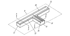
図1〜図3において、本発明の一実施の形態におけるケース未装着の複合センサは、角速度センサと加速度センサを有する複合センサであって、基板実装用の2つの支軸部2を有する固定基部4と、この2つの支軸部2の間に連結するとともに、外周縁から2つの支軸部2の間に向かって溝6を設けた2つの錘部8と、一方の錘部8に一端を連結するとともに、他方の錘部8に他端を連結した2つの第1振動素子10と、錘部8に設けた溝6の底部に一端を連結した2つの第2振動素子12と、信号処理回路が搭載され固定基部4の2つの支軸部2を取り付け支持した基板14とを備えている。そして、第1振動素子10および前記第2振動素子12を互いに駆動振動させ、錘部8の可動に起因して変化する第1振動素子10の駆動振動を検知して加速度を検出するとともに、コリオリ力に起因して変化する第2振動素子12の屈曲振動を検知して角速度を検出している。   1 to 3, the composite sensor without a case in one embodiment of the present invention is a composite sensor having an angular velocity sensor and an acceleration sensor, and a fixed base having two support shaft portions 2 for mounting on a substrate. 4 and two spindle parts 2 connected between the two spindle parts 2 and provided with a groove 6 between the two peripheral spindle parts 2 from the outer peripheral edge, and one spindle part 8 with one end , Two first vibration elements 10 having the other end connected to the other weight 8, two second vibration elements 12 having one end connected to the bottom of the groove 6 provided in the weight 8, and a signal And a substrate 14 on which a processing circuit is mounted and on which two support shafts 2 of the fixed base 4 are attached and supported. Then, the first vibration element 10 and the second vibration element 12 are driven to vibrate with each other, the driving vibration of the first vibration element 10 that changes due to the movement of the weight portion 8 is detected to detect acceleration, and Coriolis is detected. The angular velocity is detected by detecting the bending vibration of the second vibrating element 12 that changes due to the force.

この第1振動素子10は3つの線条体16を併設したスリット形状とし、第2振動素子12は互いに略直交させ連結した第1アーム18と第2アーム20とを有するT形状としており、2つの錘部8、2つの第1振動素子10、2つの第2振動素子12は、互いに固定基部4に対して対向配置するとともに、2つの第1振動素子10、2つの第2振動素子12は、2つの第1振動素子10と固定基部4とを結ぶ直線と、2つの第2振動素子12と固定基部4とを結ぶ直線とが略直交になるように配置している。このような配置により、互いに略直交したX軸とY軸とZ軸において、2つの第1振動素子10をX軸上に配置するとともに2つの第2振動素子12をY軸上に配置すると、2つの錘部8はX軸に対して線対称に配置される。   The first vibration element 10 has a slit shape in which three filaments 16 are provided side by side, and the second vibration element 12 has a T shape having a first arm 18 and a second arm 20 that are connected substantially orthogonal to each other. The two weight portions 8, the two first vibration elements 10, and the two second vibration elements 12 are arranged to face each other with respect to the fixed base 4, and the two first vibration elements 10 and the two second vibration elements 12 are The straight line connecting the two first vibration elements 10 and the fixed base 4 and the straight line connecting the two second vibration elements 12 and the fixed base 4 are arranged so as to be substantially orthogonal. With such an arrangement, when the two first vibrating elements 10 are arranged on the X axis and the two second vibrating elements 12 are arranged on the Y axis in the X axis, the Y axis, and the Z axis substantially orthogonal to each other, The two weight portions 8 are arranged symmetrically with respect to the X axis.

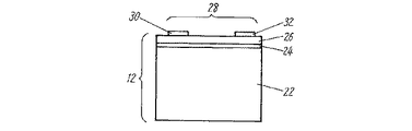
第1振動素子10において、3つの線条体16の2つには、駆動振動を与えるための駆動電極を配置し、残りの1つには駆動振動を検知する検出電極を配置し、共に、シリコン板22の上にPtの下部電極24を高周波スパッタにて形成し、この下部電極24の上部に高周波スパッタにてPZT圧電体26を形成し、さらに、上部にAu蒸着で上部電極28を形成している。この駆動電極に対して、下部電極24と上部電極28にシリコンが共振する共振周波数の交流電圧を印加すると、PZT圧電体26の伸縮が生じ、2つの線条体16が駆動振動する。線条体16が駆動振動する際は、3つの線条体16が互いに影響し合うので、検出電極を配置した線条体16から駆動振動を検知する。   In the first vibrating element 10, two of the three filaments 16 are provided with drive electrodes for applying drive vibration, and the remaining one is provided with a detection electrode for detecting drive vibration. A Pt lower electrode 24 is formed on the silicon plate 22 by high frequency sputtering, a PZT piezoelectric body 26 is formed on the lower electrode 24 by high frequency sputtering, and an upper electrode 28 is formed on the upper portion by Au evaporation. is doing. When an AC voltage having a resonance frequency at which silicon resonates is applied to the lower electrode 24 and the upper electrode 28, the PZT piezoelectric body 26 expands and contracts, and the two filaments 16 drive and vibrate. When the linear member 16 vibrates, the three linear members 16 influence each other, so that the driving vibration is detected from the linear member 16 on which the detection electrodes are arranged.

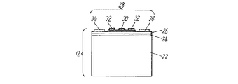
また、図4〜図6において、第2振動素子12には,第1振動素子10と同様に、駆動振動を与えるための駆動電極を配置し、さらに、角速度に起因する屈曲振動を検出するための検出電極を配置している。第1アーム18には、駆動負電極30を2つの駆動正電極32で挟むように、駆動正電極32および駆動負電極30を配置するとともに、これら、駆動正電極32と駆動負電極30を挟むように、検出正電極34と検出負電極36を配置している。第2アーム20には、第1アーム18に配置した駆動負電極30をT形状に配置し、駆動正電極32をL形状に配置している。2つの駆動正電極32の内、一方の駆動正電極32は駆動振動をモニタするモニタ正電極とし、駆動負電極30をモニタ負電極として共用してもよい。   4 to 6, similarly to the first vibration element 10, the second vibration element 12 is provided with a drive electrode for applying drive vibration, and further detects bending vibration caused by angular velocity. The detection electrodes are arranged. The first arm 18 is provided with the drive positive electrode 32 and the drive negative electrode 30 so that the drive negative electrode 30 is sandwiched between the two drive positive electrodes 32, and the drive positive electrode 32 and the drive negative electrode 30 are sandwiched therebetween. Thus, the detection positive electrode 34 and the detection negative electrode 36 are arranged. On the second arm 20, the driving negative electrode 30 arranged on the first arm 18 is arranged in a T shape, and the driving positive electrode 32 is arranged in an L shape. Of the two drive positive electrodes 32, one drive positive electrode 32 may be used as a monitor positive electrode for monitoring drive vibration, and the drive negative electrode 30 may be shared as a monitor negative electrode.

この第2振動素子12は、シリコン板22の上にPtの下部電極24を高周波スパッタにて形成し、この下部電極24の上部に高周波スパッタにてPZT圧電体26を形成し、さらに、上部にAu蒸着で上部電極28を形成している。上部電極28は駆動正電極32と駆動負電極30からなり、シリコンが共振する共振周波数の交流電圧を印加すると、駆動正電極32側と駆動負電極30側の各々において、PZT圧電体26の伸縮が生じ、第2アーム20が駆動振動する。   In the second vibrating element 12, a Pt lower electrode 24 is formed on a silicon plate 22 by high frequency sputtering, a PZT piezoelectric body 26 is formed on the lower electrode 24 by high frequency sputtering, and further on the upper portion. The upper electrode 28 is formed by Au deposition. The upper electrode 28 is composed of a drive positive electrode 32 and a drive negative electrode 30, and when an AC voltage having a resonance frequency at which silicon resonates is applied, the PZT piezoelectric body 26 expands and contracts on each of the drive positive electrode 32 side and the drive negative electrode 30 side. Occurs, and the second arm 20 vibrates.

次に、第1振動素子10の駆動振動と加速度が生じた場合の動作について説明する。   Next, an operation when drive vibration and acceleration of the first vibration element 10 occur will be described.

図7に示すように、第1振動素子10を矢印方向に互いに駆動振動させる。第1振動素子10は、3つの線条体16の内、隣接する線条体16の駆動方向を互いに逆方向にしており、線条体16をZ軸の(+Z)方向と(−Z)方向とに交互に繰り返すように駆動振動させる。この駆動振動をさせた状態で、錘部8の可動に起因して変化する第1振動素子10の駆動振動を検知して加速度を検出する。   As shown in FIG. 7, the first vibrating elements 10 are driven to vibrate in the direction of the arrows. In the first vibrating element 10, among the three linear bodies 16, the driving directions of the adjacent linear bodies 16 are opposite to each other, and the linear bodies 16 are moved in the Z axis (+ Z) direction and (−Z). Drive and vibrate to alternate with direction. In the state where this drive vibration is applied, the drive vibration of the first vibration element 10 that changes due to the movement of the weight portion 8 is detected to detect the acceleration.

例えば、図1、図7に示すように、X軸の(−X)方向側へ加速度が生じる(2つの錘部8がX軸の(+X)方向へ可動しようとする)と、(+X)方向側の第1振動素子10には矢印方向(A)に圧縮応力が生じる。このとき、(−X)方向側の第1振動素子10には、逆に引張応力が生じる。   For example, as shown in FIGS. 1 and 7, when acceleration occurs in the (−X) direction side of the X axis (the two weight portions 8 try to move in the (+ X) direction of the X axis), (+ X) A compressive stress is generated in the direction of the first vibration element 10 on the direction side in the arrow direction (A). At this time, a tensile stress is generated in the first vibration element 10 on the (−X) direction side.

また、X軸の(+X)方向側へ加速度が生じる(2つの錘部8がX軸の(−X)方向へ可動しようとする)と、(+X)方向側の第1振動素子10には矢印方向(B)に引張応力が生じる。このとき、(−X)方向側の第1振動素子10には、逆に圧縮応力が生じる。   Further, when acceleration occurs in the (+ X) direction side of the X axis (the two weight portions 8 try to move in the (−X) direction of the X axis), the first vibration element 10 on the (+ X) direction side has A tensile stress is generated in the arrow direction (B). At this time, a compressive stress is generated in the first vibration element 10 on the (−X) direction side.

2つの第1振動素子10には、錘部8の可動に応じて互いに異なる張力が加わり、2つの第1振動素子10の固有共振周波数が、錘部8の可動前の状態と比較すると変化する(一方の第1振動素子10の駆動振動波の周波数が高くなり、他方の第1振動素子10の駆動振動波の周波数が低くなる)ので、この固有共振周波数の差を検知すれば加速度を検出することができる。   Different tensions are applied to the two first vibration elements 10 according to the movement of the weight 8, and the natural resonance frequencies of the two first vibration elements 10 change as compared with the state before the movement of the weight 8. (The frequency of the drive vibration wave of one first vibration element 10 is increased, and the frequency of the drive vibration wave of the other first vibration element 10 is decreased), so that the acceleration can be detected by detecting the difference between the natural resonance frequencies. can do.

また、2つの第1振動素子10の駆動振動波の位相が、錘部8の可動前の状態と比較すると変化する(−方の第1振動素子10の駆動振動波の位相が進み、他方の第1振動素子10の駆動振動波の位相が遅れる)ので、この駆動振動波の差を検知しても加速度を検出することができる。   In addition, the phase of the drive vibration wave of the two first vibration elements 10 changes as compared with the state before the weight 8 is movable (the phase of the drive vibration wave of the negative first vibration element 10 advances, the other Since the phase of the driving vibration wave of the first vibration element 10 is delayed), the acceleration can be detected even if the difference between the driving vibration waves is detected.

上記の加速度を検出する際、例えば、図8に示すような加速度検出回路を用い、2つの第1振動素子10の駆動振動波に基づく各々の駆動信号を同期検波して検出する。この加速度検出回路の第1振動素子10には、抵抗38、増幅器40、バンドパスフィルタ42、AGC回路44、同期検波回路46、ローパスフィルタ48とを接続しており、第1振動素子10の共振周波数の変化に起因する位相差を検出して加速度を検出する。このとき、図9に示すように、錘部8の可動前における駆動信号の駆動信号波を駆動信号波Aとすると、錘部8の可動後における駆動信号の駆動信号波は、一方の第1振動素子10に対応するものは位相が遅れて駆動信号波Bとなり、他方の第1振動素子10に対応するものは位相が進んで駆動信号波Cとなる。   When detecting the acceleration, for example, an acceleration detection circuit as shown in FIG. 8 is used to detect and detect the respective drive signals based on the drive vibration waves of the two first vibration elements 10 by synchronous detection. A resistor 38, an amplifier 40, a band pass filter 42, an AGC circuit 44, a synchronous detection circuit 46, and a low pass filter 48 are connected to the first vibration element 10 of the acceleration detection circuit. An acceleration is detected by detecting a phase difference caused by a change in frequency. At this time, as shown in FIG. 9, if the drive signal wave of the drive signal before the weight portion 8 is moved is the drive signal wave A, the drive signal wave of the drive signal after the weight portion 8 is moved is one of the first signal waves. The phase corresponding to the vibration element 10 becomes the drive signal wave B with a phase delay, and the phase corresponding to the other first vibration element 10 becomes the drive signal wave C with the phase advanced.

次に、第2振動素子12の駆動振動と角速度が生じた場合の動作について説明する。   Next, the operation when the drive vibration and the angular velocity of the second vibration element 12 occur will be described.

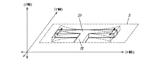
図10に示すように、第2振動素子12は、第2アーム20の両端を互いにY軸の(+Y)方向と(−Y)方向とに交互に繰り返すように駆動振動させる。この駆動振動をさせた状態で、コリオリ力に起因して変化する第2振動素子12の屈曲振動を検知して角速度を検出する。第2振動素子12に屈曲振動が生じると、シリコン板22に形成したPZT圧電体26が歪み、検出正電極34と検出負電極36に電荷が発生するのでこれを検知する。   As shown in FIG. 10, the second vibrating element 12 vibrates and drives the both ends of the second arm 20 to alternately repeat in the (+ Y) direction and the (−Y) direction of the Y axis. In the state where this driving vibration is applied, the angular vibration is detected by detecting the bending vibration of the second vibration element 12 that changes due to the Coriolis force. When bending vibration is generated in the second vibration element 12, the PZT piezoelectric body 26 formed on the silicon plate 22 is distorted, and charges are generated in the detection positive electrode 34 and the detection negative electrode 36, which are detected.

例えば、図11に示すように、X軸周りに角速度が生じると、Z軸方向への第1アーム18の屈曲振動を検知して角速度を検出する。第2アーム20は全体がZ軸の(+Z)方向と(−Z)方向とに交互に繰り返すように屈曲振動するので、第1アーム18もそれに伴いZ軸の(+Z)方向と(−Z)方向とに交互に繰り返すように屈曲振動する。   For example, as shown in FIG. 11, when an angular velocity is generated around the X axis, the angular velocity is detected by detecting the bending vibration of the first arm 18 in the Z axis direction. Since the second arm 20 bends and vibrates so that the entirety repeats alternately in the (+ Z) direction and the (−Z) direction of the Z axis, the first arm 18 also follows the (+ Z) direction of the Z axis (−Z). ) Bend and vibrate to repeat alternately in the direction.

例えば、図12に示すように、Z軸周りに角速度が生じると、X軸方向への第1アーム18の屈曲振動を検知して角速度を検出する。第2アーム20は全体がX軸の(+X)方向と(−X)方向とに交互に繰り返すように屈曲振動するので、第1アーム18もそれに伴いX軸の(+X)方向と(−X)方向とに交互に繰り返すように屈曲振動する。   For example, as shown in FIG. 12, when an angular velocity occurs around the Z-axis, the angular velocity is detected by detecting the bending vibration of the first arm 18 in the X-axis direction. Since the second arm 20 bends and vibrates so that the entirety repeats alternately in the (+ X) direction and the (−X) direction of the X axis, the first arm 18 also follows the (+ X) direction and the (−X) direction of the X axis. ) Bend and vibrate to repeat alternately in the direction.

上記の角速度を検出する際、例えば、図13に示すような角速度検出回路を用い、2つの第2振動素子12の屈曲振動波に基づく各々の屈曲信号を同期検波して検出する。この角速度検出回路の第2振動素子12には、抵抗38、増幅器40、バンドパスフィルタ42、AGC回路44、同期検波回路46、ローパスフィルタ48とを接続しており、第2振動素子12の固有共振周波数の差、または、駆動振動波の位相差を検出して角速度を検出する。   When the angular velocity is detected, for example, an angular velocity detection circuit as shown in FIG. 13 is used to detect and detect the respective bending signals based on the bending vibration waves of the two second vibrating elements 12. A resistor 38, an amplifier 40, a band pass filter 42, an AGC circuit 44, a synchronous detection circuit 46, and a low pass filter 48 are connected to the second vibration element 12 of this angular velocity detection circuit. The angular velocity is detected by detecting the difference in resonance frequency or the phase difference of the driving vibration wave.

上記構成により、固定基部4に連結した2つの錘部8と、一方の錘部8に一端を連結するとともに、他方の錘部8に他端を連結した第1振動素子10と、錘部8に一端を連結した第2振動素子12とを設け、これら第1振動素子10および第2振動素子12を互いに駆動振動させるので、加速度センサとしては、錘部8の可動に起因して変化する第1振動素子10の駆動振動を検知して加速度を検出することができ、角速度センサとしては、第2振動素子12の屈曲振動を検知して角速度を検出することができる。すなわち、角速度センサと加速度センサとを複合でき、実装面積を低減して実装基板14の小型化を図ることができる。   With the above configuration, the two weight portions 8 connected to the fixed base portion 4, the first vibration element 10 having one end connected to one weight portion 8 and the other end connected to the other weight portion 8, and the weight portion 8. The first vibration element 10 and the second vibration element 12 are driven and vibrated with each other, so that the acceleration sensor is a first variable that changes due to the movement of the weight portion 8. The acceleration can be detected by detecting the driving vibration of the first vibration element 10, and the angular velocity can be detected by detecting the bending vibration of the second vibration element 12 as the angular velocity sensor. That is, the angular velocity sensor and the acceleration sensor can be combined, and the mounting area can be reduced and the mounting substrate 14 can be downsized.

加速度の検出に当っては、第1振動素子10の駆動振動における固有共振周波数の差、
または、2つの第1振動素子10の駆動振動における駆動振動波の位相差を検知すれば、容易に精度良く検出できる。このとき、第1振動子は複数の線条体16を併設したスリット形状とし、隣接する線条体16を互いに逆方向に駆動振動させれば、感度が増幅して非常に精度良く検出できる。特に、外周縁から固定基部4に向かって溝6を有し、この溝6の底部に第2振動素子12を連結すれば、第2振動素子12の駆動振動と屈曲振動に影響を与えることなく、第1振動素子10の感度をさらに増幅することができる。
In detecting the acceleration, the difference in natural resonance frequency in the drive vibration of the first vibration element 10,
Or if the phase difference of the drive vibration wave in the drive vibration of the two 1st vibration elements 10 is detected, it can detect easily and accurately. At this time, if the first vibrator has a slit shape in which a plurality of linear bodies 16 are provided side by side, and the adjacent linear bodies 16 are driven to vibrate in opposite directions, sensitivity is amplified and detection can be performed with very high accuracy. In particular, if the groove 6 is provided from the outer peripheral edge toward the fixed base 4 and the second vibration element 12 is connected to the bottom of the groove 6, the driving vibration and bending vibration of the second vibration element 12 are not affected. The sensitivity of the first vibration element 10 can be further amplified.

角速度の検出に当っては、第2振動子は互いに略直交させ連結した第1アーム18と第2アーム20とを有するT形状とし、第1アーム18を錘部8に連結し、第2アーム20を駆動振動させることにより、2軸方向の角速度を検出できるとともに低背化できる。   In detecting the angular velocity, the second vibrator has a T shape having a first arm 18 and a second arm 20 which are connected substantially orthogonally to each other, the first arm 18 is connected to the weight portion 8, and the second arm is connected. By driving and vibrating 20, the angular velocity in the biaxial direction can be detected and the height can be reduced.

また、2つの第1振動素子10を固定基部4に対して対向配置し、2つの第1振動素子10と固定基部4とを一直線上に配置しているので、第1振動素子10の駆動に起因したノイズを抑制するとともに、2つの第2振動素子12を固定基部4に対して対向配置し、2つの第2振動素子12と固定基部4とを一直線上に配置しているので、第2振動素子12の駆動に起因したノイズを抑制し、加速度と角速度をより精度良く検出できる。特に、2つの第1振動素子10と固定基部4とを結ぶ直線と、2つの第2振動素子12と固定基部4とを結ぶ直線とを略直交させているので、対称形状となり、第1振動素子10および第2振動素子12の駆動に起因したノイズをより抑制できる。   Further, since the two first vibration elements 10 are arranged opposite to the fixed base 4 and the two first vibration elements 10 and the fixed base 4 are arranged on a straight line, the first vibration element 10 is driven. In addition to suppressing the noise caused, the two second vibration elements 12 are arranged opposite to the fixed base 4 and the two second vibration elements 12 and the fixed base 4 are arranged in a straight line. Noise caused by driving the vibration element 12 can be suppressed, and acceleration and angular velocity can be detected with higher accuracy. In particular, since the straight line connecting the two first vibration elements 10 and the fixed base 4 and the straight line connecting the two second vibration elements 12 and the fixed base 4 are substantially orthogonal to each other, the shape becomes symmetrical and the first vibration Noise due to driving of the element 10 and the second vibration element 12 can be further suppressed.

さらに、固定基部4は、基板14実装用の2つの支軸部2を有し、この支軸部2の間に錘部8を連結すれば、基板14に固定基部4を的確に実装できるとともに、錘部8の可動に起因したノイズを抑制できる。   Further, the fixed base 4 has two support shaft portions 2 for mounting the substrate 14, and if the weight portion 8 is connected between the support shaft portions 2, the fixed base 4 can be accurately mounted on the substrate 14. The noise resulting from the movement of the weight 8 can be suppressed.

以上のように、本発明にかかる複合センサは、航空機、自動車、ロボット、船舶、車両等の移動体の姿勢制御やナビゲーション等、各種電子機器に用いることができる。   As described above, the composite sensor according to the present invention can be used for various electronic devices such as attitude control and navigation of moving bodies such as aircraft, automobiles, robots, ships, and vehicles.

本発明の一実施の形態におけるケース未装着の複合センサの斜視図1 is a perspective view of a composite sensor without a case in one embodiment of the present invention. 図1のA部の拡大斜視図Enlarged perspective view of part A in FIG. 図2のA−A断面図AA sectional view of FIG. 図1のB部の拡大斜視図Enlarged perspective view of part B in FIG. 図4のA−A断面図AA sectional view of FIG. 図4のB−B断面図BB sectional view of FIG. 図1のA部の駆動状態と動作状態を示す斜視図The perspective view which shows the drive state and operation | movement state of the A section of FIG. 加速度検出回路図Acceleration detection circuit diagram 駆動信号の波形図Drive signal waveform diagram 図1のB部の駆動状態を示す斜視図The perspective view which shows the drive state of the B section of FIG. 図1のB部の動作状態を示す斜視図The perspective view which shows the operation state of the B section of FIG. 図1のB部の駆動状態を示す斜視図The perspective view which shows the drive state of the B section of FIG. 角速度検出回路図Angular velocity detection circuit diagram

符号の説明Explanation of symbols

2 支軸部
4 固定基部
6 溝
8 錘部
10 第1振動素子
12 第2振動素子
14 基板
16 線条体
18 第1アーム
20 第2アーム
22 シリコン板
24 下部電極
26 PZT圧電体
28 上部電極
30 駆動負電極
32 駆動正電極
34 検出正電極
36 検出負電極
38 抵抗
40 増幅器
42 バンドパスフィルタ
44 AGC回路
46 同期検波回路
48 ローパスフィルタ
2 Supporting shaft portion 4 Fixed base portion 6 Groove 8 Weight portion 10 First vibration element 12 Second vibration element 14 Substrate 16 Linear body 18 First arm 20 Second arm 22 Silicon plate 24 Lower electrode 26 PZT piezoelectric body 28 Upper electrode 30 Drive negative electrode 32 Drive positive electrode 34 Detection positive electrode 36 Detection negative electrode 38 Resistance 40 Amplifier 42 Band pass filter 44 AGC circuit 46 Synchronous detection circuit 48 Low pass filter

Claims (10)

角速度センサと加速度センサを有する複合センサであって、固定基部に連結した2つの錘部と、一方の前記錘部に一端を連結するとともに、他方の前記錘部に他端を連結した第1振動素子と、前記錘部に一端を連結した第2振動素子とを設け、前記第1振動素子および前記第2振動素子を互いに駆動振動させ、前記錘部の可動に起因して変化する前記第1振動素子の駆動振動を検知して加速度を検出するとともに、コリオリ力に起因して変化する前記第2振動素子の屈曲振動を検知して角速度を検出する複合センサ。 A combined sensor having an angular velocity sensor and an acceleration sensor, the first vibration having two weight parts connected to a fixed base and one end connected to one of the weight parts and the other end connected to the other weight part. An element and a second vibration element having one end connected to the weight portion are provided, the first vibration element and the second vibration element are driven to vibrate with each other, and the first change is caused by the movement of the weight portion. A composite sensor that detects an acceleration by detecting a driving vibration of a vibration element and detects an angular velocity by detecting a bending vibration of the second vibration element that changes due to a Coriolis force. 2つの前記第1振動素子を前記固定基部に対して対向配置し、2つの前記第1振動素子と前記固定基部とを一直線上に配置した請求項1記載の複合センサ。 2. The composite sensor according to claim 1, wherein the two first vibration elements are arranged opposite to the fixed base, and the two first vibration elements and the fixed base are arranged on a straight line. 2つの前記第1振動素子の駆動振動における固有共振周波数の差を検知して加速度を検出する請求項2記載の複合センサ。 The composite sensor according to claim 2, wherein acceleration is detected by detecting a difference between natural resonance frequencies in driving vibration of the two first vibration elements. 2つの前記第1振動素子の駆動振動における駆動振動波の位相差を検知して加速度を検出する請求項2記載の複合センサ。 The composite sensor according to claim 2, wherein an acceleration is detected by detecting a phase difference between driving vibration waves in driving vibration of the two first vibration elements. 2つの前記第2振動素子を前記固定基部に対して対向配置し、2つの前記第2振動素子と前記固定基部とを一直線上に配置した請求項1記載の複合センサ。 2. The composite sensor according to claim 1, wherein the two second vibration elements are disposed to face the fixed base, and the two second vibration elements and the fixed base are disposed on a straight line. 2つの前記第1振動素子を前記固定基部に対して対向配置するとともに、2つの前記第2振動素子を前記固定基部に対して対向配置し、2つの前記第1振動素子と前記固定基部とを結ぶ直線と、2つの前記第2振動素子と前記固定基部とを結ぶ直線とを略直交させた請求項1記載の複合センサ。 The two first vibration elements are disposed opposite to the fixed base, the two second vibration elements are disposed opposite to the fixed base, and the two first vibration elements and the fixed base are disposed. The composite sensor according to claim 1, wherein a straight line connecting and a straight line connecting two second vibration elements and the fixed base are substantially orthogonal. 前記錘部は外周縁から前記固定基部に向かって溝を有し、前記溝の底部に前記第2振動素子を連結した請求項1記載の複合センサ。 The composite sensor according to claim 1, wherein the weight portion has a groove from an outer peripheral edge toward the fixed base, and the second vibration element is connected to a bottom portion of the groove. 前記第1振動素子は複数の線条体を併設したスリット形状であって、隣接する前記線条体を互いに逆方向に駆動振動させた請求項1記載の複合センサ。 2. The composite sensor according to claim 1, wherein the first vibrating element has a slit shape in which a plurality of linear bodies are provided side by side, and the adjacent linear bodies are driven and vibrated in directions opposite to each other. 第2振動素子は互いに略直交させ連結した第1アームと第2アームとを有するT形状であって、前記第1アームを前記錘部に連結し、前記第2アームを駆動振動させた請求項1記載の複合センサ。 The second vibration element has a T shape having a first arm and a second arm that are connected substantially orthogonally to each other, wherein the first arm is connected to the weight portion, and the second arm is driven to vibrate. The composite sensor according to 1. 前記固定基部は、基板実装用の2つの支軸部を有し、前記支軸部の間に前記錘部を連結した請求項1記載の複合センサ。 The composite sensor according to claim 1, wherein the fixed base portion has two support shaft portions for board mounting, and the weight portion is connected between the support shaft portions.
JP2005040145A 2005-02-17 2005-02-17 Compound sensor Pending JP2006226802A (en)

Priority Applications (1)

Application Number Priority Date Filing Date Title
JP2005040145A JP2006226802A (en) 2005-02-17 2005-02-17 Compound sensor

Applications Claiming Priority (1)

Application Number Priority Date Filing Date Title
JP2005040145A JP2006226802A (en) 2005-02-17 2005-02-17 Compound sensor

Publications (1)

Publication Number Publication Date
JP2006226802A true JP2006226802A (en) 2006-08-31

Family

ID=36988315

Family Applications (1)

Application Number Title Priority Date Filing Date
JP2005040145A Pending JP2006226802A (en) 2005-02-17 2005-02-17 Compound sensor

Country Status (1)

Country Link
JP (1) JP2006226802A (en)

Cited By (3)

* Cited by examiner, † Cited by third party
Publication number Priority date Publication date Assignee Title
JP2008070230A (en) * 2006-09-14 2008-03-27 Hitachi Ltd Physical quantity sensor
JP2008175578A (en) * 2007-01-16 2008-07-31 Nec Tokin Corp Vibrator for piezoelectric vibrating gyroscope
JP2016530612A (en) * 2013-07-17 2016-09-29 シュタビロ インターナツィオナール ゲーエムベーハーSTABILO International GmbH Electronic pen

Cited By (4)

* Cited by examiner, † Cited by third party
Publication number Priority date Publication date Assignee Title
JP2008070230A (en) * 2006-09-14 2008-03-27 Hitachi Ltd Physical quantity sensor
JP2008175578A (en) * 2007-01-16 2008-07-31 Nec Tokin Corp Vibrator for piezoelectric vibrating gyroscope
JP2016530612A (en) * 2013-07-17 2016-09-29 シュタビロ インターナツィオナール ゲーエムベーハーSTABILO International GmbH Electronic pen
US10474252B2 (en) 2013-07-17 2019-11-12 Stabilo International Gmbh Electronic pen

Similar Documents

Publication Publication Date Title
JP5205725B2 (en) Angular velocity sensor
JP5206409B2 (en) Angular velocity sensor
JP5205970B2 (en) Inertial force sensor
JP4929918B2 (en) Compound sensor
JP2007256235A (en) Inertia force sensor
JP2008076265A (en) Inertial force sensor
JP2012149961A (en) Vibration gyro
JP2006226802A (en) Compound sensor
JPWO2010092806A1 (en) Inertial force sensor and detection element used therefor
JP4687085B2 (en) Compound sensor
JP2006162314A (en) Compound sensor
JP4774733B2 (en) Compound sensor
JP2008122263A (en) Angular velocity sensor
JP2008190972A (en) Angular velocity sensor
JP2007256234A (en) Inertia force sensor
JP5125138B2 (en) Compound sensor
JP4858215B2 (en) Compound sensor
JP2010230346A (en) Angular velocity sensor
JP2008046056A (en) Angular velocity sensor
JP2007198778A (en) Inertial force sensor
JP2008122262A (en) Angular velocity sensor
JP2007198779A (en) Inertial force sensor
JP2008190887A (en) Sensor
JP2006105756A (en) Angular velocity sensor
JP2007198776A (en) Inertia force sensor