EP2062868B1 - Process for purifying diaryl carbonates - Google Patents
Process for purifying diaryl carbonates Download PDFInfo
- Publication number
- EP2062868B1 EP2062868B1 EP08019730.4A EP08019730A EP2062868B1 EP 2062868 B1 EP2062868 B1 EP 2062868B1 EP 08019730 A EP08019730 A EP 08019730A EP 2062868 B1 EP2062868 B1 EP 2062868B1
- Authority
- EP
- European Patent Office
- Prior art keywords
- column
- distillation column
- carbonate
- diaryl carbonate
- process according
- Prior art date
- Legal status (The legal status is an assumption and is not a legal conclusion. Google has not performed a legal analysis and makes no representation as to the accuracy of the status listed.)
- Not-in-force
Links
Images


Classifications
-
- C—CHEMISTRY; METALLURGY
- C07—ORGANIC CHEMISTRY
- C07C—ACYCLIC OR CARBOCYCLIC COMPOUNDS
- C07C68/00—Preparation of esters of carbonic or haloformic acids
- C07C68/08—Purification; Separation; Stabilisation
-
- B—PERFORMING OPERATIONS; TRANSPORTING
- B01—PHYSICAL OR CHEMICAL PROCESSES OR APPARATUS IN GENERAL
- B01D—SEPARATION
- B01D3/00—Distillation or related exchange processes in which liquids are contacted with gaseous media, e.g. stripping
- B01D3/14—Fractional distillation or use of a fractionation or rectification column
- B01D3/141—Fractional distillation or use of a fractionation or rectification column where at least one distillation column contains at least one dividing wall
-
- Y—GENERAL TAGGING OF NEW TECHNOLOGICAL DEVELOPMENTS; GENERAL TAGGING OF CROSS-SECTIONAL TECHNOLOGIES SPANNING OVER SEVERAL SECTIONS OF THE IPC; TECHNICAL SUBJECTS COVERED BY FORMER USPC CROSS-REFERENCE ART COLLECTIONS [XRACs] AND DIGESTS
- Y02—TECHNOLOGIES OR APPLICATIONS FOR MITIGATION OR ADAPTATION AGAINST CLIMATE CHANGE
- Y02P—CLIMATE CHANGE MITIGATION TECHNOLOGIES IN THE PRODUCTION OR PROCESSING OF GOODS
- Y02P20/00—Technologies relating to chemical industry
- Y02P20/50—Improvements relating to the production of bulk chemicals
Definitions
- the present invention is a special process for the purification of diaryl carbonates.
- diaryl carbonate is due to the high demands on their purity for the production of high quality polycarbonates by melt transesterification of great importance.
- Diaryl carbonates prepared from transesterification of an aromatic hydroxy compound with an alkyl carbonate can contain both high-boiling and medium-boiling secondary components and catalyst residues as impurities.
- High-boiling components - often referred to as high boilers - in the sense of this preparation are those whose boiling point above that of the diaryl carbonate.
- Medium-boiling components-often also referred to as intermediates-in the context of this preparation process are those whose boiling point lies between that of the diaryl carbonate and that of the alkylaryl carbonate formed as a by-product during the preparation of the diaryl carbonate. All of these impurities lead to considerable deterioration of the quality of the polycarbonates to be produced and must be removed by further purification before further processing of the diaryl carbonates.
- a process for recovering a product stream from a waste stream in the production of diaryl carbonate is described.
- a workup of the diaryl carbonate, which was prepared in a reaction consisting of three reaction columns, is also described, which is carried out in three stages consisting of catalyst removal, low boiler and high boiler removal. Both in the first and in the last-mentioned step, the diaryl carbonate is separated off as top product.
- the process described is not only extremely expensive in terms of apparatus, but also because of the separation of the diaryl carbonate both in the first and in the third stage as a top product energetically unfavorable.
- the quality of the diaryl carbonate produced in this way is very poor at 99.5% by weight and unsuitable for the production of high-quality polycarbonate.
- EP 1 783 112 A1 EP 1 787 977 A1 .
- EP 1 801 095 A1 and EP 1 787 976 A1 describes a process consisting of at least two stages for the purification of diaryl carbonate, in particular diphenyl carbonate, in which, after the reaction, first the high-boiling components and the catalyst are separated off. The resulting in this high boiler separation distillate is separated into three fractions in a second distillation column, taking diaryl carbonate in the side stream.
- a disadvantage of this method is that the separation of the high-boiling components in the first step, since this is energetically unfavorable.
- the object underlying the present invention was to provide such a method.
- Diaryl carbonates to be purified in the context of the invention are preferably those of the general one where R, R 'and R "independently of one another are H, linear or branched, optionally substituted C 1 -C 34 -alkyl, preferably C 1 -C 6 -alkyl, particularly preferably C 1 -C 4 -alkyl, C 1 -C 34 Alkoxy, preferably C 1 -C 6 -alkoxy, more preferably C 1 -C 4 -alkoxy, C 5 -C 34 -cycloalkyl, C 7 -C 34 -alkylaryl, C 6 -C 34 -aryl or a halogen radical represent a chlorine radical and R, R 'and R "may be the same or different on both sides of the formula (I).
- R can also be -COO-R "', where R'" H, optionally branched C 1 -C 34 alkyl, preferably C 1 -C 6 alkyl, particularly preferably C 1 -C 4 alkyl, C 1 -C 34 Alkoxy, preferably C 1 -C 6 -alkoxy, particularly preferably C 1 -C 4 -alkoxy, C 5 -C 34 -cycloalkyl, C 7 -C 34 -alkylaryl or C 6 -C 34 -aryl.
- R, R' and R" are very particularly preferably H.
- Diarylcarbonates of the general formula (I) are, for example: diphenyl carbonate, methylphenylphenyl carbonates and di (methylphenyl) carbonates, also as a mixture, where the position of the methyl group on the phenyl rings may be arbitrary, and dimethylphenyl-phenyl-carbonates and di ( dimethylphenyl) carbonates, also as a mixture, wherein the position of the methyl groups on the phenyl rings may be arbitrary, chlorophenyl-phenyl-carbonates and di (chlorophenyl) carbonates, wherein the position of the methyl group on the phenyl rings may be arbitrary, 4-ethylphenyl phenyl carbonate, di- (4-ethylphenyl) carbonate, 4-n-propylphenyl phenyl carbonate, di- (4-n-propylphenyl) carbonate, 4-iso-propylphenyl-phenyl-carbonate, di- (4-iso
- Preferred diaryl carbonates are: diphenyl carbonate, 4-tert-butylphenyl phenyl carbonate, di (4-tert-butylphenyl) carbonate, biphenyl-4-yl phenyl carbonate, di (biphenyl-4-yl) carbonate, 4- (1-methyl-1-phenylethyl) -phenyl-phenyl-carbonate and di- [4- (1-methyl-1-phenylethyl) -phenyl] -carbonate.
- diphenyl carbonate is particularly preferred.
- Dialkyl carbonates in the context of the invention are those of the formula (II) wherein R 1 and R 2 independently of one another are linear or branched, optionally substituted C 1 -C 34 -alkyl, preferably C 1 -C 6 -alkyl, more preferably C 1 -C 4 -alkyl.
- R 1 and R 2 may be the same or different.
- R 1 and R 2 are the same.
- Preferred dialkyl carbonates are dimethyl carbonate, diethyl carbonate, di (n-propyl) carbonate, di (iso-propyl) carbonate, di (n-butyl) carbonate, di (sec-butyl) carbonate, di (tert-butyl) carbonate or dihexyl carbonate. Particularly preferred are dimethyl carbonate or diethyl carbonate. Very particular preference is given to dimethyl carbonate.
- Aromatic hydroxy compounds in the context of the invention are preferably those of the general formula (III) wherein R, R 'and R "independently of one another may have the meaning given for the general formula (I).
- aromatic hydroxy compounds are, for example: phenol, o-, m- or p-cresol, also as a mixture of cresols, dimethylphenol, also as a mixture, wherein the position of the methyl groups on the phenol ring may be arbitrary, e.g.
- Preferred aromatic hydroxy compounds are phenol, 4-tert-butylphenol, biphenyl-4-ol and 4- (1-methyl-1-phenylethyl) phenol.
- Particularly preferred is phenol.
- C 1 -C 4 -alkyl is, for example, methyl, ethyl, n-propyl, isopropyl, n-butyl, sec-butyl, tert-butyl, C 1 -C 6 -alkyl, moreover, for example, n -Pentyl, 1-methylbutyl, 2-methylbutyl, 3-methylbutyl, neo-pentyl, 1-ethylpropyl, n-hexyl, 1,1-dimethylpropyl, 1,2-dimethylpropyl, 1,2-dimethylpropyl, 1-methylpentyl, 2 -methylpentyl, 3-methylpentyl, 4-methylpentyl, 1,1-dimethylbutyl, 1,2-dimethylbutyl, 1,3-dimethylbutyl, 2,2-dimethylbutyl, 2,3-dimethylbutyl, 3,3-dimethylbutyl, 1-
- Alkylene radicals in the corresponding hydroxyalkyl or aralkyl or alkylaryl radicals are, for example, the alkylene radicals corresponding to the preceding alkyl radicals.
- Aryl represents a carbocyclic aromatic radical having 6 to 34 skeleton carbon atoms.
- aromatic part of an arylalkyl radical also called aralkyl radical
- aryl constituents of more complex groups such as e.g. Arylcarbonyl.
- Arylalkyl or aralkyl are each independently a straight, branched or unbranched alkyl radical as defined above which is simple, can be substituted by aryl radicals as defined above, multiply or fully.
- transesterification catalysts known from the literature for the dialkyl carbonate-phenol transesterification can be used.
- alkali and alkaline earth metals such as lithium, sodium, potassium, rubidium, cesium, magnesium and calcium, preferably lithium, sodium, potassium, magnesium and calcium, and particularly preferably lithium , Sodium and potassium (cf., eg US Pat. No. 3,642,858 . US 3,803,201 or EP-A 1082 ).
- Salts of the alkali and alkaline earth metals may also be those of organic or inorganic acids, such as acetic acid, propionic acid, butyric acid, benzoic acid, stearic acid, carbonic acid (carbonates or bicarbonates), phosphoric acid, hydrocyanic acid, hydroxydic acid, boric acid, stannic acid, C 14 -Stannonklaren or antimony acid.
- Preferred compounds of the alkali metals and alkaline earth metals are the oxides, hydroxides, alcoholates, acetates, propionates, benzoates, carbonates and bicarbonates, particularly preferably hydroxides, alcoholates, acetates, benzoates or carbonates.
- the alkali metal or alkaline earth metal compounds mentioned are preferably used in amounts of from 0.001 to 2% by weight, preferably from 0.005 to 0.9% by weight and more preferably from 0.01 to 0.5% by weight, based on the weight of the reaction mixture to be reacted.
- Further catalysts which can be used according to the invention are metal compounds such as AlX 3 , TiX 3 , UX 4 , TiX 4 , VOX 3 , VX 5 , ZnX 2 , FeX 3 , PbX 2 and SnX 4 , in which X represents halogen, acetoxy, alkoxy or aryloxy radicals stands ( DE-OS 2 58 412 ).
- metal compounds TiX 4 are metal compounds such as AlX 3 , TiX 4 , PbX 2 and SnX 4 , for example titanium tetrachloride, titanium tetramethoxide, titanium tetraoxide, titanium tetraethoxide, titanium tetraisopropylate, titanium tetradodecylate, tin tetraisooctylate and aluminum triisopropylate.
- metal compounds TiX 4 are TiX 4 .
- the stated metal compounds are preferably used in amounts of 0.001 to 5 wt .-%, preferably from 0.005 to 5 wt .-% and particularly preferably from 0.01 to 5 wt .-%, based on the weight of the reaction mixture to be reacted.
- Halogen means in the context of the invention fluorine, chlorine or bromine, preferably fluorine or chlorine, more preferably chlorine.
- organotin compounds which can be used according to the invention are organotin compounds of the general formula (R 11 ) 4-X- Sn (Y) X in which Y is a radical OCOR 12 , OH or OR, where R 12 is C 1 -C 12 -alkyl, C 6 -C 12 aryl or C 7 -C 13 -alkylaryl, R 11 independently of R 12 has the meaning of R 12 and x is an integer from 1 to 3, dialkyltin compounds having 1 to 12 carbon atoms in the alkyl radical or compounds bis (trialkyltin) such as trimethyltin acetate, triethyltin benzoate, tributyltin acetate, triphenyltin acetate, dibutyltin diacetate, dibutyltin dilaurate, dioctyltin dilaurate, Dibutylzinnadipinat, dibutyldimethoxytin, Dimethylzinngly
- tin compounds which can be used according to the invention are Sn (II) oxides of the general formula XR 2 Sn-OR 2 Sn-Y, in which X and Y are, independently of one another, OH, SCN, OR 13 , OCOR 13 or halogen and R is alkyl, aryl, in which R 13 has the meaning given above for R 12 ( EP 0 338 760 ).
- catalysts are lead compounds, optionally together with triorganophosphanes, a chelate compound or an alkali metal, for example Pb (OH) 2 -2PbCO 3, Pb (OCO-CH 3) 2, Pb (OCO-CH 3) 2 ⁇ 2LiCl, Pb (OCO-CH 3 ) 2 • 2PPh 3 in amounts of from 0.001 to 1, preferably from 0.005 to 0.25, moles per mole of dialkyl carbonate ( JP 57/176932 .
- a chelate compound or an alkali metal for example Pb (OH) 2 -2PbCO 3, Pb (OCO-CH 3) 2, Pb (OCO-CH 3) 2 ⁇ 2LiCl, Pb (OCO-CH 3 ) 2 • 2PPh 3 in amounts of from 0.001 to 1, preferably from 0.005 to 0.25, moles per mole of dialkyl carbonate ( JP 57/176932 .
- JP 01/093580 As well as other lead (II) and lead (IV) compounds, such as PbO, PbO 2 , Mennige, Plumbite, and Plumbate ( JP 01/093560 ), Iron (III) acetate ( JP 61/1 72 852 ), copper salts and / or metal complexes, for example of alkali, zinc, titanium and iron ( JP 89/005588 ).
- lead (II) and lead (IV) compounds such as PbO, PbO 2 , Mennige, Plumbite, and Plumbate ( JP 01/093560 ), Iron (III) acetate ( JP 61/1 72 852 ), copper salts and / or metal complexes, for example of alkali, zinc, titanium and iron ( JP 89/005588 ).
- Preferred catalysts for the process according to the invention are the abovementioned metal compounds AlX 3 , TiX 3 , UX 4 , TiX 4 , VOX 3 , VX 5 , ZnX 2 , FeX 3 , PbX 2 and SnX 4 .
- AlX 3 , TiX 4 , PbX 2 and SnX 4 examples of which include titanium tetrachloride, titanium tetramethoxide, titanium tetraphenoxide, titanium tetraethoxide, titanium tetraisopropylate, titanium tetradodecylate, tin tetraisooctylate and aluminum triisopropylate.
- metal compounds TiX 4 Particularly preferred are titanium tetramethoxide, titanium tetraphenoxide and titanium tetraethoxide.
- the diaryl carbonate to be purified contains compounds having a boiling point between that of the diaryl carbonate and that of the alkylaryl carbonate formed as an intermediate during the preparation of the diaryl carbonate as an impurity, which are removed in a further side stream of the first distillation column.
- This further side stream take-off takes place in the first distillation column, preferably above the side stream take-off for the diaryl carbonate.
- Alkylaryl carbonates formed as an intermediate during the preparation of the diaryl carbonate in the context of the invention are preferably those of the general formula (IV) wherein R, R 'and R "for the general formula (I) and R 1 may have the meaning given for the general formula (II).
- Preferred alkylaryl carbonates are methyl phenyl carbonate, ethyl phenyl carbonate, propyl phenyl carbonate, butyl phenyl carbonate and hexyl phenyl carbonate, methyl (o-cresyl) carbonate, methyl (p-cresyl) carbonate , Ethyl (o-cresyl) carbonate, ethyl (p-cresyl) carbonate, methyl or ethyl (p-chlorophenyl) carbonate.
- Especially preferred Alkylaryl carbonates are methyl phenyl carbonate and ethyl phenyl carbonate. Very particular preference is given to methylphenyl carbonate.
- the diaryl carbonate to be purified - also referred to as crude diaryl carbonate - contains 10 to 90 wt .-%, particularly preferably 20 to 80 wt .-% and most preferably 40 to 80 wt .-% diaryl and 5 to 90 wt .-%, especially preferably 5 to 60% by weight and very particularly preferably 5 to 40% by weight of alkylaryl carbonate, 1 to 90% by weight, particularly preferably 1 to 50% by weight and very particularly preferably 1 to 30% by weight of aromatic Hydroxy compound, 0 to 5 wt .-%, particularly preferably 0 to 2 wt .-% and most preferably 0 to 0.5 wt .-% high-boiling secondary components, 0 to 5 wt .-%, particularly preferably 0.0001 to 2 Wt .-% and very particularly preferably 0.0001 to 1 wt .-% medium-boiling secondary components and 0.01 to 10 wt .-%, particularly preferably
- High-boiling secondary components - often referred to as high boilers - are within the scope of the invention, those whose boiling point above that of the diaryl carbonate.
- diaryl carbonates having a purity of, i. E. a content of pure diaryl carbonate of from 99 to 100% by weight, particularly preferably from 99.5 to 100% by weight and very particularly preferably from 99.9 to 100% by weight, based on the total weight of the purified diaryl carbonate.
- the diaryl carbonate removed in the side stream of the first distillation column can be taken off in liquid or vapor form from the first distillation column.
- the diaryl carbonate removed in the side stream of the first distillation column is taken off in vapor form from the first distillation column.
- the liquid removal of the diaryl carbonate in the side stream may be preferred, in particular due to structural conditions.
- the first distillation column has at least two sections, ie a reinforcing part in the upper part of the column and a stripping part in the lower part of the column.
- the reinforcing part of the first distillation column may be in a lower and an upper Be divided reinforcing part.
- the stripping section of the first distillation column can be divided into a lower and an upper stripping section.
- the first distillation column preferably has a total separation capacity of from 3 to 160, particularly preferably from 10 to 90, very particularly preferably from 13 to 50 theoretical stages.
- the upper reinforcing member preferably has a separation power of 0 to 40, more preferably 1 to 20, most preferably 1 to 10 theoretical stages, the lower reinforcing member of preferably 1 to 40, more preferably 5 to 20, most preferably 5 to 15 theoretical Steps, the upper stripping section of preferably 1 to 40, more preferably 2 to 30, most preferably 5 to 20 theoretical stages and the lower stripping section of preferably 1 to 40, more preferably 2 to 20, most preferably 2 to 15 theoretical stages ,
- the evaporation is preferably carried out in a temperature range of 100 to 300 ° C, preferably from 150 to 240 ° C and more preferably from 180 to 230 ° C in the bottom of the column.
- the condensation of the vapors at the top of the column can take place in one or more stages, preferably in one or two stages, in a temperature range of preferably 40 to 250.degree. C., preferably 50 to 200.degree. C. and more preferably 60 to 180.degree.
- the bottom product of the first distillation column has a residual content of diaryl carbonate of less than 95% by weight, preferably less than 90% by weight and more preferably less than 75% by weight.
- the bottoms product of the first distillation column can preferably be recycled to the transesterification from at least one dialkyl carbonate and at least one aromatic hydroxy compound to at least 50%, more preferably at least 80% and most preferably at least 90%.
- the remaining part of the bottom product of the first distillation column can be fed to a work-up stage, hereinafter referred to as residue concentration, for concentration of the residue and partial recovery of the diaryl carbonate still present in the bottom product of the first distillation column.
- the diaryl carbonate recovered in the residue concentration may in a particular embodiment of the process be fed to the first distillation column in liquid or vapor, preferably in vapor form.
- the concentrated residue from the residue concentration can either be discharged from the process or fed to a further work-up stage for the purpose of recovering the catalyst.
- the first distillation column is preferably operated at a top pressure of from 1 to 1000 mbar (absolute), more preferably from 1 to 100 mbar (absolute) and most preferably from 5 to 50 mbar (absolute).
- lines and aggregates which carry mixtures which have a fixed point of more than 30 ° C., preferably more than 40 ° C., to temperatures above this fixed point, preferably to temperatures of more than 1 ° C. above this Fixed point, particularly preferably heated to temperatures of more than 5 ° C above this fixed point.
- the purification of the diaryl carbonate is carried out in a distillation column which has at least three sections. These at least three sections are at least one reinforcing part and at least one driven part, wherein the driven part in a lower and an upper output part is divided.
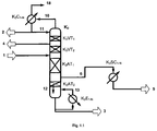
- a non-inventive variant of the method according to the invention is exemplary in Fig. 1.1 shown.
- the distillation column K 3 of this preferred embodiment has four sections, a lower stripping section (K 3 AT 2 ) and an upper stripping section (K 3 AT 1 ) and a lower reinforcing section (K 3 VT 2 ) and an upper reinforcing section (K 3 VT 1 ) on.
- the crude diaryl carbonate (1) is fed to the column between the lower reinforcement part K 3 VT 2 and the upper stripping section K 3 AT 1 .
- the upper reinforcing member preferably has a separation performance of 0 to 40, more preferably 1 to 20, most preferably 1 to 10 theoretical stages, the lower reinforcing member of preferably 1 to 40, more preferably 5 to 20, most preferably 5 to 15 theoretical stages , the upper stripping section of preferably 1 to 40, more preferably 2 to 30, most preferably 5 to 20 theoretical stages and the lower stripping section of preferably 1 to 40, more preferably 2 to 20, most preferably 2 to 15 theoretical stages.
- the fillers or ordered packings to be used are those customary for distillations, as described, for example, in US Pat Ullmann's Encyclopadie der Technischen Chemie, 4th edition, vol. 2, p. 528 ff , are described.
- Examples of random packings are Raschig or Pall and Novalox rings, Berl, Intalex or Torussjutel, Interpack stresses and as examples of ordered packs are sheet and tissue packs (such as BX packs, Montz Pak, Mellapak, Melladur, Kerapak and CY- Packing) of different materials, such as glass, stoneware, porcelain, stainless steel, plastic called.
- random packings and ordered packings which have a high surface area, good wetting and sufficient residence time of the liquid phase.
- These are, for example, Pall and Novolax rings, Berls expeditel, BX packs, Montz Pak, Mellapak, Melladur, Kerapak and CY packs.
- column bottoms such as sieve, bell, valve, tunnel bottoms are suitable. It is preferred to use random packings and structured packings, particularly preferably structured packings.
- a section within the scope of the invention is characterized in that a supply and / or removal point is located below and / or above this section.
- a section can be divided into several sections be divided if the section has more than 4, preferably more than 10 and more preferably more than 15 theoretical stages.
- the distillation column also has a single-stage or multistage (N-stage) overhead condenser K 3 C 1-N and a single-stage or multistage (N-stage) evaporator K 3 E 1-N for the bottom product.
- N-stage overhead condenser
- N-stage multistage evaporator
- both parallel and / or series connections as well as combinations of parallel and series connection are possible.
- the condensation of the vapors at the top of the distillation column can take place in one or more stages, preferably in one or two stages, in a temperature range from 40 to 250.degree. C., preferably from 50 to 200.degree. C. and more preferably from 60 to 180.degree.
- the ratio d 1 / D 1 of diameter of the vapor line from the column to the condenser (d 1 ) to column diameter of the first distillation column (D 1 ) is preferably in the range of 0.2 to 1.0, particularly preferably in the range of 0.5 to 1.
- the top condenser may be integrated into the distillation column, so that no vapor line is required between the distillation column and top condenser.
- the ratio d 1 / D 1 in this case is 1.
- the column cross section may also be adapted to the condensation progress after it has entered the top condenser.
- Such preferred embodiments are partial and exemplary in the Fig. 5a and 5b shown.
- the column diameter remains unchanged in the region of the condensation.
- the column cross-section variable it may be advantageous to make the column cross-section variable. If the guidance of the vapors to be condensed, for example, from bottom to top, the amount of steam decreases from the top down. By reducing the column diameter in the direction of the top of the column, the column cross-section available for the steam is adapted to the upwardly decreasing amount of steam. Such an embodiment is exemplary in FIG Fig. 5b shown.
- the removal of the uncondensed vapors does not necessarily have to be at the top. For example, if a design is chosen in which a plate or tube bundle is inserted from above into the column, so the removal of the non-condensed vapors may also be located laterally.
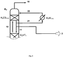
- FIG Fig. 4 Another preferred embodiment of a top condenser is shown in FIG Fig. 4 shown.
- the condensation of the vapors (10) ascending from the enrichment section, if present preferably to the upper enrichment section K 3 VT 1 takes place in one or more additional column sections (K 3 CS 1-N ) with a condensate cooled in an external circuit ,
- the liquid emerging at the lower end of this column section is partially removed (21) and fed to one or more external coolers K 3 W 1-N , which may be connected in series as well as in parallel, for removal of the condensation heat produced.
- the remaining liquid is discharged either as distillate (2) or as reflux (11) on the reinforcing member, if present preferably the upper reinforcing member K 3 VT 1 , abandoned.
- the liquid (22) above the additional column section (s) K 3 CS 1-N is returned to the distillation column.
- the column bottoms random packings or structured packings already described above can be used.
- the removal of the uncondensed vapors or inert (18) takes place above the column section (s) K 3 CS 1-N .
- the from the lower output part K 3 AT 2 in the exemplary illustration in Fig. 1.1 draining liquid 12 is evaporated in a single or multi-stage (N-stage) evaporation, wherein the vapors of the resulting vapor / liquid mixture (13) are fed back to the lower output part K 3 AT 2 .
- the evaporation is preferably carried out in a temperature range of 150 to 300 ° C, preferably from 160 to 240 ° C and particularly preferably from 180 to 230 ° C in the bottom of the column.
- the temperature at the top of the column is preferably 40 to 250 ° C, preferably 50 to 200 ° C and particularly preferably 60 to 180 ° C.
- the purified diaryl carbonate is taken off as vapor side stream (6) above the lower stripping section K 3 AT 2 and then condensed in a single or multistage (N-stage) condenser K 3 SC 1-N and removed as liquid 5.
- the condensation heat arising in the condensation in the condenser (s) K 3 SC 1-N can preferably be used to generate heating steam or to heat other process sections, such as those used in the preparation of diaryl carbonates.
- the distillation column K 3 is preferably operated at a top pressure of 1 to 1000 mbar (absolute), more preferably from 1 to 100 mbar (absolute) and most preferably from 5 to 50 mbar (absolute).
- the reflux ratio is adjusted so that the diaryl carbonate content in the distillate 10 is preferably less than 10 wt .-%, more preferably less than 5 wt .-% and most preferably less than 1 wt .-%, based on the total weight of the distillate , is.
- a reflux ratio of from 0.2 to 5, more preferably from 0.2 to 2 and very particularly preferably from 0.3 to 1.6 is preferably set, the reflux ratio in the context of the invention being the weight ratio of condensate returned to the column Head of the column extracted steam without recycled condensate corresponds.
- the mixture containing crude diaryl carbonate contains compounds having a boiling point between that of the diaryl carbonate and that of the alkylaryl carbonate by-produced during the preparation of the diaryl carbonate as an impurity, these can be removed according to the invention in a further side stream 4 of the first distillation column.
- the bottom product of the first distillation column (3) can be recycled to the transesterification from at least one dialkyl carbonate and at least one aromatic hydroxy compound to produce the dirayl carbonate to avoid catalyst losses of at least 50%, preferably at least 80% and more preferably at least 90% (24 ).
- the remaining part (25) of the bottom product can be a residue concentration (K 3 RA) for the purpose of concentrating the residue and partial recovery of the diaryl carbonate still contained in the bottom product of the first distillation column.
- the diaryl carbonate (20) recovered in the residue concentration can be returned to the first distillation column in liquid or vapor, preferably in vapor form.
- the concentrated residue (26) can either be discharged from the process or fed to a further work-up stage for the purpose of recovering the catalyst.
- the concentration of the residue (25) by means of an evaporator (K 3 E N + 1 ) takes place.
- the resulting in the evaporation vapors (20) are passed into the bottom of the first distillation column (K 3 ).
- the concentrated residue (26) can either be discharged from the process or fed to a further work-up stage for the purpose of recovering the catalyst.
- the loss of diaryl carbonate is less than 2%, preferably less than 1%, more preferably less than 0.5%, based on the amounts of purified diaryl carbonate.
- the diaryl carbonate removed in the side stream of the first distillation column is purified in at least one, preferably in a further distillation column.
- a further distillation column for purifying the diaryl carbonate taken off in the side stream of the first distillation column is also referred to below briefly as a side stream column.
- this further distillation column (sidestream column) is designed without a stripping section.
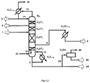
- An embodiment not according to the invention is exemplary in FIG Fig. 2.1 shown.
- the diaryl carbonate in a distillation column K 3 - as already associated with Fig. 1.1 has been described - and an additional sidestream column K 4 purified.
- the vaporous side stream 6 is the side stream column K 4 , preferably supplied to the lower part.
- the distillation column K 3 has an additional feed 9 above the lower stripping section K 3 AT 2 , via which the liquid bottom product from the sidestream column K 4 is returned to the K 3 .
- the sidestream column K 4 has at least one section.
- she will like in Fig. 2.1 shown operated as pure reinforcing member K 4 VT 1 and preferably has a separation efficiency of 1 to 50, more preferably from 2 to 30 and most preferably from 5 to 20 theoretical stages.
- the sidestream column K 4 is operated at a top pressure of 1 to 1000 mbar (absolute), more preferably from 1 to 100 mbar (absolute) and most preferably from 5 to 50 mbar (absolute).
- a reflux ratio of from 0.1 to 10, more preferably from 0.2 to 5 and most preferably from 0.2 to 2 is preferably set.
- the condensation of the vapors (7) at the head of the sidestream column K 4 may be one or more stages in a top condenser K 4 C 1-N. It is preferably carried out in one or two stages in a temperature range of 70 to 250 ° C, particularly preferably from 90 to 230 ° C and most preferably from 90 to 210 ° C.
- the waste heat produced during the condensation can preferably be used to generate heating steam or to heat other process sections, such as those used in the preparation of diaryl carbonates.
- the condensate obtained in the condensation is partially abandoned again as reflux (8) on the sidestream column. Of the remaining part of the condensate is taken off as distillate (5) (purified diaryl carbonate). Inert and / or uncondensed vapors (19) are discharged.
- this further distillation column is designed both with at least one enrichment part and with at least one stripping section.
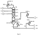
- a non-inventive variant of this embodiment is exemplified in Fig. 2.3 shown.
- sidestream column K 4 has both a driven part K 4 AT 1 and a reinforcing part K 4 AT 2 .
- the vaporous side stream 6 of the first distillation column K 3 can first be condensed in a single-stage or multistage side stream condenser K 3 SC 1-N and then fed to the side stream column K 4 .
- the sidestream column K 4 is operated at a top pressure of 1 to 1000 mbar (absolute), preferably 1 to 100 mbar (absolute) and more preferably 5 to 50 mbar (absolute). This results in the bottom of a temperature of 150 to 300 ° C, preferably from 160 to 240 ° C and particularly preferably 180 to 230 ° C ° C.
- the side stream column K 4 according to Fig. 2.3 has a total separation power of 5 to 100 stages, preferably 10 to 80 stages, more preferably 30 to 80 stages, wherein the reinforcing member thereof has a separation performance of 1 to 99, preferably 1 to 79 and more preferably 2 to 79.
- the sidestream column K 4 is operated at a reflux ratio of 0.5 to 20, preferably 1 to 10 and particularly preferably 1 to 5.
- the condensation of the vapors (7) at the head of the sidestream column K 4 may be one or more stages in a top condenser K 4 C 1-N. It is preferably carried out in one or two stages in a temperature range of 70 to 250 ° C, particularly preferably from 90 to 230 ° C and most preferably from 90 to 210 ° C.
- the waste heat produced during the condensation can preferably be used to generate heating steam or to heat other process sections, such as those used in the preparation of diaryl carbonates.
- the condensate obtained in the condensation is partially abandoned again as reflux (8) on the sidestream column. The remainder of the condensate is taken off as distillate (5) (purified diaryl carbonate). Uncondensed vapors (19) are discharged.
- the evaporation of the effluent from the stripping section K 4 AT 1 of the sidestream column liquid (23) can also be carried out in one or more stages in an evaporator K 4 E 1-N .
- the bottom product (9) of the side stream column K 4 can then be wholly or partially discharged from the process and / or wholly or partially recycled to the distillation column K 3 .
- the above-described particularly preferred embodiment of the process according to the invention using a sidestream column is particularly suitable for the purification of diaryl carbonates with increased requirements in terms of their quality.
- Such increased requirements may, for example, be in a reduced proportion of high-boiling secondary components, the proportion thereof in the diaryl carbonate being from 10 to 100% by weight, preferably from 20 to 90% by weight and more preferably from 25 to 80% by weight, compared to the process with only a distillation column can be reduced.
- the further distillation column is integrated into the first distillation column.
- the enrichment section of this further column is integrated into the first distillation column (K 3 ).
- a variant of this embodiment is exemplified in Fig. 2.2 shown. In this case, part of the vapors (6) coming from the lower stripping section of the first distillation column (K 3 AT 2 ) enters an integrated enrichment section (K 4 VT 1 ) in order to reduce the content of high-boiling components.
- the first distillation column is designed as a dividing wall column.
- Dividing wall columns are also suitable for the separation of a mixture into three fractions, ie top product, bottom product and side stream with high purity.
- the dividing wall column has a generally vertically arranged dividing wall, which separates the feed side from the withdrawal side for the side stream from each other.
- the partition is preferably not continuous over the entire length of the column. Usually there is above the partition still a reinforcement part and below the partition nor a stripping section.
- In the area of the dividing wall are located both on the inlet and on the withdrawal side for the Side stream preferably at least 2 sections.
- On the inlet side serves an upper section for reducing the high boiler contained in the feed and a lower section for reducing the low boilers contained in the feed.
- On the removal side for the side stream is also an upper section above the removal, which serves to reduce the low boilers from the reinforcing member.
- a lower section, which is arranged below the removal serves to reduce high boilers, which come from the stripping section below the partition.
- the division of the effluent from the reinforcing member liquid depends on the requirements of the specific separation task and can be influenced by design and control engineering measures. The same applies to the, coming from the driven part, steam flow.
- Dividing wall columns are known in the art and, for example, in DE-A 33 02 525 or DE-A 199 14 966 described.
- the dividing wall column preferably has in each case an upper and lower section on the inlet side of the dividing wall and on the withdrawal side of the dividing wall, feed and removal respectively between the upper part and lower section.
- the enrichment part of the dividing wall column has two sections, i. a lower reinforcing member and an upper reinforcing member.
- the dividing wall column has at least seven sections, comprising at least one stripping section in the lower part of the column, respectively an upper and lower section on the inlet side of the partition and on the discharge side of the partition and an upper and lower reinforcing member in upper part of the column.
- the dividing wall in such a dividing wall column is preferably arranged in the longitudinal direction of the column. It prevents both vapor-side and liquid-side mass transfer between inlet and outlet side.
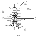
- FIG. 3.1 An exemplary embodiment of the inventive method with a dividing wall column with seven sections is exemplified in Fig. 3.1 shown.
- the dividing wall column K 3 in Fig. 3.1 has a stripping section K 3 AT 1 in the lower part of the column K 3 , in each case an upper section K 3 TLO and lower section K 3 TLU on the inlet side of the partition wall T. and an upper section K 3 TRO and lower section K 3 TRU on the discharge side of the partition wall T and an upper reinforcement section K 3 VT 1 and lower reinforcement section K 3 VT 2 in the upper part of the column.
- the crude diaryl carbonate (1) is fed between the upper section K 3 TLO and the lower section K 3 TLU on the inlet side of the dividing wall T of the column, the purified diaryl carbonate (5) is between the upper section K 3 TRO and the lower section K 3 TRU taken on the withdrawal side of the partition T of the column.
- the upper section K 3 TLO located on the inflow side of the partition serves to separate high boilers which are contained in the inlet.
- the lower section K 3 TLU on the inlet side of the dividing wall is used for the separation of low-boiling components contained in the crude diaryl carbonate (1).
- the upper section K 3 TRO located on the removal side of the dividing wall serves to separate low-boiling components which are contained in the liquid stream (15) emerging from the enrichment part K 3 VT 2 in the upper part of the column.
- the lower section of the withdrawal side K 3 TRU is used for the separation of high boilers, which are contained in the emerging from the stripping section K 3 AT 1 steam flow (17).
- the removal of the purified diaryl carbonate on the removal side of the partition can be liquid or vapor.
- the dividing wall can in each case be arranged displaced in the column to the removal side or to the inlet side and thus reduce or enlarge the cross section of the respective side relative to the other.
- the cross section of the withdrawal side of the column is preferably greater than the cross section of the inlet side, i. it gets more steam from the stripping section in the sampling side.
- the cross section of the feed side of the column is preferably identical to the cross section of the withdrawal side.
- the ascending steam from the stripping section K 3 AT 1 is supplied to 5 to 90%, preferably to 10 to 80 and particularly preferably to 20 to 60% of the inlet side of the partition wall (16).
- the side stream (6) taken off in vapor form is preferably condensed in one or more side stream condenser (s) K 3 SC 1-N and discharged as liquid diaryl carbonate stream (5).
- the upper reinforcement part of such a dividing wall column preferably has a separation capacity of 0 to 40, more preferably 1 to 20, most preferably 1 to 10 theoretical stages, the lower reinforcement portion of preferably 1 to 40, particularly preferably 5 to 20, most preferably 5 to 15 theoretical stages, the stripping section of preferably 1 to 40, more preferably 2 to 20, most preferably 2 to 15 theoretical stages.
- the upper section K 3 TLO and lower section K 3 TLU on the inlet side of the partition wall and the upper section K 3 TRO and lower section K 3 TRU on the removal side of the partition preferably each have a separation efficiency of 1 to 40, more preferably 2 to 20 , most preferably 5 to 20 theoretical stages.
- the fillers or ordered packings to be used are those customary for distillations, as described, for example, in US Pat Ullmann's Encyclopadie der Technischen Chemie, 4th edition, vol. 2, p. 528 ff , are described.
- Examples of random packings are Raschig or Pall and Novalox rings, Berl, Intalex or Torussjutel, Interpack stresses and as examples of ordered packs are sheet and tissue packs (such as BX packs, Montz Pak, Mellapak, Melladur, Kerapak and CY- Packing) of different materials, such as glass, stoneware, porcelain, stainless steel, plastic called.
- These are, for example, Pall and Novolax rings, Berls expeditel, BX packs, Montz Pak, Mellapak, Melladur, Kerapak and CY packs.
- column bottoms such as sieve, bell, valve, tunnel bottoms are suitable.
- the dividing wall column also has a single-stage or multistage (N-stage) overhead condenser K 3 C 1-N and a single-stage or multistage (N-stage) evaporator K 3 E 1-N for the bottom product.
- the condensation of the vapors at the top of the dividing wall column can take place in one or more stages, preferably in one or two stages, in a temperature range from 40 to 250.degree. C., preferably from 50 to 200.degree. C. and more preferably from 60 to 180.degree.
- the condensation in the top condenser the different embodiments of the condensers already mentioned above for the distillation columns are possible.
- the effluent from the stripping section K 3 AT 1 liquid (12) is evaporated in a single or multi-stage (N-stage) evaporation, wherein the vapors of the resulting vapor / liquid mixture (13) again supplied to the lower output part K 3 AT 1 become.
- the evaporation is preferably carried out in a temperature range of 100 to 250 ° C, preferably from 150 to 240 ° C and particularly preferably from 180 to 220 ° C.
- the dividing wall column is operated at a top pressure of 1 to 1000 mbar (absolute), more preferably from 1 to 100 mbar (absolute), and most preferably from 5 to 50 mbar (absolute).
- the reflux ratio is adjusted so that the diaryl carbonate content in the distillate 10 is preferably less than 10 wt .-%, more preferably less than 5 wt .-% and most preferably less than 1 wt .-%, based on the total weight of the distillate , is.
- a reflux ratio of from 0.2 to 5, more preferably from 0.2 to 2 and very particularly preferably from 0.3 to 1.6 is preferably set, the reflux ratio in the context of the invention being the weight ratio of condensate returned to the column Head of the column extracted steam without recycled condensate corresponds.
- the diaryl carbonate to be purified contains compounds having a boiling point between that of the diaryl carbonate and that of the alkylaryl carbonate formed as intermediate during the preparation of the diaryl carbonate as an impurity, these can be taken off in a further side stream 4 of the dividing wall column.
- Example 1 (Comparative Example): DPC purification in a first distillation column (fine distillation) with a side stream column according to FIG. 2.1
- the fine distillation (K 3 ) consists of four sections, an upper reinforcement part with 2, a lower reinforcement part with 12, an upper output part with 10 and a lower output part with 9 theoretical stages.
- the condensation of the vapors leaving the top of the column in the overhead condenser (K 3 C 1 ) and the partial evaporation of the effluent from the lower stripping section (K 3 AT 2 ) in the evaporator K 3 E 1 for the bottom product is carried out in one stage.
- the column is operated at a top pressure of 15 mbar and a reflux ratio of 0.7.
- distillate (2) a stream of 69.9 / 28.3 / 1.2 / 0.5 wt .-% MPC / phenol / DMC / DPE.
- K 3 VT 1 0.02 kg / h of liquid for the purpose of discharge of intermediate boilers in the side stream (4) are removed.
- 192.8 kg / h of a vaporous side stream (6) containing 99.9% by weight of DPC are taken off below the upper reinforcing part K 3 VT 1 .
- the bottom product (3) is 20.8 kg / h of a mixture with 69.8 / 29.6 / 0.5 wt .-% DPC / Ti (PhO) 4 / salol.
- K 3 RA residue concentration
- the remaining bottom product (24) is again the two-stage transesterification for producing the DPC-containing stream (1) recycled. This reduces catalyst loss by 90%.
- the vaporous side stream (6) is fed to a side stream column K 4 .
- the sidestream column K 4 is operated under the same pressure conditions as the fine distillation in the first distillation column K 3 and at a reflux ratio of 0.5.
- the vapors (7) leaving the top of the side stream column K 4 are condensed in a two-stage condensation in the condensers K 4 C 1-N , the heat of condensation being used either to generate steam or to heat other process sections of the DPC production.
- Example 2 DPC purification in a dividing wall column with liquid side stream take-off
- a dividing wall column according to Fig. 3.1 used.
- the dividing wall column K 3 consists of a reinforcing part with 2 sections.
- the upper section K 3 VT 1 has a separation capacity of 2, the section below K 3 VT 2 a separation capacity of 12 theoretical stages.
- Below the upper reinforcing member K 3 VT 1 there is the possibility of removing a liquid stream (4) for discharging diphenyl ether.
- the column is partitioned by a vertically arranged partition T. There are at least 2 sections each on the extraction and feed side of this partition. On the inlet side of the partition, the task of the inlet (1). On the withdrawal side there is a liquid removal of the purified diphenyl carbonate (5).
- the upper section K 3 TLO located on the inlet side of the partition serves to separate high-boiling components contained in the inlet (1).
- the lower section of the inlet side K 3 TLU is used to separate low boilers contained in the feed (1).
- the upper section K 3 TRO located on the removal side of the dividing wall serves to separate low-boiling components contained in the liquid stream (15) emerging from the reinforcing part.
- the lower section of the Withdrawal side K 3 TRU is used to separate high boilers which are contained in the vapor stream (17) leaving the stripping section.
- the stripping section K 3 AT 1 has a separation capacity of 14 theoretical stages and serves to concentrate the high boiler.
- the steam (10) leaving the enrichment section is condensed in a condenser K 3 C 1-N and partly returned to the column as reflux (11).
- the effluent from the stripping section liquid (12) is partially evaporated in an evaporator K 3 E 1-N .
- the column is operated at a top pressure of 15 mbar.
- the feed rate (1) to the column K 3 is 236.6 kg / h. It contains 62.8 / 24.2 / 9.8 / 0.4 / 0.1 / 0.03 / 2.6 wt% DPC / MPC / phenol / DMC / DPE / Salol / Ti (PhO) 4 ,
- the distillate (2) obtained is 81.8 kg / h of a mixture of 69.9 / 28.4 / 1.15 / 0.05 / 0.5% by weight MPC / phenol / DMC / DPC / DPE.
- the bottom product (3) is 20.6 kg / h of a mixture of 69.7 / 29.8 / 0.41 wt .-% DPC / Ti (PhO) 4 / salol.
- the diphenyl carbonate removed in the side stream (5) (134 kg / h) has a purity of 99.97 wt .-% and contains only 280 ppm salol.
- the effluent from the reinforcing member liquid is applied to 25% on the inlet side of the partition, ie above K 3 TLO, and to 75% on the removal side of the partition, ie on K 3 TRO.
- the rising from the stripping section K 3 AT 1 steam is divided in equal parts on the inlet and outlet side of the partition.
- Example 3 DPC purification in a dividing wall column with vaporous side stream take-off
- a dividing wall column according to Fig. 3.2 used.
- the dividing wall column K 3 consists of a reinforcing part with 2 sections.
- the upper section K 3 VT 1 has a separation capacity of 2, the section below K 3 VT 2 a separation capacity of 13 theoretical stages.
- Below the upper reinforcing member K 3 VT 1 there is the possibility of removing a liquid stream (4) for discharging diphenyl ether.
- the column is partitioned by a vertically arranged partition T.
- On the inlet and the discharge side of this partition are respectively at least 2 sections.
- On the inlet side of the partition the task of the inlet (1).
- On the withdrawal side a vaporous removal of the purified diphenyl carbonate (6) takes place.
- the located on the inlet side of the partition upper section K 3 TLO is used to separate high boilers that are included in the inlet 1.
- the lower section of the feed side K 3 TLU is used to separate low-boiling components contained in feed 1.
- the upper section K 3 TRO located on the removal side of the dividing wall serves to separate low-boiling components contained in the liquid stream 15 emerging from the reinforcing part.
- the lower section of the withdrawal side K 3 TRU serves to separate high boilers which are contained in the steam flow (17) exiting from the stripping section.
- the stripping section K 3 AT 1 has a separation capacity of 14 theoretical stages and serves to concentrate the high boiler.
- the steam (10) leaving the enrichment section is condensed in a condenser K 3 C 1-N and partly returned to the column as reflux (11).
- the effluent from the stripping section liquid (12) is partially evaporated in an evaporator K 3 E 1-N .
- the column is operated at a top pressure of 15 mbar.
- the diphenyl carbonate (5) removed in the side stream and subsequently condensed has a purity of 99.97% by weight and contains only 290 ppm salol.
- the effluent from the reinforcing member liquid is applied to 25% on the inlet side of the partition, ie above K 3 TLO, and to 75% on the removal side of the partition, ie on K 3 TRO.
- the ascending from the stripping section K 3 AT 1 steam is divided into 25% on the inlet and 75% on removal side of the partition.
Description
Gegenstand der vorliegenden Erfindung ist ein spezielles Verfahren zur Reinigung von Diarylcarbonaten.The present invention is a special process for the purification of diaryl carbonates.
Die Aufreinigung von Diarylcarbonat ist aufgrund der hohen Anforderungen an deren Reinheit für die Herstellung von qualitativ hochwertigen Polycarbonaten mittels Schmelzeumesterung von großer Bedeutung. Diarylcarbonate hergestellt aus Umesterung einer aromatischen Hydroxyverbindung mit einem Alkylcarbonat können sowohl hochsiedende als auch mittelsiedende Nebenkomponenten sowie Katalysatorreste als Verunreinigungen enthalten. Hochsiedende Komponenten - oft auch als Schwersieder bezeichnet - im Sinne dieses Herstellverfahrens sind solche, deren Siedepunkt oberhalb desjenigen des Diarylcarbonats liegen. Mittelsiedende Komponenten - oft auch als Zwischensieder bezeichnet - im Sinne dieses Herstellverfahrens sind solche, deren Siedepunkt zwischen dem des Diarylcarbonats und dem des während der Herstellung des Diarylcarbonats als Nebenprodukt gebildeten Alkylarylcarbonats liegt. All diese Verunreinigungen führen zu erheblicher qualitativer Beeinträchtigung der herzustellenden Polycarbonate und müssen vor der Weiterverarbeitung der Diarylcarbonate durch entsprechende Aufreinigung entfernt werden.The purification of diaryl carbonate is due to the high demands on their purity for the production of high quality polycarbonates by melt transesterification of great importance. Diaryl carbonates prepared from transesterification of an aromatic hydroxy compound with an alkyl carbonate can contain both high-boiling and medium-boiling secondary components and catalyst residues as impurities. High-boiling components - often referred to as high boilers - in the sense of this preparation are those whose boiling point above that of the diaryl carbonate. Medium-boiling components-often also referred to as intermediates-in the context of this preparation process are those whose boiling point lies between that of the diaryl carbonate and that of the alkylaryl carbonate formed as a by-product during the preparation of the diaryl carbonate. All of these impurities lead to considerable deterioration of the quality of the polycarbonates to be produced and must be removed by further purification before further processing of the diaryl carbonates.
In der
In der
In
In der
Es bestand demnach weiterhin Bedarf an einem Verfahren zur Aufreinigung von Diarylcarbonaten bei dem mit möglichst einfacher apparativer und günstiger energetischer Ausführung Katalysatorreste und hochsiedende Nebenkomponenten sowie gegebenenfalls auch mittelsiedende Nebenkomponenten als Verunreinigungen entfernt werden können.There was accordingly a continuing need for a process for the purification of diaryl carbonates in which catalyst residues and high-boiling secondary components as well as, if appropriate, also medium-boiling secondary components may be removed as impurities with the simplest possible apparatus and favorable energetic design.
Die Aufgabe, die der vorliegenden Erfindung zugrunde lag, bestand darin, ein solches Verfahren bereitzustellen.The object underlying the present invention was to provide such a method.
Überraschend wurde nun gefunden, dass die destillative Aufreinigung von Diarylcarbonaten auch bei geringem apparativen und energetischen Aufwand durchgeführt werden kann, wenn die zu reinigenden Diarylcarbonate Katalysatorreste und hochsiedende Nebenkomponenten sowie gegebenenfalls auch mittelsiedende Nebenkomponenten als Verunreinigungen enthalten. Dabei kann bevorzugt sogar die bei der Destillation anfallende Abwärme energetisch genutzt werden.Surprisingly, it has now been found that the distillative purification of diaryl carbonates can also be carried out with low expenditure on equipment and energy if the diaryl carbonates to be purified contain catalyst residues and high-boiling secondary components and, if appropriate, also medium-boiling secondary components as impurities. In this case, preferably even the waste heat produced during the distillation can be used energetically.
Gegenstand der vorliegenden Erfindung ist ein Verfahren zur Reinigung von Diarylcarbonaten in wenigstens einer Destillationskolonne enthaltend wenigstens einen Verstärkungsteil im oberen Teil der Kolonne und wenigstens einen Abtriebsteil im unteren Teil der Kolonne, wobei
- das zu reinigende Diarylcarbonat durch Umesterung aus wenigstens einem Dialkylcarbonat und wenigstens einer aromatischen Hydroxyverbindung in Gegenwart wenigstens eines Umesterungskatalysator hergestellt wurde und Katalysator aus der Herstellung des Diarylcarbonats als Verunreinigung enthält, und
- das gereinigte Diarylcarbonat im Seitenstrom der ersten Destillationkolonne entnommen wird;
- the diaryl carbonate to be purified has been prepared by transesterification from at least one dialkyl carbonate and at least one aromatic hydroxy compound in the presence of at least one transesterification catalyst and catalyst from the preparation of the diaryl carbonate as an impurity, and
- the purified diaryl carbonate is taken off in the sidestream of the first distillation column;
Im Rahmen der Erfindung zu reinigende Diarylcarbonate sind bevorzugt solche der allgemeinen

Diarylcarbonate der allgemeinen Formel (I) sind beispielsweise: Diphenylcarbonat, Methylphenylphenyl-carbonate und Di-(methylphenyl)-carbonate, auch als Gemisch, wobei die Stellung der Methylgruppe an den Phenylringen beliebig sein kann, sowie Dimethylphenyl-phenyl-carbonate und Di-(dimethylphenyl)-carbonate, auch als Gemisch, wobei die Stellung der Methylgruppen an den Phenylringen beliebig sein kann, Chlorphenyl-phenyl-carbonate und Di-(chlorphenyl)-carbonate, wobei die Stellung der Methylgruppe an den Phenylringen beliebig sein kann, 4-Ethylphenyl-phenyl-carbonat, Di-(4-ethylphenyl)-carbonat, 4-n-Propylphenyl-phenyl-carbonat, Di-(4-n-propylphenyl)-carbonat, 4-iso-Propylphenyl-phenyl-carbonat, Di-(4-iso-propylphenyl)-carbonat, 4-n-Butylphenyl-phenyl-carbonat, Di-(4-n-butylphenyl)-carbonat, 4-iso-Butylphenyl-phenyl-carbonat, Di-(4-iso-butylphenyl)-carbonat, 4-tert-Butylphenyl-phenyl-carbonat, Di-(4-tert-butylphenyl)-carbonat, 4-n-Pentylphenyl-phenyl-carbonat, Di-(4-n-pentylphenyl)-carbonat, 4-n-Hexylphenyl-phenyl-carbonat, Di-(4-n-hexylphenyl)-carbonat, 4-iso-Octylphenyl-phenyl-carbonat, Di-(4-iso-octylphenyl)-carbonat,4-n-Nonylphenyl-phenyl-carbonat, Di-(4-n-nonylphenyl)-carbonat, 4-Cyclohexylphenyl-phenyl-carbonat, Di-(4-cyclohexylphenyl)-carbonat, 4-(1-Methyl-1-phenylethyl)-phenyl-phenyl-carbonat, Di-[4-(1-methyl-1-phenylethyl)-phenyl]-carbonat, Biphenyl-4-yl-phenyl-carbonat, Di-(biphenyl-4-yl)-carbonat, (1-Naphthyl)-phenyl-carbonat, (2-Naphthyl)-phenyl-carbonat, Di-(1-naphthyl)-carbonat, Di-(2-naphthyl)-carbonat, 4-(1-Naphthyl)-phenyl-phenyl-carbonat, 4-(2-Naphthyl)-phenyl-phenyl-carbonat, Di-[4-(1-naphthyl)phenyl]-carbonat, Di-[4-(2-naphthyl)phenyl]-carbonat, 4-Phenoxyphenyl-phenyl-carbonat, Di-(4-phenoxyphenyl)-carbonat, 3-Pentadecylphenyl-phenyl-carbonat, Di-(3-pentadecylphenyl)-carbonat, 4-Tritylphenylphenyl-carbonat, Di-(4-tritylphenyl)-carbonat, Methylsalicylat-phenyl-carbonat, Di-(methylsalicylat)-carbonat, Ethylsalicylat-phenyl-carbonat, Di-(ethylsalicylat)-carbonat, n-Propylsalicylat-phenyl-carbonat, Di-(n-propylsalicylat)-carbonat, iso-Propylsalicylat-phenyl-carbonat, Di-(iso-propylsalicylat)-carbonat, n-Butylsalicylat-phenyl-carbonat, Di-(n-butylsalicylat)-carbonat, iso-Butylsalicylat-phenyl-carbonat, Di-(iso-butylsalicylat)-carbonat, tert-Butylsalicylat-phenyl-carbonat, Di-(tert-butylsalicylat)-carbonat, Di-(phenylsalicylat)-carbonat und Di-(benzylsalicylat)-carbonat.Diarylcarbonates of the general formula (I) are, for example: diphenyl carbonate, methylphenylphenyl carbonates and di (methylphenyl) carbonates, also as a mixture, where the position of the methyl group on the phenyl rings may be arbitrary, and dimethylphenyl-phenyl-carbonates and di ( dimethylphenyl) carbonates, also as a mixture, wherein the position of the methyl groups on the phenyl rings may be arbitrary, chlorophenyl-phenyl-carbonates and di (chlorophenyl) carbonates, wherein the position of the methyl group on the phenyl rings may be arbitrary, 4-ethylphenyl phenyl carbonate, di- (4-ethylphenyl) carbonate, 4-n-propylphenyl phenyl carbonate, di- (4-n-propylphenyl) carbonate, 4-iso-propylphenyl-phenyl-carbonate, di- (4-iso-propylphenyl) -carbonate, 4-n-butylphenyl-phenyl-carbonate, di- (4-n-butylphenyl) -carbonate, 4-iso-butylphenyl- phenyl carbonate, di (4-isobutylphenyl) carbonate, 4-tert-butylphenyl phenyl carbonate, di- (4-tert-butylphenyl) carbonate, 4-n-pentylphenyl phenyl carbonate, di- (4-n-pentylphenyl) carbonate, 4-n-hexylphenyl-phenyl carbonate, di (4-n-hexylphenyl) carbonate, 4-iso-octylphenyl-phenyl carbonate, di (4-iso-octylphenyl ) carbonate, 4-n-nonylphenyl phenyl carbonate, di- (4-n-nonylphenyl) carbonate, 4-cyclohexylphenyl phenyl carbonate, di (4-cyclohexylphenyl) carbonate, 4- (1-methyl 1-phenylethyl) phenyl phenyl carbonate, di- [4- (1-methyl-1-phenylethyl) phenyl] carbonate, biphenyl-4-yl phenyl carbonate, di- (biphenyl-4-yl ) carbonate, (1-naphthyl) phenyl carbonate, (2-naphthyl) phenyl carbonate, di (1-naphthyl) carbonate, di- (2-naphthyl) carbonate, 4- (1-naphthyl ) -phenyl-phenyl carbonate, 4- (2-naphthyl) -phenyl-phenyl carbonate, di- [4- (1-naphthyl) -phenyl] -carbonate, di- [4- (2-na phthyl) phenyl] carbonate, 4-phenoxyphenyl phenyl carbonate, di (4-phenoxyphenyl) carbonate, 3-pentadecylphenyl phenyl carbonate, di- (3-pentadecylphenyl) carbonate, 4-trityl phenyl phenyl carbonate, di - (4-tritylphenyl) carbonate, methyl salicylate phenyl carbonate, di (methyl salicylate) carbonate, ethyl salicylate phenyl carbonate, di (ethyl salicylate) carbonate, n-propyl salicylate phenyl carbonate, di (n-) propyl salicylate) carbonate, iso-propyl salicylate phenyl carbonate, di- (iso-propyl salicylate) carbonate, n-butyl salicylate phenyl carbonate, di (n-butyl salicylate) carbonate, iso-butyl salicylate phenyl carbonate, Di - (Iso-butylsalicylate) carbonate, tert-butyl salicylate phenyl carbonate, di (tert-butylsalicylate) carbonate, di (phenyl salicylate) carbonate and di (benzyl salicylate) carbonate.
Bevorzugte Diarylcarbonate sind: Diphenylcarbonat, 4-tert-Butylphenyl-phenyl-carbonat, Di-(4-tert-butylphenyl)-carbonat, Biphenyl-4-yl-phenyl-carbonat, Di-(biphenyl-4-yl)-carbonat, 4-(1-Methyl-1-phenylethyl)-phenyl-phenyl-carbonat und Di-[4-(1-methyl-1-phenylethyl)-phenyl]-carbonat.Preferred diaryl carbonates are: diphenyl carbonate, 4-tert-butylphenyl phenyl carbonate, di (4-tert-butylphenyl) carbonate, biphenyl-4-yl phenyl carbonate, di (biphenyl-4-yl) carbonate, 4- (1-methyl-1-phenylethyl) -phenyl-phenyl-carbonate and di- [4- (1-methyl-1-phenylethyl) -phenyl] -carbonate.
Besonders bevorzugt ist Diphenylcarbonat.Particularly preferred is diphenyl carbonate.
Dialkylcarbonate im Rahmen der Erfindung sind solche der Formel (II)

Bevorzugte Dialkylcarbonate sind Dimethylcarbonat, Diethylcarbonat, Di(n-propyl)carbonat, Di(iso-propyl)carbonat, Di(n-butyl)carbonat, Di(sec-butyl)carbonat, Di(tert-butyl)carbonat oder Dihexylcarbonat. Besonders bevorzugt sind Dimethylcarbonat oder Diethylcarbonat. Ganz besonders bevorzugt ist Dimethylcarbonat.
Aromatische Hydroxyverbindungen im Rahmen der Erfindung sind bevorzugt solche der allgemeinen Formel (III)
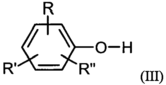
Aromatic hydroxy compounds in the context of the invention are preferably those of the general formula (III)
Solche aromatischen Hydroxyverbindungen sind beispielsweise: Phenol, o-, m- oder p-Kresol, auch als Gemisch der Kresole, Dimethylphenol, auch als Gemisch, wobei die Stellung der Methylgruppen am Phenolring beliebig sein kann, z.B. 2,4-, 2,6-, oder 3,4-Dimethylphenol, o-, m- oder p-Chlorphenol, o-, m- oder p-Ethylphenol, o-, m- oder p-n-Propylphenol, 4-iso-Propylphenol, 4-n-Butylphenol, 4-iso-Butylphenol, 4-tert-Butylphenol, 4-n-Pentylphenol, 4-n-Hexylphenol, 4-iso-Octylphenol, 4-n-Nonylphenol, o-, m- oder p-Methoxyphenol, 4-Cyclohexylphenol, 4-(1-Methyl-1-phenylethyl)-phenol, Biphenyl-4-ol, 1-Naphthol, 2-1-Naphthol, 4-(1-Naphthyl)phenol, 4-(2-Naphthyl)-phenol, 4-Phenoxyphenol, 3-Pentadecylphenol, 4-Tritylphenol, Methylsalicylsäure, Ethylsalicylsäure, n-Propylsalicylsäuret, iso-Propylsalicylsäure, n-Butylsalicylsäure, iso-Butylsalicylsäure, tert-Butylsalicylsäure, Phenylsalicylsäure und Benzylsalicylsäure.Such aromatic hydroxy compounds are, for example: phenol, o-, m- or p-cresol, also as a mixture of cresols, dimethylphenol, also as a mixture, wherein the position of the methyl groups on the phenol ring may be arbitrary, e.g. 2,4-, 2,6- or 3,4-dimethylphenol, o-, m- or p-chlorophenol, o-, m- or p-ethylphenol, o-, m- or pn-propylphenol, 4-iso -Propylphenol, 4-n-butylphenol, 4-iso-butylphenol, 4-tert-butylphenol, 4-n-pentylphenol, 4-n-hexylphenol, 4-iso-octylphenol, 4-n-nonylphenol, o-, m- or p-methoxyphenol, 4-cyclohexylphenol, 4- (1-methyl-1-phenylethyl) phenol, biphenyl-4-ol, 1-naphthol, 2-1-naphthol, 4- (1-naphthyl) phenol, 4- (2-naphthyl) -phenol, 4-phenoxyphenol, 3-pentadecylphenol, 4-tritylphenol, methylsalicylic acid, ethylsalicylic acid, n-propylsalicylic acid, iso-propylsalicylic acid, n-butylsalicylic acid, iso-butylsalicylic acid, tert-butylsalicylic acid, phenylsalicylic acid and benzylsalicylic acid.
Bevorzugte aromatischen Hydroxyverbindungen sind Phenol, 4-tert-Butylphenol, Biphenyl-4-ol und 4-(1-Methyl-1-phenylethyl)-phenol.Preferred aromatic hydroxy compounds are phenol, 4-tert-butylphenol, biphenyl-4-ol and 4- (1-methyl-1-phenylethyl) phenol.
Besonders bevorzugt ist Phenol.Particularly preferred is phenol.
Sowohl die vorangehend genannten Dialkylcarbonate als auch die aromatischen Hydroxyverbindungen sind dem Fachmann bekannt und kommerziell erhältlich oder können nach dem Fachmann ebenfalls bekannten Verfahren hergestellt werden.Both the aforementioned dialkyl carbonates and the aromatic hydroxy compounds are known to the person skilled in the art and are commercially available or can be prepared by processes which are likewise known to the person skilled in the art.
C1-C4-Alkyl steht im Rahmen der Erfindung beispielsweise für Methyl, Ethyl, n-Propyl, isoPropyl, n-Butyl, sec.-Butyl, tert.-Butyl, C1-C6-Alkyl darüber hinaus beispielsweise für n-Pentyl, 1-Methylbutyl, 2-Methylbutyl, 3-Methylbutyl, neo-Pentyl, 1-Ethylpropyl, n-Hexyl, 1,1-Dimethylpropyl, 1,2-Dimethylpropyl, 1,2-Dimethylpropyl, 1-Methylpentyl, 2-Methylpentyl, 3-Methylpentyl, 4-Methylpentyl, 1,1-Dimethylbutyl, 1,2-Dimethylbutyl, 1,3-Dimethylbutyl, 2,2-Dimethylbutyl, 2,3-Dimethylbutyl, 3,3-Dimethylbutyl, 1-Ethylbutyl, 2-Ethylbutyl, 1,1,2-Trimethylpropyl, 1,2,2-Trimethylpropyl, 1-Ethyl-1-methylpropyl, 1-Ethyl-2-methylpropyl oder 1-Ethyl-2-methylpropyl, C1-C34-Alkyl darüber hinaus beispielsweise für n-Heptyl und n-Octyl, n-Nonyl, n-Decyl, n-Dodecyl, n-Tridecyl, n-Tetradecyl, n-Hexadecyl oder n-Octadecyl. Gleiches gilt für den entsprechenden Alkylrest beispielsweise in Aralkyl- bzw. Alkylarylresten. Alkylenreste in den entsprechenden Hydroxyalkyl- oder Aralkyl- bzw. Alkylarylresten stehen beispielsweise für die den vorangehenden Alkylresten entsprechenden Alkylenreste. In the context of the invention, C 1 -C 4 -alkyl is, for example, methyl, ethyl, n-propyl, isopropyl, n-butyl, sec-butyl, tert-butyl, C 1 -C 6 -alkyl, moreover, for example, n -Pentyl, 1-methylbutyl, 2-methylbutyl, 3-methylbutyl, neo-pentyl, 1-ethylpropyl, n-hexyl, 1,1-dimethylpropyl, 1,2-dimethylpropyl, 1,2-dimethylpropyl, 1-methylpentyl, 2 -methylpentyl, 3-methylpentyl, 4-methylpentyl, 1,1-dimethylbutyl, 1,2-dimethylbutyl, 1,3-dimethylbutyl, 2,2-dimethylbutyl, 2,3-dimethylbutyl, 3,3-dimethylbutyl, 1-ethylbutyl, 2 Ethylbutyl, 1,1,2-trimethylpropyl, 1,2,2-trimethylpropyl, 1-ethyl-1-methylpropyl, 1-ethyl-2-methylpropyl or 1-ethyl-2-methylpropyl, C 1 -C 34 alkyl, moreover for example, for n-heptyl and n-octyl, n-nonyl, n-decyl, n-dodecyl, n-tridecyl, n-tetradecyl, n-hexadecyl or n-octadecyl. The same applies to the corresponding alkyl radical, for example in aralkyl or alkylaryl radicals. Alkylene radicals in the corresponding hydroxyalkyl or aralkyl or alkylaryl radicals are, for example, the alkylene radicals corresponding to the preceding alkyl radicals.
Aryl steht für einen carbocyclischen aromatischen Rest mit 6 bis 34 Gerüstkohlenstoffatomen. Gleiches gilt für den aromatischen Teil eines Arylalkylrestes, auch Aralkylrest genannt, sowie für Arylbestandteile komplexerer Gruppen, wie z.B. Arylcarbonylresten.Aryl represents a carbocyclic aromatic radical having 6 to 34 skeleton carbon atoms. The same applies to the aromatic part of an arylalkyl radical, also called aralkyl radical, and to aryl constituents of more complex groups, such as e.g. Arylcarbonyl.
Arylalkyl bzw. Aralkyl bedeutet jeweils unabhängig einen geradkettigen, verzweigten oder unverzweigten Alkyl-Rest nach vorstehender Definition, der einfach, mehrfach oder vollständig durch Aryl-Reste gemäß vorstehender Definition substituiert sein kann. Arylalkyl or aralkyl are each independently a straight, branched or unbranched alkyl radical as defined above which is simple, can be substituted by aryl radicals as defined above, multiply or fully.
Die vorangehenden Aufzählungen sind beispielhaft und nicht als Limitierung zu verstehen.The preceding listings are exemplary and not limiting.
Für die Herstellung der zu reinigenden Diarylcarbonate und als Verunreinigungen aus diesen zu entfernende Umesterungskatalysatoren können aus der Literatur bekannte Umesterungskatalysatoren für die Dialkylcarbonat-Phenol-Umesterung sein, wie z. B. Hydride, Oxide, Hydroxide, Alkoholate, Amide und andere Salze von Alkali- und Erdalkalimetallen, wie von Lithium, Natrium, Kalium, Rubidium, Caesium, Magnesium und Calcium, bevorzugt Lithium, Natrium, Kalium, Magnesium und Calcium und besonders bevorzugt Lithium, Natrium und Kalium (vgl. z.B.
Weitere erfindungsgemäß einsetzbare Katalysatoren sind Metallverbindungen wie AlX3, TiX3, UX4, TiX4, VOX3, VX5, ZnX2, FeX3, PbX2 und SnX4, worin X für Halogen-, Acetoxy-, Alkoxy-oder Aryloxyreste steht (
Halogen bedeutet im Rahmen der Erfindung Fluor, Chlor oder Brom, bevorzugt Fluor oder Chlor, besonders bevorzugt Chlor.Halogen means in the context of the invention fluorine, chlorine or bromine, preferably fluorine or chlorine, more preferably chlorine.
Weitere erfindungsgemäß einsetzbare Katalysatoren sind zinnorganische Verbindungen der allgemeinen Formel (R11)4-X-Sn(Y)X, in der Y für einen Rest OCOR12, OH oder OR steht, wobei R12 C1-C12-Alkyl, C6-C12-Aryl oder C7-C13-Alkylaryl bedeutet, R11 unabhängig von R12 die Bedeutung von R12 hat und x eine ganze Zahl von 1 bis 3 bedeutet, Dialkylzinnverbindungen mit 1 bis 12 C-Atomen im Alkylrest oder Bis-(trialkylzinn)verbindungen, beispielsweise Trimethylzinnacetat, Triethylzinnbenzoat, Tributylzinnacetat, Triphenylzinnacetat, Dibutylzinndiacetat, Dibutylzinndilaurat, Dioctylzinndilaurat, Dibutylzinnadipinat, Dibutyldimethoxyzinn, Dimethylzinnglykolat, Dibutyldiethoxyzinn, Triethylzinnhydroxid, Hexaethylstannoxan, Hexabutylstannoxan, Dibutylzinnoxid, Dioctylzinnoxid, Butylzinntriisooctylat, Octylzinntriisooctylat, Butylstannonsäure und Octylstannonsäure in Mengen von 0,001 bis 20 Gew: % (vgl. EP 879, EP 880,
X-R2Sn-O-R2Sn-Y,
worin X und Y unabhängig voneinander OH, SCN, OR13, OCOR13 oder Halogen und R Alkyl, Aryl bedeuten soll, worin R13 die vorangehend für R12 genannte Bedeutung hat (
XR 2 Sn-OR 2 Sn-Y,
in which X and Y are, independently of one another, OH, SCN, OR 13 , OCOR 13 or halogen and R is alkyl, aryl, in which R 13 has the meaning given above for R 12 (
Als weitere erfindungsgemäß einsetzbare Katalysatoren kommen Bleiverbindungen, gegebenenfalls zusammen mit Triorganophosphanen, einer Chelatverbindung oder einem Alkalimetallhalogenid, beispielsweise Pb(OH)2-2PbCO3, Pb(OCO-CH3)2, Pb(OCO-CH3)2 ·2LiCl, Pb(OCO-CH3)2 • 2PPh3 in Mengen von 0,001 bis 1, bevorzugt von 0,005 bis 0,25 Mol pro Mol Dialkylcarbonat (
Bevorzugte Katalysatoren für das erfindungsgemäße Verfahren sind die vorangehend genannten Metallverbindungen AlX3, TiX3, UX4, TiX4, VOX3, VX5, ZnX2, FeX3, PbX2 und SnX4. Besonders bevorzugt sind AlX3, TiX4, PbX2 und SnX4, wovon beispielhaft Titantetrachlorid, Titantetramethoxid Titantetraphenoxid, Titantetraethoxid, Titantetraisopropylat, Titantetradodecylat, Zinntetraisooctylat und Aluminiumtriisopropylat genannt seien. Ganz besonders bevorzugt sind Metallverbindungen TiX4. Insbesondere bevorzugt sind Titantetramethoxid, Titantetraphenoxid und Titantetraethoxid.Preferred catalysts for the process according to the invention are the abovementioned metal compounds AlX 3 , TiX 3 , UX 4 , TiX 4 , VOX 3 , VX 5 , ZnX 2 , FeX 3 , PbX 2 and SnX 4 . Particular preference is given to AlX 3 , TiX 4 , PbX 2 and SnX 4 , examples of which include titanium tetrachloride, titanium tetramethoxide, titanium tetraphenoxide, titanium tetraethoxide, titanium tetraisopropylate, titanium tetradodecylate, tin tetraisooctylate and aluminum triisopropylate. Very particular preference is given to metal compounds TiX 4 . Particularly preferred are titanium tetramethoxide, titanium tetraphenoxide and titanium tetraethoxide.
In bevorzugten Ausführungsformen enthält das zu reinigende Diarylcarbonat Verbindungen mit einem Siedepunkt zwischen dem des Diarylcarbonats und dem des während der Herstellung des Diarylcarbonats als Zwischenprodukt gebildeten Alkylarylcarbonats als Verunreinigung, welche in einem weiteren Seitenstrom der ersten Destillationskolonne entnommen werden. Diese weitere Seitenstromentnahme erfolgt in der ersten Destillationskolonne bevorzugt oberhalb der Seitenstromentnahme für das Diarylcarbonat.In preferred embodiments, the diaryl carbonate to be purified contains compounds having a boiling point between that of the diaryl carbonate and that of the alkylaryl carbonate formed as an intermediate during the preparation of the diaryl carbonate as an impurity, which are removed in a further side stream of the first distillation column. This further side stream take-off takes place in the first distillation column, preferably above the side stream take-off for the diaryl carbonate.
Während der Herstellung des Diarylcarbonats als Zwischenprodukt gebildete Alkylarylcarbonate im Rahmen der Erfindung sind bevorzugt solche der allgemeinen Formel (IV)

Bevorzugte Alkylarylcarbonate sind Methyl-phenyl-carbonat, Ethyl-phenyl-carbonat, Propyl-phenyl-carbonat, Butylphenyl-carbonat und Hexyl-phenyl-carbonat, Methyl-(o-kresyl)-carbonat, Methyl-(p-kresyl)-carbonat, Ethyl-(o-kresyl)-carbonat, Ethyl-(p-kresyl)-carbonat, Methyl- oder Ethyl-(p-chlorphenyl)-carbonat. Besonders bevorzugte Alkylarylcarbonate sind Methyl-phenyl-carbonat und Ethyl-phenyl-carbonat. Ganz besonders bevorzugt ist Methyl-phenyl-carbonat.Preferred alkylaryl carbonates are methyl phenyl carbonate, ethyl phenyl carbonate, propyl phenyl carbonate, butyl phenyl carbonate and hexyl phenyl carbonate, methyl (o-cresyl) carbonate, methyl (p-cresyl) carbonate , Ethyl (o-cresyl) carbonate, ethyl (p-cresyl) carbonate, methyl or ethyl (p-chlorophenyl) carbonate. Especially preferred Alkylaryl carbonates are methyl phenyl carbonate and ethyl phenyl carbonate. Very particular preference is given to methylphenyl carbonate.
Bevorzugt enthält das aufzureinigende Diarylcarbonat - auch als Rohdiarylcarbonat bezeichnet-10 bis 90 Gew.-%, besonders bevorzugt 20 bis 80 Gew.-% und ganz besonders bevorzugt 40 bis 80 Gew.-% Diarylcarbonat sowie 5 bis 90 Gew.-%, besonders bevorzugt 5 bis 60 Gew.-% und ganz besonders bevorzugt 5 bis 40 Gew.-% Alkylarylcarbonat, 1 bis 90 Gew.-%, besonders bevorzugt 1 bis 50 Gew.-% und ganz besonders bevorzugt 1 bis 30 Gew.-% aromatische Hydroxyverbindung, 0 bis 5 Gew.-%, besonders bevorzugt 0 bis 2 Gew.-% und ganz besonders bevorzugt 0 bis 0,5 Gew.-% hochsiedende Nebenkomponenten, 0 bis 5 Gew.-%, besonders bevorzugt 0,0001 bis 2 Gew.-% und ganz besonders bevorzugt 0,0001 bis 1 Gew.-% mittelsiedende Nebenkomponenten und 0,01 bis 10 Gew.-%, besonders bevorzugt 0,1 bis 5 Gew.-% und ganz besonders bevorzugt 1 bis 5 Gew.-% Katalysator, wobei die Summe aller vorangehend genannten Komponenten im zu reinigenden Diarylcarbonat 100 Gew.-% ergibt. Die Gew.-%-Angaben sind jeweils bezogen auf das gesamte Gewicht des zu reinigenden Rohdiarylcarbonats.Preferably, the diaryl carbonate to be purified - also referred to as crude diaryl carbonate - contains 10 to 90 wt .-%, particularly preferably 20 to 80 wt .-% and most preferably 40 to 80 wt .-% diaryl and 5 to 90 wt .-%, especially preferably 5 to 60% by weight and very particularly preferably 5 to 40% by weight of alkylaryl carbonate, 1 to 90% by weight, particularly preferably 1 to 50% by weight and very particularly preferably 1 to 30% by weight of aromatic Hydroxy compound, 0 to 5 wt .-%, particularly preferably 0 to 2 wt .-% and most preferably 0 to 0.5 wt .-% high-boiling secondary components, 0 to 5 wt .-%, particularly preferably 0.0001 to 2 Wt .-% and very particularly preferably 0.0001 to 1 wt .-% medium-boiling secondary components and 0.01 to 10 wt .-%, particularly preferably 0.1 to 5 wt .-% and most preferably 1 to 5 wt. -% catalyst, wherein the sum of all the above-mentioned components in the diaryl carbonate to be purified gives 100 wt .-%. The percentages by weight are in each case based on the total weight of the crude diaryl carbonate to be purified.
Hochsiedende Nebenkomponenten - oft auch als Schwersieder bezeichnet - sind im Rahmen der Erfindung solche, deren Siedepunkt oberhalb desjenigen des Diarylcarbonats liegen. Mittelsiedende Komponenten - oft auch als Zwischensieder bezeichnet - sind im Rahmen der Erfindung solche, deren Siedepunkt zwischen dem des Diarylcarbonats und dem des während der Herstellung des Diarylcarbonats als Zwischenprodukt gebildeten Alkylarylcarbonats liegt.High-boiling secondary components - often referred to as high boilers - are within the scope of the invention, those whose boiling point above that of the diaryl carbonate. In the context of the invention, medium-boiling components-often also referred to as intermediates-are those whose boiling point lies between that of the diaryl carbonate and that of the alkylaryl carbonate formed as intermediate during the preparation of the diaryl carbonate.
Mit dem erfindungsgemäßen Verfahren können vorzugsweise Diarylcarbonate mit einer Reinheit von, d.h. einem Gehalt von reinem Diarylcarbonat von, 99 bis 100 Gew.-%, besonders bevorzugt 99,5 bis 100 Gew.-% und ganz besonders bevorzugt 99,9 bis 100 Gew.-%, bezogen auf das Gesamtgewicht des aufgereinigten Diarylcarbonats erhalten werden.With the process of the invention, diaryl carbonates having a purity of, i. E. a content of pure diaryl carbonate of from 99 to 100% by weight, particularly preferably from 99.5 to 100% by weight and very particularly preferably from 99.9 to 100% by weight, based on the total weight of the purified diaryl carbonate.
Das im Seitenstrom der ersten Destillationskolonne entnommene Diarylcarbonat kann flüssig oder dampfförmig der ersten Destillationskolonne entnommen werden. Bevorzugt wird das im Seitenstrom der ersten Destillationkolonne entnommene Diarylcarbonat dampfförmig der ersten Destillationskolonne entnommen. In bevorzugten Ausführungsformen kann jedoch die flüssige Entnahme des Diarylcarbonats im Seitenstrom insbesondere aufgrund konstruktiver Gegebenheiten bevorzugt sein.The diaryl carbonate removed in the side stream of the first distillation column can be taken off in liquid or vapor form from the first distillation column. Preferably, the diaryl carbonate removed in the side stream of the first distillation column is taken off in vapor form from the first distillation column. In preferred embodiments, however, the liquid removal of the diaryl carbonate in the side stream may be preferred, in particular due to structural conditions.
Die erste Destillationskolonne weist mindestens zwei Sektionen, d.h. einen Verstärkungsteil im oberen Teil der Kolonne und einen Abtriebsteil im unteren Teil der Kolonne auf. Bevorzugt kann der Verstärkungsteil der ersten Destillationskolonne in einen unteren und einen oberen Verstärkungsteil unterteilt sein. Weiterhin bevorzugt kann der Abtriebsteil der ersten Destillationskolonne in einen unteren und einen oberen Abtriebsteil unterteilt sein.The first distillation column has at least two sections, ie a reinforcing part in the upper part of the column and a stripping part in the lower part of the column. Preferably, the reinforcing part of the first distillation column may be in a lower and an upper Be divided reinforcing part. Further preferably, the stripping section of the first distillation column can be divided into a lower and an upper stripping section.
Ingesamt weist die erste Destillationskolonne bevorzugt eine Gesamttrennleistung von 3 bis 160, besonders bevorzugt von 10 bis 90, ganz besonders bevorzugt von 13 bis 50 theoretische Stufen auf. Der obere Verstärkungsteil weist dabei bevorzugt eine Trennleistung von 0 bis 40, besonders bevorzugt 1 bis 20, ganz besonders bevorzugt 1 bis 10 theoretische Stufen, der untere Verstärkungsteil von bevorzugt 1 bis 40, besonders bevorzugt 5 bis 20, ganz besonders bevorzugt 5 bis 15 theoretische Stufen, der obere Abtriebsteil von bevorzugt 1 bis 40, besonders bevorzugt 2 bis 30, ganz besonders bevorzugt 5 bis 20 theoretische Stufen und der untere Abtriebsteil von bevorzugt 1 bis 40, besonders bevorzugt 2 bis 20, ganz besonders bevorzugt 2 bis 15 theoretische Stufen auf.Overall, the first distillation column preferably has a total separation capacity of from 3 to 160, particularly preferably from 10 to 90, very particularly preferably from 13 to 50 theoretical stages. The upper reinforcing member preferably has a separation power of 0 to 40, more preferably 1 to 20, most preferably 1 to 10 theoretical stages, the lower reinforcing member of preferably 1 to 40, more preferably 5 to 20, most preferably 5 to 15 theoretical Steps, the upper stripping section of preferably 1 to 40, more preferably 2 to 30, most preferably 5 to 20 theoretical stages and the lower stripping section of preferably 1 to 40, more preferably 2 to 20, most preferably 2 to 15 theoretical stages ,
Die Verdampfung erfolgt vorzugsweise in einem Temperaturbereich von 100 bis 300°C, bevorzugt von 150 bis 240°C und besonders bevorzugt von 180 bis 230°C im Sumpf der Kolonne. Die Kondensation der Dämpfe am Kopf der Kolonne kann ein oder mehrstufig, bevorzugt ein- oder zweistufig, in einem Temperaturbereich von vorzugsweise 40 bis 250°C, bevorzugt 50 bis 200°C und besonders bevorzugt 60 bis 180°C erfolgen.The evaporation is preferably carried out in a temperature range of 100 to 300 ° C, preferably from 150 to 240 ° C and more preferably from 180 to 230 ° C in the bottom of the column. The condensation of the vapors at the top of the column can take place in one or more stages, preferably in one or two stages, in a temperature range of preferably 40 to 250.degree. C., preferably 50 to 200.degree. C. and more preferably 60 to 180.degree.
Das Sumpfprodukt der ersten Destillationskolonne hat einen Restgehalt an Diarylcarbonat von unter 95 Gew.-% bevorzugt unter 90 Gew.-% und besonders bevorzugt unter 75 Gew.-%. Zur Vermeidung von Katalysatorverlusten kann das Sumpfprodukt der ersten Destillationskolonne bevorzugt zu mindestens 50 %, besonders bevorzugt zu mindestens 80 % und ganz besonders bevorzugt zu mindestens 90 % wieder in die Umesterung aus wenigstens einem Dialkylcarbonat und wenigstens einer aromatischen Hydroxyverbindung zurückführt werden. Der restliche Teil des Sumpfproduktes der ersten Destillationskolonne kann einer Aufarbeitungsstufe, im Folgenden als Rückstandsaufkonzentrierung bezeichnet, zwecks Aufkonzentrierung des Rückstands und teilweisen Rückgewinnung des im Sumpfprodukt der ersten Destillationskolonne noch enthaltenen Diarylcarbonats zugeführt werden. Das in der Rückstandsaufkonzentrierung zurückgewonnene Diarylcarbonat kann in einer besonderen Ausführungsform des Verfahrens flüssig oder dampfförmig, bevorzugt dampfförmig, wieder der ersten Destillationskolonne zugeführt. Der aufkonzentrierte Rückstand aus der Rückstandsaufkonzentrierung kann entweder aus dem Verfahren ausgeschleust oder einer weiteren Aufarbeitungsstufe zwecks Rückgewinnung des Katalysators zugeführt werden. Dadurch können sowohl Verluste teurer Katalysatoren als auch Verluste an gewünschten Diarylcarbonat vermieden und damit dass erfindungsgemäße Verfahren zusätzlich wirtschaftlicher gestaltet werden.The bottom product of the first distillation column has a residual content of diaryl carbonate of less than 95% by weight, preferably less than 90% by weight and more preferably less than 75% by weight. To avoid catalyst losses, the bottoms product of the first distillation column can preferably be recycled to the transesterification from at least one dialkyl carbonate and at least one aromatic hydroxy compound to at least 50%, more preferably at least 80% and most preferably at least 90%. The remaining part of the bottom product of the first distillation column can be fed to a work-up stage, hereinafter referred to as residue concentration, for concentration of the residue and partial recovery of the diaryl carbonate still present in the bottom product of the first distillation column. The diaryl carbonate recovered in the residue concentration may in a particular embodiment of the process be fed to the first distillation column in liquid or vapor, preferably in vapor form. The concentrated residue from the residue concentration can either be discharged from the process or fed to a further work-up stage for the purpose of recovering the catalyst. As a result, losses of expensive catalysts as well as losses of desired diaryl carbonate can be avoided, and thus processes according to the invention can be made even more economical.
Die erste Destillationskolonne wird bevorzugt bei einem Kopfdruck von 1 bis 1000 mbar (absolut), besonders bevorzugt von 1 bis 100 mbar (absolut) und ganz besonders bevorzugt von 5 bis 50 mbar (absolut) betrieben.The first distillation column is preferably operated at a top pressure of from 1 to 1000 mbar (absolute), more preferably from 1 to 100 mbar (absolute) and most preferably from 5 to 50 mbar (absolute).
In bevorzugten Ausführungsformen des erfindungsgemäßen Verfahrens können Leitungen und Aggregate, die Gemische führen, welche einen Festpunkt von mehr als 30°C, bevorzugt mehr als 40°C aufweisen, auf Temperaturen oberhalb dieses Festpunktes, bevorzugt auf Temperaturen von mehr als 1°C oberhalb dieses Festpunktes, besonders bevorzugt auf Temperaturen von mehr als 5°C oberhalb dieses Festpunktes beheizt werden. Dadurch werden Ausfällungen von Feststoffen innerhalb dieser Leitungen und Aggregate vermieden und die Wiederinbetriebnahme der entsprechenden Anlagen nach Stillständen erheblich erleichtert.In preferred embodiments of the process according to the invention, lines and aggregates which carry mixtures which have a fixed point of more than 30 ° C., preferably more than 40 ° C., to temperatures above this fixed point, preferably to temperatures of more than 1 ° C. above this Fixed point, particularly preferably heated to temperatures of more than 5 ° C above this fixed point. As a result, precipitation of solids within these lines and aggregates are avoided and the recommissioning of the corresponding systems after standstill significantly easier.
Das erfindungsgemäße Verfahren wird beispielhaft anhand der
-
Fig. 1.1 beschreibt die Reinigung von Diarylcarbonat in einer Destillationskolonne. -
Fig. 1.2 beschreibt eine nicht erfindungsgemäße Ausführung der Reinigung von Diarylcarbonat in einer Destillationskolonne mit einer zusätzlichen Rückstandsaufkonzentrierung. -
Fig. 1.3 beschreibt eine nicht erfindungsgemäße Ausführung der Reinigung von Diarylcarbonat in einer Destillationskolonne mit einer zusätzlichen Rückstandsaufkonzentrierung in Form eines Verdampfers. -
Fig. 2.1 beschreibt die Reinigung von Diarylcarbonat in einer Destillationskolonne mit zusätzlicher externer Seitenstromkolonne, welche lediglich als Verstärkungsteil ausgeführt ist. -
Fig. 2.2 beschreibt die Reinigung von Diarylcarbonat in einer Destillationskolonne mit zusätzlicher integrierter Seitenstromkolonne, welche lediglich als Verstärkungsteil ausgeführt ist. -
Fig. 2.3 beschreibt die Reinigung von Diarylcarbonat in einer Destillationskolonne mit zusätzlicher externer Seitenstromkolonne, welche einen Verstärkungsteil und einen Abtriebsteil aufweist. -
Fig. 3.1 beschreibt die erfindungsgemäße Reinigung von Diarylcarbonat in einer Trennwandkolonne mit flüssiger Seitenstromentnahme des gereinigten Diarylcarbonats. -
Fig. 3.2 beschreibt die Reinigung von Diarylcarbonat in einer Trennwandkolonne mit dampfförmiger Seitenstromentnahme des gereinigten Diarylcarbonats. -
Fig. 4 beschreibt ausschnittweise die Kondensation am Kopf einer Destillations- oder Trennwandkolonne in einer oder mehreren zusätzlichen Kolonnensektion(en) mit einem in einem externen Kreislauf gekühlten Kondensat. -
Fig. 5a beschreibt ausschnittweise die Kondensation am Kopf einer Destillations- oder Trennwandkolonne, wobei der Kolonnendurchmesser im Bereich der Kondensation unverändert bleibt. -
Fig. 5b beschreibt ausschnittweise die Kondensation am Kopf einer Destillations- oder Trennwandkolonne mit einer Reduktion des Kolonnendurchmessers in Richtung Kolonnenkopf.
-
Fig. 1.1 describes the purification of diaryl carbonate in a distillation column. -
Fig. 1.2 describes a non-inventive embodiment of the purification of diaryl carbonate in a distillation column with an additional residue concentration. -
Fig. 1.3 describes a non-inventive embodiment of the purification of diaryl carbonate in a distillation column with an additional residue concentration in the form of an evaporator. -
Fig. 2.1 describes the purification of diaryl carbonate in a distillation column with additional external sidestream column, which is designed only as a reinforcing part. -
Fig. 2.2 describes the purification of diaryl carbonate in a distillation column with additional integrated sidestream column, which is designed only as a reinforcing part. -
Fig. 2.3 describes the purification of diaryl carbonate in a distillation column with additional external sidestream column, which has a reinforcing part and a stripping part. -
Fig. 3.1 describes the purification according to the invention of diaryl carbonate in a dividing wall column with liquid side stream take-off of the purified diaryl carbonate. -
Fig. 3.2 describes the purification of diaryl carbonate in a dividing wall column with vaporous side stream removal of the purified diaryl carbonate. -
Fig. 4 describes in sections the condensation at the top of a distillation or dividing wall column in one or more additional column section (s) with a condensate cooled in an external circuit. -
Fig. 5a describes in sections the condensation at the top of a distillation or dividing wall column, wherein the column diameter remains unchanged in the condensation. -
Fig. 5b describes in sections the condensation at the top of a distillation or dividing wall column with a reduction of the column diameter in the direction of the column head.
Die Figuren dienen der beispielhaften Erläuterung der Erfindung und sind nicht als Beschränkung aufzufassen.The figures serve to exemplify the invention and are not to be considered as limiting.
In den
- K3
- erste Diarylcarbonat-Destillationskolonne mit Seitenstromentnahme
- K3C1-N
- ein- oder mehrstufiger Kopfkondensator (Reihen und/oder Parallelschaltung)
- K3E1-N
- ein- oder mehrstufiger Verdampfer für Sumpfprodukt (Reihen und/oder Parallelschaltung)
- K3VT1
- oberer Verstärkungsteil
- K3VT2
- unterer Verstärkungsteil
- K3AT1
- oberer Abtriebsteil
- K3AT2
- (unterer) Abtriebsteil
- K3SC1-N
- ein- oder mehrstufiger Seitenstromkondensator (Reihen und/oder Parallelschaltung)
- K4
- Seitenstromkolonne
- K4C1-N
- ein- oder mehrstufiger Kopfkondensator der Seitenstromkolonne (Reihen und/oder Parallelschaltung)
- K4VT1
- Verstärkungsteil der Seitenstromkolonne
- K4AT1
- Abtriebssteil der Seitenstromkolonne
- K4E1-N
- ein- oder mehrstufiger Verdampfer für Sumpfprodukt der Seitenstromkolonne (Reihen und/oder Parallelschaltung)
- T
- Trennwand
- K3TLO
- Verstärkungsteil auf der Zulaufseite der Trennwand
- K3TLU
- Abtriebsteil auf der Zulaufseite der Trennwand
- K3TRU
- Verstärkungsteil auf der Entnahmeseite der Trennwand
- K3TRO
- Abtriebsteil auf der Entnahmeseite der Trennwand
- K3CS1-N
- ein oder mehrere Kololonnenabschnitt(e) zur Kondensation in der Destillations- oder Trennwandkolonne (Reihen und/oder Parallelschaltung)
- K3W 1-N
- ein oder mehrere Flüssigkeitskühler (Reihen und/oder Parallelschaltung)
- K3RA
- Rückstandsaufkonzentrierung
- K3EN+1
- Rückstandsaufkonzentrierung in Form eines Verdampfers
- K 3
- first diaryl carbonate distillation column with side stream withdrawal
- K 3 C 1-N
- single or multi-stage head capacitor (series and / or parallel connection)
- K 3 E 1-N
- Single or multi-stage evaporator for bottom product (series and / or parallel connection)
- K 3 VT 1
- upper reinforcement part
- K 3 VT 2
- lower reinforcement part
- K 3 AT 1
- Upper stripping section
- K 3 AT 2
- (lower) stripping section
- K 3 SC 1-N
- Single or multi-stage sidestream capacitor (series and / or parallel)
- K 4
- Sidestream column
- K 4 C 1-N
- single or multi-stage top condenser of the side stream column (rows and / or parallel connection)
- K 4 VT 1
- Reinforcing part of the side stream column
- K 4 AT 1
- Stripping part of the sidestream column
- K 4 E 1-N
- single or multi-stage evaporator for bottom product of the side stream column (rows and / or parallel)
- T
- partition wall
- K 3 TLO
- Reinforcing part on the inlet side of the partition
- K 3 TLU
- Stripping section on the inlet side of the partition
- K 3 TRU
- Reinforcing part on the removal side of the partition
- K 3 TRO
- Stripping section on the removal side of the partition
- K 3 CS 1-N
- one or more column section (s) for condensation in the distillation or dividing wall column (series and / or parallel connection)
- K 3 W 1-N
- one or more liquid coolers (rows and / or parallel connection)
- K 3 RA
- residue concentration
- K 3 E N + 1
- Residue concentration in the form of an evaporator
Weiterhin sind in den
- 1
- Rohdiarylcarbonat
- 2
- Destillat der Kolonne K3
- 3
- Sumpfprodukt der Kolonne K3
- 4
- Zusätzlicher Seitenstrom der K3 mit Zwischensiedern
- 5
- Aufgereinigtes flüssiges Diarylcarbonat
- 6
- Dampfförmiger Seitenstrom der K3
- 7
- Dämpfe am Kopf der Seitenstromkolonne K4
- 8
- Rücklauf der Seitenstromkolonne K4
- 9
- Sumpfprodukte der Kolonne K4
- 10
- Dämpfe aus K3 zur Kondensation in K3C1-N
- 11
- Rücklauf der Kolonne K3
- 12
- Flüssigkeit aus unterem Abtriebsteil der K3
- 13
- Dampf-/Flüssigkeitsgemisch aus K3E1-N
- 14
- Flüssigkeit aus Verstärkungsteil nach K3TLO (besondere Ausführung K3 als Trennwandkolonne)
- 15
- Flüssigkeit aus Verstärkungsteil nach K3TRO (besondere Ausführung K3 als Trennwandkolonne)
- 16
- Dampf aus Abtriebsteil nach K3TLU (besondere Ausführung K3 als Trennwandkolonne)
- 17
- Dampf aus Abtriebsteil nach K3TRU (besondere Ausführung K3 als Trennwandkolonne)
- 18
- Nicht kondensierte Dämpfe und/oder Inerte nach Kondensation K3C1-N
- 19
- Nicht kondensierte Dämpfe und/oder Inerte nach Kondensation K4C1-N
- 20
- Diarylcarbonat enthaltender Strom aus K3RA
- 21
- Teilstrom aus Kondensationssektion K3CS1-N zum Kühler K3W1-N
- 22
- Gekühltes Kondensat vom K3W1-N zur Kondensationssektion K3CS1-N
- 23
- Flüssigkeit aus Abtriebsteil der Seitenstromkolonne K4
- 24
- Katalysatorhaltiger Strom zur Umesterung (Teilstrom aus Sumpf K3)
- 25
- Teilstrom aus Sumpfprodukt der K3 zur K3RA
- 26
- Strom aus K3RA zur Ausschleusung oder Katalysatorrückgewinnung
- 1
- Rohdiarylcarbonat
- 2
- Distillate of the column K 3
- 3
- Bottom product of the column K 3
- 4
- Additional sidestream of the K 3 with interim boilers
- 5
- Purified liquid diaryl carbonate
- 6
- Vaporous side stream of K 3
- 7
- Vapors at the top of the side stream column K 4
- 8th
- Return of the side stream K 4
- 9
- Bottom products of the column K 4
- 10
- Vapor from K 3 for condensation in K 3 C 1-N
- 11
- Return of the column K 3
- 12
- Liquid from the lower stripping section of the K 3
- 13
- Steam / liquid mixture of K 3 E 1-N
- 14
- Liquid from reinforcement according to K 3 TLO (special version K 3 as dividing wall column)
- 15
- Liquid from reinforcing part according to K 3 TRO (special version K 3 as dividing wall column)
- 16
- Steam from stripping section to K 3 TLU (special version K 3 as dividing wall column)
- 17
- Steam from stripping section to K 3 TRU (special version K 3 as dividing wall column)
- 18
- Uncondensed vapors and / or inerts after condensation K 3 C 1-N
- 19
- Uncondensed vapors and / or inerts after condensation K 4 C 1-N
- 20
- Diaryl carbonate-containing stream of K 3 RA
- 21
- Partial flow from condensation section K 3 CS 1-N to cooler K 3 W 1-N
- 22
- Cooled condensate from K 3 W 1-N to condensation section K 3 CS 1-N
- 23
- Liquid from the stripping section of the side stream column K 4
- 24
- Catalyst-containing stream for transesterification (partial stream from sump K 3 )
- 25
- Partial flow from bottom product of K 3 to K 3 RA
- 26
- Electricity from K 3 RA for discharge or catalyst recovery
In einer bevorzugten Ausführungsform des erfindungsgemäßen Verfahrens wird die Reinigung des Diarylcarbonats in einer Destillationskolonne durchgeführt, welche wenigstens drei Sektionen aufweist. Bei diesen wenigstens drei Sektionen handelt es sich um wenigstens einen Verstärkungsteil und wenigstens einem Abtriebsteil, wobei der Abtriebsteil in einen unteren und einen oberen Abtriebsteil aufgeteilt ist. Besonders bevorzugt weist die Destillationskolonne mit einem Verstärkungsteil und einem Abtriebsteil, wobei der Abtriebsteil in einen unteren und einen oberen Abtriebsteil aufgeteilt ist, vier Sektionen auf, wobei auch der Verstärkungsteil in einen unteren und oberen Verstärkungsteil aufgeteilt ist.In a preferred embodiment of the process according to the invention, the purification of the diaryl carbonate is carried out in a distillation column which has at least three sections. These at least three sections are at least one reinforcing part and at least one driven part, wherein the driven part in a lower and an upper output part is divided. Particularly preferably, the distillation column with a reinforcing part and a driven part, wherein the driven part is divided into a lower and an upper driven part, four sections, wherein the reinforcing member is divided into a lower and upper reinforcing member.
Eine nicht erfindungsgemäße Variante des erfindungsgemäßen Verfahrens ist beispielhaft in
Der obere Verstärkungsteil weist bevorzugt eine Trennleistung von 0 bis 40, besonders bevorzugt 1 bis 20, ganz besonders bevorzugt 1 bis 10 theoretische Stufen, der untere Verstärkungsteil von bevorzugt 1 bis 40, besonders bevorzugt 5 bis 20, ganz besonders bevorzugt 5 bis 15 theoretische Stufen, der obere Abtriebsteil von bevorzugt 1 bis 40, besonders bevorzugt 2 bis 30, ganz besonders bevorzugt 5 bis 20 theoretische Stufen und der untere Abtriebsteil von bevorzugt 1 bis 40, besonders bevorzugt 2 bis 20, ganz besonders bevorzugt 2 bis 15 theoretische Stufen auf.The upper reinforcing member preferably has a separation performance of 0 to 40, more preferably 1 to 20, most preferably 1 to 10 theoretical stages, the lower reinforcing member of preferably 1 to 40, more preferably 5 to 20, most preferably 5 to 15 theoretical stages , the upper stripping section of preferably 1 to 40, more preferably 2 to 30, most preferably 5 to 20 theoretical stages and the lower stripping section of preferably 1 to 40, more preferably 2 to 20, most preferably 2 to 15 theoretical stages.
Zur Erreichung dieser Trennleistung der Sektionen können Füllkörper oder geordnete Packungen zum Einsatz kommen. Die zu verwendenden Füllkörper bzw. geordneten Packungen sind die für Destillationen üblichen, wie sie beispielsweise in
Eine Sektion im Rahmen der Erfindung zeichnet sich dadurch aus, dass sich unter- und/oder oberhalb dieser Sektion eine Zufuhr- und/oder Entnahmestelle befindet. Bei der Verwendung von Füllkörperschüttungen und/oder strukturierten Packungen kann eine Sektion in mehrere Abschnitte unterteilt sein, wenn die Sektion mehr als 4, bevorzugt mehr als 10 und besonders bevorzugt mehr als 15 theoretische Stufen aufweist.A section within the scope of the invention is characterized in that a supply and / or removal point is located below and / or above this section. When using packed beds and / or structured packings, a section can be divided into several sections be divided if the section has more than 4, preferably more than 10 and more preferably more than 15 theoretical stages.
Die Destillationskolonne weist zudem einen ein- oder mehrstufigen (N-Stufigen) Kopfkondensator K3C1-N sowie einen ein- oder mehrstufigen (N-Stufigen) Verdampfer K3E1-N für das Sumpfprodukt auf. Bei Kondensation oder Verdampfung in mehreren Apparaten (Kondensatoren bzw. Verdampfern) sind sowohl Parallel- und/oder Reihenschaltungen als auch Kombinationen aus Parallel- und Reihenschaltung möglich.The distillation column also has a single-stage or multistage (N-stage) overhead condenser K 3 C 1-N and a single-stage or multistage (N-stage) evaporator K 3 E 1-N for the bottom product. When condensing or evaporating in several apparatus (capacitors or evaporators), both parallel and / or series connections as well as combinations of parallel and series connection are possible.
Die Kondensation der Dämpfe am Kopf der Destillationskolonne kann ein oder mehrstufig, bevorzugt ein- oder zweistufig, in einem Temperaturbereich von 40 bis 250°C, bevorzugt von 50 bis 200°C und besonders bevorzugt von 60 bis 180°C erfolgen.The condensation of the vapors at the top of the distillation column can take place in one or more stages, preferably in one or two stages, in a temperature range from 40 to 250.degree. C., preferably from 50 to 200.degree. C. and more preferably from 60 to 180.degree.
Hinsichtlich der Kondensation im Kopfkondensator sind unterschiedliche Ausführungsformen denkbar. Als Kopfkondensatoren eignen sich beispielsweise Rohrbündel- oder Plattenwärmetauscher. Das Verhältnis d1/D1 von Durchmesser der Dampfleitung von der Kolonne zum Kondensator (d1) zu Kolonnendurchmesser der ersten Destillationskolonne (D1) liegt bevorzugt im Bereich von 0,2 bis 1,0, besonders bevorzugt im Bereich von 0,5 bis 1. In einer besonders bevorzugten Ausführungsform kann der Kopfkondensator in die Destillationskolonne integriert sein, so dass zwischen Destillationskolonne und Kopfkondensator keine Dampfleitung erforderlich ist. Das Verhältnis d1/D1 beträgt in diesem Fall 1. Dabei kann der Kolonnenquerschnitt nach Eintritt in den Kopfkondensator unter Umständen auch dem Kondensationsfortschritt angepasst werden. Solche bevorzugten Ausführungsformen sind ausschnittsweise und beispielhaft in den
Bei der in
Bei einigen Kondensatorformen kann es von Vorteil sein, den Kolonnenquerschnitt variabel zu gestalten. Ist die Führung der zu kondensierenden Dämpfe beispielsweise von unten nach oben, so nimmt die Dampfmenge nach oben hin ab. Durch eine Reduktion des Kolonnendurchmessers in Richtung Kolonnenkopf, wird der für den Dampf verfügbare Kolonnenquerschnitt der nach oben hin abnehmenden Dampfmenge angepasst. Eine solche Ausführungsform ist beispielhaft in
Eine weitere bevorzugte Ausführungsform eines Kopfkondensators wird in
Die aus dem unteren Abtriebsteil K3AT2 in der beispielhaften Darstellung in
Beispielhaft wird das gereinigte Diarylcarbonat als dampfförmiger Seitenstrom (6) oberhalb des unteren Abtriebsteils K3AT2 entnommen und anschließend in einem ein- oder mehrstufigen (N-stufigen) Kondensator K3SC1-N kondensiert und als Flüssigkeit 5 abgeführt.By way of example, the purified diaryl carbonate is taken off as vapor side stream (6) above the lower stripping section K 3 AT 2 and then condensed in a single or multistage (N-stage) condenser K 3 SC 1-N and removed as
Die bei der Kondensation in dem oder den Kondensator(en) K3SC1-N anfallende Kondensationswärme kann bevorzugt zur Erzeugung von Heizdampf oder zur Beheizung anderer Verfahrensabschnitte, wie z.B. solchen bei der Herstellung von Diarylcarbonaten, verwendet werden.The condensation heat arising in the condensation in the condenser (s) K 3 SC 1-N can preferably be used to generate heating steam or to heat other process sections, such as those used in the preparation of diaryl carbonates.
Die Destillationskolonne K3 wird bevorzugt bei einem Kopfdruck von 1 bis 1000 mbar (absolut), besonders bevorzugt von 1 bis 100 mbar (absolut) und ganz besonders bevorzugt von 5 bis 50 mbar (absolut) betrieben. Das Rücklaufverhältnis wird dabei so eingestellt, dass der Diarylcarbonat-Gehalt im Destillat 10 bevorzugt kleiner als 10 Gew.-%, besonders bevorzugt kleiner als 5 Gew.-% und ganz besonders bevorzugt kleiner 1 Gew.-%, bezogen auf das Gesamtgewicht des Destillats, beträgt. Hierzu wird bevorzugt ein Rücklaufverhältnis von 0,2 bis 5, besonders bevorzugt 0,2 bis 2 und ganz besonders bevorzugt von 0,3 bis 1,6 eingestellt, wobei das Rücklaufverhältnis im Rahmen der Erfindung dem Gewichtsverhältnis von in die Kolonne zurückgeführtem Kondensat zu am Kopf der Kolonne entnommenem Dampf ohne zurückgeführtes Kondensat entspricht.The distillation column K 3 is preferably operated at a top pressure of 1 to 1000 mbar (absolute), more preferably from 1 to 100 mbar (absolute) and most preferably from 5 to 50 mbar (absolute). The reflux ratio is adjusted so that the diaryl carbonate content in the
Enthält das zu Rohdiarylcarbonat Verbindungen mit einem Siedepunkt zwischen dem des Diarylcarbonats und dem des während der Herstellung des Diarylcarbonats als Nebenprodukt gebildeten Alkylarylcarbonats als Verunreinigung, können diese erfindungsgemäß in einem weiteren Seitenstrom 4 der ersten Destillationskolonne entnommen werden.If the mixture containing crude diaryl carbonate contains compounds having a boiling point between that of the diaryl carbonate and that of the alkylaryl carbonate by-produced during the preparation of the diaryl carbonate as an impurity, these can be removed according to the invention in a
Wie in
In einer Ausführungsform, die beispielhaft in
Im Falle einer Ausschleusung des aufkonzentzierten Rückstands (26) beträgt der Verlust an Diarylcarbonat weniger als 2 %, bevorzugt weniger als 1 %, besonders bevorzugt weniger als 0,5 % bezogen auf die Mengen an aufgereinigtem Diarylcarbonat..In the case of discharge of the up-concentrated residue (26), the loss of diaryl carbonate is less than 2%, preferably less than 1%, more preferably less than 0.5%, based on the amounts of purified diaryl carbonate.
Die vorangehend beschriebene Aufarbeitung des Sumpfproduktes der ersten Destillationskolonne kann optional auch bei allen weiteren im Folgenden vorgestellten Ausführungsformen durchgeführt werden.The above-described work-up of the bottom product of the first distillation column can optionally also be carried out in all other embodiments presented below.
In einer besonders bevorzugten Ausführungsform des erfindungsgemäßen Verfahrens wird das im Seitenstrom der ersten Destillationskolonne entnommene Diarylcarbonat in wenigstens einer, bevorzugt in einer weiteren Destillationskolonne aufgereinigt. Eine solche weitere Destillationskolonne zur Aufreinigung des im Seitenstrom der ersten Destillationskolonne entnommenen Diarylcarbonats wird im Folgenden auch kurz als Seitenstromkolonne bezeichnet. In einer besonders bevorzugten Variante dieser bevorzugten Ausführungsform ist diese weitere Destillationskolonne (Seitenstromkolonne) ohne Abtriebsteil ausgeführt. Eine nicht erfindungsgemäße Ausführungsform ist beispielhaft in
In dieser Variante wird das Diarylcarbonat in einer Destillationskolonne K3 - wie sie bereits im Zusammenhang mit
Die Seitenstromkolonne K4 weist mindestens eine Sektion auf.The sidestream column K 4 has at least one section.
Insbesondere wird sie wie in
Die Seitenstromkolonne K4 wird bei einem Kopfdruck von 1 bis 1000 mbar (absolut), besonders bevorzugt von 1 bis 100 mbar (absolut) und ganz besonders bevorzugt von 5 bis 50 mbar (absolut) betrieben. In der Seitenstromkolonne wird vorzugsweise ein Rücklaufverhältnis von 0,1 bis 10, besonders bevorzugt von 0,2 bis 5 und ganz besonders bevorzugt von 0,2 bis 2 eingestellt.The sidestream column K 4 is operated at a top pressure of 1 to 1000 mbar (absolute), more preferably from 1 to 100 mbar (absolute) and most preferably from 5 to 50 mbar (absolute). In the sidestream column, a reflux ratio of from 0.1 to 10, more preferably from 0.2 to 5 and most preferably from 0.2 to 2, is preferably set.
Die Kondensation der Dämpfe (7) am Kopf der Seitenstromkolonne K4 kann ein- oder mehrstufig in einem Kopfkondensator K4C1-N erfolgen. Sie erfolgt bevorzugt ein oder zweistufig in einem Temperaturbereich von 70 bis 250°C, besonders bevorzugt von 90 bis 230°C und ganz besonders bevorzugt von 90 bis 210°C. Die bei der Kondensation anfallende Abwärme kann bevorzugt zur Erzeugung von Heizdampf oder zur Beheizung anderer Verfahrensabschnitte, wie z.B. solchen bei der Herstellung von Diarylcarbonaten, verwendet werden. Das bei der Kondensation anfallende Kondensat wird teilweise wieder als Rücklauf (8) auf die Seitenstromkolonne aufgegeben. Der restliche Teil des Kondensats wird als Destillat (5) (aufgereinigtes Diarylcarbonat) entnommen. Inerte und/oder nicht kondensierte Dämpfe (19) werden ausgeschleust.The condensation of the vapors (7) at the head of the sidestream column K 4 may be one or more stages in a top condenser K 4 C 1-N. It is preferably carried out in one or two stages in a temperature range of 70 to 250 ° C, particularly preferably from 90 to 230 ° C and most preferably from 90 to 210 ° C. The waste heat produced during the condensation can preferably be used to generate heating steam or to heat other process sections, such as those used in the preparation of diaryl carbonates. The condensate obtained in the condensation is partially abandoned again as reflux (8) on the sidestream column. Of the the remaining part of the condensate is taken off as distillate (5) (purified diaryl carbonate). Inert and / or uncondensed vapors (19) are discharged.
Hinsichtlich der Kondensation im Kondensator K4C1-N sind die gleichen Ausführungsformen, wie bereits für die Kondensation am Kopf der Destillationskolonne K3 beschrieben (K3C1-N) geeignet. In einer weiteren besonders bevorzugten Variante der besonders bevorzugten Ausführungsform des erfindungsgemäßen Verfahrens unter Verwendung einer weiteren Destillationskolonne (Seitenstromkolonne) wird diese weitere Destillationskolonne (Seitenstromkolonne) sowohl mit wenigstens einem Verstärkungsteil als auch mit wenigstens einem Abtriebsteil ausgeführt. Eine nicht erfindungsgemäße Variante dieser Ausführungsform ist beispielhaft in
Die in
Die Seitenstromkolonne K4 gemäß
Die Kondensation der Dämpfe (7) am Kopf der Seitenstromkolonne K4 kann ein- oder mehrstufig in einem Kopfkondensator K4C1-N erfolgen. Sie erfolgt bevorzugt ein oder zweistufig in einem Temperaturbereich von 70 bis 250°C, besonders bevorzugt von 90 bis 230°C und ganz besonders bevorzugt von 90 bis 210°C. Die bei der Kondensation anfallende Abwärme kann bevorzugt zur Erzeugung von Heizdampf oder zur Beheizung anderer Verfahrensabschnitte, wie z.B. solchen bei der Herstellung von Diarylcarbonaten, verwendet werden. Das bei der Kondensation anfallende Kondensat wird teilweise wieder als Rücklauf (8) auf die Seitenstromkolonne aufgegeben. Der restliche Teil des Kondensats wird als Destillat (5) (aufgereinigtes Diarylcarbonat) entnommen. Nicht kondensierte Dämpfe (19) werden ausgeschleust.The condensation of the vapors (7) at the head of the sidestream column K 4 may be one or more stages in a top condenser K 4 C 1-N. It is preferably carried out in one or two stages in a temperature range of 70 to 250 ° C, particularly preferably from 90 to 230 ° C and most preferably from 90 to 210 ° C. The waste heat produced during the condensation can preferably be used to generate heating steam or to heat other process sections, such as those used in the preparation of diaryl carbonates. The condensate obtained in the condensation is partially abandoned again as reflux (8) on the sidestream column. The remainder of the condensate is taken off as distillate (5) (purified diaryl carbonate). Uncondensed vapors (19) are discharged.
Die Verdampfung der aus dem Abtriebsteil K4AT1 der Seitenstromkolonne ablaufenden Flüssigkeit (23) kann ebenfalls ein- oder mehrstufig in einem Verdampfer K4E1-N erfolgen.The evaporation of the effluent from the stripping section K 4 AT 1 of the sidestream column liquid (23) can also be carried out in one or more stages in an evaporator K 4 E 1-N .
Das Sumpfprodukt (9) der Seitenstromkolonne K4 kann anschließend ganz oder teilweise aus dem Verfahren ausgeschleust werden und/oder ganz oder teilweise wieder der Destillationskolonne K3 zugeführt werden.The bottom product (9) of the side stream column K 4 can then be wholly or partially discharged from the process and / or wholly or partially recycled to the distillation column K 3 .
Die vorangehend beschriebene besonders bevorzugte Ausführungsform des erfindungsgemäßen Verfahrens unter Verwendung einer Seitenstromkolonne eignet sich insbesondere für die Reinigung von Diarylcarbonaten mit erhöhten Anforderungen bezüglich deren Qualität. Solche erhöhten Anforderungen können beispielsweise in einem reduzierten Anteil hochsiedender Nebenkomponenten liegen, wobei deren Anteil im Diarylcarbonat um 10 bis 100 Gew.-%, bevorzugt 20 bis 90 Gew.-% und besonders bevorzugt 25 bis 80 Gew.-% gegenüber dem Verfahren mit nur einer Destillationskolonne reduziert werden kann.The above-described particularly preferred embodiment of the process according to the invention using a sidestream column is particularly suitable for the purification of diaryl carbonates with increased requirements in terms of their quality. Such increased requirements may, for example, be in a reduced proportion of high-boiling secondary components, the proportion thereof in the diaryl carbonate being from 10 to 100% by weight, preferably from 20 to 90% by weight and more preferably from 25 to 80% by weight, compared to the process with only a distillation column can be reduced.
In einer besonders bevorzugten Ausführungsform des erfindungsgemäßen Verfahrens ist die weitere Destillationskolonne in die erste Destillationskolonne integriert. Für den Fall der besonders bevorzugten Variante, dass die weitere Destillationskolonne ohne Abtriebsteil ausgeführt ist, ist der Verstärkungsteil dieser weiteren Kolonne in die erste Destillationskolonne (K3) integriert. Eine Variante dieser Ausführungsform ist beispielhaft in
Erfindungsgemäß ist die erste Destillationskolonne als Trennwandkolonne ausgeführt.According to the invention, the first distillation column is designed as a dividing wall column.
Trennwandkolonnen eignen sich ebenfalls zur Trennung eines Gemisches in drei Fraktionen, d.h. Kopfprodukt, Sumpfprodukt und Seitenstrom mit hoher Reinheit. Die Trennwandkolonne verfügt über eine in der Regel vertikal angeordnete Trennwand, welche die Zulaufseite von der Entnahmeseite für den Seitenstrom voneinander trennt. Die Trennwand ist dabei bevorzugt nicht über die gesamte Länge der Kolonne durchgängig. Meist befindet sich oberhalb der Trennwand noch ein Verstärkungsteil und unterhalb der Trennwand noch ein Abtriebsteil. Im Bereich der Trennwand befinden sich sowohl auf der Zulauf- als auch auf der Entnahmeseite für den Seitenstrom bevorzugt mindestens 2 Sektionen. Auf der Zulaufseite dient eine obere Sektion zur Reduktion der im Zulauf enthaltenen Schwersieder und eine untere Sektion zur Reduktion der im Zulauf enthaltenen Leichtsieder. Auf der Entnahmeseite für den Seitenstrom befindet sich ebenfalls eine obere Sektion oberhalb der Entnahme, welche zur Reduzierung der Leichtsieder aus dem Verstärkungsteil dient. Eine untere Sektion, die unterhalb der Entnahme angeordnet ist dient der Reduzierung von Schwersiedern, welche aus dem Abtriebsteil unterhalb der Trennwand kommen.Dividing wall columns are also suitable for the separation of a mixture into three fractions, ie top product, bottom product and side stream with high purity. The dividing wall column has a generally vertically arranged dividing wall, which separates the feed side from the withdrawal side for the side stream from each other. The partition is preferably not continuous over the entire length of the column. Usually there is above the partition still a reinforcement part and below the partition nor a stripping section. In the area of the dividing wall are located both on the inlet and on the withdrawal side for the Side stream preferably at least 2 sections. On the inlet side serves an upper section for reducing the high boiler contained in the feed and a lower section for reducing the low boilers contained in the feed. On the removal side for the side stream is also an upper section above the removal, which serves to reduce the low boilers from the reinforcing member. A lower section, which is arranged below the removal serves to reduce high boilers, which come from the stripping section below the partition.
Die Aufteilung der aus dem Verstärkungsteil ablaufenden Flüssigkeit richtet sich nach den Anforderungen an die spezielle Trennaufgabe und kann durch konstruktive als auch regelungstechnische Maßnahmen beeinflusst werden. Gleiches gilt für den, aus dem Abtriebsteil kommenden, Dampfstrom.The division of the effluent from the reinforcing member liquid depends on the requirements of the specific separation task and can be influenced by design and control engineering measures. The same applies to the, coming from the driven part, steam flow.
Trennwandkolonnen sind dem Fachmann bekannt und beispielsweise in
Bevorzugt weist die Trennwandkolonne zusätzlich zu wenigstens einem Verstärkungsteil im oberen Teil der Kolonne und wenigstens einem Abtriebsteil im unteren Teil der Kolonne jeweils eine obere und untere Sektion auf der Zulaufseite der Trennwand und auf der Entnahmeseite der Trennwand auf, wobei Zulauf und Entnahme jeweils zwischen der oberen und unteren Sektion erfolgen.In addition to at least one enrichment section in the upper part of the column and at least one stripping section in the lower part of the column, the dividing wall column preferably has in each case an upper and lower section on the inlet side of the dividing wall and on the withdrawal side of the dividing wall, feed and removal respectively between the upper part and lower section.
In besonders bevorzugten Ausführungsformen des erfindungsgemäßen Verfahrens weist der Verstärkungsteil der Trennwandkolonne zwei Sektionen, d.h. einen unteren Verstärkungsteil und einen oberen Verstärkungsteil, auf.In particularly preferred embodiments of the process according to the invention, the enrichment part of the dividing wall column has two sections, i. a lower reinforcing member and an upper reinforcing member.
In ganz besonders bevorzugten Ausführungsformen des erfindungsgemäßen Verfahrens weist die Trennwandkolonne mindestens sieben Sektionen auf, umfassend mindestens einem Abtriebsteil im unteren Teil der Kolonne, jeweils eine obere und untere Sektion auf der Zulaufseite der Trennwand und auf der Entnahmeseite der Trennwand sowie einen oberen und unteren Verstärkungsteil im oberen Teil der Kolonne auf.In very particularly preferred embodiments of the process according to the invention, the dividing wall column has at least seven sections, comprising at least one stripping section in the lower part of the column, respectively an upper and lower section on the inlet side of the partition and on the discharge side of the partition and an upper and lower reinforcing member in upper part of the column.
Die Trennwand in einer solchen Trennwandkolonne ist bevorzugt in Längsrichtung der Kolonne angeordnet. Sie verhindert sowohl dampfseitigen als auch flüssigkeitsseitigen Stoffaustausch zwischen Zulauf- und Entnahmeseite.The dividing wall in such a dividing wall column is preferably arranged in the longitudinal direction of the column. It prevents both vapor-side and liquid-side mass transfer between inlet and outlet side.
Eine beispielhafte Ausführungsform des erfindungsgemäßen Verfahrens mit einer Trennwandkolonne mit sieben Sektionen ist beispielhaft in
Die auf der Zulaufseite der Trennwand befindliche obere Sektion K3TLO dient zur Abtrennung von Schwersiedern, die im Zulauf enthalten sind. Die untere Sektion K3TLU auf der Zulaufseite der Trennwand dient zur Abtrennung von Leichtsiedem, die im Rohdiarylcarbonat (1) enthalten sind. Die auf der Entnahmeseite der Trennwand befindliche obere Sektion K3TRO dient zur Abtrennung von Leichtsiedern, die im aus dem Verstärkungsteil K3VT2 im oberen Teil der Kolonne austretenden Flüssigkeitsstrom (15) enthalten sind. Die untere Sektion der Entnahmeseite K3TRU dient zur Abtrennung von Schwersiedern, die im aus dem Abtriebsteil K3AT1 austretenden Dampfstrom (17) enthalten sind.The upper section K 3 TLO located on the inflow side of the partition serves to separate high boilers which are contained in the inlet. The lower section K 3 TLU on the inlet side of the dividing wall is used for the separation of low-boiling components contained in the crude diaryl carbonate (1). The upper section K 3 TRO located on the removal side of the dividing wall serves to separate low-boiling components which are contained in the liquid stream (15) emerging from the enrichment part K 3 VT 2 in the upper part of the column. The lower section of the withdrawal side K 3 TRU is used for the separation of high boilers, which are contained in the emerging from the stripping section K 3 AT 1 steam flow (17).
Die Entnahme des gereinigten Diarylcarbonats auf der Entnahmeseite der Trennwand kann flüssig oder dampfförmig erfolgen. Beim Kolonnendesign kann die Art der Entnahme die Anordnung der Trennwand innerhalb der Kolonne mitunter deutlich beeinflussen. Die Trennwand kann jeweils zur Entnahmeseite oder zur Zulaufseite verschoben in der Kolonne angeordnet sein und so den Querschnitt der jeweiligen Seite gegenüber der anderen verkleinern oder vergrößern. Im Falle dampfförmiger Entnahme des gereinigten Diarylcarbonats auf der Entnahmeseite der Trennwand ist der Querschnitt der Entnahmeseite der Kolonne bevorzugt größer als der Querschnitt der Zulaufseite, d.h. es gelangt mehr Dampf aus dem Abtriebsteil in die Entnahmeseite. Im Falle flüssiger Entnahme des gereinigten Diarylcarbonats auf der Entnahmeseite der Trennwand ist der Querschnitt der Zulaufseite der Kolonne bevorzugt identisch zum Querschnitt der Entnahmeseite.The removal of the purified diaryl carbonate on the removal side of the partition can be liquid or vapor. In column design, the type of removal can sometimes significantly affect the arrangement of the partition within the column. The dividing wall can in each case be arranged displaced in the column to the removal side or to the inlet side and thus reduce or enlarge the cross section of the respective side relative to the other. In the case of vaporous removal of the purified diaryl carbonate on the removal side of the dividing wall, the cross section of the withdrawal side of the column is preferably greater than the cross section of the inlet side, i. it gets more steam from the stripping section in the sampling side. In the case of liquid removal of the purified diaryl carbonate on the removal side of the dividing wall, the cross section of the feed side of the column is preferably identical to the cross section of the withdrawal side.
Im Falle der flüssigen Entnahme des gereinigten Diarylcarbonats, die beispielhaft in
Im Falle der dampfförmigen Entnahme des gereinigten Diarylcarbonats, die beispielhaft in
Der obere Verstärkungsteil einer solchen Trennwandkolonne weist bevorzugt eine Trennleistung von 0 bis 40, besonders bevorzugt 1 bis 20, ganz besonders bevorzugt 1 bis 10 theoretische Stufen, der untere Verstärkungsteil von bevorzugt 1 bis 40, besonders bevorzugt 5 bis 20, ganz besonders bevorzugt 5 bis 15 theoretische Stufen, der Abtriebsteil von bevorzugt 1 bis 40, besonders bevorzugt 2 bis 20, ganz besonders bevorzugt 2 bis 15 theoretische Stufen auf. Die obere Sektion K3TLO und untere Sektion K3TLU auf der Zulaufseite der Trennwand sowie die obere Sektion K3TRO und untere Sektion K3TRU auf der Entnahmeseite der Trennwand weisen bevorzugt jeweils eine Trennleistung von 1 bis 40, besonders bevorzugt 2 bis 20, ganz besonders bevorzugt 5 bis 20 theoretische Stufen auf.The upper reinforcement part of such a dividing wall column preferably has a separation capacity of 0 to 40, more preferably 1 to 20, most preferably 1 to 10 theoretical stages, the lower reinforcement portion of preferably 1 to 40, particularly preferably 5 to 20, most preferably 5 to 15 theoretical stages, the stripping section of preferably 1 to 40, more preferably 2 to 20, most preferably 2 to 15 theoretical stages. The upper section K 3 TLO and lower section K 3 TLU on the inlet side of the partition wall and the upper section K 3 TRO and lower section K 3 TRU on the removal side of the partition preferably each have a separation efficiency of 1 to 40, more preferably 2 to 20 , most preferably 5 to 20 theoretical stages.
Zur Erreichung dieser Trennleistung der Sektionen können Füllkörper oder geordnete Packungen zum Einsatz kommen. Die zu verwendenden Füllkörper bzw. geordneten Packungen sind die für Destillationen üblichen, wie sie beispielsweise in
Die Trennwandkolonne weist zudem einen ein- oder mehrstufigen (N-Stufigen) Kopfkondensator K3C1-N sowie einen ein- oder mehrstufigen (N-Stufigen) Verdampfer K3E1-N für das Sumpfprodukt auf.The dividing wall column also has a single-stage or multistage (N-stage) overhead condenser K 3 C 1-N and a single-stage or multistage (N-stage) evaporator K 3 E 1-N for the bottom product.
Die Kondensation der Dämpfe am Kopf der Trennwandkolonne kann ein oder mehrstufig, bevorzugt ein- oder zweistufig, in einem Temperaturbereich von 40 bis 250°C, bevorzugt von 50 bis 200°C und besonders bevorzugt von 60 bis 180°C erfolgen. Hinsichtlich der Kondensation im Kopfkondensator sind die vorangehend bereits für die Destillationskolonnen genannten unterschiedlichen Ausführungsformen der Kondensatoren möglich.The condensation of the vapors at the top of the dividing wall column can take place in one or more stages, preferably in one or two stages, in a temperature range from 40 to 250.degree. C., preferably from 50 to 200.degree. C. and more preferably from 60 to 180.degree. With regard to the condensation in the top condenser, the different embodiments of the condensers already mentioned above for the distillation columns are possible.
Die aus dem Abtriebsteil K3AT1 ablaufende Flüssigkeit (12) wird in einer ein- oder mehrstufigen (N-stufigen) Verdampfung eingedampft, wobei die Dämpfe des dabei anfallenden Dampf-/Flüssigkeitsgemisches (13) wieder dem unteren Abtriebsteil K3AT1 zugeführt werden. Die Verdampfung erfolgt vorzugsweise in einem Temperaturbereich von 100 bis 250°C, bevorzugt von 150 bis 240°C und besonders bevorzugt von 180 bis 220°C.The effluent from the stripping section K 3 AT 1 liquid (12) is evaporated in a single or multi-stage (N-stage) evaporation, wherein the vapors of the resulting vapor / liquid mixture (13) again supplied to the lower output part K 3 AT 1 become. The evaporation is preferably carried out in a temperature range of 100 to 250 ° C, preferably from 150 to 240 ° C and particularly preferably from 180 to 220 ° C.
Die Trennwandkolonne wird bei einem Kopfdruck von 1 bis 1000 mbar (absolut), besonders bevorzugt von 1 bis 100 mbar (absolut) und ganz besonders bevorzugt von 5 bis 50 mbar (absolut) betrieben. Das Rücklaufverhältnis wird dabei so eingestellt, dass der Diarylcarbonat-Gehalt im Destillat 10 bevorzugt kleiner als 10 Gew.-%, besonders bevorzugt kleiner als 5 Gew.-% und ganz besonders bevorzugt kleiner 1 Gew.-%, bezogen auf das Gesamtgewicht des Destillats, beträgt. Hierzu wird bevorzugt ein Rücklaufverhältnis von 0,2 bis 5, besonders bevorzugt 0,2 bis 2 und ganz besonders bevorzugt von 0,3 bis 1,6 eingestellt, wobei das Rücklaufverhältnis im Rahmen der Erfindung dem Gewichtsverhältnis von in die Kolonne zurückgeführtem Kondensat zu am Kopf der Kolonne entnommenem Dampf ohne zurückgeführtes Kondensat entspricht.The dividing wall column is operated at a top pressure of 1 to 1000 mbar (absolute), more preferably from 1 to 100 mbar (absolute), and most preferably from 5 to 50 mbar (absolute). The reflux ratio is adjusted so that the diaryl carbonate content in the
Enthält das zu reinigende Diarylcarbonat Verbindungen mit einem Siedepunkt zwischen dem des Diarylcarbonats und dem des während der Herstellung des Diarylcarbonats als Zwischenprodukt gebildeten Alkylarylcarbonats als Verunreinigung, können diese erfindungsgemäß in einem weiteren Seitenstrom 4 der Trennwandkolonne entnommen werden.If the diaryl carbonate to be purified contains compounds having a boiling point between that of the diaryl carbonate and that of the alkylaryl carbonate formed as intermediate during the preparation of the diaryl carbonate as an impurity, these can be taken off in a
Die folgenden Beispiele dienen der beispielhaften Erläuterung der Erfindung und sind nicht als Beschränkung aufzufassen.The following examples serve to exemplify the invention and are not to be considered as limiting.
Im folgenden werden die folgenden Abkürzungen mit den entsprechenden Bedeutungen verwendet:
- DMC:
- Dimethylcarbonat
- MPC:
- Methylphenylcarbonat
- DPC:
- Diphenylcarbonat
- Ti(PhO)4:
- Titantetraphenolat
- Salol:
- Salicylsäurephenylester
- DPE:
- Diphenylether
- DMC:
- dimethyl
- MPC:
- methyl phenyl
- DPC:
- diphenyl
- Ti (PhO) 4 :
- titanium tetraphenolate
- salol:
- Salicylsäurephenylester
- DPE:
- diphenyl
Aus einer zweistufigen Umesterung erhält man 224,4 kg/h eines DPC-haltigen Stroms mit 63,8/22,7/10,3/0,4/2,7/0,08 Gew.-% DPC/MPC/Phenol/DMC/Ti(PhO)4/Salol. Dieser Strom wird in einer destillativen Aufarbeitung aus einer ersten Destillationskolonne (Feindestillation) mit dampfförmiger Seitenstromentnahme (K3) und einer Seitenstromkolonne (K4) gemäß
Die Feindestillation (K3) besteht aus vier Sektionen, einem oberen Verstärkungsteil mit 2, einem unteren Verstärkungsteil mit 12, einem oberen Abtriebsteil mit 10 und einem unteren Abtriebsteil mit 9 theoretischen Stufen. Die Kondensation der am Kopf der Kolonne austretenden Dämpfe im Kopfkondensator (K3C1) und die teilweise Verdampfung der aus dem unteren Abtriebsteil (K3AT2) ablaufenden Flüssigkeit im Verdampfer K3E1 für das Sumpfprodukt erfolgt jeweils einstufig.The fine distillation (K 3 ) consists of four sections, an upper reinforcement part with 2, a lower reinforcement part with 12, an upper output part with 10 and a lower output part with 9 theoretical stages. The condensation of the vapors leaving the top of the column in the overhead condenser (K 3 C 1 ) and the partial evaporation of the effluent from the lower stripping section (K 3 AT 2 ) in the evaporator K 3 E 1 for the bottom product is carried out in one stage.
Die Kolonne wird bei einem Kopfdruck von 15 mbar und einem Rücklaufverhältnis von 0,7 betrieben.The column is operated at a top pressure of 15 mbar and a reflux ratio of 0.7.
Dabei erhält man als Destillat (2) einen Strom mit 69,9/28,3/1,2/0,5 Gew.-% MPC/Phenol/DMC/DPE. Unterhalb des oberen Verstärkungsteils K3VT1 werden 0,02 kg/h Flüssigkeit zwecks Ausschleusung von Zwischensiedern im Seitenstrom (4) entnommen. Ferner werden unterhalb des oberen Verstärkungsteils K3VT1 192,8 kg/h eines dampfförmigen Seitenstroms (6) mit 99,9 Gew.-% DPC entnommen. Als Sumpfprodukt (3) erhält man 20,8 kg/h eines Gemisches mit 69,8/29,6/0,5 Gew.-% DPC/Ti(PhO)4/Salol. Ein Teilstrom des Sumpfproduktes, dessen Menge 10 % bezogen auf die Gesamtmenge des Sumpfproduktes (3) entsprechen, wird einer Rückstandsaufkonzentrierung (K3RA), bestehend aus einem Dünnschichtverdampfer (K3E2), zugeführt. Das restliche Sumpfprodukt (24) wird wieder der zweistufigen Umesterung zur Herstellung des DPC-haltigen Stroms (1) zurückgeführt. Dadurch wird der Katalysatorverlust um 90 % verringert.This gives as the distillate (2) a stream of 69.9 / 28.3 / 1.2 / 0.5 wt .-% MPC / phenol / DMC / DPE. Below the upper reinforcing part K 3 VT 1 0.02 kg / h of liquid for the purpose of discharge of intermediate boilers in the side stream (4) are removed. Furthermore, 192.8 kg / h of a vaporous side stream (6) containing 99.9% by weight of DPC are taken off below the upper reinforcing part K 3 VT 1 . The bottom product (3) is 20.8 kg / h of a mixture with 69.8 / 29.6 / 0.5 wt .-% DPC / Ti (PhO) 4 / salol. A partial flow of the bottom product, the amount of which corresponds to 10% based on the total amount of the bottom product (3), is a residue concentration (K 3 RA), consisting of a thin film evaporator (K 3 E 2 ) supplied. The remaining bottom product (24) is again the two-stage transesterification for producing the DPC-containing stream (1) recycled. This reduces catalyst loss by 90%.
Der dampfförmige Seitenstrom (6) wird einer Seitenstromkolonne K4 zugeführt. Diese verfügt lediglich über einen Verstärkungsteil K4VT1 mit 9 theoretischen Stufen.The vaporous side stream (6) is fed to a side stream column K 4 . This only has one reinforcement part K 4 VT 1 with 9 theoretical stages.
Die Seitenstromkolonne K4 wird unter gleichen Druckbedingungen wie die Feindestillation in der ersten Destillationskolonne K3 und bei einem Rücklaufverhältnis von 0,5 betrieben.The sidestream column K 4 is operated under the same pressure conditions as the fine distillation in the first distillation column K 3 and at a reflux ratio of 0.5.
Die am Kopf der Seitenstromkolonne K4 austretenden Dämpfe (7) werden in einer zweistufigen Kondensation in den Kondensatoren K4C1-N kondensiert, wobei die Kondensationswärme entweder zur Erzeugung von Dampf oder zur Erwärmung anderer Prozessabschnitte der DPC-Herstellung verwendet wird.The vapors (7) leaving the top of the side stream column K 4 are condensed in a two-stage condensation in the condensers K 4 C 1-N , the heat of condensation being used either to generate steam or to heat other process sections of the DPC production.
Dabei erhält man ein Destillat mit 99,93 Gew.-% DPC und nur 600 ppm Salol. Die am Sumpf der Seitenstromkolonne ablaufende Flüssigkeit 9 wird der Feindestillation in der ersten Destillationskolonne K3 oberhalb des unteren Abtriebsteils K3AT2 zugeführt.This gives a distillate with 99.93 wt .-% DPC and only 600 ppm salol. The effluent at the bottom of the
Für dieses Beispiel wird eine Trennwandkolonne gemäß
Unterhalb des Verstärkungsteils wird die Kolonne durch eine vertikal angeordnete Trennwand T partitioniert. Auf der Entnahme- und Zulaufseite dieser Trennwand befinden sich jeweils mindestens 2 Sektionen. Auf der Zulaufseite der Trennwand erfolgt die Aufgabe des Zulaufs (1). Auf der Entnahmeseite erfolgt eine flüssige Entnahme des gereinigten Diphenylcarbonats (5).Below the reinforcement part, the column is partitioned by a vertically arranged partition T. There are at least 2 sections each on the extraction and feed side of this partition. On the inlet side of the partition, the task of the inlet (1). On the withdrawal side there is a liquid removal of the purified diphenyl carbonate (5).
Die auf der Zulaufseite der Trennwand befindliche obere Sektion K3TLO dient zur Abtrennung von Schwersiedern, die im Zulauf (1) enthalten sind. Die untere Sektion der Zulaufseite K3TLU dient zur Abtrennung von Leichtsiedern, die im Zulauf (1) enthalten sind. Die auf der Entnahmeseite der Trennwand befindliche obere Sektion K3TRO dient zur Abtrennung von Leichtsiedern, die im, aus dem Verstärkungsteil austretenden, Flüssigkeitsstrom (15) enthalten sind. Die untere Sektion der Entnahmeseite K3TRU dient zur Abtrennung von Schwersiedern, die im, aus dem Abtriebsteil austretenden, Dampfstrom (17) enthalten sind.The upper section K 3 TLO located on the inlet side of the partition serves to separate high-boiling components contained in the inlet (1). The lower section of the inlet side K 3 TLU is used to separate low boilers contained in the feed (1). The upper section K 3 TRO located on the removal side of the dividing wall serves to separate low-boiling components contained in the liquid stream (15) emerging from the reinforcing part. The lower section of the Withdrawal side K 3 TRU is used to separate high boilers which are contained in the vapor stream (17) leaving the stripping section.
Der Abtriebsteil K3AT1 hat eine Trennleistung von 14 theoretischen Stufen und dient zur Aufkonzentrierung der Schwersieder.The stripping section K 3 AT 1 has a separation capacity of 14 theoretical stages and serves to concentrate the high boiler.
Der aus dem Verstärkungsteil austretende Dampf (10) wird in einem Kondensator K3C1-N kondensiert und teilweise als Rücklauf (11) wieder auf die Kolonne aufgegeben. Die aus dem Abtriebsteil ablaufende Flüssigkeit (12) wird in einem Verdampfer K3E1-N teilweise verdampft.The steam (10) leaving the enrichment section is condensed in a condenser K 3 C 1-N and partly returned to the column as reflux (11). The effluent from the stripping section liquid (12) is partially evaporated in an evaporator K 3 E 1-N .
Die Kolonne wird bei einem Kopfdruck von 15 mbar betrieben.The column is operated at a top pressure of 15 mbar.
Die Zulaufmenge (1) zur Kolonne K3 beträgt 236,6 kg/h. Darin sind62,8/24,2/9,8/0,4/0,1/0,03/2,6 Gew.-% DPC/MPC/Phenol/DMC/DPE/Salol/Ti(PhO)4 enthalten. Als Destillat (2) erhält man 81,8 kg/h eines Gemisches mit 69,9/28,4/1,15/0,05/0,5 Gew.-% MPC/Phenol/DMC/DPC/DPE. Zur Ausschleusung des DPE werden 0,2 kg/h als Seitenstrom (4) mit 61,3/33,5/0,9 Gew.-% DPC/MPC/DPE aus dem Verstärkungsteil entnommen. Als Sumpfprodukt (3) erhält man 20,6 kg/h einer Mischung aus 69,7/29,8/0,41 Gew.-% DPC/Ti(PhO)4/Salol.The feed rate (1) to the column K 3 is 236.6 kg / h. It contains 62.8 / 24.2 / 9.8 / 0.4 / 0.1 / 0.03 / 2.6 wt% DPC / MPC / phenol / DMC / DPE / Salol / Ti (PhO) 4 , The distillate (2) obtained is 81.8 kg / h of a mixture of 69.9 / 28.4 / 1.15 / 0.05 / 0.5% by weight MPC / phenol / DMC / DPC / DPE. To discharge the DPE, 0.2 kg / h are taken off as side stream (4) with 61.3 / 33.5 / 0.9% by weight DPC / MPC / DPE from the reinforcing part. The bottom product (3) is 20.6 kg / h of a mixture of 69.7 / 29.8 / 0.41 wt .-% DPC / Ti (PhO) 4 / salol.
Das im Seitenstrom (5) entnommene Diphenylcarbonat (134 kg/h) hat eine Reinheit von 99,97 Gew.-% und enthält nur 280 ppm Salol.The diphenyl carbonate removed in the side stream (5) (134 kg / h) has a purity of 99.97 wt .-% and contains only 280 ppm salol.
Die aus dem Verstärkungsteil ablaufende Flüssigkeit wird zu 25 % auf die Zulaufseite der Trennwand, also oberhalb von K3TLO, und zu 75 % auf die Entnahmeseite der Tennwand, also auf K3TRO, aufgegeben. Der aus dem Abtriebsteil K3AT1 aufsteigende Dampf wird zu gleichen Teilen auf die Zulauf- und Entnahmeseite der Trennwand aufgeteilt.The effluent from the reinforcing member liquid is applied to 25% on the inlet side of the partition, ie above K 3 TLO, and to 75% on the removal side of the partition, ie on K 3 TRO. The rising from the stripping section K 3 AT 1 steam is divided in equal parts on the inlet and outlet side of the partition.
Für dieses Beispiel wird eine Trennwandkolonne gemäß
Unterhalb des Verstärkungsteils wird die Kolonne durch eine vertikal angeordnete Trennwand T partitioniert. Auf der Zulauf- und der Entnahmeseite dieser Trennwand befinden sich jeweils mindestens 2 Sektionen. Auf der Zulaufseite der Trennwand erfolgt die Aufgabe des Zulaufs (1). Auf der Entnahmeseite erfolgt eine dampfförmige Entnahme des gereinigten Diphenylcarbonats (6).Below the reinforcement part, the column is partitioned by a vertically arranged partition T. On the inlet and the discharge side of this partition are respectively at least 2 sections. On the inlet side of the partition, the task of the inlet (1). On the withdrawal side, a vaporous removal of the purified diphenyl carbonate (6) takes place.
Die auf der Zulaufseite der Trennwand befindliche obere Sektion K3TLO dient zur Abtrennung von Schwersiedern, die im Zulauf 1 enthalten sind. Die untere Sektion der Zulaufseite K3TLU dient zur Abtrennung von Leichtsiedern, die im Zulauf 1 enthalten sind. Die auf der Entnahmeseite der Trennwand befindliche obere Sektion K3TRO dient zur Abtrennung von Leichtsiedern, die im, aus dem Verstärkungsteil austretenden, Flüssigkeitsstrom 15 enthalten sind. Die untere Sektion der Entnahmeseite K3TRU dient zur Abtrennung von Schwersiedern, die im, aus dem Abtriebsteil austretenden, Dampfstrom (17) enthalten sind.The located on the inlet side of the partition upper section K 3 TLO is used to separate high boilers that are included in the
Der Abtriebsteil K3AT1 hat eine Trennleistung von 14 theoretischen Stufen und dient zur Aufkonzentrierung der Schwersieder.The stripping section K 3 AT 1 has a separation capacity of 14 theoretical stages and serves to concentrate the high boiler.
Der aus dem Verstärkungsteil austretende Dampf (10) wird in einem Kondensator K3C1-N kondensiert und teilweise als Rücklauf (11) wieder auf die Kolonne aufgegeben. Die aus dem Abtriebsteil ablaufende Flüssigkeit (12) wird in einem Verdampfer K3E1-N teilweise verdampft.The steam (10) leaving the enrichment section is condensed in a condenser K 3 C 1-N and partly returned to the column as reflux (11). The effluent from the stripping section liquid (12) is partially evaporated in an evaporator K 3 E 1-N .
Die Kolonne wird bei einem Kopfdruck von 15 mbar betrieben.The column is operated at a top pressure of 15 mbar.
Der Kolonne K3 werden werden 236,6 kg/h mit 62,8/24,2/9,8/0,4/0,1/0,03/2,6 Gew.-% DPC/MPC/Phenol/DMC/DPE/Salol/Ti(PhO)4 als Zulauf (1) zugeführt. Als Destillat (2) erhält man 81,8 kg/h mit 69,8/28,4/1,16/0,1/0,5 Gew.-% MPC/Phenol/DMC/DPC/DPE. Zur Ausschleusung des DPE werden 0,2 kg/h als Seitenstrom (4) mit 68,3/27,1/0,7 Gew.-% DPC/MPC/DPE aus dem Verstärkungsteil entnommen. Als Sumpfprodukt 3 erhält man 20,6 kg/h einer Mischung aus 69,7/29,8/0,41 Gew.-% DPC/Ti(PhO)4/Salol.Column K 3 will be 236.6 kg / h with 62.8 / 24.2 / 9.8 / 0.4 / 0.1 / 0.03 / 2.6 wt% DPC / MPC / phenol / DMC / DPE / Salol / Ti (PhO) 4 fed as feed (1). The distillate (2) is 81.8 kg / h with 69.8 / 28.4 / 1.16 / 0.1 / 0.5 wt% MPC / phenol / DMC / DPC / DPE. To discharge the DPE, 0.2 kg / h is taken off as side stream (4) with 68.3 / 27.1 / 0.7% by weight DPC / MPC / DPE from the reinforcing part. The
Das im Seitenstrom entnommene und anschliessend kondensierte Diphenylcarbonat (5) hat eine Reinheit von 99,97 Gew.-% und enthält nur 290 ppm Salol.The diphenyl carbonate (5) removed in the side stream and subsequently condensed has a purity of 99.97% by weight and contains only 290 ppm salol.
Die aus dem Verstärkungsteil ablaufende Flüssigkeit wird zu 25 % auf die Zulaufseite der Trennwand, also oberhalb von K3TLO, und zu 75 % auf die Entnahmeseite der Tennwand, also auf K3TRO, aufgegeben. Der aus dem Abtriebsteil K3AT1 aufsteigende Dampf wird zu 25 % auf die Zulauf- und zu 75 % auf Entnahmeseite der Trennwand aufgeteilt.The effluent from the reinforcing member liquid is applied to 25% on the inlet side of the partition, ie above K 3 TLO, and to 75% on the removal side of the partition, ie on K 3 TRO. The ascending from the stripping section K 3 AT 1 steam is divided into 25% on the inlet and 75% on removal side of the partition.
Claims (15)
- Process for purifying diaryl carbonates in at least one distillation column comprising at least one rectifying section in the upper part of the column and at least one stripping section in the lower part of the column, wherein• the diaryl carbonate to be purified has been prepared by transesterification from at least one dialkyl carbonate and at least one aromatic hydroxyl compound in the presence of at least one transesterification catalyst and comprises catalyst from the preparation of the diaryl carbonate as an impurity,• the purified diaryl carbonate is withdrawn in the sidestream of the first distillation column,characterized in that the first distillation column is a dividing wall column.
- Process according to Claim 1, characterized in that the diaryl carbonate withdrawn in the sidestream of the first distillation column is purified in at least one distillation column, preferably in one further distillation column.
- Process according to Claim 2, characterized in that the further distillation column is designed without a stripping section.
- Process according to Claim 2 or 3, characterized in that the further distillation column is integrated into the first distillation column.
- Process according to at least one of Claims 1 to 4, characterized in that the diaryl carbonate withdrawn in the sidestream of the first distillation column is withdrawn from the first distillation column in liquid or vaporous form.
- Process according to at least one of Claims 1 to 5, characterized in that the diaryl carbonate to be purified comprises compounds having a boiling point between that of the diaryl carbonate and that of the alkyl aryl carbonate formed as a by-product during the preparation of the diaryl carbonate as an impurity, which is withdrawn in a further sidestream of the first distillation column.
- Process according to Claim 6, characterized in that the compounds having a boiling point between that of the diaryl carbonate and that of the alkyl aryl carbonate formed as a by-product during the preparation of the diaryl carbonate are withdrawn from the first distillation column in a sidestream above the sidestream withdrawal for the diaryl carbonate.
- Process according to at least one of Claims 1 to 7, characterized in that the stripping section of the first distillation column is divided into a lower stripping section and an upper stripping section.
- Process according to at least one of Claims 1 to 8, characterized in that the rectifying section of the first distillation column is divided into a lower rectifying section and an upper rectifying section.
- Process according to at least one of Claims 1 to 9, characterized in that the dividing wall column, in addition to at least one rectifying section in the upper part of the column and at least one stripping section in the lower part of the column, has in each case an upper and lower section on the feed side of the dividing wall and on the withdrawal side of the dividing wall, feed and withdrawal each being effected between the upper and lower section.
- Process according to at least one of Claims 1 to 10, characterized in that the first distillation column has one or more top condensers which are integrated into the first distillation column, where the ratio d1/D1 of diameter of the vapour line from the first distillation column to the top condenser(s) (d1) to column diameter of the first distillation column (D1) is in the range of 0.2 to 1.
- Process according to at least one of Claims 2 to 11, characterized in that at least one further distillation column has one or more top condensers which are integrated into the further distillation column, where the ratio d2/D2 of diameter of the vapour line from the further distillation column to the top condenser(s) (d2) to column diameter of the further distillation column (D2) is in the range of 0.2 to 1.
- Process according to at least one of Claims 1 to 12, characterized in that the bottom product obtained in the bottom of the first distillation column is recycled to an extent of at least 50% back into the transesterification from at least one dialkyl carbonate and at least one aromatic hydroxyl compound, and the unrecycled bottom product is sent to a residue concentration.
- Process according to Claim 13, characterized in that the residue obtained in the residue concentration is sent to a further stage for recovery of the catalyst.
- Process according to at least one of Claims 1 to 14, characterized in that the lines and units which conduct mixtures which have a melting point of more than 30°C are heated to temperatures above this melting point.
Applications Claiming Priority (1)
| Application Number | Priority Date | Filing Date | Title |
|---|---|---|---|
| DE102007055266A DE102007055266A1 (en) | 2007-11-20 | 2007-11-20 | Process for the purification of diaryl carbonates |
Publications (3)
| Publication Number | Publication Date |
|---|---|
| EP2062868A2 EP2062868A2 (en) | 2009-05-27 |
| EP2062868A3 EP2062868A3 (en) | 2009-09-09 |
| EP2062868B1 true EP2062868B1 (en) | 2016-02-24 |
Family
ID=40361775
Family Applications (1)
| Application Number | Title | Priority Date | Filing Date |
|---|---|---|---|
| EP08019730.4A Not-in-force EP2062868B1 (en) | 2007-11-20 | 2008-11-12 | Process for purifying diaryl carbonates |
Country Status (10)
| Country | Link |
|---|---|
| US (1) | US8022240B2 (en) |
| EP (1) | EP2062868B1 (en) |
| JP (1) | JP5362331B2 (en) |
| KR (1) | KR101596032B1 (en) |
| CN (1) | CN101440036B (en) |
| DE (1) | DE102007055266A1 (en) |
| ES (1) | ES2569938T3 (en) |
| RU (1) | RU2498975C9 (en) |
| SG (1) | SG153013A1 (en) |
| TW (1) | TW200932719A (en) |
Families Citing this family (9)
| Publication number | Priority date | Publication date | Assignee | Title |
|---|---|---|---|---|
| WO2011133570A2 (en) * | 2010-04-19 | 2011-10-27 | Dow Global Technologies, Llc | Process for separating chlorinated methanes |
| EP2679573B1 (en) * | 2012-06-29 | 2017-12-27 | SABIC Global Technologies B.V. | Method and apparatus for the separation of dialkyl carbonate, water and alkanol |
| EP2679572B1 (en) * | 2012-06-29 | 2017-12-13 | SABIC Global Technologies B.V. | Method and apparatus for the production of diaryl carbonate |
| EP2781503A1 (en) * | 2013-03-18 | 2014-09-24 | Bayer MaterialScience AG | Oxidative carbonylation of monohydroxy aryl compounds by methyl formate |
| WO2016001164A1 (en) * | 2014-07-03 | 2016-01-07 | Covestro Deutschland Ag | Process for purifying polycarbonate polyols and purifying apparatus therefor |
| DE102016116078B3 (en) * | 2016-08-29 | 2018-01-04 | Epc Engineering Consulting Gmbh | Process for producing a polycarbonate using a stripping device |
| WO2021023569A1 (en) * | 2019-08-02 | 2021-02-11 | Basf Se | Purification of aroma chemicals |
| CN113577814B (en) * | 2021-08-16 | 2022-10-18 | 四川中蓝国塑新材料科技有限公司 | Diphenyl carbonate recovery device and method for industrial production of polycarbonate |
| JPWO2023058681A1 (en) * | 2021-10-05 | 2023-04-13 |
Family Cites Families (33)
| Publication number | Priority date | Publication date | Assignee | Title |
|---|---|---|---|---|
| DE258412C (en) | 1911-11-14 | |||
| US3642858A (en) | 1969-02-12 | 1972-02-15 | Dow Chemical Co | Carbonate synthesis from alkylene carbonates |
| US3803201A (en) | 1971-02-22 | 1974-04-09 | Dow Chemical Co | Synthesis of dimethyl carbonate |
| DE2736063A1 (en) | 1977-08-10 | 1979-02-22 | Bayer Ag | Process for the preparation of aromatic carbonic acid esters |
| DE2736062A1 (en) | 1977-08-10 | 1979-02-22 | Bayer Ag | Process for the preparation of aromatic carbonic acid esters |
| DE2740243A1 (en) | 1977-09-07 | 1979-03-15 | Bayer Ag | PROCESS FOR THE PRODUCTION OF DIALKYLCARBONATES |
| JPS5463023A (en) | 1977-10-26 | 1979-05-21 | Mitsubishi Chem Ind Ltd | Ester exchange of carbonate |
| DE3017419A1 (en) | 1980-05-07 | 1981-11-12 | Bayer Ag, 5090 Leverkusen | METHOD FOR PRODUCING AROMATIC POLYCARBONATES |
| JPS57176932A (en) | 1981-04-24 | 1982-10-30 | Asahi Chem Ind Co Ltd | Preparation of carbonic acid ester |
| DE3302525A1 (en) * | 1983-01-26 | 1984-07-26 | Basf Ag, 6700 Ludwigshafen | DISTILLATION COLUMN FOR THE DISTILLATIVE DISASSEMBLY OF AN INLET PRODUCT MULTIPLE FRACTIONS |
| US4554110A (en) | 1983-12-27 | 1985-11-19 | General Electric Company | Process for the preparation of aromatic carbonates |
| US4552704A (en) | 1983-12-27 | 1985-11-12 | General Electric Company | Process for the production of aromatic carbonates |
| JPH06725B2 (en) | 1985-01-29 | 1994-01-05 | ダイセル化学工業株式会社 | Method for producing diphenyl carbonate |
| JPH0710314B2 (en) | 1987-06-26 | 1995-02-08 | ジューキ株式会社 | Vertical feed amount control device for sewing machine |
| JPH07100713B2 (en) | 1987-10-02 | 1995-11-01 | 財団法人相模中央化学研究所 | 14-fluoro anthracycline derivative |
| JPH0193560A (en) | 1987-10-05 | 1989-04-12 | Asahi Chem Ind Co Ltd | Production of diaryl carbonate |
| US5034557A (en) | 1988-04-16 | 1991-07-23 | Mitsui Petrochemical Industries, Ltd. | Process for production of aromatic carbonate compound |
| JPH0791236B2 (en) * | 1989-12-28 | 1995-10-04 | 旭化成工業株式会社 | Continuous production method for aromatic carbonates |
| WO1991009832A1 (en) * | 1989-12-28 | 1991-07-11 | Asahi Kasei Kogyo Kabushiki Kaisha | Process for continuously producing aromatic carbonate |
| DE4006520A1 (en) | 1990-03-02 | 1991-09-05 | Bayer Ag | Di:aryl or alkyl carbonate prodn. from alkyl carbonate - using polymeric hydroxy-stannoxane as ester exchange catalyst for high activity and selectivity |
| DE4226755A1 (en) * | 1992-08-13 | 1994-02-17 | Bayer Ag | Process for the continuous production of diaryl carbonates from dialkyl carbonates |
| DE19600631A1 (en) * | 1996-01-10 | 1997-07-17 | Bayer Ag | Process for the purification of carbonic acid diaryl esters |
| DE19914966A1 (en) | 1999-04-01 | 2000-10-05 | Basf Ag | Process for the continuous distillative separation of a higher melting substance |
| EP1371633A1 (en) * | 2002-06-14 | 2003-12-17 | Bayer Ag | Process for the purification of mixtures of toluenediisocyanate incorporating a dividing-wall distillation column |
| JP2004323384A (en) * | 2003-04-22 | 2004-11-18 | Mitsubishi Gas Chem Co Inc | Method for continuously producing diaryl carbonate |
| US7151189B2 (en) | 2003-06-19 | 2006-12-19 | General Electric Company | Method and apparatus for waste stream recovery |
| EA012748B1 (en) | 2004-06-17 | 2009-12-30 | Асахи Касеи Кемикалз Корпорейшн | Process for producing aromatic carbonate and produced aromatic carbonate |
| US20070255069A1 (en) * | 2004-07-14 | 2007-11-01 | Shinsuke Fukuoka | Process for Industrially Producing an Aromatic Carboante |
| ATE516259T1 (en) | 2004-08-25 | 2011-07-15 | Asahi Kasei Chemicals Corp | INDUSTRIAL PROCESS FOR PRODUCING HIGH PURITY DIPHENYL CARBONATE |
| EA200700530A1 (en) | 2004-09-02 | 2007-08-31 | Асахи Касеи Кемикалз Корпорейшн | INDUSTRIAL METHOD OF OBTAINING HIGH-PURE DIPHENYL CARBONATE |
| EP1787976A4 (en) | 2004-09-03 | 2008-08-13 | Asahi Kasei Chemicals Corp | Process for producing high-purity diaryl carbonate on commercial scale |
| WO2006041075A1 (en) | 2004-10-14 | 2006-04-20 | Asahi Kasei Chemicals Corporation | Process for production of high-purity diaryl carbonates |
| WO2006043491A1 (en) * | 2004-10-22 | 2006-04-27 | Asahi Kasei Chemicals Corporation | Process for producing high-purity diaryl carbonate on commerical scale |
-
2007
- 2007-11-20 DE DE102007055266A patent/DE102007055266A1/en not_active Withdrawn
-
2008
- 2008-11-12 EP EP08019730.4A patent/EP2062868B1/en not_active Not-in-force
- 2008-11-12 ES ES08019730.4T patent/ES2569938T3/en active Active
- 2008-11-18 SG SG200808550-8A patent/SG153013A1/en unknown
- 2008-11-19 JP JP2008295625A patent/JP5362331B2/en not_active Expired - Fee Related
- 2008-11-19 KR KR1020080115308A patent/KR101596032B1/en active IP Right Grant
- 2008-11-19 TW TW097144702A patent/TW200932719A/en unknown
- 2008-11-19 RU RU2008145616/04A patent/RU2498975C9/en not_active IP Right Cessation
- 2008-11-20 CN CN200810173383.7A patent/CN101440036B/en active Active
- 2008-11-20 US US12/274,776 patent/US8022240B2/en not_active Expired - Fee Related
Also Published As
| Publication number | Publication date |
|---|---|
| RU2008145616A (en) | 2010-05-27 |
| SG153013A1 (en) | 2009-06-29 |
| CN101440036B (en) | 2014-07-09 |
| CN101440036A (en) | 2009-05-27 |
| US8022240B2 (en) | 2011-09-20 |
| DE102007055266A1 (en) | 2009-05-28 |
| JP2009137952A (en) | 2009-06-25 |
| EP2062868A2 (en) | 2009-05-27 |
| JP5362331B2 (en) | 2013-12-11 |
| ES2569938T3 (en) | 2016-05-13 |
| KR101596032B1 (en) | 2016-02-19 |
| TW200932719A (en) | 2009-08-01 |
| US20090137832A1 (en) | 2009-05-28 |
| KR20090052290A (en) | 2009-05-25 |
| EP2062868A3 (en) | 2009-09-09 |
| RU2498975C2 (en) | 2013-11-20 |
| RU2498975C9 (en) | 2014-09-27 |
Similar Documents
| Publication | Publication Date | Title |
|---|---|---|
| EP2062868B1 (en) | Process for purifying diaryl carbonates | |
| EP2135857B1 (en) | Method for manufacturing diaryl carbonates from dialkyl carbonates | |
| EP2036880B1 (en) | Method for producing diarylcarbonates or arylalkylcarbonates from dialkylcarbonates | |
| EP2239249B1 (en) | Method for producing diarylcarbonates or arylalkylcarbonates from dialkylcarbonates | |
| EP0582931B1 (en) | Process for the continuous preparation of diarylcarbonates from dialkylcarbonates | |
| EP2322261B1 (en) | Method for cleaning dialkyl carbonates | |
| DE69814652T2 (en) | METHOD FOR PRODUCING AROMATIC CARBONATES | |
| EP0582930B1 (en) | Process for the preparation of diarylcarbonates | |
| JPWO2006022294A1 (en) | Industrial production method of high purity diphenyl carbonate | |
| EP0572870B1 (en) | Process for the production of organic carbonates with at least one aromatic ester group | |
| JP4236205B2 (en) | Industrial production of high purity diphenyl carbonate | |
| EP0614877B1 (en) | Process for the continuous preparation of aryle carbonates | |
| EP2457891B1 (en) | Method for manufacturing diaryl carbonates from dialkyl carbonates | |
| EP2354115A2 (en) | Method for producing dialkyl carbonates | |
| EP2650278A1 (en) | Method for manufacturing diaryl carbonates from dialkyl carbonates | |
| EP1995233A2 (en) | Method for producing diarylcarbonates or arylalkylcarbonates from dialkylcarbonates | |
| DE60020034T2 (en) | PROCESS FOR PREPARING POLYCARBONATE | |
| EP3140278B1 (en) | Method for manufacturing diaryl carbonates | |
| EP0608710B1 (en) | Process for the continuous preparation of aryle carbonates | |
| EP2447246B1 (en) | Method for continuous production of dialkyl carbonate | |
| EP2447244B1 (en) | Method for continuous production of dialkyl carbonate | |
| EP3140279B1 (en) | Process for producing diarylcarbonates | |
| DE4316428A1 (en) | Process for the continuous production of aryl carbonates |
Legal Events
| Date | Code | Title | Description |
|---|---|---|---|
| PUAI | Public reference made under article 153(3) epc to a published international application that has entered the european phase |
Free format text: ORIGINAL CODE: 0009012 |
|
| AK | Designated contracting states |
Kind code of ref document: A2 Designated state(s): AT BE BG CH CY CZ DE DK EE ES FI FR GB GR HR HU IE IS IT LI LT LU LV MC MT NL NO PL PT RO SE SI SK TR |
|
| AX | Request for extension of the european patent |
Extension state: AL BA MK RS |
|
| PUAL | Search report despatched |
Free format text: ORIGINAL CODE: 0009013 |
|
| RIC1 | Information provided on ipc code assigned before grant |
Ipc: B01D 3/14 20060101ALI20090728BHEP Ipc: C07C 69/96 20060101ALI20090728BHEP Ipc: C07C 68/06 20060101ALI20090728BHEP Ipc: C07C 68/08 20060101AFI20090226BHEP |
|
| AK | Designated contracting states |
Kind code of ref document: A3 Designated state(s): AT BE BG CH CY CZ DE DK EE ES FI FR GB GR HR HU IE IS IT LI LT LU LV MC MT NL NO PL PT RO SE SI SK TR |
|
| AX | Request for extension of the european patent |
Extension state: AL BA MK RS |
|
| 17P | Request for examination filed |
Effective date: 20100309 |
|
| AKX | Designation fees paid |
Designated state(s): AT BE BG CH CY CZ DE DK EE ES FI FR GB GR HR HU IE IS IT LI LT LU LV MC MT NL NO PL PT RO SE SI SK TR |
|
| 17Q | First examination report despatched |
Effective date: 20100527 |
|
| RAP1 | Party data changed (applicant data changed or rights of an application transferred) |
Owner name: BAYER INTELLECTUAL PROPERTY GMBH |
|
| GRAP | Despatch of communication of intention to grant a patent |
Free format text: ORIGINAL CODE: EPIDOSNIGR1 |
|
| INTG | Intention to grant announced |
Effective date: 20150902 |
|
| RAP1 | Party data changed (applicant data changed or rights of an application transferred) |
Owner name: COVESTRO DEUTSCHLAND AG |
|
| GRAS | Grant fee paid |
Free format text: ORIGINAL CODE: EPIDOSNIGR3 |
|
| GRAA | (expected) grant |
Free format text: ORIGINAL CODE: 0009210 |
|
| AK | Designated contracting states |
Kind code of ref document: B1 Designated state(s): AT BE BG CH CY CZ DE DK EE ES FI FR GB GR HR HU IE IS IT LI LT LU LV MC MT NL NO PL PT RO SE SI SK TR |
|
| REG | Reference to a national code |
Ref country code: GB Ref legal event code: FG4D Free format text: NOT ENGLISH |
|
| REG | Reference to a national code |
Ref country code: CH Ref legal event code: EP |
|
| REG | Reference to a national code |
Ref country code: AT Ref legal event code: REF Ref document number: 776628 Country of ref document: AT Kind code of ref document: T Effective date: 20160315 |
|
| REG | Reference to a national code |
Ref country code: IE Ref legal event code: FG4D Free format text: LANGUAGE OF EP DOCUMENT: GERMAN |
|
| REG | Reference to a national code |
Ref country code: DE Ref legal event code: R096 Ref document number: 502008013857 Country of ref document: DE |
|
| REG | Reference to a national code |
Ref country code: ES Ref legal event code: FG2A Ref document number: 2569938 Country of ref document: ES Kind code of ref document: T3 Effective date: 20160513 |
|
| REG | Reference to a national code |
Ref country code: LT Ref legal event code: MG4D |
|
| REG | Reference to a national code |
Ref country code: NL Ref legal event code: MP Effective date: 20160224 |
|
| PG25 | Lapsed in a contracting state [announced via postgrant information from national office to epo] |
Ref country code: GR Free format text: LAPSE BECAUSE OF FAILURE TO SUBMIT A TRANSLATION OF THE DESCRIPTION OR TO PAY THE FEE WITHIN THE PRESCRIBED TIME-LIMIT Effective date: 20160525 Ref country code: HR Free format text: LAPSE BECAUSE OF FAILURE TO SUBMIT A TRANSLATION OF THE DESCRIPTION OR TO PAY THE FEE WITHIN THE PRESCRIBED TIME-LIMIT Effective date: 20160224 Ref country code: NO Free format text: LAPSE BECAUSE OF FAILURE TO SUBMIT A TRANSLATION OF THE DESCRIPTION OR TO PAY THE FEE WITHIN THE PRESCRIBED TIME-LIMIT Effective date: 20160524 Ref country code: FI Free format text: LAPSE BECAUSE OF FAILURE TO SUBMIT A TRANSLATION OF THE DESCRIPTION OR TO PAY THE FEE WITHIN THE PRESCRIBED TIME-LIMIT Effective date: 20160224 Ref country code: IT Free format text: LAPSE BECAUSE OF FAILURE TO SUBMIT A TRANSLATION OF THE DESCRIPTION OR TO PAY THE FEE WITHIN THE PRESCRIBED TIME-LIMIT Effective date: 20160224 |
|
| PG25 | Lapsed in a contracting state [announced via postgrant information from national office to epo] |
Ref country code: LV Free format text: LAPSE BECAUSE OF FAILURE TO SUBMIT A TRANSLATION OF THE DESCRIPTION OR TO PAY THE FEE WITHIN THE PRESCRIBED TIME-LIMIT Effective date: 20160224 Ref country code: LT Free format text: LAPSE BECAUSE OF FAILURE TO SUBMIT A TRANSLATION OF THE DESCRIPTION OR TO PAY THE FEE WITHIN THE PRESCRIBED TIME-LIMIT Effective date: 20160224 Ref country code: PL Free format text: LAPSE BECAUSE OF FAILURE TO SUBMIT A TRANSLATION OF THE DESCRIPTION OR TO PAY THE FEE WITHIN THE PRESCRIBED TIME-LIMIT Effective date: 20160224 Ref country code: NL Free format text: LAPSE BECAUSE OF FAILURE TO SUBMIT A TRANSLATION OF THE DESCRIPTION OR TO PAY THE FEE WITHIN THE PRESCRIBED TIME-LIMIT Effective date: 20160224 Ref country code: PT Free format text: LAPSE BECAUSE OF FAILURE TO SUBMIT A TRANSLATION OF THE DESCRIPTION OR TO PAY THE FEE WITHIN THE PRESCRIBED TIME-LIMIT Effective date: 20160624 Ref country code: SE Free format text: LAPSE BECAUSE OF FAILURE TO SUBMIT A TRANSLATION OF THE DESCRIPTION OR TO PAY THE FEE WITHIN THE PRESCRIBED TIME-LIMIT Effective date: 20160224 |
|
| PG25 | Lapsed in a contracting state [announced via postgrant information from national office to epo] |
Ref country code: DK Free format text: LAPSE BECAUSE OF FAILURE TO SUBMIT A TRANSLATION OF THE DESCRIPTION OR TO PAY THE FEE WITHIN THE PRESCRIBED TIME-LIMIT Effective date: 20160224 Ref country code: EE Free format text: LAPSE BECAUSE OF FAILURE TO SUBMIT A TRANSLATION OF THE DESCRIPTION OR TO PAY THE FEE WITHIN THE PRESCRIBED TIME-LIMIT Effective date: 20160224 |
|
| REG | Reference to a national code |
Ref country code: DE Ref legal event code: R097 Ref document number: 502008013857 Country of ref document: DE |
|
| PG25 | Lapsed in a contracting state [announced via postgrant information from national office to epo] |
Ref country code: CZ Free format text: LAPSE BECAUSE OF FAILURE TO SUBMIT A TRANSLATION OF THE DESCRIPTION OR TO PAY THE FEE WITHIN THE PRESCRIBED TIME-LIMIT Effective date: 20160224 Ref country code: SK Free format text: LAPSE BECAUSE OF FAILURE TO SUBMIT A TRANSLATION OF THE DESCRIPTION OR TO PAY THE FEE WITHIN THE PRESCRIBED TIME-LIMIT Effective date: 20160224 Ref country code: RO Free format text: LAPSE BECAUSE OF FAILURE TO SUBMIT A TRANSLATION OF THE DESCRIPTION OR TO PAY THE FEE WITHIN THE PRESCRIBED TIME-LIMIT Effective date: 20160224 |
|
| PLBE | No opposition filed within time limit |
Free format text: ORIGINAL CODE: 0009261 |
|
| STAA | Information on the status of an ep patent application or granted ep patent |
Free format text: STATUS: NO OPPOSITION FILED WITHIN TIME LIMIT |
|
| 26N | No opposition filed |
Effective date: 20161125 |
|
| PG25 | Lapsed in a contracting state [announced via postgrant information from national office to epo] |
Ref country code: BE Free format text: LAPSE BECAUSE OF NON-PAYMENT OF DUE FEES Effective date: 20161130 Ref country code: BG Free format text: LAPSE BECAUSE OF FAILURE TO SUBMIT A TRANSLATION OF THE DESCRIPTION OR TO PAY THE FEE WITHIN THE PRESCRIBED TIME-LIMIT Effective date: 20160524 Ref country code: SI Free format text: LAPSE BECAUSE OF FAILURE TO SUBMIT A TRANSLATION OF THE DESCRIPTION OR TO PAY THE FEE WITHIN THE PRESCRIBED TIME-LIMIT Effective date: 20160224 |
|
| REG | Reference to a national code |
Ref country code: CH Ref legal event code: PL |
|
| GBPC | Gb: european patent ceased through non-payment of renewal fee |
Effective date: 20161112 |
|
| PG25 | Lapsed in a contracting state [announced via postgrant information from national office to epo] |
Ref country code: CH Free format text: LAPSE BECAUSE OF NON-PAYMENT OF DUE FEES Effective date: 20161130 Ref country code: LI Free format text: LAPSE BECAUSE OF NON-PAYMENT OF DUE FEES Effective date: 20161130 |
|
| REG | Reference to a national code |
Ref country code: IE Ref legal event code: MM4A |
|
| REG | Reference to a national code |
Ref country code: FR Ref legal event code: ST Effective date: 20170731 |
|
| PG25 | Lapsed in a contracting state [announced via postgrant information from national office to epo] |
Ref country code: LU Free format text: LAPSE BECAUSE OF NON-PAYMENT OF DUE FEES Effective date: 20161130 |
|
| PG25 | Lapsed in a contracting state [announced via postgrant information from national office to epo] |
Ref country code: FR Free format text: LAPSE BECAUSE OF NON-PAYMENT OF DUE FEES Effective date: 20161130 |
|
| PG25 | Lapsed in a contracting state [announced via postgrant information from national office to epo] |
Ref country code: GB Free format text: LAPSE BECAUSE OF NON-PAYMENT OF DUE FEES Effective date: 20161112 Ref country code: IE Free format text: LAPSE BECAUSE OF NON-PAYMENT OF DUE FEES Effective date: 20161112 |
|
| REG | Reference to a national code |
Ref country code: AT Ref legal event code: MM01 Ref document number: 776628 Country of ref document: AT Kind code of ref document: T Effective date: 20161112 |
|
| PG25 | Lapsed in a contracting state [announced via postgrant information from national office to epo] |
Ref country code: AT Free format text: LAPSE BECAUSE OF NON-PAYMENT OF DUE FEES Effective date: 20161112 |
|
| PGFP | Annual fee paid to national office [announced via postgrant information from national office to epo] |
Ref country code: DE Payment date: 20171108 Year of fee payment: 10 |
|
| REG | Reference to a national code |
Ref country code: BE Ref legal event code: MM Effective date: 20161130 |
|
| PGFP | Annual fee paid to national office [announced via postgrant information from national office to epo] |
Ref country code: ES Payment date: 20171201 Year of fee payment: 10 |
|
| PG25 | Lapsed in a contracting state [announced via postgrant information from national office to epo] |
Ref country code: HU Free format text: LAPSE BECAUSE OF FAILURE TO SUBMIT A TRANSLATION OF THE DESCRIPTION OR TO PAY THE FEE WITHIN THE PRESCRIBED TIME-LIMIT; INVALID AB INITIO Effective date: 20081112 Ref country code: CY Free format text: LAPSE BECAUSE OF FAILURE TO SUBMIT A TRANSLATION OF THE DESCRIPTION OR TO PAY THE FEE WITHIN THE PRESCRIBED TIME-LIMIT Effective date: 20160224 |
|
| PG25 | Lapsed in a contracting state [announced via postgrant information from national office to epo] |
Ref country code: IS Free format text: LAPSE BECAUSE OF FAILURE TO SUBMIT A TRANSLATION OF THE DESCRIPTION OR TO PAY THE FEE WITHIN THE PRESCRIBED TIME-LIMIT Effective date: 20160224 Ref country code: TR Free format text: LAPSE BECAUSE OF FAILURE TO SUBMIT A TRANSLATION OF THE DESCRIPTION OR TO PAY THE FEE WITHIN THE PRESCRIBED TIME-LIMIT Effective date: 20160224 Ref country code: MC Free format text: LAPSE BECAUSE OF FAILURE TO SUBMIT A TRANSLATION OF THE DESCRIPTION OR TO PAY THE FEE WITHIN THE PRESCRIBED TIME-LIMIT Effective date: 20160224 |
|
| PG25 | Lapsed in a contracting state [announced via postgrant information from national office to epo] |
Ref country code: MT Free format text: LAPSE BECAUSE OF FAILURE TO SUBMIT A TRANSLATION OF THE DESCRIPTION OR TO PAY THE FEE WITHIN THE PRESCRIBED TIME-LIMIT Effective date: 20160224 |
|
| REG | Reference to a national code |
Ref country code: DE Ref legal event code: R119 Ref document number: 502008013857 Country of ref document: DE |
|
| PG25 | Lapsed in a contracting state [announced via postgrant information from national office to epo] |
Ref country code: DE Free format text: LAPSE BECAUSE OF NON-PAYMENT OF DUE FEES Effective date: 20190601 |
|
| REG | Reference to a national code |
Ref country code: ES Ref legal event code: FD2A Effective date: 20200103 |
|
| PG25 | Lapsed in a contracting state [announced via postgrant information from national office to epo] |
Ref country code: ES Free format text: LAPSE BECAUSE OF NON-PAYMENT OF DUE FEES Effective date: 20181113 |