EP0608710B1 - Process for the continuous preparation of aryle carbonates - Google Patents
Process for the continuous preparation of aryle carbonates Download PDFInfo
- Publication number
- EP0608710B1 EP0608710B1 EP94100367A EP94100367A EP0608710B1 EP 0608710 B1 EP0608710 B1 EP 0608710B1 EP 94100367 A EP94100367 A EP 94100367A EP 94100367 A EP94100367 A EP 94100367A EP 0608710 B1 EP0608710 B1 EP 0608710B1
- Authority
- EP
- European Patent Office
- Prior art keywords
- formula
- carbonate
- reaction
- process according
- alkyl
- Prior art date
- Legal status (The legal status is an assumption and is not a legal conclusion. Google has not performed a legal analysis and makes no representation as to the accuracy of the status listed.)
- Expired - Lifetime
Links
Images

Classifications
-
- C—CHEMISTRY; METALLURGY
- C07—ORGANIC CHEMISTRY
- C07C—ACYCLIC OR CARBOCYCLIC COMPOUNDS
- C07C68/00—Preparation of esters of carbonic or haloformic acids
- C07C68/06—Preparation of esters of carbonic or haloformic acids from organic carbonates
Definitions
- the invention relates to a continuous process for the production of aryl carbonates from carbonates and phenols containing at least one aliphatic ester group on the one hand and from alkylaryl carbonates on the other hand by catalyzed transesterification, the reaction being carried out in at least two stirred vessels connected in series.
- the transesterification is carried out in a batch operated reactor without pressure or under pressure, optionally with an additional separation column. Even with the most active catalysts, reaction times of many hours are required until even moderate conversions of approximately 50% of phenol are achieved.
- batch-operated transesterification of phenol with diethyl carbonate at 180 ° C. using various organotin compounds, as described in DE-OS 3 445 552 yields of diphenyl carbonate in the order of more than 20% only become apparent after about 24 hours Response time reached; in the batchwise transesterification of phenol and dimethyl carbonate with the aid of organotin catalysts, as described in EP 0 000 879, the phenol conversion after 30 h is 34% of the theoretical value.
- WO 92/18 458 discloses a continuous process for the preparation of diaryl carbonates in three reaction zones by transesterification of dialkyl carbonates with aromatic hydroxy compounds, in which the starting compounds are added to the first reaction zone, that is to say the DC mode is used.
- the aim of improving the transesterification reaction should therefore be to further accelerate, especially the transesterification stages with phenol, and the selectivity of the entire process should not be reduced.
- Equation 3 also shows a disproportionation reaction in which both the symmetrical dialkyl carbonate and the desired symmetrical diaryl carbonate are formed from a mixed alkylaryl carbonate. It is also possible to obtain the alkylaryl carbonate as the desired reaction product, that is to say to operate only the first transesterification stage. It is still possible to obtain unsymmetrical diaryl carbonates by using mixtures of different phenols.
- Dialkyl carbonates with the same or different aliphatic ester groups with straight-chain or branched C 1 -C 6 alkyl are used. Such dialkyl carbonates are known to the person skilled in the art and can be prepared by known processes. For reasons of price reduction, symmetrical dialkyl carbonates will generally be used.
- Straight-chain or branched C 1 -C 6 alkyl is, for example, methyl, ethyl, propyl, isopropyl, butyl, isobutyl, pentyl or hexyl, preferably methyl or ethyl, particularly preferably methyl.
- Straight-chain or branched C 1 -C 4 alkoxy is, for example, methoxy, ethoxy, propoxy, isopropoxy, butoxy or isobutoxy, preferably methoxy.
- Halogen is, for example, fluorine, chlorine or bromine, preferably fluorine or chlorine, particularly preferably chlorine.
- the aromatic ester group can be derived from a phenol or a naphthol, preferably from a phenol and can be substituted once to three times, preferably once or twice, particularly preferably once, in the manner stated.
- the cyano substituent generally only occurs as a substituent.
- the process according to the invention is of particular importance for the transesterification of unsubstituted phenol,
- Phenols which can be used according to the invention and which fall under the formula (III) when X is hydrogen are, for example, unsubstituted phenol, o-, m- or p-cresol, o-, m- or p-chlorophenol, o-, m- or p-ethylphenol, o-, m- or p-propylphenol, o-, m- or p-methoxyphenol, 2,6-dimethylphenol, 2,4-dimethylphenol, 3,4-dimethylphenol, 1-naphthol and 2-naphthol .
- the unsubstituted phenol is particularly preferred.
- Dialkyl carbonates which can be used according to the invention are, for example, dimethyl carbonate, diethyl carbonate, dipropyl carbonate, dibutyl carbonate and dihexyl carbonate.
- Dialkyl carbonates which can preferably be used are dimethyl and diethyl carbonate, particularly preferably dimethyl carbonate.
- the organic carbonate (II) with at least one aliphatic ester group can be used as such in the process according to the invention. However, it is possible and is a preferred variant to use this organic carbonate in a mixture with small amounts of the underlying alcohol R 3 -OH.
- the amount of the alcohol admissible in the mixture with the carbonate is 0-5% by weight, preferably 0.1-3% by weight, particularly preferably 0.15-2% by weight on the amount of carbonate used.
- the lower limit zero describes the driving style with pure carbonate.
- Diaryl carbonates which can be prepared according to the invention are, for example, diphenyl carbonate, the symmetrically and asymmetrically substituted isomeric bis (methylphenyl) carbonates, the symmetrically and asymmetrically substituted isomeric bis (chlorophenyl) carbonates, the symmetrically and asymmetrically substituted isomeric bis (methoxyphenyl) carbonates, the symmetrically and asymmetrically substituted isomeric bis (ethoxyphenyl) carbonates, bis (2,6-dimethylphenyl) carbonate, bis (2,4-dimethylphenyl) carbonate, di-1-naphthyl carbonate and di-2-naphthyl carbonate, as well as other unsymmetrical Substituted diaryl carbonates, for example the isomeric (methylphenyl) phenyl carbonates, the isomeric (chlorophenyl) phenyl carbonates, the isomeric (methoxyphenyl) phenyl carbon
- Diphenyl carbonate is particularly preferably producible diaryl carbonate.
- Alkylaryl carbonates which can be prepared according to the invention are, for example, C 1 -C 6 -alkylphenyl carbonates, such as methylphenyl carbonate, ethylphenyl carbonate, propylphenyl carbonate, butylphenyl carbonate and hexylphenyl carbonate, C 1 -C 6 alkyl (o-, m-, p-methylphenyl) carbonates, such as methyl (o-methylphenyl) carbonate, methyl (p-methylphenyl) carbonate, ethyl (o-methylphenyl) carbonate, Ethyl (p-methylphenyl) carbonate, C 1 -C 6 alkyl (o-, m-, p-chlorophenyl) carbonates, such as methyl or ethyl (p-chlorophenyl) carbonate and analogous compounds.
- Alkyl aryl carbonates which can be produced with particular preference are methyl phenyl
- the stirring containers to be used according to the invention are equipped with stirring tools which can be used for this purpose.
- stirring tools are known to the person skilled in the art. Examples include: disc, impeller, propeller, blade, MIG and Intermig stirrers, tube stirrers and other hollow stirrer types.
- Preferred stirrers are those which allow effective mixing of gases and liquids, for example hollow stirrers, such as tubular stirrers and three-stirrers, propeller stirrers, turbine stirrers, etc.
- stirred tanks can preferably be provided with flow breaker internals. These flow breakers can at the same time be designed to be thermostattable for introducing or removing heat from the reactor.
- the heat of reaction required for the reaction can be introduced with the starting materials. However, it is preferred to introduce additional energy into the reactor, for example via jacket heating or through internal heating elements.
- the respective stirred tanks can be equipped with temperature measuring points, sampling points and other measuring and control elements.
- stirred tanks connected in series are used.
- FIGS. 1 and 2 Various embodiments of the invention are shown by way of example in FIGS. 1 and 2. Numbers and letters in the text refer to these illustrations.
- the reaction component of the formula (III) to be metered into the first stirred tank A can optionally be preheated to the intended reaction temperature in an upstream heating element. So in liquid form at any point, e.g. can be introduced via line (1) in Fig. 1 or 2 or through a tube (5) in Fig. 1 in the liquid phase below the stirrer.
- the liquid phase to be removed from the respective stirred tank can be removed at a suitable point in the tank, for example in the upper third or via an optionally heatable, height-adjustable siphon (2) and (3) in FIGS. 1 and 2 and into the respective subsequent stirred tank B. or C are passed.
- a predetermined fill level should be realized in the respective container.
- the organic carbonate of the formula (II) is sent in gaseous form through the continuously running liquid stream I either in the crossflow (crossflow) (FIG. 1) or preferably in the counterflow (FIG. 2).
- Cross flow means that the starting materials of the formula (II) are metered into each stirred tank A, B, and C ((5), (6), (7) in FIG. 1) and in each case at the top of each Stirring container ((8), (9), (10) in Fig. 1) can be removed again, ie the starting materials of the formula (II) flow through the stirred vessels transversely to the direction of flow of the liquid phase.
- the total amount of the starting materials of the formula (II) to be metered in can be divided as desired between the individual stirred tanks,
- the preferred countercurrent procedure means that the starting materials of the formula (II) are metered into the last stirred tank (C in FIG. 2) via line (5), continuously conducted against the liquid phase running from the first to the last stirred tank and on The head of the first stirred tank (A in Fig. 2) can be removed via line (8).
- the starting materials of the formula (II) can either be metered in in liquid form and evaporated through the liquid phase present, or preferably evaporated in an upstream apparatus and introduced into the respective stirred tank in gaseous form.
- the metering in can be carried out either in the liquid phase or in the protruding gas space respectively.
- the mixing the gas and liquid phase is achieved by suitable stirrers known to the person skilled in the art.
- the gas phase can also be metered directly into the hollow shaft of the gassing stirrer.
- reaction products of the formula (IV) to be taken off at the top of the respective stirred tank can, for example, can be removed in gaseous form via (8 '), (9'), (10 ') and (11').
- the product stream to be withdrawn in liquid form at the last reactor C can optionally contain low-boiling constituents, e.g. the starting materials of the formula (II) or the products of the formula (IV) are separated off, these being returned to the last stirred tank C.
- the liquid product stream withdrawn can be made by conventional methods, e.g. processed and purified by distillation.
- the product stream to be withdrawn in liquid form can be passed into 1 to 5, preferably 1 to 3, downstream, optionally stirred or gassed with inert gas residence time containers E, where further reactions in the sense of equation 2 and / or equation 3 can take place.
- the aromatic carbonate of the formula (I) is taken off at (11) and volatile reaction products formed in E are taken off at (11 ').
- the last residence time container E may optionally have a downstream stripping section with which low-boiling products of the formula (IV) and / or unreacted starting materials of the formula (III) are wholly or partly returned to this residence time container E. It is also advantageous if necessary to remove the volatile reaction products of the formula (IV) at the top of the first residence time container E, for example via (11 '), by means of an amplifier or dephelegmator part placed there to separate from higher-boiling products of the formula (I) or starting materials of the formula (III) and to recycle them in E.
- the residence time container E is designed in the form of a distillation apparatus which is operated in the sense of a "reaction distillation", that is to say that the substances involved are distilled simultaneously with the reaction taking place.
- the essential features for a "reaction distillation" in the sense of the invention are the following:
- the unreacted alkylaryl carbonate intermediate is largely prevented by a specially selected temperature gradient in the distillation apparatus from leaving the reaction part of the reactor upwards or downwards.
- the volatile reaction products of the formula (IV) are taken off at the top of the column, the low-volatility reaction product, here the diaryl carbonate, is taken off at the bottom of the column. Any excess phenol which may be present can be taken off either at the bottom of the distillation apparatus together with the end diaryl carbonate products or at the top of the apparatus together with the low boiler products.
- the reactor referred to as the "reaction column” consists of a column-like tube to which a temperature profile is applied which, viewed from top to bottom, increases in temperature from 60 to 320 ° C., preferably 65 to 305 ° C. and particularly preferably from 65 to 250 ° C. includes.
- these sections can be provided with insulation or thermostatting. Thermostatization can represent heating or cooling as required.
- the reaction column can be widened or narrowed in various sections of its total length, in accordance with the gas and liquid loads and the required residence times.
- Solid internals are preferred for the middle part of the reaction column, the reaction region, while packing and solid packings are preferred for the parts in which separations take place.
- one or more evaporators are arranged at the lower end of the reaction column. These evaporators can be arranged inside or preferably outside the column. In a technical version, equipment customary in the art such as circulation evaporators, falling film evaporators and spiral tube evaporators are used.
- reaction zone in the middle area referred to as the "reaction zone”, solid internals and particularly preferably those with a large liquid holp up are used, for example bell bottoms with high overflow weirs, as described in DE 2 503 195.
- the theoretical number of trays in this range is 1 to 50, preferably 2 to 25 and particularly 2 to 15.
- the column is equipped with further packing elements or internals which are particularly suitable for separations by distillation.
- At the upper end of the column there is preferably an amplifier section with which a targeted reflux of the column can be set.
- the reaction column is operated in such a way that the product stream liquid taken from the cascade of stirred tanks is metered in liquid above the "reaction zone". This stream passes through the "reaction zone” and is partially converted into diaryl carbonate there, and the unreacted reactants are transported in gaseous form back into the reaction zone and the upper parts of the column using the evaporators described. These condense there and react again to the final diaryl carbonate product.
- the final diaryl carbonate product is enriched as the highest-boiling reaction component in the bottom region of the column and is fed out there together with optionally homogeneously dissolved catalyst and small amounts of alkylphenyl carbonate and aromatic hydroxy compound.
- the volatile reaction products of the formula (IV) are removed at the top of the column.
- the phenols of the formula (III) which are present in excess or unreacted can either be fed out at the bottom of the column together with the final diaryl carbonate product of the formula (I) or, in a preferred procedure, together with the low boiler products at the top of the column.
- the product stream which is taken off in liquid form at the last reactor C or residence time container E and which contains the products of the formula (I) can be returned to FIG. 1 instead of the starting material of the formula (III).
- Reactor vessel A are fed. This may also be possible several times, the addition of the second starting material of the formula (II) possibly also being omitted.
- a solvent or gas which is inert under the reaction conditions can be fed in at any point in the apparatus.
- inert solvents are, for example, hydrocarbons, such as hexane, heptane, i-octane, cyclohexane, methylcyclohexane, toluene, xylenes, chlorobenzenes, tetralin, decalin etc.
- inert gases for example carbon dioxide, nitrogen, noble gases etc. are suitable.
- the transesterification catalysts to be used and known as such are preferably introduced into the stirred tank together with the starting materials of the formula (III) to be metered in liquid in dissolved or suspended form.
- the catalyst can also be separately or dissolved or suspended in a small amount of the starting material of the formula (III) or in a non-systemic, suitable, inert solvent see above. be dosed. If heterogeneous catalysts are used, they can also be used directly in a fixed position in the stirred tank.
- the discharge of the catalysts must be prevented by a suitable filtering device.
- the process according to the invention is carried out at temperatures in the liquid phase of 80 to 350 ° C., preferably at 100 to 250 ° C. and particularly preferably at temperatures of 120 up to 240 ° C.
- the liquid phase temperature in the stirred tanks should not be above the evaporation temperature of the phenolic compound of the formula (III) used. It can therefore be advantageous to carry out the transesterification according to the invention in the region of the stirred tank not only at normal pressure, but also at elevated or reduced pressure in the range from 10 mbar to 20 bar.
- a preferred pressure range is between 0.05 and 15 bar, a particularly preferred pressure range is between 0.08 and 10 bar.
- Catalysts which are suitable for the process according to the invention and which can be the same for all phases of the process according to the invention are known in the literature.
- Such catalysts are, for example, hydrides, oxides, hydroxides, alcoholates, amides or salts of (earth) alkali metals, such as lithium, sodium, potassium, rubidium, cesium, magnesium and calcium, preferably of lithium, sodium, potassium, magnesium and calcium, particularly preferred of lithium, sodium and potassium (U.S. 3,642,858, U.S. 3,803,201, EP 1082).
- the alcoholates can also be formed according to the invention in situ by using the elemental alkali metals and the alcohol to be reacted according to the invention.
- Salts of the (earth) alkali metals can be those of organic or inorganic acids, such as acetic acid, propionic acid, butyric acid, benzoic acid, stearic acid, carbonic acid (carbonates or hydrogen carbonates), hydrochloric acid, hydrobromic acid or Hydroiodic acid, nitric acid, sulfuric acid, hydrofluoric acid, phosphoric acid, hydrocyanic acid, rhodanhydrogen, boric acid, tin acid, C 1 -C 4 stannic acids or antimonic acids.
- organic or inorganic acids such as acetic acid, propionic acid, butyric acid, benzoic acid, stearic acid, carbonic acid (carbonates or hydrogen carbonates), hydrochloric acid, hydrobromic acid or Hydroiodic acid, nitric acid, sulfuric acid, hydrofluoric acid, phosphoric acid, hydrocyanic acid, rhodanhydrogen, boric acid, tin acid, C 1 -C 4 stan
- oxides, hydroxides, alcoholates, acetates, propionates, benzoates, carbonates and hydrogen carbonates are preferred as compounds of the (earth) alkali metals, and hydroxides, alcoholates, acetates, benzoates or carbonates are used in a particularly preferred manner.
- Such (earth) alkali metal compounds are used in amounts of 0.001 to 2% by weight, preferably 0.005 to 0.9% by weight, particularly preferably 0.01 to 0.5% by weight. %, based on the reaction mixture to be used.
- catalysts which can be used according to the invention are lead compounds, optionally together with triorganophosphanes, a chelate compound or an alkali metal halide, for example Pb (OH) 2 .2PbCO, Pb (OCO-CH 3 ) 2 , Pb (OCO-CH 3 ) 2 .2LiCl, Pb ( OCO-CH 3 ) 2 .2PPh 3 in amounts of 0.001 to 1, preferably 0.005 to 0.25 mol per mole of carbonate (JP 57/176 932, JP 01/093 580), other lead (II) and lead ( IV) compounds, such as PbO, PbO 2 , red lead, plumbite (PbO 2 2- ) and plumbate (PbO 3 2- ) (JP 01/093 560), iron (III) acetate (JP 61/172 852) Copper salts and / or metal complexes, for example of alkali metals, zinc, titanium and iron
- heterogeneous catalyst systems can be used in the process according to the invention.
- Such are, for example, mixed oxides of silicon and titanium, which can be produced by joint hydrolysis of silicon and titanium halides (JP 54/125 617) and titanium dioxides with a high BET surface area> 20 m 2 / g (DE-OS 4 036 594).
- Catalysts which can preferably be used in the process according to the invention are tin, titanium and zirconium compounds and the abovementioned alkali and alkaline earth compounds, particularly preferably catalysts which can be used are organotin compounds and titanium tetraalcoholates and phenolates.
- the amounts of catalyst to be used are 0.01 to 10 mol%, preferably 0.05 to 5 mol% and particularly preferably 0.01 to 2 mol%, based on the phenol or alkylaryl carbonate component used, and can differ in part from those in the Differentiate the amounts mentioned in the literature.
- the reactors were each filled with 600 ml of phenol and the reactor jackets thermostatted to 180 ° C. with oil. 510 g / h of a mixture of 98.6% by weight of phenol and 1.4% by weight of octylstannonic acid (liquid phase) were fed continuously into the first reactor via a heated pump metered and at the same time 500 g / h of dimethyl carbonate, which was continuously evaporated in an electrically heated tube, in the third reactor. After 5 hours the reaction was in steady state equilibrium, ie the composition of the liquid phases in the individual reactors and the product composition did not change anymore.
- Example 2 was repeated in the apparatus specified there and with the reaction conditions and educt streams specified therein.
- the liquid phase removed from the third reactor was continuously passed into a further stirred tank (E in FIG. 2) with a 2 l internal volume and attached column, where it was continuously removed again via a height-adjustable and heated siphon.
- This stirred tank was heated to an internal temperature of 175 ° C.
- the reaction was in equilibrium. 1.47 kg / h of liquid phase with 17.5 g / h of methylphenyl carbonate and 157 g / h of diphenyl carbonate were continuously removed from the 4th stirred tank. This corresponds to a space-time yield of the diphenyl carbonate and methylphenyl carbonate formation of 35 gxl -1 h -1 .
- the selectivity of aromatic carbonate formation was> 99%.
- the contents of the container were preheated to 175 ° C and dimethyl carbonate was added dropwise so that the internal temperature was kept between 160 and 165 ° C.
- 155 g of dimethyl carbonate were added dropwise over the course of 4 h and at the same time a mixture of 17.4 g of methanol and 15.5 g of dimethyl carbonate was removed from the top of the column.
- the bottom product had the composition 854 g phenol, 117 g methylphenyl carbonate, 26 g diphenyl carbonate, 89 g dimethyl carbonate and 3 g by-products. This resulted in a space-time yield for the formation of the aromatic carbonates of approx. 18 gl -1 h -1 .
- the selectivity of aryl carbonate formation was approximately 89%.
Description
Die Erfindung betrifft ein kontinuierliches Verfahren zur Herstellung von Arylcarbonaten aus mindestens eine aliphatische Estergruppe enthaltenden Carbonaten und Phenolen einerseits und aus Alkylarylcarbonaten andererseits durch katalysierte Umesterung, wobei die Umsetzung in mindestens zwei hintereinandergeschalteten Rührbehältern durchgeführt wird.The invention relates to a continuous process for the production of aryl carbonates from carbonates and phenols containing at least one aliphatic ester group on the one hand and from alkylaryl carbonates on the other hand by catalyzed transesterification, the reaction being carried out in at least two stirred vessels connected in series.
Die Herstellung von aromatischen und aliphatisch-aromatischen Kohlensäureestern (Carbonaten) durch Umesterung, ausgehend von aliphatischen Kohlensäureestern und Phenolen ist im Prinzip bekannt. Dabei handelt es sich um eine Gleichgewichtsreaktion, wobei die Lage des Gleichgewichts fast vollständig in Richtung der aliphatisch substituierten Carbonate verschoben ist. Daher ist es verhältnismäßig leicht, aus aromatischen Carbonaten und Alkoholen aliphatische Carbonate herzustellen. Um die Reaktion im umgekehrten Sinne in Richtung aromatischer Carbonate durchzuführen, ist es notwendig, das sehr ungünstig liegende Gleichgewicht effektiv zu verschieben, wobei nicht nur sehr aktive Katalysatoren, sondern auch eine günstige Verfahrensweise zur Anwendung gelangen müssen.The production of aromatic and aliphatic-aromatic carbonic acid esters (carbonates) by transesterification, starting from aliphatic carbonic acid esters and phenols, is known in principle. This is an equilibrium reaction, the position of the equilibrium being almost completely shifted towards the aliphatic substituted carbonates. It is therefore relatively easy to produce aliphatic carbonates from aromatic carbonates and alcohols. To make the reaction in the opposite direction towards aromatic To carry out carbonates, it is necessary to effectively shift the very unfavorable equilibrium, whereby not only very active catalysts, but also a favorable procedure must be used.
Zur Umesterung von aliphatischen Kohlensäureestern mit Phenolen sind eine Vielzahl von effektiven Katalysatoren, wie beispielsweie Alkalihydroxide, Lewissäure-Katalysatoren aus der Gruppe der Metallhalogenide (DE-OS 2 528 412 und 2 552 907), Organozinnverbindungen (EP 0 000 879, EP 0 000 880, DE-OS 3 445 552, EP 0 338 760), Bleiverbindungen (JP 57/176 932), Lewis-Säure/-Protonensäure-Katalysatoren (DE-OS 3 445 553) empfohlen worden.For the transesterification of aliphatic carbonic acid esters with phenols, there are a large number of effective catalysts, such as, for example, alkali metal hydroxides, Lewis acid catalysts from the group of metal halides (DE-OS 2 528 412 and 2 552 907), organotin compounds (EP 0 000 879, EP 0 000 880 , DE-OS 3 445 552, EP 0 338 760), lead compounds (JP 57/176 932), Lewis acid / protonic acid catalysts (DE-OS 3 445 553) have been recommended.
In den bekannten Verfahren wird die Umesterung in einem chargenweise betriebenen Reaktor drucklos oder unter Druck, gegebenenfalls mit einer zusätzlichen Trennkolonne, durchgeführt. Dabei werden auch mit den aktivsten Katalysatoren Reaktionszeiten von vielen Stunden bis zum Erreichen auch nur mittlerer Umsätze von ungefähr 50 % an Phenol benötigt. So werden bei der chargenweise betriebenen Umesterung von Phenol mit Diethylcarbonat bei 180°C unter Verwendung verschiedener Organozinnverbindungen, wie sie in DE-OS 3 445 552 beschrieben werden, Ausbeuten an Diphenylcarbonat in einer Größenordnung von mehr als 20 % erst nach ca. 24-stündiger Reaktionszeit erreicht; bei der chargenweise betriebenen Umesterung von Phenol und Dimethylcarbonat mit Hilfe von Organozinnkatalysatoren, wie in EP 0 000 879 beschrieben, beträgt der Phenolumsatz nach 30 h 34 % des theoretischen Wertes.In the known processes, the transesterification is carried out in a batch operated reactor without pressure or under pressure, optionally with an additional separation column. Even with the most active catalysts, reaction times of many hours are required until even moderate conversions of approximately 50% of phenol are achieved. For example, in batch-operated transesterification of phenol with diethyl carbonate at 180 ° C. using various organotin compounds, as described in DE-OS 3 445 552, yields of diphenyl carbonate in the order of more than 20% only become apparent after about 24 hours Response time reached; in the batchwise transesterification of phenol and dimethyl carbonate with the aid of organotin catalysts, as described in EP 0 000 879, the phenol conversion after 30 h is 34% of the theoretical value.
Das bedeutet, daß aufgrund der ungünstigen thermodynamischen Voraussetzungen die beschriebenen, chargenweise betriebenen Umesterungsreaktionen auch bei Verwendung sehr aktiver Katalysatorsysteme im Sinne eines technischen Prozesses nur sehr unvorteilhaft durchführbar sind, da sehr schlechte Raum-Zeit-Ausbeuten und hohe Verweilzeiten bei hohen Reaktionstemperaturen erforderlich sind.This means that, due to the unfavorable thermodynamic conditions, the batch-operated transesterification reactions described can only be carried out very disadvantageously, even when using very active catalyst systems in the sense of a technical process, since very poor space-time yields and long residence times at high reaction temperatures are required.
Solche Verfahrensweisen sind auch deshalb besonders unvorteilhaft, da selbst mit sehr selektiven Umesterungskatalysatoren bei den hohen Temperaturen und langen Verweilzeiten von vielen Stunden ein merklicher Anteil an Nebenreaktionen auftritt, beispielsweise die Etherbildung und die Abspaltung von Kohlendioxid.Such procedures are particularly disadvantageous because even with very selective transesterification catalysts at the high temperatures and long residence times of many hours there is a noticeable proportion of side reactions, for example the formation of ether and the elimination of carbon dioxide.
Es wurde daher versucht, das Reaktionsgleichgewicht durch Adsorption des bei der Umesterung entstehenden Alkohols an Molekularsieben möglichst schnell in Richtung der Produkte zu verschieben (DE-OS 3 308 921). Aus der Beschreibung dieser Verfahrensweise zeigt sich, daß zur Adsorption des Reaktionsalkohols eine große Menge an Molekularsieb benötigt wird, die die Menge an den freiwerdenden Alkoholen noch weit überschreitet. Weiterhin müssen die eingesetzten Molekularsiebe schon nach kurzer Zeit regeneriert werden, und die Umwandlungsrate zu den Alkylarylcarbonat-Zwischenprodukten ist relativ gering. Auch dieses Verfahren erscheint deshalb als technisch und wirtschaftlich nicht vorteilhaft anwendbar.An attempt was therefore made to shift the reaction equilibrium as quickly as possible in the direction of the products by adsorption of the alcohol formed during the transesterification on molecular sieves (DE-OS 3 308 921). The description of this procedure shows that a large amount of molecular sieve is required to adsorb the reaction alcohol, which far exceeds the amount of the alcohols released. Furthermore, the molecular sieves used have to be regenerated after a short time, and the conversion rate to the alkylaryl carbonate intermediates is relatively low. Therefore, this method also does not appear to be technically and economically advantageous.
Aus WO 92/18 458 ist ein kontinuierliches Verfahren zur Herstellung von Diarylcarbonaten in drei Reaktionszonen durch Umesterung von Dialkylcarbonaten mit aromatischen Hydroxy-Verbindungen bekannt, bei dem die Ausgangsverbindungen in die erste Reaktionszone gegeben werden, also in der Gleichstromfahrweise gearbeitet wird.WO 92/18 458 discloses a continuous process for the preparation of diaryl carbonates in three reaction zones by transesterification of dialkyl carbonates with aromatic hydroxy compounds, in which the starting compounds are added to the first reaction zone, that is to say the DC mode is used.
Ein kontinuierlicher Umesterungsprozeß zur Herstellung von aromatischen Carbonaten, bei dem die Reaktion in einer oder in mehreren mehrstufigen Destillationskolonnen durchgeführt wird, ist in EP-A 0 461 274 beansprucht. Dabei werden zunächst Phenole mit Dialkylcarbonaten zu Arylcarbonatgemischen umgesetzt, die im wesentlichen Alkylarylcarbonate enthalten. In einer zweiten, nachgeschalteten Kolonne werden diese dann zu den gewünschten Diarylcarbonat-Endprodukten weiter umgesetzt. Die Anmelderin betont die Effektivität und die Selektivität ihrer Verfahrensweise. Dagegen stehen die in den Beispielen angegebenen, relativ niedrigen Raumzeit-Ausbeuten der Umsetzung von Phenolen mit Diarylcarbonaten, wobei diese unter optimalen Bedingungen, mit den besten Umesterungskatalysatoren, bei hohen Temperaturen und Drücken erzielt wurden. Die Weiterreaktion der Alkylarylcarbonate zu Diarylcarbonaten verläuft in der angegebenen Verfahrensweise, die aus den Beispielen hervorgeht, im Sinne einer Disproportionierungsreaktion. So ist es nicht verwunderlich, daß bei dieser, im Vergleich zur ersten Umesterungsstufe schnell verlaufenden Reaktion, wesentlich bessere Raumzeitausbeuten erzielt werden.A continuous transesterification process for the production of aromatic carbonates, in which the reaction is carried out in one or more multistage distillation columns, is claimed in EP-A 0 461 274. Phenols are first reacted with dialkyl carbonates to give aryl carbonate mixtures which essentially contain alkylaryl carbonates. In a second, downstream column, these are then further converted to the desired diaryl carbonate end products. The applicant emphasizes the effectiveness and the selectivity of her procedure. On the other hand, there are the relatively low space-time yields of the reaction of phenols with diaryl carbonates given in the examples, these being achieved under optimal conditions, with the best transesterification catalysts, at high temperatures and pressures. The further reaction of the alkylaryl carbonates to diaryl carbonates proceeds in the manner indicated, which is evident from the examples, in the sense of a disproportionation reaction. It is therefore not surprising that this reaction, which is rapid compared to the first transesterification stage, achieves significantly better space-time yields.
Ziel einer Verbesserung der Umesterungsreaktion sollte deshalb eine weitere Beschleunigung, vor allem der Umesterungsstufen mit Phenol sein, wobei die Selektivität des gesamten Prozesses nicht herabgesetzt werden sollte.The aim of improving the transesterification reaction should therefore be to further accelerate, especially the transesterification stages with phenol, and the selectivity of the entire process should not be reduced.
Überraschenderweise wurde nun gefunden, daß dies in einem kontinuierlich geführten Umesterungsverfahren in Rührkesselkaskaden gelingt, obwohl in EP-A 0 461 274 die besondere Effektivität und die schonenden Bedingungen der Kolonnenfahrweise im Gegensatz zur Kesselfahrweise betont und herausgestellt werden.Surprisingly, it has now been found that this can be achieved in a continuously conducted transesterification process in stirred tank cascades, although in EP-A 0 461 274 the particular effectiveness and the gentle conditions of the column procedure are emphasized and emphasized in contrast to the boiler procedure.
Mit der erfindungsgemäßen, kontinuierlichen Verfahrensweise in hintereinandergeschalteten Rührkesseln sind schon bei Normaldruck und wesentlich tieferen Temperaturen, deutlich höhere Raum-Zeit-Ausbeuten der Alkylarylcarbonatbildung erzielbar, als in EP-A 0 461 274 gezeigt. Im Hinblick auf die Argumentation in EP-A 0 461 274 (S.5, Z. 39 ff.) muß aber die Tatsache ganz besonders überraschen, daS diese höheren Umsatzgeschwindigkeiten bei sehr hoher Selektivität der Reaktionen von > 99 % erreicht werden. Die erfindungsgemäße Fahrweise ist auch deshalb als besonders vorteilhaft zu bewerten, weil sehr einfache und leicht beherrschbare Technik mit Standardapparaturen benutzt wird. Die Auslegung solcher Apparate und die Übertragung eines kontinuierlichen betriebenen Rührkesselverfahrens in den technischen Maßstab ist für den Fachmann relativ problemlos durchzuführen- Temperatur, Druck und Verweilzeitspektrum der Reaktionspartner sind leicht über einen weiten Bereich einstellbar, so daß man auch eine variable Verfahrensweise zur Verfügung hat. Der für die endotherm ablaufende Umesterungsreaktion notwendige Wärmeeintrag läßt sich hier problemlos realisieren.With the continuous procedure according to the invention in stirrer kettles connected in series, significantly higher space-time yields of the alkylaryl carbonate formation can be achieved even at normal pressure and significantly lower temperatures than shown in EP-A 0 461 274. With regard to the reasoning in EP-A 0 461 274 (p. 5, lines 39 ff.), However, the fact must be particularly surprising that these higher conversion rates are achieved with a very high selectivity of the reactions of> 99%. The driving style according to the invention is also to be assessed as particularly advantageous because very simple and easily controllable technology is used with standard equipment. The design of such apparatus and the transfer of a continuously operated stirred tank process to an industrial scale can be carried out relatively easily for the person skilled in the art - the temperature, pressure and residence time spectrum of the reactants can easily be adjusted over a wide range, so that a variable procedure is also available. The heat input necessary for the endothermic transesterification reaction can be easily achieved here.
Die Erfindung betrifft demnach ein Verfahren zur Herstellung eines aromatischen Carbonats der Formel
R1-O-CO-O-R2 (I)
in der
- R2
- Phenyl oder Naphthyl sowie ein- bis dreifach durch geradkettiges oder verzweigtes C1-C4-Alkyl, geradkettiges oder verzweigtes C1-C4-Alkoxy, Cyano und/oder Halogen substituiertes Phenyl bzw. Naphthyl bedeutet, und
- R1
- unabhängig von R2 den Bedeutungsumfang von R2 annimmt oder geradkettiges oder verzweigtes C1-C6-Alkyl bedeutet,
R1-O-CO-O-R3 (II)
in der
- R3
- geradkettiges oder verzweigtes C1-C6-Alkyl bedeutet und
- R1
- den obigen Bedeutungsumfang hat,
R2-OX (III)
in der
- R2
- den obigen Bedeutungsumfang hat und
- X
- für Wasserstoff oder für -CO-O-C1-C6-Alkyl mit geradkettiger oder verzweigter Alkylgruppe steht,
R3-OX (IV)
in der
- R3 und X
- die genannte Bedeutung haben,
R 1 -O-CO-OR 2 (I)
in the
- R 2
- Phenyl or naphthyl and phenyl or naphthyl which is mono- to trisubstituted by straight-chain or branched C 1 -C 4 -alkyl, straight-chain or branched C 1 -C 4 -alkoxy, cyano and / or halogen, and
- R 1
- independently of R 2 assumes the scope of R 2 or denotes straight-chain or branched C 1 -C 6 alkyl,
R 1 -O-CO-OR 3 (II)
in the
- R 3
- straight-chain or branched C 1 -C 6 alkyl means and
- R 1
- has the above meaning,
R 2 -OX (III)
in the
- R 2
- has the above meaning and
- X
- represents hydrogen or -CO-OC 1 -C 6 -alkyl having a straight-chain or branched alkyl group,
R 3 -OX (IV)
in the
- R 3 and X
- have the meaning given,
Die Umesterung nach dem erfindungsgemäßen Verfahren umfaßt mehrere Reaktionen, wie die folgenden Gleichungen in verallgemeinerter Form zeigen (Alk=Alkyl; Ar=Aryl): ![]()
![]()
![]()
![]()
![]()
![]()
Bei der Bildung eines Diarylcarbonats erfolgt die Umesterung von den aliphatischen zu den aromatischen Estergruppen in zwei Stufen, wobei ein Alkylarylcarbonat im Sinne der Gleichung 1 als Produkt der ersten Umesterungsstufe durchlaufen wird.When a diaryl carbonate is formed, the transesterification from the aliphatic to the aromatic ester groups takes place in two stages, an alkyl aryl carbonate in the sense of
Die Gleichung 3 zeigt ferner eine Disproportionierungsreaktion, in welcher aus einem gemischten Alkylarylcarbonat sowohl das symmetrische Dialkylcarbonat als auch das gewünschte symmetrische Diarylcarbonat entstehen. Es ist ferner möglich, das Alkylarylcarbonat als das gewünschte Reaktionsprodukt zu erhalten, also nur die erste Umesterungsstufe zu betreiben. Noch weiterhin ist möglich, durch Einsatz von Gemischen verschiedener Phenole auch unsymmetrische Diarylcarbonate zu erhalten.
Zum Einsatz gelangen Dialkylcarbonate mit gleichen oder verschiedenen aliphatischen Estergruppen mit geradkettigem oder verzweigtem C1-C6-Alkyl. Solche Dialkylcarbonate sind dem Fachmann bekannt und können nach bekannten Verfahren hergestellt werden. Aus Gründen der Verbilligung wird man im allgemeinen von symmetrischen Dialkylcarbonaten ausgehen.Dialkyl carbonates with the same or different aliphatic ester groups with straight-chain or branched C 1 -C 6 alkyl are used. Such dialkyl carbonates are known to the person skilled in the art and can be prepared by known processes. For reasons of price reduction, symmetrical dialkyl carbonates will generally be used.
Geradkettiges oder verzweigtes C1-C6-Alkyl ist beispielsweise Methyl, Ethyl, Propyl, Isopropyl, Butyl, Isobutyl, Pentyl oder Hexyl, bevorzugt Methyl oder Ethyl, besonders bevorzugt Methyl.Straight-chain or branched C 1 -C 6 alkyl is, for example, methyl, ethyl, propyl, isopropyl, butyl, isobutyl, pentyl or hexyl, preferably methyl or ethyl, particularly preferably methyl.
Geradkettiges oder verzweigtes C1-C4-Alkoxy ist beispielsweise Methoxy, Ethoxy, Propoxy, Isopropoxy, Butoxy oder Isobutoxy, bevorzugt Methoxy.Straight-chain or branched C 1 -C 4 alkoxy is, for example, methoxy, ethoxy, propoxy, isopropoxy, butoxy or isobutoxy, preferably methoxy.
Halogen ist beispielsweise Fluor, Chlor oder Brom, bevorzugt Fluor oder Chlor, besonders bevorzugt Chlor.Halogen is, for example, fluorine, chlorine or bromine, preferably fluorine or chlorine, particularly preferably chlorine.
Die aromatische Estergruppe kann von einem Phenol oder einem Naphthol, bevorzugt von einem Phenol abgeleitet sein und in der angegebenen Weise ein- bis dreifach, bevorzugt ein- oder zweifach, besonders bevorzugt einfach substituiert sein. Der Cyano-Substituent tritt in der Regel nur einfach als Substituent auf, Ganz besondere Bedeutung hat das erfindungsgemäße Verfahren für die Umesterung von nicht substituiertem Phenol,The aromatic ester group can be derived from a phenol or a naphthol, preferably from a phenol and can be substituted once to three times, preferably once or twice, particularly preferably once, in the manner stated. The cyano substituent generally only occurs as a substituent. The process according to the invention is of particular importance for the transesterification of unsubstituted phenol,
Erfindungsgemäß einsetzbare Phenole, die unter die Formel (III) fallen, wenn X für Wasserstoff steht, sind beispielsweise nicht substituiertes Phenol, o-, m- oder p-Kresol, o-, m- oder p-Chlorphenol, o-, m- oder p-Ethylphenol, o-, m- oder p-Propylphenol, o-, m- oder p-Methoxyphenol, 2,6-Dimethylphenol, 2,4-Dimethylphenol, 3,4-Dimethylphenol, 1-Naphthol und 2-Naphthol.Phenols which can be used according to the invention and which fall under the formula (III) when X is hydrogen are, for example, unsubstituted phenol, o-, m- or p-cresol, o-, m- or p-chlorophenol, o-, m- or p-ethylphenol, o-, m- or p-propylphenol, o-, m- or p-methoxyphenol, 2,6-dimethylphenol, 2,4-dimethylphenol, 3,4-dimethylphenol, 1-naphthol and 2-naphthol .
Bevorzugt einsetzbare phenolische Verbindungen sind demnach allgemein solche der Formel
R12-OH (V),
in der
- R12
- Phenyl oder einfach durch C1-C4-Alkyl, C1-C4-Alkoxy oder Chlor substituiertes Phenyl bedeutet.
R 12 -OH (V),
in the
- R 12
- Phenyl or simply substituted by C 1 -C 4 alkyl, C 1 -C 4 alkoxy or chlorine phenyl.
Hierunter ist das nicht substituierte Phenol besonders bevorzugt.Among them, the unsubstituted phenol is particularly preferred.
Als organische Carbonate mit mindestens einer aliphatischen Estergruppe werden bevorzugt symmetrische Dialkylcarbonate der Formel
R3-O-CO-O-R3 (VI),
in der
- R3
- die angegebene Bedeutung hat,
R 3 -O-CO-OR 3 (VI),
in the
- R 3
- has the meaning given,
Erfindungsgemäß einsetzbare Dialkylcarbonate sind beispielsweise Dimethylcarbonat, Diethylcarbonat, Dipropylcarbonat, Dibutylcarbonat und Dihexylcarbonat. Bevorzugt einsetzbare Dialkylcarbonste sind Dimethyl-und Diethylcarbonat, besonders bevorzugt Dimethylcarbonat.Dialkyl carbonates which can be used according to the invention are, for example, dimethyl carbonate, diethyl carbonate, dipropyl carbonate, dibutyl carbonate and dihexyl carbonate. Dialkyl carbonates which can preferably be used are dimethyl and diethyl carbonate, particularly preferably dimethyl carbonate.
Das organische Carbonat (II) mit mindestens einer aliphatischen Estergruppe kann als solches im erfindungsgemäßen Verfahren eingesetzt werdend Es ist jedoch möglich und stellt eine bevorzugte Variante dar, dieses organische Carbonat im Gemisch mit geringen Mengen des zugrundeliegenden Alkohols R3-OH einzusetzen. Der Alkohol R3-OH tritt im erfindungsgemäßen Verfahren als Spaltprodukt auf und stellt den Spezialfall der Formel (IV) mit X = H dar. Die Spaltprodukte Carbonat (X = -CO-O-C2-C6-Alkyl) und Alkohol (X = H) brauchen demnach zu einer Rückführung des Carbonats in das erfindungsgemäße Verfahren nicht vollständig getrennt zu werden; dies stellt einen energetischen Vorteil dar, Die Menge des im Gemisch mit dem Carbonat zulässigen Alkohols beträgt 0-5 Gew.-%, bevorzugt 0,1-3 Gew.-%, besonders bevorzugt 0,15-2 Gew.-%, bezogen auf die Menge des eingesetzten Carbonats` Die Untergrenze Null bezeichnet die Fahrweise mit reinem Carbonat.The organic carbonate (II) with at least one aliphatic ester group can be used as such in the process according to the invention. However, it is possible and is a preferred variant to use this organic carbonate in a mixture with small amounts of the underlying alcohol R 3 -OH. The alcohol R 3 -OH occurs in the process according to the invention as a cleavage product and represents the special case of the formula (IV) with X = H. The cleavage products carbonate (X = -CO-OC 2 -C 6 -alkyl) and alcohol (X = H) accordingly do not need to be completely separated in order to recycle the carbonate into the process according to the invention; This represents an energetic advantage. The amount of the alcohol admissible in the mixture with the carbonate is 0-5% by weight, preferably 0.1-3% by weight, particularly preferably 0.15-2% by weight on the amount of carbonate used. The lower limit zero describes the driving style with pure carbonate.
Erfindungsgemäß herstellbare Diarylcarbonate sind beispielsweise Diphenylcarbonat, die symmetrisch und unsymmetrisch substituierten isomeren Bis(methylphenyl)-carbonate, die symmetrisch und unsymmetrisch substituierten isomeren Bis(chlorphenyl)-carbonate, die symmetrisch und unsymmetrisch substituierten isomeren Bis(methoxyphenyl)-carbonate, die symmetrisch und unsymmetrisch substituierten isomeren Bis(ethoxyphenyl)-carbonate, Bis(2,6-dimethylphenyl)-carbonat, Bis(2,4-dimethylphenyl)-carbonat, Di-1-naphthyl-carbonat und Di-2-naphthyl-carbonat, außerdem weitere unsymmetrisch substituierte Diarylcarbonate, beispielsweise die isomeren (Methylphenyl)-phenyl-carbonate, die isomeren (Chlorphenyl)phenyl-carbonate, die isomeren (Methoxyphenyl)phenyl-carbonate, die isomeren Naphthyl-phenyl-carbonate und 1-Naphthyl-2-naphthyl-carbonat.Diaryl carbonates which can be prepared according to the invention are, for example, diphenyl carbonate, the symmetrically and asymmetrically substituted isomeric bis (methylphenyl) carbonates, the symmetrically and asymmetrically substituted isomeric bis (chlorophenyl) carbonates, the symmetrically and asymmetrically substituted isomeric bis (methoxyphenyl) carbonates, the symmetrically and asymmetrically substituted isomeric bis (ethoxyphenyl) carbonates, bis (2,6-dimethylphenyl) carbonate, bis (2,4-dimethylphenyl) carbonate, di-1-naphthyl carbonate and di-2-naphthyl carbonate, as well as other unsymmetrical Substituted diaryl carbonates, for example the isomeric (methylphenyl) phenyl carbonates, the isomeric (chlorophenyl) phenyl carbonates, the isomeric (methoxyphenyl) phenyl carbonates, the isomeric naphthyl phenyl carbonates and 1-naphthyl-2-naphthyl carbonate.
Bevorzugte erfindungsgemäß herstellbare Diarylcarbonate sind solche der Formeln
R15-OCOO-R12 (VII),
bzw.
R12-OCOO-R12 (VIII),
in denen
- R12 und R15
- unabhängig voneinander den für R12 weiter oben angegebenen Bedeutungsumfang haben.
R 15 -OCOO-R 12 (VII),
respectively.
R 12 -OCOO-R 12 (VIII),
in which
- R 12 and R 15
- independently of one another have the meaning given for R 12 above.
Besonders bevorzugt herstellbares Diarylcarbonat ist Diphenylcarbonat.Diphenyl carbonate is particularly preferably producible diaryl carbonate.
Erfindungsgemäß herstellbare Alkylarylcarbonate sind beispielsweise C1-C6-Alkyl-phenyl-carbonate, wie Methyl-phenyl-carbonat, Ethyl-phenyl-carbonat, Propyl-phenyl-carbonat, Butyl-phenyl-carbonat und Hexyl-phenyl-carbonat, C1-C6-Alkyl(o-, m-, p-methylphenyl)-carbonate, wie Methyl-(o-methylphenyl)-carbonat, Methyl-(p-methylphenyl)-carbonat, Ethyl-(o-methylphenyl)-carbonat, Ethyl-(p-methylphenyl)-carbonat, C1-C6-Alkyl-(o-, m-, p-Chlorphenyl)-carbonate, wie Methyl- oder Ethyl-(p-chlorphenyl)-carbonat und analoge Verbindungen. Besonders bevorzugt herstellbare Alkylarylcarbonate sind Methyl-phenyl-carbonat und Ethyl-phenyl-carbonat, ganz besonders bevorzugt Methyl-phenyl-carbonat.Alkylaryl carbonates which can be prepared according to the invention are, for example, C 1 -C 6 -alkylphenyl carbonates, such as methylphenyl carbonate, ethylphenyl carbonate, propylphenyl carbonate, butylphenyl carbonate and hexylphenyl carbonate, C 1 -C 6 alkyl (o-, m-, p-methylphenyl) carbonates, such as methyl (o-methylphenyl) carbonate, methyl (p-methylphenyl) carbonate, ethyl (o-methylphenyl) carbonate, Ethyl (p-methylphenyl) carbonate, C 1 -C 6 alkyl (o-, m-, p-chlorophenyl) carbonates, such as methyl or ethyl (p-chlorophenyl) carbonate and analogous compounds. Alkyl aryl carbonates which can be produced with particular preference are methyl phenyl carbonate and ethyl phenyl carbonate, very particularly preferably methyl phenyl carbonate.
Zur Vermischung der Reaktionskomponenten sind die erfindungsgemäß zu verwendenden Rührbehälter mit dafür brauchbaren Rührwerkzeugen ausgestattet. Solche Rührer sind dem Fachmann bekannt. Es seien beispielhaft genannt: Scheiben-, Impeller-, Propeller-, Schaufel-, MIG- und Intermig-Rührer, Rohrrührer und andere Hohlrührertypen. Bevorzugte Rührer sind solche, die eine effektive Vermischung von Gasen und Flüssigkeiten erlauben, beispielsweise Hohlrührer, wie Rohrrührer und Dreikantrührer, Propellerrührer, Turbinenrührer etc.To mix the reaction components, the stirring containers to be used according to the invention are equipped with stirring tools which can be used for this purpose. Such stirrers are known to the person skilled in the art. Examples include: disc, impeller, propeller, blade, MIG and Intermig stirrers, tube stirrers and other hollow stirrer types. Preferred stirrers are those which allow effective mixing of gases and liquids, for example hollow stirrers, such as tubular stirrers and three-stirrers, propeller stirrers, turbine stirrers, etc.
Zur besseren Vermischung können die Rührbehälter bevorzugt mit Strömungsbrecher-Einbauten versehen sein. Diese Strömungsbrecher können gleichzeitig thermostatisierbar zum Einbringen oder zum Abführen von Wärme aus dem Reaktor ausgelegt sein.For better mixing, the stirred tanks can preferably be provided with flow breaker internals. These flow breakers can at the same time be designed to be thermostattable for introducing or removing heat from the reactor.
Die für die Reaktion notwendige Reaktionswärme kann mit den Edukten eingebracht werden. Es ist jedoch bevorzugt, zusätzliche Energie in den Reaktor beispielsweise über eine Mantelbeheizung oder durch innenliegende Beheizungselemente einzubringen.The heat of reaction required for the reaction can be introduced with the starting materials. However, it is preferred to introduce additional energy into the reactor, for example via jacket heating or through internal heating elements.
Die jeweiligen Rührbehälter können mit Temperaturmeßstellen, Probenahmestellen und anderen Meß- und Regelelementen ausgestattet sein.The respective stirred tanks can be equipped with temperature measuring points, sampling points and other measuring and control elements.
Erfindungsgemäß werden mindestens zwei, beispielsweise 2 bis 10 hintereinandergeschaltete Rührbehälter verwendet. Es ist jedoch bevorzugt, 3 bis 10 und besonders bevorzugt, 3 bis 8 hintereinandergeschaltete Rührbehälter zu benutzen.According to the invention, at least two, for example 2 to 10, stirred tanks connected in series are used. However, it is preferred to be 3 to 10 and especially preferred to use 3 to 8 stirred tanks connected in series.
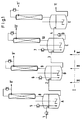
In Fig. 1 und 2 sind beispielhaft verschiedene Ausführungsformen der Erfindung gezeigt. Im Text angegebene Nummern und Buchstaben beziehen sich auf diese Abbildungen.Various embodiments of the invention are shown by way of example in FIGS. 1 and 2. Numbers and letters in the text refer to these illustrations.
Die am ersten Rührbehälter A einzudosierende Reaktionskomponente der Formel (III) kann gegebenenfalls in einem vorgeschalteten Erhitzerelement auf die vorgesehene Reaktionstemperatur vorgeheizt werden. So kann in flüssiger Form an beliebiger Stelle, z.B. über Leitung (1) in Fig. 1 oder 2 oder durch ein Rohr (5) in Fig. 1 in die Flüssigphase unterhalb des Rührers eingebracht werden.The reaction component of the formula (III) to be metered into the first stirred tank A can optionally be preheated to the intended reaction temperature in an upstream heating element. So in liquid form at any point, e.g. can be introduced via line (1) in Fig. 1 or 2 or through a tube (5) in Fig. 1 in the liquid phase below the stirrer.
Die aus dem jeweiligen Rührbehälter zu entnehmende Flüssigphase kann an geeigneter Stelle des Behälters z.B. im oberen Drittel oder über einen gegebenenfalls beheizbaren, in der Höhe verstellbaren Siphon (2) und (3) in Fig. 1 und 2 entnommen und in den jeweils folgenden Rührbehälter B bzw. C geleitet werden. Dabei soll ein vorgegebener Füllstand im jeweiligen Behälter realisiert werden. Die für den kontinuierlichen Betrieb von Kesselkaskaden zu verwendenden Techniken sind Stand der Technik und dem Fachmann bekannt.The liquid phase to be removed from the respective stirred tank can be removed at a suitable point in the tank, for example in the upper third or via an optionally heatable, height-adjustable siphon (2) and (3) in FIGS. 1 and 2 and into the respective subsequent stirred tank B. or C are passed. A predetermined fill level should be realized in the respective container. The techniques to be used for the continuous operation of boiler cascades are state of the art and known to the person skilled in the art.
Das organische Carbonat der Formel (II) wird gasförmig durch den kontinuierlich laufenden Flüssigkeitsstrom I entweder im Querstrom (Kreuzstrom) (Fig. 1) oder bevorzugt im Gegenstrom (Fig. 2) geschickt.The organic carbonate of the formula (II) is sent in gaseous form through the continuously running liquid stream I either in the crossflow (crossflow) (FIG. 1) or preferably in the counterflow (FIG. 2).
Querstrom (Kreuzstrom) bedeutet dabei, daß die Edukte der Formel (II) jeweils an jedem Rührbehälter A, B, und C eindosiert werden ((5), (6), (7) in Fig. 1) und jeweils am Kopf eines jeden Rührbehälters ((8), (9), (10) in Fig. 1) wieder entnommen werden, d.h. die Edukte der Formel (II) durchströmen die Rührbehälter quer zur Flußrichtung der Flüssigphase. Dabei kann die Gesamtmenge der einzudosierenden Edukte der Formel (II) beliebig auf die einzelnen Rührbehälter aufgeteilt werden,Cross flow (cross flow) means that the starting materials of the formula (II) are metered into each stirred tank A, B, and C ((5), (6), (7) in FIG. 1) and in each case at the top of each Stirring container ((8), (9), (10) in Fig. 1) can be removed again, ie the starting materials of the formula (II) flow through the stirred vessels transversely to the direction of flow of the liquid phase. The total amount of the starting materials of the formula (II) to be metered in can be divided as desired between the individual stirred tanks,
Die bevorzugt zu verwendende Gegenstromfahrweise (Fig. 2) bedeutet, daß die Edukte der Formel (II) am letzten Rührbehälter (C in Fig. 2) über Leitung (5) eindosiert, kontinuierlich gegen die vom ersten zum letzten Rührbehälter laufende Flüssigphase geführt und am Kopf des ersten Rührbehälters (A in Fig. 2) über Leitung (8) entnommen werden.The preferred countercurrent procedure (FIG. 2) means that the starting materials of the formula (II) are metered into the last stirred tank (C in FIG. 2) via line (5), continuously conducted against the liquid phase running from the first to the last stirred tank and on The head of the first stirred tank (A in Fig. 2) can be removed via line (8).
Die Edukte der Formel (II) können in beiden Fällen entweder flüssig eindosiert und durch die vorhandene Flüssigphase verdampft werden oder bevorzugt in einem vorgeschalteten Apparat verdampft und gasförmig in den jeweiligen Rührbehälter eingebracht werden, Die Eindosierung kann dabei entweder in die Flüssigphase oder in den überstehenden Gasraum erfolgen. Die Durchmischung der Gas- und Flüssigphase wird durch geeignete, oben genannte, dem Fachmann bekannte Rührorgane erreichte Bei der Verwendung von Begasungsrührern mit Hohlwelle kann die Eindosierung der Gasphase auch direkt in die Hohlwelle des Begasungsrührers erfolgen.In both cases, the starting materials of the formula (II) can either be metered in in liquid form and evaporated through the liquid phase present, or preferably evaporated in an upstream apparatus and introduced into the respective stirred tank in gaseous form. The metering in can be carried out either in the liquid phase or in the protruding gas space respectively. The mixing the gas and liquid phase is achieved by suitable stirrers known to the person skilled in the art. When using gassing stirrers with a hollow shaft, the gas phase can also be metered directly into the hollow shaft of the gassing stirrer.
Die am Kopf des jeweiligen Rührbehälters zu entnehmenden Reaktionsprodukte der Formel (IV) können z.B. gasförmig über (8'), (9'), (10') und (11') abgenommen werden.The reaction products of the formula (IV) to be taken off at the top of the respective stirred tank can, for example, can be removed in gaseous form via (8 '), (9'), (10 ') and (11').
Dabei ist es gegebenenfalls von Vorteil, durch geeignete Dephlegmierung oder durch eine aufgesetzte Kolonne höhersiedende Reaktionsbestandteile, z.B. Produkte der Formel (I) oder Edukte der Formel (III), vorher abzutrennen und in den jeweiligen Rührbehälter zurückzuführen. Die Produkte der Formel (IV) können so beispielsweise ohne Kondensation in eine geeignete Trennvorrichtung eingebracht werden. Dies kann im Falle der Umsetzung von Dimethylcarbonat mit Phenol eine Druckdestillationskolonne zur Trennung des anfallenden Dimethylcarbonat-Methanol-Gemisches sein, wie sie dem Fachmann bekannt ist. Das dabei anfallende Dimethylcarbonat, das gegebenenfalls noch geringe Mengen Methanol enthält, kann als Edukt der Formel (II) in den Umesterungsprozeß zurückgeführt werden.In this case, it may be advantageous, by suitable dephlegmation or by an attached column, to boil higher reaction components, e.g. Products of the formula (I) or starting materials of the formula (III), to be separated off beforehand and returned to the respective stirred tank. The products of the formula (IV) can thus be introduced into a suitable separation device, for example without condensation. In the case of the reaction of dimethyl carbonate with phenol, this can be a pressure distillation column for separating the resulting dimethyl carbonate-methanol mixture, as is known to the person skilled in the art. The resulting dimethyl carbonate, which may still contain small amounts of methanol, can be recycled into the transesterification process as a starting material of the formula (II).
Ebenso ist es möglich, die Produkte der Formel (IV), gegebenenfalls nach Abtrennung von höhersiedenden Reaktionsbestandteilen, wie oben beschrieben, abzunehmen und zu kondensieren. Eine Reinigung und Auftrennung des Produktstroms kann dann in geeigneter, dem Fachmann bekannter Art und Weise, durchgeführt werden.It is also possible to remove and condense the products of the formula (IV), if appropriate after separating off higher-boiling reaction components, as described above. The product stream can then be cleaned and separated in a suitable manner known to the person skilled in the art.
Der am letzten Reaktor C flüssig zu entnehmende Produktstrom kann gegebenenfalls in einem nachgeschalteten Abtriebsteil D von leichtsiedenden Bestandteilen, z.B. den Edukten der Formel (II) oder den Produkten der Formel (IV), abgetrennt werden, wobei diese in den letzten Rührbehälter C zurückgeführt werden. Der flüssig entnommene Produktstrom kann nach üblichen Methoden, z.B. durch Destillation aufgearbeitet und gereinigt werden.The product stream to be withdrawn in liquid form at the last reactor C can optionally contain low-boiling constituents, e.g. the starting materials of the formula (II) or the products of the formula (IV) are separated off, these being returned to the last stirred tank C. The liquid product stream withdrawn can be made by conventional methods, e.g. processed and purified by distillation.
In einer weiteren Verfahrensweise kann der flüssig zu entnehmende Produktstrom in 1 bis 5, bevorzugt 1 bis 3 nachgeschaltete gegebenenfalls gerührte oder mit Inertgas begaste Verweilzeitbehälter E geleitet werden, wobei dort weitere Reaktionen im Sinne von Gleichung 2 und/oder Gleichung 3 ablaufen können. In diesem Falle werden das aromatische Carbonat der Formel (I) bei (11) und in E entstandene flüchtige Reaktionsprodukte bei (11') entnommen.In a further procedure, the product stream to be withdrawn in liquid form can be passed into 1 to 5, preferably 1 to 3, downstream, optionally stirred or gassed with inert gas residence time containers E, where further reactions in the sense of
Der jeweils letzte Verweilzeitbehälter E kann gegebenenfalls ein nachgeschaltetes Abtriebsteil besitzen, mit dem leichtsiedende Produkte der Formel (IV) und/oder nicht umgesetzte Edukte der Formel (III) ganz oder teilweise in diesen Verweilzeitbehälter E zurückgeführt werden. Ebenso ist es gegegebenfalls von Vorteil, die am Kopf des ersten Verweilzeitbehälters E z.B. über (11') zu entnehmenden flüchtigen Reaktionsprodukte der Formel (IV) durch ein dort aufgesetztes Verstärker- oder Dephelegmatorteil von höhersiedenden Produkten der Formel (I) oder Edukten der Formel (III) abzutrennen und diese in E zurückzuführen.The last residence time container E may optionally have a downstream stripping section with which low-boiling products of the formula (IV) and / or unreacted starting materials of the formula (III) are wholly or partly returned to this residence time container E. It is also advantageous if necessary to remove the volatile reaction products of the formula (IV) at the top of the first residence time container E, for example via (11 '), by means of an amplifier or dephelegmator part placed there to separate from higher-boiling products of the formula (I) or starting materials of the formula (III) and to recycle them in E.
In einer weiteren Variante ist der Verweilzeitbehälter E in Form einer Destillationsapparatur ausgebildet, die im Sinne einer "Reaktionsdestillation" betrieben wird, das heißt, daß simultan zur ablaufenden Reaktion eine Destillation der beteiligten Stoffe durchgeführt wird.In a further variant, the residence time container E is designed in the form of a distillation apparatus which is operated in the sense of a "reaction distillation", that is to say that the substances involved are distilled simultaneously with the reaction taking place.
Die für eine "Reaktionsdestillation" im Sinne der Erfindung wesentlichen Merkmale sind die folgenden: Das noch nicht umgesetzte Alkylarylcarbonat-Zwischenprodukt wird durch einen speziell gewählten Temperaturgradienten in der Destillationsapparatur weitgehend daran gehindert, den Reaktionsteil des Reaktors nach oben oder nach unten zu verlassen. Die leichtflüchtigen Reaktionsprodukte der Formel (IV) werden am Kopf der Kolonne, das schwerflüchtige Reaktionsprodukt, hier das Diarylcarbonat, wird am Fuß der Kolonne entnommen. Gegebenenfalls vorhandenes, überschüssiges Phenol kann entweder zusammen mit den Diarylcarbonat-Endprodukten am Fuß der Destillationsapparatur oder zusammen mit den Leichtsiederprodukten am Kopf der Apparatur entnommen werden.The essential features for a "reaction distillation" in the sense of the invention are the following: The unreacted alkylaryl carbonate intermediate is largely prevented by a specially selected temperature gradient in the distillation apparatus from leaving the reaction part of the reactor upwards or downwards. The volatile reaction products of the formula (IV) are taken off at the top of the column, the low-volatility reaction product, here the diaryl carbonate, is taken off at the bottom of the column. Any excess phenol which may be present can be taken off either at the bottom of the distillation apparatus together with the end diaryl carbonate products or at the top of the apparatus together with the low boiler products.
Der als "Reaktionskolonne" bezeichnete Reaktor besteht aus einem kolonnenartigen Rohr dem ein Temperaturprofil angelegt wird, das von oben nach unten gesehen ansteigend einen Temperaturbereich von 60 bis 320°C, bevorzugt 65 bis 305°C und besonders bevorzugt von 65 bis 250°C, umfaßt. Zur Einstellung der Temperaturgradienten in den einzelnen Abschnitten des kolonnenartigen Reaktors können diese Abschnitte mit einer Isolierung bzw. einer Thermostatisierung versehen werden. Die Thermostatisierung kann hierbei je nach Bedarf eine Heizung oder eine Kühlung darstellen. Die Reaktionskolonne kann in verschiedenen Abschnitten ihrer Gesamtlänge, entsprechend den Gas- und Flüssigbelastungen und den benötigten Verweilzeiten aufgeweitet oder verengt sein.The reactor referred to as the "reaction column" consists of a column-like tube to which a temperature profile is applied which, viewed from top to bottom, increases in temperature from 60 to 320 ° C., preferably 65 to 305 ° C. and particularly preferably from 65 to 250 ° C. includes. For setting the temperature gradients in the In individual sections of the column-like reactor, these sections can be provided with insulation or thermostatting. Thermostatization can represent heating or cooling as required. The reaction column can be widened or narrowed in various sections of its total length, in accordance with the gas and liquid loads and the required residence times.
Für den mittleren Teil der Reaktionskolonne, den Reaktionsbereich, sind feste Einbauten bevorzugt, für die Teile, in denen Trennungen stattfinden, dagegen Füllkörper und feste Packungen.Solid internals are preferred for the middle part of the reaction column, the reaction region, while packing and solid packings are preferred for the parts in which separations take place.
Am unteren Ende der Reaktionskolonne sind ein oder mehrere, gegebenenfalls durch adiabatisch isolierte Kolonnenteile getrennte Verdampfer angeordnet. Diese Verdampfer können innerhalb oder bevorzugt außerhalb der Kolonne angeordnet sein. In einer technischen Ausführung werden in der Technik übliche Apparate wie Umlaufverdampfer, Fallfilmverdampfer und Wendelrohrverdampfer verwendet.At the lower end of the reaction column, one or more evaporators, optionally separated by adiabatically isolated column parts, are arranged. These evaporators can be arranged inside or preferably outside the column. In a technical version, equipment customary in the art such as circulation evaporators, falling film evaporators and spiral tube evaporators are used.
Oberhalb der Verdampferzone, in dem als "Reaktionszone" bezeichneten mittleren Bereich, werden bevorzugt feste Einbauten und besonders bevorzugt solche mit großem Flüssigkeits-Holp Up benutzt, beispielsweise Glockenböden mit hohen Überlaufwehren, wie in DE 2 503 195 beschrieben. Die theroretische Bodenzahl in diesem Bereich beträgt 1 bis 50, bevorzugt 2 bis 25 und besonders 2 bis 15.Above the evaporator zone, in the middle area referred to as the "reaction zone", solid internals and particularly preferably those with a large liquid holp up are used, for example bell bottoms with high overflow weirs, as described in
Wiederum oberhalb dieses Bereichs ist die Kolonne mit weiteren, im besonderen Maße für destillative Stofftrennungen geeigneten Füllkörpern oder Einbauten ausgestattet. Am oberen Ende der Kolonne ist bevorzugt ein Verstärkerteil angeordnet, mit dem ein gezielter Rücklauf der Kolonne einstellbar ist.Again above this range, the column is equipped with further packing elements or internals which are particularly suitable for separations by distillation. At the upper end of the column there is preferably an amplifier section with which a targeted reflux of the column can be set.
Die Reaktionskolonne wird so betrieben, daß man oberhalb der "Reaktionszone" den aus der Rührbehälterkaskade flüssig entnommenen Produktstrom flüssig eindosiert. Dieser Strom durchläuft die "Reaktionszone" und wird dort teilweise in Diarylcarbonat verwandelt, und die noch nicht umgesetzten Reaktanden werden mit Hilfe der beschriebenen Verdampfer gasförmig zurück in die Reaktionszone und die oberen Teile der Kolonne transportiert. Diese kondensieren dort und setzen sich erneut zum Diarylcarbonat-Endprodukt um. Das Diarylcarbonat-Endprodukt wird als höchst siedende Reaktionskomponente im Sumpfbereich der Kolonne angereichert und dort zusammen mit gegebenenfalls homogen gelöstem Katalysator und geringen Mengen Alkylphenylcarbonat und aromatischer Hydroxyverbindung ausgespeist.The reaction column is operated in such a way that the product stream liquid taken from the cascade of stirred tanks is metered in liquid above the "reaction zone". This stream passes through the "reaction zone" and is partially converted into diaryl carbonate there, and the unreacted reactants are transported in gaseous form back into the reaction zone and the upper parts of the column using the evaporators described. These condense there and react again to the final diaryl carbonate product. The final diaryl carbonate product is enriched as the highest-boiling reaction component in the bottom region of the column and is fed out there together with optionally homogeneously dissolved catalyst and small amounts of alkylphenyl carbonate and aromatic hydroxy compound.
Die leichtflüchtigen Reaktionsprodukte der Formel (IV) werden am Kopf der Kolonne entnommen. Die im Überschuß vorhandenen oder nicht umgesetzten Phenole der Formel (III) können entweder am Fuß der Kolonne zusammen mit dem Diarylcarbonat-Endprodukt der Formel (I) oder in einer bevorzugten Fahrweise zusammen mit den Leichtsiederprodukten am Kopf der Kolonne ausgespeist werden.The volatile reaction products of the formula (IV) are removed at the top of the column. The phenols of the formula (III) which are present in excess or unreacted can either be fed out at the bottom of the column together with the final diaryl carbonate product of the formula (I) or, in a preferred procedure, together with the low boiler products at the top of the column.
Der am letzten Reaktor C oder Verweilzeitbehälter E flüssig entnommene Produktstrom, der die Produkte der Formel (I) enthält, kann in einer weiteren besonderen Ausführung der Erfindung, nach Zwischenlagerung in geeigneten Behältern, anstelle des Edukts der Formel (III) zurück in den 1. Reaktorbehälter A gespeist werden. Dies ist gegebenenfalls auch mehrfach möglich, wobei die Zuspeisung des zweiten Edukts der Formel (II) gegebenenfalls auch unterbleiben kann. Zur kontinuierlichen Durchführung einer solchen Fahrweise sind entweder mindestens zwei Lagerbehälter oder ein Lagerbehälter mit mindestens zwei Kammern notwendig, wobei in der 1. Kammer das Produkt aus der laufenden Umsetzung eingespeist und aus der 2. Kammer das Edukt für die laufende Umsetzung entnommen wird Wenn eine Kammer geleert bzw. eine Kammer gefüllt ist, wird die 2. Kammer zur Aufnahme des Produktes aus der Kesselkaskade und die 1. Kammer zur Einspeisung des Eduktes in die Kesselkaskade benutzt.In a further special embodiment of the invention, after intermediate storage in suitable containers, the product stream which is taken off in liquid form at the last reactor C or residence time container E and which contains the products of the formula (I) can be returned to FIG. 1 instead of the starting material of the formula (III). Reactor vessel A are fed. This may also be possible several times, the addition of the second starting material of the formula (II) possibly also being omitted. To carry out such a procedure continuously, either at least two storage containers or a storage container with at least two chambers are necessary, the product from the current reaction being fed into the 1st chamber and the educt for the current reaction being taken from the 2nd chamber if one chamber is emptied or a chamber is filled, the second chamber is used to take up the product from the boiler cascade and the first chamber is used to feed the educt into the boiler cascade.
In einer weiteren Verfahrensweise kann zusätzlich zu den Edukten ein unter den Reaktionsbedingungen inertes Lösungsmittel oder Gas an beliebiger Stelle der Apparatur eingespeist werden. Solche inerte Lösungsmittel sind beispielsweise Kohlenwasserstoffe, wie Hexan, Heptan, i-Octan, Cyclohexan, Methylcyclohexan, Toluol, Xylole, Chlorbenzole, Tetralin, Dekalin etc. Als inerte Gase kommen beispielsweise Kohlendioxid, Stickstoff, Edelgase etc. in Frage.In a further procedure, in addition to the starting materials, a solvent or gas which is inert under the reaction conditions can be fed in at any point in the apparatus. Such inert solvents are, for example, hydrocarbons, such as hexane, heptane, i-octane, cyclohexane, methylcyclohexane, toluene, xylenes, chlorobenzenes, tetralin, decalin etc. As inert gases, for example carbon dioxide, nitrogen, noble gases etc. are suitable.
Die zu verwendenden und als solche bekannten Umesterungskatalysatoren werden bevorzugt zusammen mit den flüssig zu dosierenden Edukten der Formel (III) in gelöster oder suspendierter Form in die Rührbehälter eingebracht. Alternativ kann der Katalysator auch separat oder gelöst bzw. suspendiert in einer geringen Menge des Eduktes der Formel (III) oder in einem systemfremden, geeigneten, inerten Lösungsmittel s.o. eindosiert werden. Im Falle der Verwendung heterogener Katalysatoren können diese auch im Rührbehälter direkt ortsfest eingesetzt werden.The transesterification catalysts to be used and known as such are preferably introduced into the stirred tank together with the starting materials of the formula (III) to be metered in liquid in dissolved or suspended form. Alternatively, the catalyst can also be separately or dissolved or suspended in a small amount of the starting material of the formula (III) or in a non-systemic, suitable, inert solvent see above. be dosed. If heterogeneous catalysts are used, they can also be used directly in a fixed position in the stirred tank.
Durch geeignete Filtriervorrichtung muß dabei das Austragen der Katalysatoren verhindert werden.The discharge of the catalysts must be prevented by a suitable filtering device.
Wichtig ist, daß mindestens in 2 Rührbehältern ein Katalysator vorhanden ist.It is important that a catalyst is present in at least 2 stirred tanks.
Im Falle der Verwendung von nicht ortsfesten Katalysatoren ist es möglich, die Katalysatoren nach teilweiser oder vollständiger Abtrennung von den Produkten oder Edukten wieder wie oben beschrieben in den Reaktionsprozeß zurückzuführen, wobei gegebenenfalls ein der desaktivierten Katalysatormenge entsprechender Anteil des Katalysators abgetrennt und durch frischen Katalysator ersetzt wird.If non-stationary catalysts are used, it is possible, after partial or complete separation from the products or starting materials, to return the catalysts to the reaction process as described above, where appropriate a portion of the catalyst corresponding to the deactivated amount of catalyst is separated off and replaced by fresh catalyst .
Das erfindungsgemäße Verfahren wird bei Temperaturen in der Flüssigphase von 80 bis 350°C, bevorzugt bei 100 bis 250°C und besonders bevorzugt bei Temperaturen von 120 bis 240°C durchgeführt. Dabei soll die Flüssigphasentemperatur in den Rührbehältern nicht über der Verdampfungstemperatur der eingesetzten phenolischen Verbindung der Formel (III) liegen. Es kann deshalb von Vorteil sein, die erfindungsgemäße Umesterung im Bereich der Rührbehälter nicht nur bei Normaldruck, sondern auch bei erhöhtem oder erniedrigtem Druck im Bereich von 10 mbar bis 20 bar durchzuführen. Ein bevorzugter Druckbereich liegt zwischen 0,05 und 15 bar, ein besonders bevorzugter Druckbereich liegt zwischen 0,08 und 10 bar.The process according to the invention is carried out at temperatures in the liquid phase of 80 to 350 ° C., preferably at 100 to 250 ° C. and particularly preferably at temperatures of 120 up to 240 ° C. The liquid phase temperature in the stirred tanks should not be above the evaporation temperature of the phenolic compound of the formula (III) used. It can therefore be advantageous to carry out the transesterification according to the invention in the region of the stirred tank not only at normal pressure, but also at elevated or reduced pressure in the range from 10 mbar to 20 bar. A preferred pressure range is between 0.05 and 15 bar, a particularly preferred pressure range is between 0.08 and 10 bar.
Katalysatoren, die für das erfindungsgemäße Verfahren in Frage kommen und die für alle Phasen des erfindungsgemäßen Verfahrens gleich sein können, sind in der Literatur bekannt. Solche Katalysatoren sind beispielsweise Hydride, Oxide, Hydroxide, Alkoholate, Amide oder Salze von (Erd)Alkalimetallen, wie Lithium, Natrium, Kalium, Rubidium, Cäsium, Magnesium und Calcium, bevorzugt von Lithium, Natrium, Kalium, Magnesium und Calcium, besonders bevorzugt von Lithium, Natrium und Kalium (US-3 642 858, US-3 803 201, EP 1082). Für den Fall des Einsatzes der Alkoholate können diese erfindungsgemäß auch in situ durch Einsatz der elementaren Alkalimetalle und des erfindungsgemäßen umzusetzenden Alkohols gebildet werden. Salze der (Erd)Alkalimetalle können solche von organischen oder anorganischen Säuren sein, wie von Essigsäure, Propionsäure, Buttersäure, Benzoesäure, Stearinsäure, Kohlensäure (Carbonate oder Hydrogencarbonate), von Salzsäure, Bromwasserstoff- oder Iodwasserstoffsäure, Salpetersäure, Schwefelsäure, Fluorwasserstoffsäure, Phosphorsäure, Blausäure, Rhodanwasserstoff, Borsäure, Zinnsäure, C1-C4-Stannonsäuren oder Antimonsäuren. In bevorzugter Weise kommen als Verbindungen der (Erd)Alkalimetalle die Oxide, Hydroxide, Alkoholate, Acetate, Propionate, Benzoate, Carbonate und Hydrogencarbonate in Frage, in besonders bevorzugter Weise werden Hydroxide, Alkoholate, Acetate, Benzoate oder Carbonate eingesetzt.Catalysts which are suitable for the process according to the invention and which can be the same for all phases of the process according to the invention are known in the literature. Such catalysts are, for example, hydrides, oxides, hydroxides, alcoholates, amides or salts of (earth) alkali metals, such as lithium, sodium, potassium, rubidium, cesium, magnesium and calcium, preferably of lithium, sodium, potassium, magnesium and calcium, particularly preferred of lithium, sodium and potassium (U.S. 3,642,858, U.S. 3,803,201, EP 1082). If the alcoholates are used, they can also be formed according to the invention in situ by using the elemental alkali metals and the alcohol to be reacted according to the invention. Salts of the (earth) alkali metals can be those of organic or inorganic acids, such as acetic acid, propionic acid, butyric acid, benzoic acid, stearic acid, carbonic acid (carbonates or hydrogen carbonates), hydrochloric acid, hydrobromic acid or Hydroiodic acid, nitric acid, sulfuric acid, hydrofluoric acid, phosphoric acid, hydrocyanic acid, rhodanhydrogen, boric acid, tin acid, C 1 -C 4 stannic acids or antimonic acids. The oxides, hydroxides, alcoholates, acetates, propionates, benzoates, carbonates and hydrogen carbonates are preferred as compounds of the (earth) alkali metals, and hydroxides, alcoholates, acetates, benzoates or carbonates are used in a particularly preferred manner.
Solche (Erd)Alkalimetallverbindungen (gegebenenfalls in situ gebildet aus den freien Alkalimetallen) werden in Mengen von 0,001 bis 2 Gew.-%, bevorzugt 0,005 bis 0,9 Gew.-%, besonders bevorzugt 0,01 bis 0,5 Gew.-%, bezogen auf das umzusetzende Reaktionsgemisch, eingesetzt.Such (earth) alkali metal compounds (optionally formed in situ from the free alkali metals) are used in amounts of 0.001 to 2% by weight, preferably 0.005 to 0.9% by weight, particularly preferably 0.01 to 0.5% by weight. %, based on the reaction mixture to be used.
Weitere erfindungsgemäß einsetzbare Katalysatoren sind Lewis-saure Metallverbindungen wie AlX3, TiX3, UX4, TiX4, VOX3, VX5, ZnX2, FeX3 und SnX4, worin X für Halogen, Acetoxy oder Aryloxy steht (DE-OS 2 528 412, 2 552 907), beispielsweise Titantetrachlorid, Titantetraphenoxid, Titantetraethoxid, Titantetraisopropylat, Titantetradodecylat, Zinntetraisooctylat und Aluminiumtriisopropylat, weiterhin zinnorganische Verbindungen der allgemeinen Formel (R4)4-x-Sn(Y)x, in der Y für einen Rest OCOR5, OH oder OR5 steht, wobei R5 C1-C12-Alkyl, C6-C12-Aryl oder C7-C13-Alkylaryl bedeutet und R4 unabhängig von R5 den Bedeutungsumfang von R5 annehmen kann und x eine ganze Zahl von 1 bis 3 bedeutet, Dialkylzinnverbindungen mit 1 bis 12 C-Atomen im Alkylrest oder Bis(trialkylzinn)verbindungen, beispielsweise Trimethylzinnacetat, Triethylzinnbenzoat, Tributylzinnacetat, Triphenylzinnacetat, Dibutylzinndiacetat, Dibutylzinndilaurat, Dioctylzinndilaurat, Dibutylzinnadipinat, Dibutyldimethoxyzinn, Dimethylzinnglykolat, Dibutyldiethoxyzinn, Triethylzinnhydroxid, Hexaethylstannoxan, Hexabutylstannoxan, Dibutylzinnoxid, Dioctylzinnoxid, Butylzinntriisooctylat, Octylzinntriisooctylat, Butylstannonsäure und Octylstannonsäure in Mengen von 0,001 bis 20 Gew,-% (EP 879, EP 880, EP 39 452, DE-OS 3 445 555, JP 79/62 023), polymere Zinnverbindungen der Formel -[-R4,R5Sn-O-]-, beispielsweise Poly[oxy(dibutylstannylen)], Poly[oxy(dioctylstannylen)], Poly[oxy(butylphenylstannylen)] und Poly[oxy(diphenylstannylen)] (DE-OS 3 445 552), polymere Hydroxystannoxane der Formel -[R4Sn(OH)-O-]-, beispielsweise Poly(ethylhydroxystannoxan), Poly(butylhydroxystannoxan), Poly(octylhydroxystannoxan), Poly(undecylhydroxystannoxan) und Poly(dodecylhydroxystannoxan) in Mengen von 0,001 bis 20 Gew.-%, bevorzugt von 0,005 bis 5 Gew.-%, bezogen auf Kohlensäurediester (DE 4 006 520). Weitere erfindungsgemäß einsetzbare Zinnverbindungen sind Sn(II)oxid oder besitzen die Formel
X1-Sn(R4)2-O-Sn(R4)2-X2 (IX)
worin
- X1 und X2
- unabhängig voneinander OH, SCN, OR4, OCOR4 oder Halogen und
- R4
- Alkyl, Aryl bedeutet (EP 338 760).
X 1 -Sn (R 4 ) 2 -O-Sn (R 4 ) 2 -X 2 (IX)
wherein
- X 1 and X 2
- independently of one another OH, SCN, OR 4 , OCOR 4 or halogen and
- R 4
- Alkyl, aryl means (EP 338 760).
Als weitere erfindungsgemäß einsetzbare Katalysatoren kommen Bleiverbindungen, gegebenenfalls zusammen mit Triorganophosphanen, einer Chelatverbindung oder einem Alkalimetallhalogenid, beispielsweise Pb(OH)2·2PbCO, Pb(OCO-CH3)2, Pb(OCO-CH3)2·2LiCl, Pb(OCO-CH3)2·2PPh3 in Mengen von 0,001 bis 1, bevorzugt von 0,005 bis 0,25 mol pro Mol Carbonat (JP 57/176 932, JP 01/093 580), andere Blei(II)- und Blei(IV)-verbindungen, wie PbO, PbO2, Mennige, Plumbite (PbO2 2-) und Plumbate (PbO3 2-) (JP 01/093 560), Eisen(III)acetat (JP 61/172 852), weiterhin Kupfersalze und/oder Metallkomplexe, beispielsweise von Alkalimetallen, Zink, Titan und Eisen (JP 89/005 588), Kombinationen aus Lewis-Säuren und Protonensäuren (DE-OS 3 445 553) oder Elementverbindungen von Sc, Cr, Mo, W, Mn, Au, Ga, In, Bi, Te und Lanthaniden (EP 338 760) in Frage.Other catalysts which can be used according to the invention are lead compounds, optionally together with triorganophosphanes, a chelate compound or an alkali metal halide, for example Pb (OH) 2 .2PbCO, Pb (OCO-CH 3 ) 2 , Pb (OCO-CH 3 ) 2 .2LiCl, Pb ( OCO-CH 3 ) 2 .2PPh 3 in amounts of 0.001 to 1, preferably 0.005 to 0.25 mol per mole of carbonate (JP 57/176 932, JP 01/093 580), other lead (II) and lead ( IV) compounds, such as PbO, PbO 2 , red lead, plumbite (PbO 2 2- ) and plumbate (PbO 3 2- ) (JP 01/093 560), iron (III) acetate (JP 61/172 852) Copper salts and / or metal complexes, for example of alkali metals, zinc, titanium and iron (JP 89/005 588), combinations of Lewis acids and protonic acids (
Weiterhin sind im erfindungsgemäßen Verfahren heterogene Katalysatorsysteme einsetzbar. Solche sind beispielsweise Mischoxide aus Silicium und Titan, die durch gemeinsame Hydrolyse von Silicium- und Titanhalogeniden herstellbar sind (JP 54/125 617) und Titandioxide mit hoher BET-Oberfläche > 20 m2/g (DE-OS 4 036 594).In addition, heterogeneous catalyst systems can be used in the process according to the invention. Such are, for example, mixed oxides of silicon and titanium, which can be produced by joint hydrolysis of silicon and titanium halides (JP 54/125 617) and titanium dioxides with a high BET surface area> 20 m 2 / g (
Bevorzugt im erfindungsgemäßen Verfahren einsetzbare Katalysatoren sind Zinn-, Titan- und Zirkoniumverbindungen und die obengenannten Alkali- und Erdalkaliverbindungen, besonders bevorzugt einsetzbare Katalysatoren sind Organozinnverbindungen und Titantetraalkoholate und -phenolate.Catalysts which can preferably be used in the process according to the invention are tin, titanium and zirconium compounds and the abovementioned alkali and alkaline earth compounds, particularly preferably catalysts which can be used are organotin compounds and titanium tetraalcoholates and phenolates.
Die einzusetzenden Katalysatormengen betragen 0,01 bis 10 mol-%, bevorzugt 0,05 bis 5 mol-% und besonders bevorzugt 0,01 bis 2 mol-%, bezogen auf eingesetzte Phenol- oder Alkylarylcarbonatkomponente, und können sich teilweise von den in der Literatur genannten Mengen unterscheiden.The amounts of catalyst to be used are 0.01 to 10 mol%, preferably 0.05 to 5 mol% and particularly preferably 0.01 to 2 mol%, based on the phenol or alkylaryl carbonate component used, and can differ in part from those in the Differentiate the amounts mentioned in the literature.
Die folgenden Beispiele sollen die vorliegende Erfindung konkret erläutern, wobei sie nicht auf diese Beispiele beschränkt sein soll.The following examples are intended to explain the present invention in concrete terms, but should not be restricted to these examples.
Drei mit Öl beheizte Doppelmantelgefäße mit jeweils 1 l Innenvolumen wurden so hintereinandergeschaltet, daß die Flüssigphase am Boden des ersten Reaktors zudosiert, aus dem ersten Reaktor über einen, in der Höhe verstellbaren, Siphon entnommen und am Boden des nächsten Reaktors wieder eingespeist wurde. Am dritten Reaktor wurde die Flüssigphase über einen Siphon entnommen. Die Gasphase wurde in den dritten Reaktor eingespeist, am Kopf wieder entnommen und in den vorgeschalteten Reaktor weitergeleitet. Die Vermischung von Gas- und Flüssigphase erfolgte in den einzelnen Reaktoren durch schnell laufende Begasungsrührer (1500 U/min). Die Entnahme der Gasphase erfolgte am Kopf des ersten Reaktors über eine 30 cm lange mit Raschigringen gefüllte Kolonne mit aufgesetztem Kolonnenkopf, der die Einstellung eines Rücklaufs auf die Kolonne erlaubte. Die Dosier- und Verbindungsleitungen waren mit Heizbändern so thermostatisiert, daß sowohl die Kristallisation der Flüssigphase als auch die Kondensation der Gasphase in diesen Leitungen verhindert wurde.Three oil-heated double jacket vessels, each with an internal volume of 1 l, were connected in series so that the liquid phase was metered in at the bottom of the first reactor, removed from the first reactor via a height-adjustable siphon and fed in again at the bottom of the next reactor. The liquid phase was removed from the third reactor via a siphon. The gas phase was fed into the third reactor, removed again at the top and passed on to the upstream reactor. The gas and liquid phases were mixed in the individual reactors using fast-running gassing stirrers (1500 rpm). The gas phase was withdrawn at the top of the first reactor via a 30 cm long column filled with Raschig rings with an attached column top, which allowed a reflux to be set on the column. The metering and connecting lines were thermostatted with heating tapes in such a way that both the crystallization of the liquid phase and the condensation of the gas phase in these lines were prevented.
Die Reaktoren wurden mit jeweils 600 ml Phenol gefüllt und die Reaktormäntel mit Öl auf 180°C thermostatisiert. Über eine beheizte Pumpe wurden 510 g/h einer Mischung aus 98,6 Gew.-% Phenol und 1,4 Gew.-% Octylstannonsäure (Flüssigphase) in den ersten Reaktor kontinuierlich dosiert und gleichzeitig 500 g/h Dimethylcarbonat, das kontinuierlich in einem elektrisch beheizten Rohr verdampft wurde, in den dritten Reaktor. Nach 5 h befand sich die Reaktion im stationären Gleichgewicht, d.h. die Zusammensetzung der Flüssigphasen in den einzelnen Reaktoren und die Produktzusammensetzung änderte sich nicht mehr. Am dritten Reaktor wurden dann kontinuierlich 579 g/h Produktgemisch mit 60 g/h Methylphenylcarbonat und 12 g/h Diphenylcarbonat entnommen. Der Rest zu 100 % waren Phenol, wenig Dimethylcarbonat und Katalysator.The reactors were each filled with 600 ml of phenol and the reactor jackets thermostatted to 180 ° C. with oil. 510 g / h of a mixture of 98.6% by weight of phenol and 1.4% by weight of octylstannonic acid (liquid phase) were fed continuously into the first reactor via a heated pump metered and at the same time 500 g / h of dimethyl carbonate, which was continuously evaporated in an electrically heated tube, in the third reactor. After 5 hours the reaction was in steady state equilibrium, ie the composition of the liquid phases in the individual reactors and the product composition did not change anymore. 579 g / h of product mixture with 60 g / h of methylphenyl carbonate and 12 g / h of diphenyl carbonate were then removed continuously from the third reactor. The rest 100% were phenol, little dimethyl carbonate and catalyst.
Am Kopf der am ersten Reaktor aufgesetzten Kolonne wurden 453 g/h Produktgemisch aus Methanol und Dimethylcarbonat entnommen. Daraus ergibt sich eine Raum-Zeit-Ausbeute für die Methylphenyl- und Diphenylcarbonatbildung von 24 g x 1-1h-1. Die Selektivität bezüglich der Bildung aromatischer Carbonate war > 99,9 %.At the top of the column attached to the first reactor, 453 g / h of product mixture of methanol and dimethyl carbonate were removed. This results in a space-time yield for the methylphenyl and diphenyl carbonate formation of 24 gx 1 -1 h -1 . The selectivity for the formation of aromatic carbonates was> 99.9%.
In der in Beispiel 1 beschriebenen Apparatur (Fig. 2 ohne E) und unter den dort angegebenen Reaktionsbedingungen wurden 1,45 kg/h eines Gemisches aus 97,8 Gew.-% Phenol und 2,2 Gew.-% Titantetraphenolat am Boden des 1. Reaktors und 1,35 kg/h Dimethylcarbonat am Kopf des dritten Reaktors kontinuierlich eingespeist. Nach ca. 5 h befand sich die Reaktion im Gleichgewicht. Am Ende des 3. Reaktors wurden kontinuierlich 1,51 kg/h flüssiges Produktgemisch mit 175 g/h Methylphenylcarbonat und 42 g/h Diphenylcarbonat und am Kopf der am ersten Reaktor aufgesetzten Kolonne 1,27 kg/h Gemisch aus Methanol und Dimethylcarbonat entnommen. Das entspricht einer Raum-Zeit-Ausbeute für die Methylphenyl- und Diphenylcarbonatbildung von 72 g x 1-1h-1. Die Selektivität bezgl. Bildung von aromatischen Carbonaten war > 99 %.In the apparatus described in Example 1 (FIG. 2 without E) and under the reaction conditions specified there, 1.45 kg / h of a mixture of 97.8% by weight of phenol and 2.2% by weight of titanium tetraphenolate were at the bottom of the 1. reactor and 1.35 kg / h of dimethyl carbonate at the top of the third reactor continuously fed. After about 5 hours the reaction was in equilibrium. At the end of the 3rd reactor, 1.51 kg / h of liquid product mixture containing 175 g / h of methylphenyl carbonate were added continuously and 42 g / h of diphenyl carbonate and 1.27 kg / h of mixture of methanol and dimethyl carbonate at the top of the column attached to the first reactor. This corresponds to a space-time yield for the formation of methylphenyl and diphenyl carbonate of 72 gx 1 -1 h -1 . The selectivity with regard to the formation of aromatic carbonates was> 99%.
Das Beispiel 2 wurde in der dort angegebenen Apparatur und mit den dort angegebenen Reaktionsbedingungen und Eduktströmen wiederholt. Darüber hinaus wurde die am dritten Reaktor entnommene Flüssigphase kontinuierlich in einen weiteren Rührbehälter (E in Fig. 2) mit 2 l Innenvolumen und aufgesetzter Kolonne geleitet und dort kontinuierlich wieder über einen höhenverstellbaren und beheizten Siphon entnommen. Dieser Rührbehälter wurde auf 175°C Innentemperatur erhitzt. Nach 7 h befand sich die Reaktion im Gleichgewicht. Am 4. Rührbehälter wurden kontinuierlich 1,47 kg/h Flüssigphase mit 17,5 g/h Methylphenyl- und 157 g/h Diphenylcarbonat entnommen. Das entspricht einer Raum-Zeit-Ausbeute der Diphenylcarbonat- und Methylphenylcarbonatbildung von 35 g x l-1h-1. Die Selektivität der Bildung der aromatischen Carbonate war > 99 %.Example 2 was repeated in the apparatus specified there and with the reaction conditions and educt streams specified therein. In addition, the liquid phase removed from the third reactor was continuously passed into a further stirred tank (E in FIG. 2) with a 2 l internal volume and attached column, where it was continuously removed again via a height-adjustable and heated siphon. This stirred tank was heated to an internal temperature of 175 ° C. After 7 hours the reaction was in equilibrium. 1.47 kg / h of liquid phase with 17.5 g / h of methylphenyl carbonate and 157 g / h of diphenyl carbonate were continuously removed from the 4th stirred tank. This corresponds to a space-time yield of the diphenyl carbonate and methylphenyl carbonate formation of 35 gxl -1 h -1 . The selectivity of aromatic carbonate formation was> 99%.
Ein beheizter Rührbehälter mit 2 l Innenvolumen, der mit einer 1,2 m langen, mit 6 mm Glasringen gefüllten Kolonne ausgestattet war, wurde mit 942 g Phenol und 21 g Titantetraphenolat gefüllt. Der Inhalt des Behälters wurde auf 175°C vorgeheizt und Dimethylcarbonat so zugetropft, daß die Innentemperatur zwischen 160 und 165°C gehalten wurde. Innerhalb von 4 h wurden 155 g Dimethylcarbonat zugetropft und gleichzeitig am Kopf der Kolonne ein Gemisch aus 17,4 g Methanol und 15,5 g Dimethylcarbonat entnommen. Das Sumpfprodukt hatte nach dieser Zeit die Zusammensetzung 854 g Phenol, 117 g Methylphenylcarbonat, 26 g Diphenylcarbonat, 89 g Dimethylcarbonat und 3 g Nebenprodukte. Daraus ergab sich eine Raum-Zeit-Ausbeute für Bildung der aromatischen Carbonate von ca. 18 g.l-1h-1. Die Selektivität der Arylcarbonatbildung betrug ca. 89 %.A heated stirred vessel with an internal volume of 2 l, which was equipped with a column 1.2 m long and filled with 6 mm glass rings, was filled with 942 g phenol and 21 g titanium tetraphenolate. The contents of the container were preheated to 175 ° C and dimethyl carbonate was added dropwise so that the internal temperature was kept between 160 and 165 ° C. 155 g of dimethyl carbonate were added dropwise over the course of 4 h and at the same time a mixture of 17.4 g of methanol and 15.5 g of dimethyl carbonate was removed from the top of the column. After this time, the bottom product had the composition 854 g phenol, 117 g methylphenyl carbonate, 26 g diphenyl carbonate, 89 g dimethyl carbonate and 3 g by-products. This resulted in a space-time yield for the formation of the aromatic carbonates of approx. 18 gl -1 h -1 . The selectivity of aryl carbonate formation was approximately 89%.
Claims (10)
- Process for producing an aromatic carbonate of the formula
R1-O-CO-O-R2 (I)
in whichR2 is phenyl or naphthyl and phenyl or naphthyl mono- to trisubstituted by straight-chain or branched C1-C4-alkyl, straight-chain or branched C1-C4-alkoxy, cyano and/or halogen, andR1 assumes, independently of R2, the scope of meaning of R2 or straight-chain or branched C1-C6-alkyl,by catalysed reaction of, in each case, 0.1-10 mol, preferably 0.2-5 mol, particularly preferably 0.5-3 mol of an organic carbonate containing at least one aliphatic ester group of the formula
R1-OCOO-R3 (II)
in whichR3 is straight-chain or branched C1-C6-alkyl andR1 has the above scope of meaning,with 1 mol of a phenolic compound of the formula
R2-OX (III)
in whichR2 has the above scope of meaning andX represents hydrogen or -CO-O-C1-C6-alkyl containing a straight-chain or branched alkyl group,in the presence of a transesterification catalyst, known per se at, 80-350°C and 10 mbar to 20 bar, characterized in that the reaction is carried out in at least two stirred containers connected one behind the other in accordance with the principle of cross flow or counter flow in such a way that the phenolic compound of the formula (III) is metered in liquid form into the first stirred container and the organic carbonate of the formula (II) in cross-flow mode into each of the stirred containers and in counter-flow mode into the last stirred container and the reaction product of the formula (I) is removed in liquid form at the last stirred container, if necessary after traversing a dwell-time section, and the products of the formula
R3-OX (IV)
in whichR3 and X have the specified meaningare removed in cross-flow mode at the head of each stirred container and in counter-flow mode at the head of the first stirred container. - Process according to Claim 1, characterized in that the reaction is carried out in at least two stirred containers connected one behind the other in such a way that the organic carbonate of the formula (II) is metered into the last stirred container and the aromatic carbonate of the formula (I) is removed in liquid form at the last stirred container and the product of the formula (IV) is removed at the head of the first stirred container.
- Process according to Claim 1, characterized in that the reaction is carried out in 2 to 10, preferably in 3 to 10, particularly preferably in 3 to 8, stirred containers connected one behind the other.
- Process according to Claim 1, characterized in that the process is carried out at 100-250°C, preferably at 120 to 240°C.
- Process according to Claim 1, characterized in that the process is carried out in the pressure range from 0.05 to 15 bar, preferably 0.08 to 10 bar.
- Process according to Claim 1, characterized in that a phenolic compound of the formula
R12-OH (V)
is used,
in whichR12 is phenyl or phenyl monosubstituted by C1-C4-alkyl, C1-C4-alkoxy or chlorine. - Process according to Claim 6, characterized in that unsubstituted phenol is used.
- Process according to Claim 1, characterized in that a symmetrical dialkyl carbonate of the formula
R3-O-CO-O-R3 (VI)
in whichR3 is straight-chain or branched C1-C6-alkyl, is used as organic carbonate containing at least one aliphatic ester group. - Process according to Claim 8, characterized in that dimethyl carbonate is used.
- Process according to Claim 1, characterized in that the organic carbonate (II) is used in a mixture with 0-5 % by weight, preferably 0.1-3 % by weight, particularly preferably 0.15-2 % by weight, based on the weight of (II), of basic alcohol R3-OH.
Applications Claiming Priority (2)
| Application Number | Priority Date | Filing Date | Title |
|---|---|---|---|
| DE4301899A DE4301899A1 (en) | 1993-01-25 | 1993-01-25 | Process for the continuous production of aryl carbonates |
| DE4301899 | 1993-01-25 |
Publications (2)
| Publication Number | Publication Date |
|---|---|
| EP0608710A1 EP0608710A1 (en) | 1994-08-03 |
| EP0608710B1 true EP0608710B1 (en) | 1997-07-30 |
Family
ID=6478855
Family Applications (1)
| Application Number | Title | Priority Date | Filing Date |
|---|---|---|---|
| EP94100367A Expired - Lifetime EP0608710B1 (en) | 1993-01-25 | 1994-01-12 | Process for the continuous preparation of aryle carbonates |
Country Status (5)
| Country | Link |
|---|---|
| US (1) | US5463102A (en) |
| EP (1) | EP0608710B1 (en) |
| JP (1) | JP3528006B2 (en) |
| DE (2) | DE4301899A1 (en) |
| ES (1) | ES2105352T3 (en) |
Families Citing this family (6)
| Publication number | Priority date | Publication date | Assignee | Title |
|---|---|---|---|---|
| JP2003026633A (en) * | 2001-05-02 | 2003-01-29 | Sumitomo Chem Co Ltd | Method for producing methacrylic ester |
| US7919644B2 (en) | 2004-06-17 | 2011-04-05 | Asahi Kasei Chemicals Corporation | Process for producing an aromatic carbonate |
| TWI321561B (en) | 2004-12-21 | 2010-03-11 | Asahi Kasei Chemicals Corp | Method for producing aromatic carbonate |
| US7288668B2 (en) * | 2005-11-17 | 2007-10-30 | Catalytic Distillation Technologies | Process for making diaryl carbonate |
| DE102007044033A1 (en) * | 2007-09-14 | 2009-03-19 | Bayer Materialscience Ag | Process for the preparation of diaryl or alkylaryl carbonates from dialkyl carbonates |
| KR101411016B1 (en) * | 2011-12-27 | 2014-06-23 | 제일모직주식회사 | Catalyst, method for preparing the same amd method for preparing aromatic carbonate from dialkyl carbonate using the catalyst |
Family Cites Families (17)
| Publication number | Priority date | Publication date | Assignee | Title |
|---|---|---|---|---|
| US3642858A (en) * | 1969-02-12 | 1972-02-15 | Dow Chemical Co | Carbonate synthesis from alkylene carbonates |
| US4182726A (en) * | 1974-06-25 | 1980-01-08 | Snamprogetti, S.P.A. | Process for the preparation of aromatic carbonates |
| IT1025961B (en) * | 1974-11-25 | 1978-08-30 | Snam Progetti | PROCESS FOR THE PREPARATION OF AROMATIC CARBONATES |
| US4079038A (en) * | 1976-03-05 | 1978-03-14 | Alza Corporation | Poly(carbonates) |
| US4403056A (en) * | 1980-02-11 | 1983-09-06 | Stauffer Chemical Company | Carbonate esters, carbonate ester compositions, and plasticized compositions |
| DE3017419A1 (en) * | 1980-05-07 | 1981-11-12 | Bayer Ag, 5090 Leverkusen | METHOD FOR PRODUCING AROMATIC POLYCARBONATES |
| US4612386A (en) * | 1980-09-16 | 1986-09-16 | The Dow Chemical Company | Process for making esters |
| US4410464A (en) * | 1982-03-15 | 1983-10-18 | General Electric Company | Diaryl carbonate process |
| US4552704A (en) * | 1983-12-27 | 1985-11-12 | General Electric Company | Process for the production of aromatic carbonates |
| US5276134A (en) * | 1987-03-18 | 1994-01-04 | The Dow Chemical Company | Process for the preparation of phenyl carbonates or polycarbonates |
| US4973728A (en) * | 1987-08-12 | 1990-11-27 | The Dow Chemical Company | Preparation of aromatic carbonates |
| EP0461274B1 (en) * | 1989-12-28 | 1994-06-15 | Asahi Kasei Kogyo Kabushiki Kaisha | Process for continuously producing aromatic carbonate |
| GB2255972A (en) * | 1991-04-12 | 1992-11-25 | Davy Res & Dev Ltd | Production of diaryl carbonates. |
| US5218078A (en) * | 1991-07-15 | 1993-06-08 | The Dow Chemical Company | Process for preparing halogenated polycarbonate from emulsified reaction mixture |
| DE4138755A1 (en) * | 1991-11-26 | 1993-05-27 | Bayer Ag | METHOD FOR PRODUCING DIALKYL CARBONATES |
| DE4207853A1 (en) * | 1992-03-12 | 1993-09-16 | Bayer Ag | METHOD FOR PRODUCING AROMATIC CARBONATES |
| DE4226755A1 (en) * | 1992-08-13 | 1994-02-17 | Bayer Ag | Process for the continuous production of diaryl carbonates from dialkyl carbonates |
-
1993
- 1993-01-25 DE DE4301899A patent/DE4301899A1/en not_active Withdrawn
-
1994
- 1994-01-12 EP EP94100367A patent/EP0608710B1/en not_active Expired - Lifetime
- 1994-01-12 ES ES94100367T patent/ES2105352T3/en not_active Expired - Lifetime
- 1994-01-12 DE DE59403488T patent/DE59403488D1/en not_active Expired - Fee Related
- 1994-01-18 US US08/182,867 patent/US5463102A/en not_active Expired - Lifetime
- 1994-01-19 JP JP01775094A patent/JP3528006B2/en not_active Expired - Fee Related
Also Published As
| Publication number | Publication date |
|---|---|
| US5463102A (en) | 1995-10-31 |
| JP3528006B2 (en) | 2004-05-17 |
| EP0608710A1 (en) | 1994-08-03 |
| ES2105352T3 (en) | 1997-10-16 |
| JPH06234707A (en) | 1994-08-23 |
| DE59403488D1 (en) | 1997-09-04 |
| DE4301899A1 (en) | 1994-07-28 |
Similar Documents
| Publication | Publication Date | Title |
|---|---|---|
| EP0582930B1 (en) | Process for the preparation of diarylcarbonates | |
| EP0582931B1 (en) | Process for the continuous preparation of diarylcarbonates from dialkylcarbonates | |
| EP0614877B1 (en) | Process for the continuous preparation of aryle carbonates | |
| EP2239249B1 (en) | Method for producing diarylcarbonates or arylalkylcarbonates from dialkylcarbonates | |
| EP0572870B1 (en) | Process for the production of organic carbonates with at least one aromatic ester group | |
| EP2062868B1 (en) | Process for purifying diaryl carbonates | |
| EP2322261B1 (en) | Method for cleaning dialkyl carbonates | |
| EP2135857B1 (en) | Method for manufacturing diaryl carbonates from dialkyl carbonates | |
| EP1216982B1 (en) | Process for the preparation of diaryl esters of carbonic acid | |
| EP2036880A2 (en) | Method for producing diarylcarbonates or arylalkylcarbonates from dialkylcarbonates | |
| EP1216981B1 (en) | Continuous process for the preparation of diaryl esters of carbonic acid | |
| EP2457891B1 (en) | Method for manufacturing diaryl carbonates from dialkyl carbonates | |
| EP0608710B1 (en) | Process for the continuous preparation of aryle carbonates | |
| EP2650278A1 (en) | Method for manufacturing diaryl carbonates from dialkyl carbonates | |
| EP3140278B1 (en) | Method for manufacturing diaryl carbonates | |
| DE4312037A1 (en) | Process for cleaving polycarbonates | |
| EP1995233A2 (en) | Method for producing diarylcarbonates or arylalkylcarbonates from dialkylcarbonates | |
| EP3140279B1 (en) | Process for producing diarylcarbonates | |
| DE4316428A1 (en) | Process for the continuous production of aryl carbonates | |
| EP0739896A2 (en) | Process for the preparation of 6-oxo-(6H)-dibenz-(c,e)(1,2)-oxaphosphorines | |
| EP0075145A1 (en) | Process for the continuous preparation of chloroformic-acid alkyl esters |
Legal Events
| Date | Code | Title | Description |
|---|---|---|---|
| PUAI | Public reference made under article 153(3) epc to a published international application that has entered the european phase |
Free format text: ORIGINAL CODE: 0009012 |
|
| AK | Designated contracting states |
Kind code of ref document: A1 Designated state(s): BE DE ES FR GB IT NL |
|
| 17P | Request for examination filed |
Effective date: 19950111 |
|
| 17Q | First examination report despatched |
Effective date: 19960322 |
|
| GRAG | Despatch of communication of intention to grant |
Free format text: ORIGINAL CODE: EPIDOS AGRA |
|
| GRAH | Despatch of communication of intention to grant a patent |
Free format text: ORIGINAL CODE: EPIDOS IGRA |
|
| GRAH | Despatch of communication of intention to grant a patent |
Free format text: ORIGINAL CODE: EPIDOS IGRA |
|
| GRAA | (expected) grant |
Free format text: ORIGINAL CODE: 0009210 |
|
| AK | Designated contracting states |
Kind code of ref document: B1 Designated state(s): BE DE ES FR GB IT NL |
|
| PG25 | Lapsed in a contracting state [announced via postgrant information from national office to epo] |
Ref country code: NL Free format text: LAPSE BECAUSE OF FAILURE TO SUBMIT A TRANSLATION OF THE DESCRIPTION OR TO PAY THE FEE WITHIN THE PRESCRIBED TIME-LIMIT Effective date: 19970730 |
|
| GBT | Gb: translation of ep patent filed (gb section 77(6)(a)/1977) |
Effective date: 19970805 |
|
| REF | Corresponds to: |
Ref document number: 59403488 Country of ref document: DE Date of ref document: 19970904 |
|
| ITF | It: translation for a ep patent filed |
Owner name: SOCIETA' ITALIANA BREVETTI S.P.A. |
|
| REG | Reference to a national code |
Ref country code: ES Ref legal event code: FG2A Ref document number: 2105352 Country of ref document: ES Kind code of ref document: T3 |
|
| ET | Fr: translation filed | ||
| NLV1 | Nl: lapsed or annulled due to failure to fulfill the requirements of art. 29p and 29m of the patents act | ||
| PLBE | No opposition filed within time limit |
Free format text: ORIGINAL CODE: 0009261 |
|
| STAA | Information on the status of an ep patent application or granted ep patent |
Free format text: STATUS: NO OPPOSITION FILED WITHIN TIME LIMIT |
|
| 26N | No opposition filed | ||
| REG | Reference to a national code |
Ref country code: GB Ref legal event code: IF02 |
|
| PGFP | Annual fee paid to national office [announced via postgrant information from national office to epo] |
Ref country code: GB Payment date: 20020116 Year of fee payment: 9 |
|
| PGFP | Annual fee paid to national office [announced via postgrant information from national office to epo] |
Ref country code: FR Payment date: 20020123 Year of fee payment: 9 |
|
| PG25 | Lapsed in a contracting state [announced via postgrant information from national office to epo] |
Ref country code: GB Free format text: LAPSE BECAUSE OF NON-PAYMENT OF DUE FEES Effective date: 20030112 |
|
| GBPC | Gb: european patent ceased through non-payment of renewal fee | ||
| PG25 | Lapsed in a contracting state [announced via postgrant information from national office to epo] |
Ref country code: FR Free format text: LAPSE BECAUSE OF NON-PAYMENT OF DUE FEES Effective date: 20030930 |
|
| REG | Reference to a national code |
Ref country code: FR Ref legal event code: ST |
|
| PGFP | Annual fee paid to national office [announced via postgrant information from national office to epo] |
Ref country code: DE Payment date: 20031213 Year of fee payment: 11 |
|
| PGFP | Annual fee paid to national office [announced via postgrant information from national office to epo] |
Ref country code: BE Payment date: 20040128 Year of fee payment: 11 |
|
| PG25 | Lapsed in a contracting state [announced via postgrant information from national office to epo] |
Ref country code: IT Free format text: LAPSE BECAUSE OF NON-PAYMENT OF DUE FEES;WARNING: LAPSES OF ITALIAN PATENTS WITH EFFECTIVE DATE BEFORE 2007 MAY HAVE OCCURRED AT ANY TIME BEFORE 2007. THE CORRECT EFFECTIVE DATE MAY BE DIFFERENT FROM THE ONE RECORDED. Effective date: 20050112 |
|
| PG25 | Lapsed in a contracting state [announced via postgrant information from national office to epo] |
Ref country code: BE Free format text: LAPSE BECAUSE OF NON-PAYMENT OF DUE FEES Effective date: 20050131 |
|
| BERE | Be: lapsed |
Owner name: *BAYER A.G. Effective date: 20050131 |
|
| PG25 | Lapsed in a contracting state [announced via postgrant information from national office to epo] |
Ref country code: DE Free format text: LAPSE BECAUSE OF NON-PAYMENT OF DUE FEES Effective date: 20050802 |
|
| BERE | Be: lapsed |
Owner name: *BAYER A.G. Effective date: 20050131 |
|
| PGFP | Annual fee paid to national office [announced via postgrant information from national office to epo] |
Ref country code: ES Payment date: 20100128 Year of fee payment: 17 |
|
| REG | Reference to a national code |
Ref country code: ES Ref legal event code: FD2A Effective date: 20120220 |
|
| PG25 | Lapsed in a contracting state [announced via postgrant information from national office to epo] |
Ref country code: ES Free format text: LAPSE BECAUSE OF NON-PAYMENT OF DUE FEES Effective date: 20110113 |