EP1995233A2 - Method for producing diarylcarbonates or arylalkylcarbonates from dialkylcarbonates - Google Patents
Method for producing diarylcarbonates or arylalkylcarbonates from dialkylcarbonates Download PDFInfo
- Publication number
- EP1995233A2 EP1995233A2 EP08008796A EP08008796A EP1995233A2 EP 1995233 A2 EP1995233 A2 EP 1995233A2 EP 08008796 A EP08008796 A EP 08008796A EP 08008796 A EP08008796 A EP 08008796A EP 1995233 A2 EP1995233 A2 EP 1995233A2
- Authority
- EP
- European Patent Office
- Prior art keywords
- column
- carbonate
- transesterification
- reaction zone
- condenser
- Prior art date
- Legal status (The legal status is an assumption and is not a legal conclusion. Google has not performed a legal analysis and makes no representation as to the accuracy of the status listed.)
- Withdrawn
Links
Images


Classifications
-
- C—CHEMISTRY; METALLURGY
- C07—ORGANIC CHEMISTRY
- C07C—ACYCLIC OR CARBOCYCLIC COMPOUNDS
- C07C68/00—Preparation of esters of carbonic or haloformic acids
- C07C68/06—Preparation of esters of carbonic or haloformic acids from organic carbonates
-
- B—PERFORMING OPERATIONS; TRANSPORTING
- B01—PHYSICAL OR CHEMICAL PROCESSES OR APPARATUS IN GENERAL
- B01D—SEPARATION
- B01D3/00—Distillation or related exchange processes in which liquids are contacted with gaseous media, e.g. stripping
- B01D3/009—Distillation or related exchange processes in which liquids are contacted with gaseous media, e.g. stripping in combination with chemical reactions
-
- C—CHEMISTRY; METALLURGY
- C07—ORGANIC CHEMISTRY
- C07C—ACYCLIC OR CARBOCYCLIC COMPOUNDS
- C07C68/00—Preparation of esters of carbonic or haloformic acids
- C07C68/08—Purification; Separation; Stabilisation
-
- C—CHEMISTRY; METALLURGY
- C07—ORGANIC CHEMISTRY
- C07C—ACYCLIC OR CARBOCYCLIC COMPOUNDS
- C07C69/00—Esters of carboxylic acids; Esters of carbonic or haloformic acids
- C07C69/96—Esters of carbonic or haloformic acids
-
- Y—GENERAL TAGGING OF NEW TECHNOLOGICAL DEVELOPMENTS; GENERAL TAGGING OF CROSS-SECTIONAL TECHNOLOGIES SPANNING OVER SEVERAL SECTIONS OF THE IPC; TECHNICAL SUBJECTS COVERED BY FORMER USPC CROSS-REFERENCE ART COLLECTIONS [XRACs] AND DIGESTS
- Y02—TECHNOLOGIES OR APPLICATIONS FOR MITIGATION OR ADAPTATION AGAINST CLIMATE CHANGE
- Y02P—CLIMATE CHANGE MITIGATION TECHNOLOGIES IN THE PRODUCTION OR PROCESSING OF GOODS
- Y02P20/00—Technologies relating to chemical industry
- Y02P20/10—Process efficiency
-
- Y—GENERAL TAGGING OF NEW TECHNOLOGICAL DEVELOPMENTS; GENERAL TAGGING OF CROSS-SECTIONAL TECHNOLOGIES SPANNING OVER SEVERAL SECTIONS OF THE IPC; TECHNICAL SUBJECTS COVERED BY FORMER USPC CROSS-REFERENCE ART COLLECTIONS [XRACs] AND DIGESTS
- Y10—TECHNICAL SUBJECTS COVERED BY FORMER USPC
- Y10S—TECHNICAL SUBJECTS COVERED BY FORMER USPC CROSS-REFERENCE ART COLLECTIONS [XRACs] AND DIGESTS
- Y10S203/00—Distillation: processes, separatory
Definitions
- the invention relates to a process for the preparation of diaryl carbonates and / or alkylaryl carbonates from dialkyl carbonates and aromatic hydroxy compounds using at least one reaction column with one or more intermediate condensers to improve the heat integration.
- the transesterification is also preferably carried out continuously in the sense of a countercurrent transesterification in one or more reaction columns.
- EP-A 0 461 274 describes a continuous transesterification process for the preparation of aromatic carbonates in one or more series-connected multistage columns, wherein dialkyl or alkylaryl are reacted with phenols and at the top of the columns the volatile products, namely the reaction alcohols and dialkyl and at the bottom of the columns, the high-boiling products , such as diaryl carbonates are removed.
- special process measures which permit a more advantageous transesterification by adapting the apparatuses and procedures to the specific problems of this transesterification mentioned above are not described.
- the person skilled in the art receives no indication as to whether the column used for transesterification is preferably carried out with or without a reinforcing part.
- the vapor mixture taken off at the top of the column essentially contains the excess used in the reaction Dialkyl carbonate and the corresponding resulting in the reaction of alcohol and the condensation of the mixture is carried out at a temperature which is below the vaporization temperature of the dialkyl carbonate at the pressure present in the reaction, with the result that the heat of condensation compared to the temperature in the reaction zone can be dissipated only at a low temperature level. If the transesterification column is carried out without a reinforcing part, the vapor mixture taken off at the top of the column and thus also the distillate of the column contains not insignificant amounts of the aromatic hydroxy compounds used for the reaction and optionally also heavier components.
- DE-A 42 26 756 describes a two-step process for the preparation of diaryl carbonates in which, in a first step, an aromatic hydroxy compound is reacted with a dialkyl carbonate in a countercurrent transesterification using a countercurrent transesterification column which can be carried out both with and without a reinforcing part.
- the temperature level in the condensation is relatively low, so that the resulting heat of condensation can not be used economically for operating other process sections.
- the distillate additionally contains a high proportion of the aromatic hydroxy compound in addition to the dialkyl carbonate and the alcohol formed upon reaction. This results in the recovery of the dialkyl carbonate to an elevated temperature level in the region of the column bottom, which makes it difficult to supply energy at this point.
- DE-A 42 26 755 describes a process for the preparation of diaryl carbonates in two energetically and materially coupled reaction columns, wherein in the first stage an aromatic hydroxy compounds and a dialkyl carbonate are reacted and the resulting alkylaryl carbonate in the second stage either by transesterification with the aromatic hydroxy compound or by Disproportionation is converted to diaryl carbonate.
- the problem here is, however, that the reaction conditions for the formation of the alkylaryl or diaryl carbonate can not be optimally selected by the material and energetic integration of the process, since these are determined by the present in both steps and almost identical pressure. The method described therefore provides no advantages in terms of energy integration.
- the EP-A 781 760 describes a continuous process for preparing aromatic carbonates by reacting a dialkyl carbonate with an aromatic hydroxy compound in the presence of a catalyst, continuously removing the aromatic carbonate resulting from the reaction, the alcoholic by-products, the dialkyl carbonate and the hydroxy aromatic compound, the dialkyl carbonate and the hydroxy aromatic compound again be attributed to the reaction.
- the method steps described are effective with respect to the reaction in terms of a high space-time yield and the workup in the sense of the most efficient separation sequence, but the process shows no possibilities for an energetic integration of the reaction and work-up steps.
- WO-A 2006/001256 describes a process in which an aromatic hydroxy compound is reacted with a dialkyl carbonate in the presence of a catalyst and a technical device suitable for this purpose. Again, no clues are given for energetic integration.
- WO-A 2004/016577 describes a process for the preparation of aromatic carbonates from dialkyl carbonate and an aromatic hydroxy compound in the presence of a catalyst in a plurality of separate and series reaction zones of a reactor arrangement, wherein the resulting heat of condensation in the condensation of the vapor stream of the last reaction zone for heating the liquid stream introduced into the first reaction zone is used.
- a disadvantage of this method is the complex reactor arrangement.
- the energy integration of this process is in need of improvement.
- the object on which the invention was based was therefore to provide a process for the preparation of aromatic carbonates, ie diaryl and / or alkylaryl carbonates, preferably diaryl carbonates, in which over known processes a Energy integration is possible in an efficient manner or an improved energy integration can be achieved.
- This object has been achieved according to the invention by the appropriate use of one or more intermediate condensers in a process for the preparation of aromatic carbonates, i. Diaryl and / or alkylaryl, from dialkyl carbonates and aromatic hydroxy compounds energy integration can be significantly improved with simple process control.
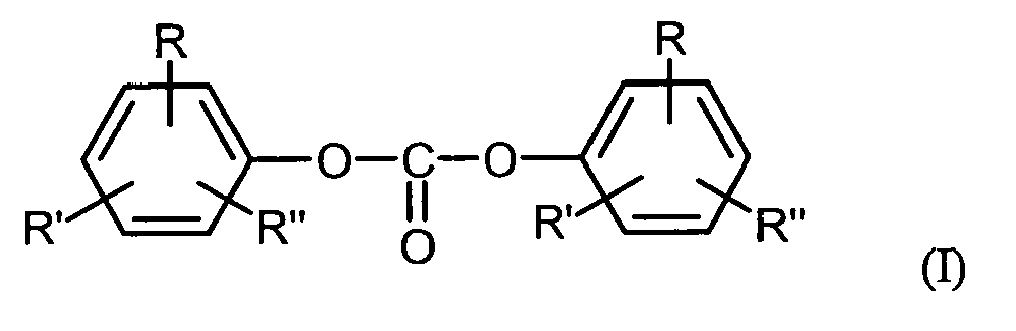
- Diaryl carbonates prepared in the context of the invention are preferably those of the general formula (I) where R, R 'and R "independently of one another are H, linear or branched, optionally substituted C 1 -C 34 -alkyl, preferably C 1 -C 6 -alkyl, particularly preferably C 1 -C 4 -alkyl, C 1 -C 34 Alkoxy, preferably C 1 -C 6 -alkoxy, more preferably C 1 -C 4 -alkoxy, C 5 -C 34 -cycloalkyl, C 7 -C 34 -alkylaryl, C 6 -C 34 -aryl or a halogen radical represent a chlorine radical and R, R 'and R "may be the same or different on both sides of the formula (I).
- R can also be -COO-R '", where R"' is H, optionally branched C 1 -C 34 -alkyl, preferably C 1 -C 6 -alkyl, particularly preferably C 1 -C 4 -alkyl, C 1 -C 34 -alkoxy, preferably C 1 -C 6 -alkoxy, particularly preferably C 1 -C 4 -alkoxy, C 5 -C 34 -cycloalkyl, C 7 -C 34 Alkylaryl or C 6 -C 34 -aryl.
- R, R 'and R are preferably the same on both sides of the formula (I).
- R, R' and R" are very particularly preferably H.
- Diarylcarbonates of the general formula (I) are, for example: diphenyl carbonate, methylphenylphenyl carbonates and di (methylphenyl) carbonates, also as a mixture, where the position of the methyl group on the phenyl rings may be arbitrary, and dimethylphenyl-phenyl-carbonates and di ( dimethylphenyl) carbonates, also as a mixture, wherein the position of the methyl groups on the phenyl rings may be arbitrary, chlorophenyl-phenyl-carbonates and di (chlorophenyl) carbonates, wherein the position of the methyl group on the phenyl rings may be arbitrary, 4-ethylphenyl phenyl carbonate, di- (4-ethylphenyl) carbonate, 4-n-propylphenyl phenyl carbonate, di- (4-n-propylphenyl) carbonate, 4-iso-propylphenyl phenyl carbonate, di- ( 4-iso-
- Preferred diaryl carbonates are: diphenyl carbonate, 4-tert-butylphenyl phenyl carbonate, di (4-tert-butylphenyl) carbonate, biphenyl-4-yl phenyl carbonate, di (biphenyl-4-yl) carbonate, 4- (1-methyl-1-phenylethyl) -phenyl-phenyl-carbonate and di- [4- (1-methyl-1-phenylethyl) -phenyl] -carbonate.
- diphenyl carbonate is particularly preferred.
- Dialkyl carbonates preferably used in the context of the invention are those of the formula (II) wherein R 1 and R 2 independently of one another are linear or branched, optionally substituted C 1 -C 34 -alkyl, preferably C 1 -C 6 -alkyl, more preferably C 1 -C 4 -alkyl.
- R 1 and R 2 may be the same or different.
- R 1 and R 2 are the same.
- C 1 -C 4 -alkyl is, for example, methyl, ethyl, n-propyl, isopropyl, n-butyl, sec-butyl, tert-butyl, C 1 -C 6 -alkyl, moreover, for example for n-pentyl, 1-methylbutyl, 2-methylbutyl, 3-methylbutyl, neo-pentyl, 1-ethylpropyl, cyclohexyl, cyclopentyl, n-hexyl, 1,1-dimethylpropyl, 1,2-dimethylpropyl, 1-methylpentyl, 2 Methylpentyl, 3-methylpentyl, 4-methylpentyl, 1,1-dimethylbutyl, 1,2-dimethylbutyl, 1,3-dimethylbutyl, 2,2-dimethylbutyl, 2,3-dimethylbutyl, 3,3-di
- Alkylene radicals in the corresponding hydroxyalkyl or aralkyl or alkylaryl radicals are, for example, the alkylene radicals corresponding to the preceding alkyl radicals.
- Aryl represents a carbocyclic aromatic radical having 6 to 34 skeleton carbon atoms.
- aromatic part of an arylalkyl radical also called aralkyl radical
- aryl constituents of more complex groups such as e.g. Arylcarbonyl.
- Arylalkyl or aralkyl each independently a straight-chain, cyclic, branched or unbranched alkyl radical as defined above which is simple, can be substituted by aryl radicals as defined above, multiply or fully.
- Preferred dialkyl carbonates are dimethyl carbonate, diethyl carbonate, di (n-propyl) carbonate, di (iso-propyl) carbonate, di (n-butyl) carbonate, di (sec-butyl) carbonate, di (tert-butyl) carbonate or dihexyl carbonate. Particularly preferred are dimethyl carbonate or diethyl carbonate. Very particular preference is given to dimethyl carbonate.
- suitable aromatic hydroxy compounds are preferably those of the general formula (III) wherein R, R 'and R "independently of one another may have the meaning given for the general formula (I).
- aromatic hydroxy compounds are, for example: phenol, o-, m- or p-cresol, also as a mixture of cresols, dimethylphenol, also as a mixture, wherein the position of the methyl groups on the phenol ring may be arbitrary, e.g.
- Preferred diaryl compounds are phenol, 4-tert-butylphenol, biphenyl-4-ol and 4- (1-methyl-1-phenylethyl) phenol.
- Particularly preferred is phenol.
- Alkylaryl carbonates prepared in the context of the invention are preferably those of the general formula (IV) wherein R, R 'and R "for the general formula (I) and R 1 may have the meaning given for the general formula (II).
- Preferred alkylaryl carbonates are methyl phenyl carbonate, ethyl phenyl carbonate, propyl phenyl carbonate, butyl phenyl carbonate and hexyl phenyl carbonate, methyl (o-cresyl) carbonate, methyl (p-cresyl) carbonate , Ethyl (o-cresyl) carbonate, ethyl (p-cresyl) carbonate, methyl or ethyl (p-chlorophenyl) carbonate.
- Particularly preferred alkylaryl carbonates are methyl phenyl carbonate and ethyl phenyl carbonate. Very particular preference is given to methylphenyl carbonate.
- dialkyl carbonates which are suitable for the process according to the invention and the aromatic hydroxy compounds are known to the person skilled in the art and are commercially available or can be prepared by processes which are likewise known to the person skilled in the art.
- the aromatic hydroxy compound (s) and the dialkyl carbonate (s) are preferably in a molar ratio of from 1: 0.1 to 1:10, more preferably from 1: 0.2 to 1: 5, most preferably from 1: 0.5 to 1: 3 used.
- the stated molar ratio does not take into account the recycling of aromatic hydroxy compound or dialkyl carbonate into the transesterification column via one or more top condenser (s) (see under (b)) or one or more optional bottom evaporators.
- the process according to the invention is carried out in a transesterification column.
- the liquid stream taken off at the bottom of this transesterification column can, if appropriate after concentration, be subjected to disproportionation, further transesterification and / or purification in one or more further steps.
- individual or all such further steps can take place in one or more further columns.
- transesterification column or optionally second or further column (s) known to those skilled in columns come into question.
- these are, for example, distillation or rectification columns, preferably reactive distillation columns or reactive rectification columns.
- the transesterification column contains at least one enrichment section in the upper part of the column and at least one reaction zone below the reinforcement section, which has at least two sections, wherein at least one reinforcement section of the transesterification column is equipped with at least one intermediate condenser.
- Each of the two sections independently of one another preferably has 0 to 20, preferably 0.1 to 20 theoretical steps each.
- the intermediate capacitor is preferably mounted between the two sections of the reinforcing member. In this case, the reinforcing member is divided into upper and lower reinforcing members.
- the transesterification column is preferably operated in countercurrent, wherein preferably in at least one reaction zone of this column, the aromatic hydroxy compound is passed liquid from the head to the bottom and the dialkyl carbonate is passed in gaseous form this liquid stream.
- the transesterification column is preferably operated so that at least one reaction zone, preferably in the upper third of the reaction zone, one or more, the aromatic hydroxy compound and optionally dissolved transesterification catalyst containing streams, preferably with the prevailing at this point of the column temperature, liquid or metered with only a small proportion of gas, the gas fraction is preferably less than 20 wt .-%.
- the dialkyl carbonate-containing streams in the reaction zone preferably in the lower third of this reaction zone, slides, wherein the metered addition is preferably carried out in gaseous or superheated.
- the superheat of the vapor stream may be 0 to 50 ° C.
- the dew point temperature preferably depends on the pressure present in the reaction zone at the metering point of the respective dialkyl carbonate.
- reaction alcohol After passing through the reaction zone (s), the reaction alcohol is removed, after passing through the or the reinforcing parts, at the top of the transesterification column.
- the reaction alcohol is the alcohol released during the transesterification, preferably R 1 -OH or R 2 -OH, where R 1 and R 2 have the meaning given for the general formula (II).
- the stream taken off at the top of the transesterification column generally contains, in addition to the reaction alcohol, excess or unreacted dialkyl carbonate. Due to the existing reinforcing part (s), this stream contains only small amounts of higher-boiling components, such as the aromatic hydroxy compound.
- the reinforcing member serves to separate the higher-boiling components coevaporated in the reaction zone, such as, for example, the aromatic hydroxy compound or alkylaryl carbonate from the low-boiling reaction alcohols or dialkyl carbonates. This has the advantage that the separation of the reaction alcohols from the dialkyl carbonates can be carried out at a low temperature level.
- the transesterification column is operated under reflux conditions in preferred embodiments.
- Reflux conditions are to be understood as such a procedure in which the vapor stream is partially or completely condensed at the upper end of the reinforcing part (see under (b)) and the resulting condensate is partly or completely returned to the upper end of the reinforcing part as reflux.
- the reflux ratio is preferably 0.1 to 20, particularly preferably 0.1 to 10 and very particularly preferably 0.1 to 3, wherein the reflux ratio in the context of the invention, the weight ratio of condensate returned to the column to withdrawn at the top of the column steam without recycled condensate corresponds.
- the transesterification column has at least one stripping section below a reaction zone.
- the transesterification column can furthermore preferably be equipped with one or more bottom evaporator (s).
- a bottom evaporator which evaporates the effluent from the stripping section liquid completely or partially. This completely or partially vaporized liquid flow is wholly or partly recycled back into the transesterification column.
- the liquid leaving the reaction zone is completely or partially evaporated in an optionally used bottoms evaporator and completely or partially recirculated to the transesterification column.
- the reinforcing part of the transesterification column equipped with at least one intermediate condenser is divided into lower and upper reinforcing parts (two sections), of which the lower reinforcing part is below the intermediate condenser and the upper reinforcing part is above the intermediate condenser.
- the reinforcing part (s) with at least one intermediate condenser can in preferred embodiments be accommodated together with the reaction part (s) and optionally at least one stripping part in the transesterification column.
- the vaporous mixture coming from the reaction zone (s) is directed from below into a lower section of the reinforcing part or, if appropriate, the lower reinforcing part, with depletion of the aromatic hydroxy compound taking place.
- the coming from this lower section or optionally the lower reinforcing member vapor mixture is passed into an intermediate condenser, where this partially condensed out and the resulting condensate at the upper end of the lower section of the reinforcing member or optionally the lower reinforcing member is supplied.
- the intermediate condenser is not integrated into the transesterification column but is carried out as a separate intermediate condenser outside the transesterification column.
- the intermediate condenser and the upper section of the reinforcing part are not integrated into the transesterification column but are accommodated separately outside the transesterification column.
- an optional stripping section a mixture containing alkylaryl carbonate, excess or unreacted phenol, diaryl, transesterification, dialkyl, reaction and obtained in the reaction or already contained in the educts high-boiling compounds .
- the content low-boiling compounds such as dialkyl carbonate and reaction alcohol reduced, wherein in the presence of the transesterification under certain circumstances further alkylaryl carbonate and / or diaryl carbonate be formed.
- the energy required for this purpose is preferably supplied by one or more evaporators.
- Packings or ordered packings can be used both in the boosting and, if appropriate, stripping section and in the reaction zone.
- the fillers or ordered packings to be used are those which are customary for distillations, as described, for example, in Ullmann's Encyclopadie der Technischen Chemie, 4th ed., Vol. 2, page 528 et seq ..
- Examples of random packings are Raschig or palladium.
- column bottoms such as sieve, bell, valve, tunnel bottoms are suitable.
- column trays with high residence times with good mass transfer for example bubble-cap trays, valve or tunnel trays with high overflow weirs, are particularly preferred.
- the theoretical plate number of the reaction zone is preferably 3 to 50, more preferably 10 to 50 and most preferably 10 to 40.
- the liquid hold-up is preferably 1 to 80%, more preferably 5 to 70% and most preferably 7 to 60 % of the column internal volume of the reaction zone.
- the more precise design of the reaction zone (s), the optionally used stripping section and the or the amplifier part (s) can be made by a person skilled in the art.
- the temperature of the reaction zone (s) is preferably in the range of 100 to 300 ° C, more preferably from 120 to 250 ° C, most preferably from 150 to 240 ° C.
- an optimum reaction temperature is set in the reaction zone on the one hand by the choice of operating conditions and on the other hand by additional heat in the range of one or more reaction trays.
- the heat supply to the reaction trays can be done either by heat exchangers or via reaction trays with possibility for heat input. It is advantageous to carry out the transesterification according to the invention not only at atmospheric pressure but also at elevated or reduced pressure.
- the pressure of the reaction zone is therefore preferably in the range from 0.5 to 20 bar, more preferably from 0.8 to 15 bar, most preferably from 0.9 to 10 bar. In the preceding and following Unless otherwise explicitly stated, the pressure values listed are absolute pressures.
- transesterification catalysts known from the literature can be used. These are known from the literature transesterification catalysts for the dialkyl carbonate-phenol transesterification, such as.
- alkali and alkaline earth metals such as lithium, sodium, potassium, rubidium, cesium, magnesium and calcium, preferably lithium, sodium, potassium, magnesium and calcium, and particularly preferably lithium , Sodium and potassium (cf., eg US Pat. No. 3,642,858 . US 3,803,201 or EP-A 1082 ).
- Salts of the alkali and alkaline earth metals may also be those of organic or inorganic acids, such as acetic acid, propionic acid, butyric acid, benzoic acid, stearic acid, carbonic acid (carbonates or bicarbonates), phosphoric acid, hydrocyanic acid, hydroxydic acid, boric acid, stannic acid, C 14 -Stannonklaren or antimony acid.
- Preferred compounds of the alkali metals and alkaline earth metals are the oxides, hydroxides, alcoholates, acetates, propionates, benzoates, carbonates and bicarbonates, particularly preferably hydroxides, alcoholates, acetates, benzoates or carbonates.
- the alkali metal or alkaline earth metal compounds mentioned are preferably used in amounts of from 0.001 to 2% by weight, preferably from 0.005 to 0.9% by weight and more preferably from 0.01 to 0.5% by weight, based on the weight of the reaction mixture to be reacted.
- Further catalysts which can be used according to the invention are metal compounds such as AlX 3 , TiX 3 , UX 4 , TiX 4 , VOX 3 , VX 5 , ZnX 2 , FeX 3 , PbX 2 and SnX 4 , in which X represents halogen, acetoxy, alkoxy or aryloxy radicals stands ( DE-OS 2 58 412 ).
- metal compounds TiX 4 are metal compounds such as AlX 3 , TiX 4 , PbX 2 and SnX 4 , for example titanium tetrachloride, titanium tetramethoxide, titanium tetraoxide, titanium tetraethoxide, titanium tetraisopropylate, titanium tetradodecylate, tin tetraisooctylate and aluminum triisopropylate.
- metal compounds TiX 4 are TiX 4 .
- the stated metal compounds are preferably used in amounts of 0.001 to 5 wt .-%, preferably from 0.005 to 5 wt .-% and particularly preferably from 0.01 to 5 wt .-%, based on the weight of the reaction mixture to be reacted.
- Halogen means in the context of the invention fluorine, chlorine or bromine, preferably fluorine or chlorine, more preferably chlorine.
- organotin compounds of the general formula (R 11 ) 4-X- Sn (Y) X in which Y is a radical OCOR 12 , OH or OR, where R 12 is C 1 -C 12 -alkyl, C 6 -C 12 -aryl or C 7 -C 13 -alkylaryl, R 11 is independently of R 12 the Meaning of R 12 and x is an integer from 1 to 3, dialkyltin compounds having 1 to 12 C atoms in the alkyl radical or bis (trialkyltin) compounds, for example trimethyltin acetate, triethyltin benzoate, tributyltin acetate, triphenyltin acetate, dibutyltin diacetate, dibutyltin dilaurate, dioctyltin dilaurate, dibutyltin adipinate , Dibutyldimethoxytin, dimethyltin glyco
- tin compounds which can be used according to the invention are Sn (II) oxides of the general formula XR 2 Sn-OR 2 Sn-Y, in which X and Y are, independently of one another, OH, SCN, OR 13 , OCOR 13 or halogen and R is alkyl, aryl, in which R 13 has the meaning given above for R 12 ( EP 0 338 760 ).
- catalysts are lead compounds, optionally together with triorganophosphanes, a chelate compound or an alkali metal, for example Pb (OH) 2 -2PbCO 3, Pb (OCO-CH 3) 2, Pb (OCO-CH 3) 2 ⁇ 2LiC1, Pb (OCO-CH 3 ) 2 .2PPh 3 in amounts of from 0.001 to 1, preferably from 0.005 to 0.25, moles per mole of dialkyl carbonate ( JP 57/176932 .
- a chelate compound or an alkali metal for example Pb (OH) 2 -2PbCO 3, Pb (OCO-CH 3) 2, Pb (OCO-CH 3) 2 ⁇ 2LiC1, Pb (OCO-CH 3 ) 2 .2PPh 3 in amounts of from 0.001 to 1, preferably from 0.005 to 0.25, moles per mole of dialkyl carbonate ( JP 57/176932 .
- JP 01/093580 As well as other lead (II) and lead (IV) compounds, such as PbO, PbO 2 , Mennige, Plumbite, and Plumbate ( JP 01/093560 ), Iron (III) acetate ( JP 61/1 72 852 ), copper salts and / or metal complexes, for example of alkali, zinc, titanium and iron ( JP 89/005588 ).
- lead (II) and lead (IV) compounds such as PbO, PbO 2 , Mennige, Plumbite, and Plumbate ( JP 01/093560 ), Iron (III) acetate ( JP 61/1 72 852 ), copper salts and / or metal complexes, for example of alkali, zinc, titanium and iron ( JP 89/005588 ).
- heterogeneous catalyst systems can be used in the process according to the invention.
- Such are, for example, mixed oxides of silicon and titanium, which are obtainable by joint hydrolysis of silicon and titanium halides ( JP 54/125617 ) or titanium dioxides with a high BET surface area> 20 m 2 / g ( DE-OS 40 36 594 )).
- Preferred catalysts for the process according to the invention are the abovementioned metal compounds AlX 3 , TiX 3 , UX 4 , TiX 4 , VOX 3 , VX 5 , ZnX 2 , FeX 3 , PbX 2 and SnX 4 .
- AlX 3 , TiX 4 , PbX 2 and SnX 4 examples of which include titanium tetrachloride, titanium tetramethoxide, titanium tetraphenoxide, titanium tetraethoxide, titanium tetraisopropylate, titanium tetradodecylate, tin tetraisooctylate and aluminum triisopropoxide.
- metal compounds TiX 4 Particularly preferred are titanium tetramethoxide, titanium tetraphenoxide and titanium tetraethoxide.
- the catalyst is preferably introduced into the transesterification column together with the stream containing the aromatic hydroxy compound (s) in dissolved or suspended form.
- the catalyst can also be added separately, for example, in the reaction alcohol or a suitable inert solvent.
- heterogeneous catalysts these can be used in admixture with the mentioned packing, in suitable form instead of packing or as a bed of any built-in tray.
- the energy required for the reaction in the transesterification column can be determined on the one hand via internal or external devices, such as e.g. Heat exchanger, evaporator and / or heated column bottoms, produced and / or on the other hand both with the liquid stream containing the aromatic (s) hydroxy compound (s) and with the gaseously metered, dialkyl carbonate-containing stream are introduced.
- internal or external devices such as e.g. Heat exchanger, evaporator and / or heated column bottoms, produced and / or on the other hand both with the liquid stream containing the aromatic (s) hydroxy compound (s) and with the gaseously metered, dialkyl carbonate-containing stream are introduced.
- a supply of heat can take place in this way.
- this heat in the region of the reaction zone (s) is supplied in whole or in part by means of evaporators or heated column trays.
- the energy required for the reaction in the transesterification column is present at least partially both with the liquid stream containing the aromatic hydroxy compound (s) and with the gaseously metered, dialkyl carbonate-containing stream into the transesterification column and additionally through internal and external / or introduce external heat exchangers.
- the condensation heat obtained by condensation in the intermediate condenser (s) is, according to the invention, recycled directly or indirectly back into the process.
- this heat of condensation is recycled without intervening heating medium in the process, for example, for heating either one of the transesterification column or an optionally second column supplied stream or to heat one or more column sections.
- This can be done for example in a heat exchanger.
- either such a heat exchanger is combined with the intermediate condenser.
- the heat of condensation initially generated a heating medium which serves to return the heat of condensation in the process.
- heating medium for example, one of the transesterification column or an optionally second column supplied stream or one or more column sections can be heated.
- Particularly preferred heating media are water or steam.
- the heat of condensation obtained in the intermediate condenser is used directly or indirectly, completely or partially for the evaporation of the dialkyl carbonate introduced into the transesterification column.
- the process according to the invention can be carried out continuously or batchwise. Preferred is a continuous driving style.
- the heat of condensation obtained in the condensation can be dissipated at a significantly higher temperature level and therefore be used more efficiently.
- heating and cooling capacity can be reduced to the same extent.
- a significant advantage of the method according to the invention over the prior art methods is therefore the significant reduction in energy consumption in the production of diaryl carbonates or alkylaryl carbonates.
- the process can be carried out with a simple outlay in terms of apparatus since, due to the use of column arrangements, no complex reactor arrangement with a plurality of separate reaction series connected in series is required.
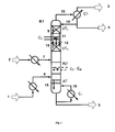
- the inventive method is partially with the help of Fig. 1 to 3 exemplified.
- the Fig. 1 to 3 show the inventive method without any subsequent steps such as disproportionation, further transesterification or purification in any other columns.
- An embodiment of the return of the recovered heat of condensation is only in Fig. 2 shown.
- Fig. 1 describes a reactive rectification in the transesterification column with intermediate condenser in general.
- Fig. 2 describes a reactive rectification with external arrangement of the intermediate condenser and combination with the evaporation of the dialkyl carbonate for the return of the resulting heat of condensation.
- Fig. 3 describes a reactive rectification with external arrangement of the intermediate capacitor and external arrangement of the upper reinforcing member in a separate column.
- Fig. 1 shows a transesterification column K1, in which the two reactant streams, ie containing the aromatic hydroxy compound stream 2 and the dialkyl carbonate containing stream 1 in the region of a reaction zone RZ in the sense of a Jacobstromumesttechnik against each other and reacted to alkylaryl and small amounts of diaryl carbonates.
- the dialkyl carbonate-containing stream 1 can - in particular in continuous process - in addition to the dialkyl also parts of the aromatic hydroxy compound, obtained in the reaction aliphatic hydroxy compound R 1 -OH and / or R 2 -OH (reaction alcohol), very small amounts of at the transesterification incurred Alkylarylcarbonats and / or diaryl carbonate and in the reaction resulting undesirable minor components.
- the stream 1 containing the dialkyl carbonate can be, for example, 0 to 5% by weight, preferably 0.05 to 3% by weight and more preferably 0.05 to 2% by weight of the reaction alcohol, 0 to 40% by weight, preferably 0 to 10% by weight.
- the stream containing the dialkyl carbonate preferably contains from 50 to 100% by weight of dialkyl carbonate, based on the total weight of the dialkyl carbonate-containing stream, with the proportions of the individual abovementioned components adding to 100% by weight.
- the current containing the aromatic hydroxy compound stream 2 can - in particular in continuous process - in addition to the aromatic hydroxy compound and parts of the dialkyl carbonate obtained in the transesterification Alkylarylcarbonat and / or diaryl carbonate, in very small amounts of the reaction alcohol and undesired by-products formed in the reaction.
- the stream 2 containing the aromatic hydroxy compound can be used to feed the catalyst into the transesterification column.
- the content of catalyst preferably 0 to 5 wt .-%, based on the total weight of the aromatic hydroxy compound-containing stream.
- the stream containing the aromatic hydroxy compound preferably contains from 50 to 100% by weight of aromatic hydroxy compound, based on the total weight of the stream containing the aromatic hydroxy compound, the proportions of the individual abovementioned components adding up to 100% by weight.
- the stream 1 containing the dialkyl carbonate is evaporated before introduction into the column K1 and possibly superheated.
- the stream 2 containing the aromatic hydroxy compound is heated before being introduced into the column K1.
- the educt streams 7 and 8, in each case after evaporation and optionally overheating or after heating, are conducted in the reaction zone RZ in countercurrent to each other, ie the containing the aromatic hydroxy compound stream 7 is at the upper end of the reaction zone RZ in heated, liquid form and the Dialkyl carbonate-containing stream 8 is supplied at the lower end of the reaction zone in gaseous or optionally slightly superheated.
- the resulting in the reaction aliphatic hydroxy compound R 1 -OH and / or R 2 -OH is withdrawn in vapor form together with not yet reacted dialkyl carbonate at the top of the column (13) and the less volatile alkylaryl carbonate together with not yet reacted amounts of the aromatic hydroxy compound, diaryl carbonate and optionally further low-volatility compounds taken as a liquid stream at the bottom of the column K1 (5).
- the energy required to set the desired temperature profile can be effected, inter alia, at the bottom of the column by one or more evaporators E 1 .
- the liquid mixture (15) flowing out of the stripping section or, if the stripping section is not present, out of the reaction zone is partially evaporated.
- stream 16 only steam or a vapor-liquid mixture (stream 16) is obtained at the outlet of the evaporator.
- the steam contained in the stream 16 is supplied to the stripping section (AT) from below or, if no stripping section is present, to the reaction zone from below.
- heat can be supplied by additional intermediate evaporators E 2 -E N.
- the alkylaryl carbonate formed and the diaryl carbonate are concentrated, the disproportionation reaction of alkylaryl carbonate and diaryl carbonate being already used to a greater extent in this part of the column K1 as a result of the depletion of dialkyl carbonate.
- the concentration of the aliphatic hydroxy compound formed in the reaction and of the excess dialkyl carbonate takes place.
- a content of aromatic hydroxy compound (s) in the distillate 4 from 0 to 40 wt .-%, preferably 0 to 10 wt .-%, particularly preferably from 0 to 5 wt .-%, based on the total weight of the distillate 4, can be adjusted .
- the reinforcement part is divided into at least two sections, the upper and the lower reinforcing member, with an intermediate capacitor C 2 between the upper reinforcing member VT 2 and the lower reinforcing member VT 1 .
- This intermediate capacitor C 2 condenses a part of the vapors 10 rising from the lower enrichment part VT 1.
- the vaporous mixture 10 entering the intermediate capacitor C 2 preferably contains 10 to 70% by weight of aromatic hydroxy compound.
- the condensation temperature in the intermediate capacitor C 2 is therefore significantly higher due to relatively high amounts of aromatic hydroxy compound compared to the condensation temperature in the top condenser C1.
- the condensation temperature in the intermediate condenser may preferably be in the range from 100 to 300 ° C., more preferably from 120 to 250 ° C., very preferably from 150 to 240 ° C. and preferably in the range from 0 to 250 in the top condenser ° C, more preferably from 40 to 200 ° C.
- the resulting in the intermediate capacitor C 2 condensate 12 and the effluent from the overlying upper reinforcing member VT 2 liquid 11 is passed to the lower reinforcing member VT 1 .
- the vaporous mixture after the intermediate condenser enters the upper reinforcing part VT 2 .
- the steam 13 coming from the upper enrichment part VT 2 is condensed as far as possible in the condenser C1, the condensate being partially returned as reflux to the upper enrichment part VT 2 (14) and partly taken off as distillate flow 4.
- the distillate stream 4 contains essentially the dialkyl carbonate used in excess and the corresponding resulting in the reaction aliphatic hydroxy compound R 1 -OH and / or R 2 -OH and optionally small amounts of the aromatic hydroxy compound.
- the remaining vapor mixture from the condenser C1 is removed as vapor stream 3.
- the heat of condensation liberated in the intermediate capacitor C 2 can be returned directly or indirectly to the process as described above for the process according to the invention (In Fig. 1 Not shown).
- Fig. 2 shows a particularly preferred embodiment of the method according to the invention, in which the intermediate capacitor is carried out separately outside the column and used in the condensation of the stream 10 in the intermediate capacitor C 2 condensation heat for the evaporation of used in symbolsstromumesttechnik in the transesterification column K1, containing dialkyl carbonate stream 1 used becomes.
- the stream 1 containing the dialkyl carbonate is fed to an evaporation unit C 2 , completely or partially evaporated and optionally still superheated.
- the vaporous mixture 10 of the lower amplifying part VT 1 is passed to the intermediate capacitor C 2 , where it partially condenses.
- Fig. 3 shows a further particularly preferred embodiment of the method according to the invention, in which the intermediate capacitor C 2 and the upper reinforcing member VT 2 are not integrated into the transesterification column K1 but are designed separately outside the column K1.
- the vaporous mixture 10 coming from the lower enrichment part VT 1 is fed to the intermediate condenser C 2 and partially condensed there.
- the remaining steam is supplied to the upper enrichment part VT 2 , which is housed in a separate column K2.
- the liquid 11 coming from the upper reinforcing part VT 2 is supplied to the lower reinforcing part together with the condensate 12 from the intermediate capacitor C 2 (FIG. 12 a).
- the steam 13 coming from the upper enrichment part VT 2 is condensed as far as possible, the condensate being partially returned as reflux to the upper enrichment part VT 2 (14) and partly taken off as distillate stream 4.
- the distillate stream 4 contains essentially the dialkyl carbonate used in excess and the corresponding resulting in the reaction aliphatic hydroxy compound R 1 -OH and / or R 2 -OH and optionally small amounts of the aromatic hydroxy compound.
- the remaining vapor mixture from the condenser C1 is removed as vapor stream 3. Otherwise, this corresponds to Fig. 3 shown method in Fig. 1 shown.
- the preceding explanations for Fig. 1 therefore apply analogously.
- the transesterification column according to the invention preferably has a diameter D RZ of 400 to 20,000 mm in the region of the reaction zone and the reaction zone has a length L RZ of 5,000 to 60,000 mm. Further preferably, the transesterification column according to the invention has a number of theoretical stages n Rz of from 5 to 50 in the reaction zone .
- the reaction zone can also have a number of reheaters n E.
- the ratio of the number of reheater n E in the reaction zone to the number of theoretical stages n RZ is preferably 0 to 2.
- the transesterification column according to the invention in the region of the optional stripping section has a diameter D AT of 100 to 20,000 mm and the stripping section has a length L AT of 100 to 20,000 mm.
- the transesterification column according to the invention preferably has a number of theoretical stages n AT of from 0 to 20 in the stripping section.
- the reinforcing part of the transesterification column according to the invention preferably has a diameter D VT of 200 to 10,000 mm and the entire region of the reinforcing part - including optionally present upper and lower reinforcing part and intermediate condenser - a length L VT of 100 to 30,000 mm, preferably 500 to 30,000 mm. Further preferably, reinforcing member has a total of a number of theoretical stages n VT of 2 to 20.
- the lower reinforcing part of the transesterification column according to the invention has a diameter D VT1 of 200 to 10,000 mm and a length L VT1 of 200 to 10,000 mm
- the upper reinforcing part of the transesterification column according to the invention has a diameter D VT2 of 200 to 10,000 mm and a length L VT2 from 200 to 10,000 mm.
- the ratio of the diameter of the lower reinforcing member to the column diameter in the reaction zone D VT1 : D RZ is preferably 0.3 to 1
- the ratio of the diameter of the upper reinforcing member to column diameter in the reaction zone D VT2 : D RZ is preferably 0.1 to 1 ,
- the intermediate condenser of the transesterification column according to the invention has a length L C2 of 100 to 10,000 mm and the ratio of diameter of the intermediate condenser to column diameter in the reaction zone D C2 : D Rz is preferably from 0.1 to 1.
- Intermediate capacitor has a heat transfer area A C2 of 1 to 5000 m 2 .
- the intermediate condenser can be integrated into the column or designed as a separate intermediate condenser outside the transesterification column. Furthermore, the intermediate condenser and the upper section of the reinforcing part can not be integrated into the transesterification column, but can also be accommodated separately outside the transesterification column.
- the intermediate capacitor various constructions are possible according to the invention, e.g. Plate heat exchanger or tube bundle heat exchanger. Such constructions are known to the person skilled in the art.
- the above-mentioned dimensions and characteristics of the transesterification column according to the invention are preferably for a product amount of more than 100 kg / h, wherein the product amount is to be understood as meaning the sum of the alkylaryl carbonate and / or diaryl carbonate contained in the bottom product.
- a conversion of the given dimensions to smaller amounts of product is familiar to the expert. Also from such conversions resulting transesterification columns are the subject of the present invention.
- Exemplary and also particularly preferred embodiments of the column according to the invention are the Fig. 1 to 3 refer to.
- the transesterification column is operated at a top pressure (above VT 2 ) of 3.6 bar and a reflux ratio of 1.15.
- a temperature of 230 ° C and in the reaction zone, a mean reaction temperature of 215 ° C is set in the bottom of the column.
- a sump evaporator E 1 and intermediate evaporator E 2 -E 4 in the reaction zone are operated with heating steam at a vapor pressure of 35 bar, wherein a natural circulation evaporator is used as bottom evaporator E 1 and used as an intermediate evaporator on the reaction trays integrated heating coil.
- the inlet temperature into the intermediate condenser is 205 ° C, the outlet temperature 193 ° C and the cooling capacity 57 kW.
- the heat of condensation produced during the intermediate condensation can be used to generate heating steam with a heating steam pressure of 8 bar (taut temperature: 170.4 ° C.).
- the required heating power for the evaporation of the dimethyl carbonate-containing stream is 52 kW.
- the evaporation and overheating of the dimethyl carbonate is carried out at a temperature of 135 to 152 ° C, to which the steam used in the intermediate condenser can be used easily.
- the transesterification column is operated at a top pressure (above VT 2 ) of 2 bar and a reflux ratio of 1.15.
- the phenol content in the distillate was 2% by weight.
- a temperature of 227 ° C and in the reaction zone, a mean reaction temperature of 200 ° C is set in the bottom of the column.
- a sump evaporator E 1 is operated with heating steam at a vapor pressure of 35 bar, wherein a natural circulation evaporator is used as bottom evaporator.
- the inlet temperature into the intermediate condenser is 190 ° C, the outlet temperature 183 ° C and the cooling capacity 46 kW.
- the heat of condensation produced during the intermediate condensation can be used to generate heating steam with a heating steam pressure of 8 bar (taut temperature: 170.4 ° C.).
- the vaporization and overheating of the dimethyl carbonate is carried out at a temperature of 122 to 153 ° C, to which the steam used in the intermediate condenser can be used easily.
- the required heating power for the evaporation of the dimethyl carbonate-containing stream is 46 kW.
- the transesterification column was operated without intermediate condenser. To achieve a phenol content of 2% by weight in the distillate, the reflux ratio had to be increased to 2.
- the cooling capacity of the top condenser C1 was 190 kW, that of the evaporator 144 kW.
- the condensation in the top condenser C1 was carried out at temperatures between 125 and 97 ° C.
- the material flow in the column energy is removed at a higher temperature level than the top condenser, so that the energy for the evaporation of a column of the supplied stream can be used. This is associated with saving considerable amounts of energy.
Landscapes
- Chemical & Material Sciences (AREA)
- Organic Chemistry (AREA)
- Chemical Kinetics & Catalysis (AREA)
- Organic Low-Molecular-Weight Compounds And Preparation Thereof (AREA)
- Low-Molecular Organic Synthesis Reactions Using Catalysts (AREA)
- Vaporization, Distillation, Condensation, Sublimation, And Cold Traps (AREA)
Abstract
Description
Gegenstand der Erfindung ist ein Verfahren zur Herstellung von Diarylcarbonaten und/oder Alkylarylcarbonaten aus Dialkylcarbonaten und aromatischen Hydroxyverbindungen unter Einsatz wenigstens einer Reaktionskolonne mit einem oder mehreren Zwischenkondensatoren zur Verbesserung der Wärmeintegration.The invention relates to a process for the preparation of diaryl carbonates and / or alkylaryl carbonates from dialkyl carbonates and aromatic hydroxy compounds using at least one reaction column with one or more intermediate condensers to improve the heat integration.
Die Herstellung von aromatischen und aliphatisch-aromatischen Kohlensäurestern (Carbonaten) durch Umesterung ausgehend von aliphatischen Kohlensäurestern und aromatischen Hydroxyverbindungen ist im Prinzip bekannt. Dabei handelt es sich um eine Gleichgewichtsreaktion, wobei die Lage des Gleichgewichts fast vollständig in Richtung der aliphatisch substituierten Carbonate verschoben ist. Daher ist es verhältnismäßig leicht, aus aromatischen Carbonaten und Alkoholen aliphatische Carbonate herzustellen. Um die Reaktion jedoch im umgekehrten Sinne in Richtung aromatischer Carbonate durchzuführen, ist es notwendig, das sehr ungünstig liegende Gleichgewicht effektiv auf die Seite der aromatischen Carbonate zu verschieben, wobei nicht nur sehr aktive Katalysatoren, sondern auch geeignete Verfahrensführungen zur Anwendung gelangen müssen.The preparation of aromatic and aliphatic-aromatic carbonic acid esters (carbonates) by transesterification starting from aliphatic carbonic acid esters and aromatic hydroxy compounds is known in principle. This is an equilibrium reaction, with the equilibrium position being shifted almost completely in the direction of the aliphatically substituted carbonates. Therefore, it is relatively easy to produce aliphatic carbonates from aromatic carbonates and alcohols. However, in order to carry out the reaction in the opposite direction in the direction of aromatic carbonates, it is necessary to shift the very unfavorable equilibrium effectively to the side of the aromatic carbonates, whereby not only very active catalysts but also suitable process routes must be used.
Es ist bekannt, derartige Gleichgewichtsreaktionen in Kolonnen durchzuführen und sie auf diese Weise vorteilhaft in Richtung der gewünschten Produktbildung zu verschieben (z.B.
In den bekannten Verfahren erfolgt die Umesterung daher auch vorzugsweise kontinuierlich im Sinne einer Gegenstromumesterung in einer oder mehreren Reaktionskolonnen.In the known methods, therefore, the transesterification is also preferably carried out continuously in the sense of a countercurrent transesterification in one or more reaction columns.
In
Bei einer Ausführung mit Verstärkungsteil enthält das am Kopf der Kolonne entnommene dampfförmige Gemisch im Wesentlichen das bei der Reaktion im Überschuss eingesetzte Dialkylcarbonat und den entsprechenden, bei der Reaktion entstehenden Alkohol und die Kondensation des Gemisches erfolgt bei einer Temperatur, die unterhalb der Verdampfungstemperatur des Dialkylcarbonats bei dem in der Reaktion vorliegenden Druck liegt, mit der Folge, das die anfallende Kondensationswärme im Vergleich zur Temperatur in der Reaktionszone nur auf niedrigem Temperaturniveau abgeführt werden kann. Führt man die Umesterungskolonne ohne einen Verstärkungsteil aus, so enthält das am Kopf der Kolonne entnommene Dampfgemisch und somit auch das Destillat der Kolonne nicht unerhebliche Mengen der zur Reaktion eingesetzten aromatischen Hydroxyverbindungen und ggf. auch noch schwerer siedende Komponenten.In an embodiment with a reinforcing part, the vapor mixture taken off at the top of the column essentially contains the excess used in the reaction Dialkyl carbonate and the corresponding resulting in the reaction of alcohol and the condensation of the mixture is carried out at a temperature which is below the vaporization temperature of the dialkyl carbonate at the pressure present in the reaction, with the result that the heat of condensation compared to the temperature in the reaction zone can be dissipated only at a low temperature level. If the transesterification column is carried out without a reinforcing part, the vapor mixture taken off at the top of the column and thus also the distillate of the column contains not insignificant amounts of the aromatic hydroxy compounds used for the reaction and optionally also heavier components.
Bei der Rückgewinnung des im Überschuss eingesetzten Dialkylcarbonats, z.B. durch destillative Trennung vom Reaktionsalkohol führen Anteile an höher siedenden Komponenten, wie beispielsweise der aromatischen Hydroxverbindung zu einem zusätzlichen Trennproblem oder zumindest zu einem erhöhten Temperaturniveau bei der Wärmezufuhr..In the recovery of the excess dialkyl carbonate, e.g. By distillative separation of the reaction alcohol portions of higher-boiling components, such as the aromatic hydroxy compound to an additional separation problem or at least to an elevated temperature level in the heat supply ..
Die
Ohne entsprechend effiziente Energieintegration ist der Energieverbrauch der vorangehend beschriebenen Verfahren bekanntermaßen hoch, was wiederum die Vorteilhaftigkeit der phosgenfreien Herstellung von Arylcarbonaten aus ökologischer und ökonomischer Hinsicht in Frage stellt.Without correspondingly efficient energy integration, the energy consumption of the processes described above is known to be high, which in turn puts into question the advantageousness of the phosgene-free preparation of aryl carbonates from an ecological and economic point of view.
Es bestand demnach weiterhin Bedarf, ein Verfahren zur Herstellung von aromatischen Carbonaten, d.h. Diaryl- und/oder Alkylarylcarbonaten, vorzugsweise Diarylcarbonaten, bereitzustellen, welches die vorangehend genannten Nachteile nicht aufweist und in welchem gegenüber den vorangehend genannten bekannten Verfahren eine Energieintegration in effizienter Weise möglich ist bzw. eine verbesserte Energieintegration erreicht werden kann.Thus, there has remained a need to provide a process for the preparation of aromatic carbonates, i. Diaryl and / or Alkylarylcarbonaten, preferably Diarylcarbonaten to provide, which does not have the aforementioned disadvantages and in which over the aforementioned known methods, an energy integration is possible in an efficient manner and an improved energy integration can be achieved.
Die Aufgabe, die der Erfindung zugrunde lag, bestand demnach darin, ein Verfahren zur Herstellung von aromatischen Carbonaten, d.h. Diaryl- und/oder Alkylarylcarbonaten, vorzugsweise Diarylcarbonaten, bereitzustellen, in welchem gegenüber bekannten Verfahren eine Energieintegration in effizienter Weise möglich ist bzw. eine verbesserte Energieintegration erreicht werden kann.The object on which the invention was based was therefore to provide a process for the preparation of aromatic carbonates, ie diaryl and / or alkylaryl carbonates, preferably diaryl carbonates, in which over known processes a Energy integration is possible in an efficient manner or an improved energy integration can be achieved.
Diese Aufgabe wurde erfindungsgemäß dadurch gelöst, dass durch den geeigneten Einsatz eines oder mehrerer Zwischenkondensatoren in einem Verfahren zur Herstellung von aromatischen Carbonaten, d.h. Diaryl- und/oder Alkylarylcarbonaten, aus Dialkylcarbonaten und aromatischen Hydroxyverbindungen die Energieintegration bei einfacher Verfahrensführung deutlich verbessert werden kann.This object has been achieved according to the invention by the appropriate use of one or more intermediate condensers in a process for the preparation of aromatic carbonates, i. Diaryl and / or alkylaryl, from dialkyl carbonates and aromatic hydroxy compounds energy integration can be significantly improved with simple process control.
Gegenstand der vorliegenden Erfindung ist daher ein Verfahren zur Herstellung von wenigstens einem Diarylcarbonat und/oder Alkylarylcarbonat aus wenigstens einem Dialkylcarbonat und wenigstens einer aromatischen Hydroxyverbindung, wobei
- (a) wenigstens ein Dialkylcarbonat in Gegenwart wenigstens eines Umesterungskatalysators mit wenigstens einer aromatischen Hydroxyverbindung in einer Umesterungskolonne enthaltend wenigstens einen Verstärkungsteil im oberen Teil der Kolonne und wenigstens eine Reaktionszone unterhalb des Verstärkungsteils, welcher mindestens zwei Sektionen aufweist, umgesetzt werden,
- (b) der am Kopf der Umesterungskolonne entnommene Dampf in wenigstens einem Kondensator ganz oder teilweise kondensiert wird,
- (a) at least one dialkyl carbonate is reacted in the presence of at least one transesterification catalyst with at least one aromatic hydroxy compound in a transesterification column comprising at least one enrichment section in the upper section of the column and at least one reaction zone below the reinforcement section comprising at least two sections;
- (b) the vapor taken off at the head of the transesterification column is completely or partially condensed in at least one condenser,
Im Rahmen der Erfindung hergestellte Diarylcarbonate sind bevorzugt solche der allgemeinen Formel (I)
Diarylcarbonate der allgemeinen Formel (I) sind beispielsweise: Diphenylcarbonat, Methylphenylphenyl-carbonate und Di-(methylphenyl)-carbonate, auch als Gemisch, wobei die Stellung der Methylgruppe an den Phenylringen beliebig sein kann, sowie Dimethylphenyl-phenyl-carbonate und Di-(dimethylphenyl)-carbonate, auch als Gemisch, wobei die Stellung der Methylgruppen an den Phenylringen beliebig sein kann, Chlorphenyl-phenyl-carbonate und Di-(chlorphenyl)-carbonate, wobei die Stellung der Methylgruppe an den Phenylringen beliebig sein kann, 4-Ethylphenyl-phenyl-carbonat, Di-(4-ethylphenyl)-carbonat, 4-n-Propylphenyl-phenyl-carbonat, Di-(4-n-propylphenyl)-carbonat, 4-iso-Propylphenyl-phenyl-carbonat, Di-(4-iso-propylphenyl)-carbonat, 4-n-Butylphenyl-phenyl-carbonat, Di-(4-n-butylphenyl)-carbonat, 4-iso-Butylphenyl-phenyl-carbonat, Di-(4-iso-butylphenyl)-carbonat, 4-tert-Butylphenyl-phenyl-carbonat, Di-(4-tert-butylphenyl)-carbonat, 4-n-Pentylphenyl-phenyl-carbonat, Di-(4-n-pentylphenyl)-carbonat, 4-n-Hexylphenyl-phenyl-carbonat, Di-(4-n-hexylphenyl)-carbonat, 4-iso-Octylphenyl-phenyl-carbonat, Di-(4-iso-octylphenyl)-carbonat,4-n-Nonylphenyl-phenyl-carbonat, Di-(4-n-nonylphenyl)-carbonat, 4-Cyclohexylphenyl-phenyl-carbonat, Di-(4-cyclohexylphenyl)-carbonat, 4-(1-Methyl-1-phenylethyl)-phenyl-phenyl-carbonat, Di-[4-(1-methyl-1-phenylethyl)-phenyl]-carbonat, Biphenyl-4-yl-phenyl-carbonat, Di-(biphenyl-4-yl)-carbonat, (1-Naphthyl)-phenyl-carbonat, (2-Naphthyl)-phenyl-carbonat, Di-(1-naphthyl)-carbonat, Di-(2-naphthyl)-carbonat, 4-(1-Naphthyl)-phenyl-phenyl-carbonat, 4-(2-Naphthyl)-phenyl-phenyl-carbonat, Di-[4-(1-naphthyl)phenyl]-carbonat, Di-[4-(2-naphthyl)phenyl]-carbonat, 4-Phenoxyphenyl-phenyl-carbonat, Di-(4-phenoxyphenyl)-carbonat, 3-Pentadecylphenyl-phenyl-carbonat, Di-(3-pentadecylphenyl)-carbonat, 4-Tritylphenylphenyl-carbonat, Di-(4-tritylphenyl)-carbonat, Methylsalicylat-phenyl-carbonat, Di-(methylsalicylat)-carbonat, Ethylsalicylat-phenyl-carbonat, Di-(ethylsalicylat)-carbonat, n-Propylsalicylat-phenyl-carbonat, Di-(n-propylsalicylat)-carbonat, iso-Propylsalicylat-phenyl-carbonat, Di-(iso-propylsalicylat)-carbonat, n-Butylsalicylat-phenyl-carbonat, Di-(n-butylsalicylat)-carbonat, iso-Butylsalicylat-phenyl-carbonat, Di-(iso-butylsalicylat)-carbonat, tert-Butylsalicylat-phenyl-carbonat, Di-(tert-butylsalicylat)-carbonat, Di-(phenylsalicylat)-carbonat und Di-(benzylsalicylat)-carbonat.Diarylcarbonates of the general formula (I) are, for example: diphenyl carbonate, methylphenylphenyl carbonates and di (methylphenyl) carbonates, also as a mixture, where the position of the methyl group on the phenyl rings may be arbitrary, and dimethylphenyl-phenyl-carbonates and di ( dimethylphenyl) carbonates, also as a mixture, wherein the position of the methyl groups on the phenyl rings may be arbitrary, chlorophenyl-phenyl-carbonates and di (chlorophenyl) carbonates, wherein the position of the methyl group on the phenyl rings may be arbitrary, 4-ethylphenyl phenyl carbonate, di- (4-ethylphenyl) carbonate, 4-n-propylphenyl phenyl carbonate, di- (4-n-propylphenyl) carbonate, 4-iso-propylphenyl phenyl carbonate, di- ( 4-iso-propylphenyl) carbonate, 4-n-butylphenyl phenyl carbonate, di (4-n-butylphenyl) carbonate, 4-iso-butylphenyl phenyl carbonate, di (4-iso-butylphenyl) carbonate, 4-tert-butylphenyl phenyl carbonate, di- (4-tert-butylphenyl) carbonate, 4-n-pentylphenyl phenyl carbonate, di- (4-n-pentylphenyl) -car carbonate, 4-n-hexylphenyl phenyl carbonate, di- (4-n-hexylphenyl) carbonate, 4-iso-octylphenyl phenyl carbonate, di- (4-iso-octylphenyl) carbonate, 4-n- Nonylphenyl phenyl carbonate, di- (4-n-nonylphenyl) carbonate, 4-cyclohexylphenyl phenyl carbonate, di (4-cyclohexylphenyl) carbonate, 4- (1-methyl-1-phenylethyl) phenyl phenyl carbonate, di- [4- (1-methyl-1-phenylethyl) phenyl] carbonate, biphenyl-4-yl phenyl carbonate, di (biphenyl-4-yl) carbonate, (1-naphthyl ) -phenyl carbonate, (2-naphthyl) phenyl carbonate, di (1-naphthyl) carbonate, di (2-naphthyl) carbonate, 4- (1-naphthyl) -phenyl phenyl carbonate, 4- (2-naphthyl) -phenyl-phenyl carbonate, di- [4- (1-naphthyl) phenyl] carbonate, di- [4- (2-naphthyl) phenyl] carbonate, 4-phenoxyphenyl-phenyl carbonate, di (4-phenoxyphenyl) carbonate, 3-pentadecylphenyl phenyl carbonate, di (3-pentadecylphenyl) carbonate, 4-trityl phenyl phenyl carbonate, di (4-trityl phenyl) carbonate, methyl salicylate phenyl carbonate, di (methyl salicylate) carbonate, ethyl salicylate phenyl carbonate, di- (ethylsalicy lat) carbonate, n-propyl salicylate phenyl carbonate, di (n-propyl salicylate) carbonate, iso-propyl salicylate phenyl carbonate, di (iso-propyl salicylate) carbonate, n-butyl salicylate phenyl carbonate, di - (n-butylsalicylate) carbonate, iso-butyl salicylate phenyl carbonate, di (iso-butylsalicylate) carbonate, tert-butyl salicylate phenyl carbonate, di- (tert-butylsalicylate) carbonate, di- (phenylsalicylate) carbonate and di- (benzylsalicylate) carbonate.
Bevorzugte Diarylcarbonate sind: Diphenylcarbonat, 4-tert-Butylphenyl-phenyl-carbonat, Di-(4-tert-butylphenyl)-carbonat, Biphenyl-4-yl-phenyl-carbonat, Di-(biphenyl-4-yl)-carbonat, 4-(1-Methyl-1-phenylethyl)-phenyl-phenyl-carbonat und Di-[4-(1-methyl-1-phenylethyl)-phenyl]-carbonat.Preferred diaryl carbonates are: diphenyl carbonate, 4-tert-butylphenyl phenyl carbonate, di (4-tert-butylphenyl) carbonate, biphenyl-4-yl phenyl carbonate, di (biphenyl-4-yl) carbonate, 4- (1-methyl-1-phenylethyl) -phenyl-phenyl-carbonate and di- [4- (1-methyl-1-phenylethyl) -phenyl] -carbonate.
Besonders bevorzugt ist Diphenylcarbonat.Particularly preferred is diphenyl carbonate.
Im Rahmen der Erfindung bevorzugt eingesetzte Dialkylcarbonate sind solche der Formel (II)

C1-C4-Alkyl steht im Rahmen der Erfindung beispielsweise für Methyl, Ethyl, n-Propyl, iso-Propyl, n-Butyl, sec.-Butyl, tert.-Butyl, C1-C6-Alkyl darüber hinaus beispielsweise für n-Pentyl, 1-Methylbutyl, 2-Methylbutyl, 3-Methylbutyl, neo-Pentyl, 1-Ethylpropyl, Cyclohexyl, Cyclopentyl, n-Hexyl, 1,1-Dimethylpropyl, 1,2-Dimethylpropyl, 1-Methylpentyl, 2-Methylpentyl, 3-Methylpentyl, 4-Methylpentyl, 1,1-Dimethylbutyl, 1,2-Dimethylbutyl, 1,3-Dimethylbutyl, 2,2-Dimethylbutyl, 2,3-Dimethylbutyl, 3,3-Dimethylbutyl, 1-Ethylbutyl, 2-Ethylbutyl, 1,1,2-Trimethylpropyl, 1,2,2-Trimethylpropyl, 1-Ethyl-1-methylpropyl oder 1-Ethyl-2-methylpropyl, C1-C34-Alkyl darüber hinaus beispielsweise für n-Heptyl und n-Octyl, Pinakyl, Adamantyl, die isomeren Menthyle, n-Nonyl, n-Decyl, n-Dodecyl, n-Tridecyl, n-Tetradecyl, n-Hexadecyl oder n-Octadecyl. Gleiches gilt für den entsprechenden Alkylrest beispielsweise in Aralkyl- bzw. Alkylarylresten. Alkylenreste in den entsprechenden Hydroxyalkyl- oder Aralkyl- bzw. Alkylarylresten stehen beispielsweise für die den vorangehenden Alkylresten entsprechenden Alkylenreste. In the context of the invention, C 1 -C 4 -alkyl is, for example, methyl, ethyl, n-propyl, isopropyl, n-butyl, sec-butyl, tert-butyl, C 1 -C 6 -alkyl, moreover, for example for n-pentyl, 1-methylbutyl, 2-methylbutyl, 3-methylbutyl, neo-pentyl, 1-ethylpropyl, cyclohexyl, cyclopentyl, n-hexyl, 1,1-dimethylpropyl, 1,2-dimethylpropyl, 1-methylpentyl, 2 Methylpentyl, 3-methylpentyl, 4-methylpentyl, 1,1-dimethylbutyl, 1,2-dimethylbutyl, 1,3-dimethylbutyl, 2,2-dimethylbutyl, 2,3-dimethylbutyl, 3,3-dimethylbutyl, 1-ethylbutyl , 2-ethylbutyl, 1,1,2-trimethylpropyl, 1,2,2-trimethylpropyl, 1-ethyl-1-methylpropyl or 1-ethyl-2-methylpropyl, C 1 -C 34 -alkyl furthermore, for example, for n- Heptyl and n-octyl, pinacyl, adamantyl, the isomeric menthyls, n-nonyl, n-decyl, n-dodecyl, n-tridecyl, n-tetradecyl, n-hexadecyl or n-octadecyl. The same applies to the corresponding alkyl radical, for example in aralkyl or alkylaryl radicals. Alkylene radicals in the corresponding hydroxyalkyl or aralkyl or alkylaryl radicals are, for example, the alkylene radicals corresponding to the preceding alkyl radicals.
Aryl steht für einen carbocyclischen aromatischen Rest mit 6 bis 34 Gerüstkohlenstoffatomen. Gleiches gilt für den aromatischen Teil eines Arylalkylrestes, auch Aralkylrest genannt, sowie für Arylbestandteile komplexerer Gruppen, wie z.B. Arylcarbonylresten.Aryl represents a carbocyclic aromatic radical having 6 to 34 skeleton carbon atoms. The same applies to the aromatic part of an arylalkyl radical, also called aralkyl radical, and to aryl constituents of more complex groups, such as e.g. Arylcarbonyl.
Arylalkyl bzw. Aralkyl bedeutet jeweils unabhängig einen geradkettigen, cyclischen, verzweigten oder unverzweigten Alkyl-Rest nach vorstehender Definition, der einfach, mehrfach oder vollständig durch Aryl-Reste gemäß vorstehender Definition substituiert sein kann. Arylalkyl or aralkyl each independently a straight-chain, cyclic, branched or unbranched alkyl radical as defined above which is simple, can be substituted by aryl radicals as defined above, multiply or fully.
Die vorangehenden Aufzählungen sind beispielhaft und nicht als Limitierung zu verstehen.The preceding listings are exemplary and not limiting.
Bevorzugte Dialkylcarbonate sind Dimethylcarbonat, Diethylcarbonat, Di(n-propyl)carbonat, Di(iso-propyl)carbonat, Di(n-butyl)carbonat, Di(sec-butyl)carbonat, Di(tert-butyl)carbonat oder Dihexylcarbonat. Besonders bevorzugt sind Dimethylcarbonat oder Diethylcarbonat. Ganz besonders bevorzugt ist Dimethylcarbonat.Preferred dialkyl carbonates are dimethyl carbonate, diethyl carbonate, di (n-propyl) carbonate, di (iso-propyl) carbonate, di (n-butyl) carbonate, di (sec-butyl) carbonate, di (tert-butyl) carbonate or dihexyl carbonate. Particularly preferred are dimethyl carbonate or diethyl carbonate. Very particular preference is given to dimethyl carbonate.
Im Rahmen der Erfindung geeignete aromatische Hydroxyverbindungen sind bevorzugt solche der allgemeinen Formel (III)

Solche aromatischen Hydroxyverbindungen sind beispielsweise: Phenol, o-, m- oder p-Kresol, auch als Gemisch der Kresole, Dimethylphenol, auch als Gemisch, wobei die Stellung der Methylgruppen am Phenolring beliebig sein kann, z.B. 2,4-, 2,6-, oder 3,4-Dimethylphenol, o-, m- oder p-Chlorphenol, o-, m- oder p-Ethylphenol, o-, m- oder p-n-Propylphenol, 4-iso-Propylphenol, 4-n-Butylphenol, 4-iso-Butylphenol, 4-tert-Butylphenol, 4-n-Pentylphenol, 4-n-Hexylphenol, 4-isoOctylphenol, 4-n-Nonylphenol, o-, m- oder p-Methoxyphenol, 4-Cyclohexylphenol, 4-(1-Methyl-1-phenylethyl)-phenol, Biphenyl-4-ol, 1-Naphthol, 2-1-Naphthol, 4-(1-Naphthyl)phenol, 4-(2-Naphthyl)-phenol, 4-Phenoxyphenol, 3-Pentadecylphenol, 4-Tritylphenol, Methylsalicylsäure, Ethylsalicylsäure, n-Propylsalicylsäuret, iso-Propylsalicylsäure, n-Butylsalicylsäure, iso-Butylsalicylsäure, tert-Butylsalicylsäure, Phenylsalicylsäure und Benzylsalicylsäure.Such aromatic hydroxy compounds are, for example: phenol, o-, m- or p-cresol, also as a mixture of cresols, dimethylphenol, also as a mixture, wherein the position of the methyl groups on the phenol ring may be arbitrary, e.g. 2,4-, 2,6- or 3,4-dimethylphenol, o-, m- or p-chlorophenol, o-, m- or p-ethylphenol, o-, m- or pn-propylphenol, 4-iso -Propylphenol, 4-n-butylphenol, 4-iso-butylphenol, 4-tert-butylphenol, 4-n-pentylphenol, 4-n-hexylphenol, 4-isoctylphenol, 4-n-nonylphenol, o-, m- or p -Methoxyphenol, 4-cyclohexylphenol, 4- (1-methyl-1-phenylethyl) phenol, biphenyl-4-ol, 1-naphthol, 2-1-naphthol, 4- (1-naphthyl) phenol, 4- (2 -Naphthyl) -phenol, 4-phenoxyphenol, 3-pentadecylphenol, 4-tritylphenol, methylsalicylic acid, ethylsalicylic acid, n-propylsalicylic acid, iso-propylsalicylic acid, n-butylsalicylic acid, iso-butylsalicylic acid, tert-butylsalicylic acid, phenylsalicylic acid and benzylsalicylic acid.
Bevorzugte Diarylverbindungen sind Phenol, 4-tert-Butylphenol, Biphenyl-4-ol und 4-(1-Methyl-1-phenylethyl)-phenol.Preferred diaryl compounds are phenol, 4-tert-butylphenol, biphenyl-4-ol and 4- (1-methyl-1-phenylethyl) phenol.
Besonders bevorzugt ist Phenol.Particularly preferred is phenol.
Im Rahmen der Erfindung hergestellte Alkylarylcarbonate sind bevorzugt solche der allgemeinen Formel (IV)

Bevorzugte Alkylarylcarbonate sind Methyl-phenyl-carbonat, Ethyl-phenyl-carbonat, Propyl-phenyl-carbonat, Butylphenyl-carbonat und Hexyl-phenyl-carbonat, Methyl-(o-kresyl)-carbonat, Methyl-(p-kresyl)-carbonat, Ethyl-(o-kresyl)-carbonat, Ethyl-(p-kresyl)-carbonat, Methyl- oder Ethyl-(p-chlorphenyl)-carbonat. Besonders bevorzugte Alkylarylcarbonate sind Methyl-phenyl-carbonat und Ethyl-phenyl-carbonat. Ganz besonders bevorzugt ist Methyl-phenyl-carbonat.Preferred alkylaryl carbonates are methyl phenyl carbonate, ethyl phenyl carbonate, propyl phenyl carbonate, butyl phenyl carbonate and hexyl phenyl carbonate, methyl (o-cresyl) carbonate, methyl (p-cresyl) carbonate , Ethyl (o-cresyl) carbonate, ethyl (p-cresyl) carbonate, methyl or ethyl (p-chlorophenyl) carbonate. Particularly preferred alkylaryl carbonates are methyl phenyl carbonate and ethyl phenyl carbonate. Very particular preference is given to methylphenyl carbonate.
Sowohl die für das erfindungsgemäße Verfahren geeigneten Dialkylcarbonate als auch die aromatischen Hydroxyverbindungen sind dem Fachmann bekannt und kommerziell erhältlich oder können nach dem Fachmann ebenfalls bekannten Verfahren hergestellt werden.Both the dialkyl carbonates which are suitable for the process according to the invention and the aromatic hydroxy compounds are known to the person skilled in the art and are commercially available or can be prepared by processes which are likewise known to the person skilled in the art.
Im erfindungsgemäßen Verfahren werden die aromatische(n) Hydroxyverbindung(en) und das oder die Dialkylcarbonat(e) bevorzugt im Molverhältnis von 1 : 0.1 bis 1 : 10, besonders bevorzugt von 1 : 0.2 bis 1 : 5, ganz besonders bevorzugt von 1 : 0.5 bis 1 : 3 eingesetzt. Dabei berücksichtigt das angegebene Molverhältnis nicht die Rückführung von aromatischer Hydroxyverbindung oder Dialkylcarbonat in die Umesterungskolonne über einen oder mehrere Kopfkondensator(en) (vgl. unter (b)) oder einen oder mehrere etwaig vorhandene(n) Sumpfverdampfer.In the process according to the invention, the aromatic hydroxy compound (s) and the dialkyl carbonate (s) are preferably in a molar ratio of from 1: 0.1 to 1:10, more preferably from 1: 0.2 to 1: 5, most preferably from 1: 0.5 to 1: 3 used. In this case, the stated molar ratio does not take into account the recycling of aromatic hydroxy compound or dialkyl carbonate into the transesterification column via one or more top condenser (s) (see under (b)) or one or more optional bottom evaporators.
Das erfindungsgemäße Verfahren wird in einer Umesterungskolonne durchgeführt. In bevorzugten Ausführungsformen des erfindungsgemäßen Verfahrens kann der am Sumpf dieser Umesterungskolonne entnommene Flüssigkeitsstrom - gegebenenfalls nach Aufkonzentrierung - in einem oder mehreren weiteren Schritten einer Disproportionierung, einer weiteren Umesterung und/oder Reinigung unterzogen werden. Bevorzugt können einzelne oder alle solche weiteren Schritte in einer oder mehreren weiteren Kolonnen erfolgen.The process according to the invention is carried out in a transesterification column. In preferred embodiments of the process according to the invention, the liquid stream taken off at the bottom of this transesterification column can, if appropriate after concentration, be subjected to disproportionation, further transesterification and / or purification in one or more further steps. Preferably, individual or all such further steps can take place in one or more further columns.
Als Umesterungskolonne oder gegebenenfalls zweite bzw. weitere Kolonne(n) kommen dem Fachmann bekannte Kolonnen in Frage. Dies sind beispielsweise Destillations- bzw. Rektifikationskolonnen, bevorzugt Reaktivdestillations- bzw. Reaktivrektifikationskolonnen.As a transesterification column or optionally second or further column (s) known to those skilled in columns come into question. These are, for example, distillation or rectification columns, preferably reactive distillation columns or reactive rectification columns.
Die Umesterungskolonne enthält wenigstens einen Verstärkungsteil im oberen Teil der Kolonne und wenigstens eine Reaktionszone unterhalb des Verstärkungsteils, welcher mindestens zwei Sektionen aufweist, wobei wenigstens ein Verstärkungsteil der Umesterungskolonne mit wenigstens einem Zwischenkondensator ausgestattet ist. Jede der zwei Sektionen weist unabhängig voneinander bevorzugt jeweils 0 bis 20, bevorzugt 0,1 bis 20 theoretische Stufen auf. Der Zwischenkondensator ist vorzugsweise zwischen den beiden Sektionen des Verstärkungsteils angebracht. In diesem Fall wird der Verstärkungsteil in einen oberen und einen unteren Verstärkungsteil geteilt.The transesterification column contains at least one enrichment section in the upper part of the column and at least one reaction zone below the reinforcement section, which has at least two sections, wherein at least one reinforcement section of the transesterification column is equipped with at least one intermediate condenser. Each of the two sections independently of one another preferably has 0 to 20, preferably 0.1 to 20 theoretical steps each. The intermediate capacitor is preferably mounted between the two sections of the reinforcing member. In this case, the reinforcing member is divided into upper and lower reinforcing members.
Die Umesterungskolonne wird bevorzugt im Gegenstrom betrieben, wobei vorzugsweise in wenigstens einer Reaktionszone dieser Kolonne die aromatische Hydroxyverbindung flüssig vom Kopf zum Sumpf geführt und das Dialkylcarbonat gasförmig diesem flüssigen Strom entgegengeführt wird. Dabei wird die Umesterungskolonne vorzugsweise so betrieben, dass man wenigstens einer Reaktionszone, bevorzugt in das obere Drittel der Reaktionszone, einen oder mehrere, die aromatische Hydroxyverbindung und gegebenenfalls gelösten Umesterungskatalysator enthaltende Ströme, bevorzugt mit der an dieser Stelle der Kolonne herrschenden Temperatur, flüssig oder mit nur geringem Gasanteil eindosiert, wobei der Gasanteil bevorzugt weniger als 20 Gew.-% beträgt. Zudem werden einer oder mehrere, das Dialkylcarbonat enthaltende Ströme in die Reaktionszone, bevorzugt im unteren Drittel dieser Reaktionszone, gleitet, wobei die Zudosierung vorzugsweise gasförmig oder überhitzt erfolgt. In bevorzugten Ausführungsformen kann die Überhitzung des Dampfstroms 0 bis 50 °C betragen. Des Weiteren richtet sich die Taupunktstemperatur bevorzugt nach dem in der Reaktionszone an der Zudosierstelle des jeweiligen Dialkylcarbonat enthaltenden Stromes vorliegenden Druck.The transesterification column is preferably operated in countercurrent, wherein preferably in at least one reaction zone of this column, the aromatic hydroxy compound is passed liquid from the head to the bottom and the dialkyl carbonate is passed in gaseous form this liquid stream. The transesterification column is preferably operated so that at least one reaction zone, preferably in the upper third of the reaction zone, one or more, the aromatic hydroxy compound and optionally dissolved transesterification catalyst containing streams, preferably with the prevailing at this point of the column temperature, liquid or metered with only a small proportion of gas, the gas fraction is preferably less than 20 wt .-%. In addition, one or more, the dialkyl carbonate-containing streams in the reaction zone, preferably in the lower third of this reaction zone, slides, wherein the metered addition is preferably carried out in gaseous or superheated. In preferred embodiments, the superheat of the vapor stream may be 0 to 50 ° C. Furthermore, the dew point temperature preferably depends on the pressure present in the reaction zone at the metering point of the respective dialkyl carbonate.
Nach Passieren der Reaktionszone(n) wird der Reaktionsalkohol, nach Durchlaufen des oder der Verstärkungsteile, am Kopf der Umesterungskolonne entnommen. Beim Reaktionsalkohol handelt es sich im Rahmen der Erfindung um den bei der Umesterung frei werdenden Alkohol, bevorzugt R1-OH bzw. R2-OH, wobei R1 und R2 die für die allgemeine Formel (II) genannte Bedeutung haben. Der am Kopf der Umesterungskolonne entnommene Strom enthält im Allgemeinen zusätzlich zum Reaktionsalkohol noch überschüssiges oder nicht umgesetztes Dialkylcarbonat. Aufgrund des oder der vorhandenen Verstärkungsteil(e) enthält dieser Strom nur geringe Mengen an höher siedenden Komponenten, wie z.B. der aromatischen Hydroxyverbindung. Der Verstärkungsteil dient zur Abtrennung der in der Reaktionszone mitverdampften höher siedenden Komponenten, wie z.B. der aromatischen Hydroxyverbindung oder Alkylarylcarbonat von den leichtsiedenden Reaktionsalkoholen oder Dialkylcarbonaten. Dies hat den Vorteil, dass die Trennung der Reaktionsalkohole von den Dialkylcarbonaten bei einem niedrigen Temperaturniveau durchgeführt werden kann.After passing through the reaction zone (s), the reaction alcohol is removed, after passing through the or the reinforcing parts, at the top of the transesterification column. In the context of the invention, the reaction alcohol is the alcohol released during the transesterification, preferably R 1 -OH or R 2 -OH, where R 1 and R 2 have the meaning given for the general formula (II). The stream taken off at the top of the transesterification column generally contains, in addition to the reaction alcohol, excess or unreacted dialkyl carbonate. Due to the existing reinforcing part (s), this stream contains only small amounts of higher-boiling components, such as the aromatic hydroxy compound. The reinforcing member serves to separate the higher-boiling components coevaporated in the reaction zone, such as, for example, the aromatic hydroxy compound or alkylaryl carbonate from the low-boiling reaction alcohols or dialkyl carbonates. This has the advantage that the separation of the reaction alcohols from the dialkyl carbonates can be carried out at a low temperature level.
Die Umesterungskolonne wird in bevorzugten Ausführungsformen unter Rückflussbedingungen betrieben. Unter Rückflussbedingungen ist eine solche Fahrweise zu verstehen, bei der man den Dampfstrom am oberen Ende des Verstärkungsteils teilweise oder vollständig kondensiert (vgl. unter (b)) und das dabei anfallende Kondensat teilweise oder vollständig wieder als Rücklauf auf das obere Ende des Verstärkungsteils zurückführt. Das Rücklaufverhältnis beträgt dabei bevorzugt 0,1 bis 20, besonders bevorzugt 0,1 bis 10 und ganz besonders bevorzugt 0,1 bis 3, wobei das Rücklaufverhältnis im Rahmen der Erfindung dem Gewichtsverhältnis von in die Kolonne zurückgeführtem Kondensat zu am Kopf der Kolonne entnommenem Dampf ohne zurückgeführtes Kondensat entspricht.The transesterification column is operated under reflux conditions in preferred embodiments. Reflux conditions are to be understood as such a procedure in which the vapor stream is partially or completely condensed at the upper end of the reinforcing part (see under (b)) and the resulting condensate is partly or completely returned to the upper end of the reinforcing part as reflux. The reflux ratio is preferably 0.1 to 20, particularly preferably 0.1 to 10 and very particularly preferably 0.1 to 3, wherein the reflux ratio in the context of the invention, the weight ratio of condensate returned to the column to withdrawn at the top of the column steam without recycled condensate corresponds.
In bevorzugten Ausführungsformen weist die Umesterungskolonne unterhalb einer Reaktionszone wenigstens einen Abtriebsteil auf.In preferred embodiments, the transesterification column has at least one stripping section below a reaction zone.
Die Umesterungskolonne kann weiterhin bevorzugt mit einem oder mehreren Sumpfverdampfer(n) ausgestattet sein. Bei Ausführung der Umesterungskolonne mit einem Abtriebsteil wird bevorzugt zusätzlich ein Sumpfverdampfer eingesetzt, welcher die aus dem Abtriebsteil ablaufende Flüssigkeit ganz oder teilweise verdampft. Dieser ganz oder teilweise verdampfte Flüssigkeitsstrom wird ganz oder teilweise wieder in die Umesterungskolonne zurückgeführt. Im Falle einer Ausführungsform ohne Abtriebsteil wird in einem gegebenenfalls eingesetzten Sumpfverdampfer die aus der Reaktionszone ablaufende Flüssigkeit ganz oder teilweise verdampft und ganz oder teilweise wieder in die Umesterungskolonne zurückgeführt.The transesterification column can furthermore preferably be equipped with one or more bottom evaporator (s). When carrying out the transesterification column with a stripping section is preferred additionally used a bottom evaporator, which evaporates the effluent from the stripping section liquid completely or partially. This completely or partially vaporized liquid flow is wholly or partly recycled back into the transesterification column. In the case of an embodiment without a stripping section, the liquid leaving the reaction zone is completely or partially evaporated in an optionally used bottoms evaporator and completely or partially recirculated to the transesterification column.
Bevorzugt ist der Verstärkungsteil der Umesterungskolonne, der mit wenigstens einem Zwischenkondensator ausgestattet ist, in einen unteren und einen oberen Verstärkungsteil (zwei Sektionen) unterteilt, wovon sich der untere Verstärkungsteil unterhalb des Zwischenkondensators und der obere Verstärkungsteil oberhalb des Zwischenkondensators befinden.Preferably, the reinforcing part of the transesterification column equipped with at least one intermediate condenser is divided into lower and upper reinforcing parts (two sections), of which the lower reinforcing part is below the intermediate condenser and the upper reinforcing part is above the intermediate condenser.
Der oder die Verstärkungsteil(e) mit wenigstens einem Zwischenkondensator können in bevorzugten Ausführungsformen zusammen mit dem oder den Reaktionsteil(en) und gegebenenfalls wenigstens einem Abtriebsteil in der Umesterungskolonne untergebracht werden. Dabei wird das aus der oder den Reaktionszone(n) kommende dampfförmige Gemisch von unten in eine untere Sektion des Verstärkungsteils bzw. gegebenenfalls den unteren Verstärkungsteil geleitet, wobei eine Abreicherung der aromatischen Hydroxyverbindung stattfindet. Das aus dieser unteren Sektion bzw. gegebenenfalls dem unteren Verstärkungsteil kommende dampfförmige Gemisch wird in einen Zwischenkondensator geleitet, wo dieses teilweise auskondensiert und das anfallende Kondensat am oberen Ende der unteren Sektion des Verstärkungsteils bzw. gegebenenfalls dem unteren Verstärkungsteil zugeführt wird.The reinforcing part (s) with at least one intermediate condenser can in preferred embodiments be accommodated together with the reaction part (s) and optionally at least one stripping part in the transesterification column. The vaporous mixture coming from the reaction zone (s) is directed from below into a lower section of the reinforcing part or, if appropriate, the lower reinforcing part, with depletion of the aromatic hydroxy compound taking place. The coming from this lower section or optionally the lower reinforcing member vapor mixture is passed into an intermediate condenser, where this partially condensed out and the resulting condensate at the upper end of the lower section of the reinforcing member or optionally the lower reinforcing member is supplied.
In einer weiteren bevorzugten Ausführungsform des erfindungsgemäßen Verfahrens wird der Zwischenkondensator nicht in die Umesterungskolonne integriert sondern als separater Zwischenkondensator außerhalb der Umesterungskolonne ausgeführt.In a further preferred embodiment of the process according to the invention, the intermediate condenser is not integrated into the transesterification column but is carried out as a separate intermediate condenser outside the transesterification column.
In einer weiteren bevorzugten Ausführungsform des erfindungsgemäßen Verfahrens werden Zwischenkondensator und die obere Sektion des Verstärkungsteils nicht in die Umesterungskolonne integriert sondern separat außerhalb der Umesterungskolonne untergebracht.In a further preferred embodiment of the process according to the invention, the intermediate condenser and the upper section of the reinforcing part are not integrated into the transesterification column but are accommodated separately outside the transesterification column.
Unterhalb der Reaktionszone und eines gegebenenfalls vorhandenen Abtriebsteils wird ein Gemisch enthaltend Alkylarylcarbonat, überschüssigem oder nichtumgesetztem Phenol, Diarylcarbonat, Umesterungskatalysatoren, Dialkylcarbonat, Reaktionsalkohol und bei der Reaktion entstehende oder bereits in den Edukten enthaltene schwersiedende Verbindungen erhalten.. Bei Verwendung eines Abtriebsteils wird der Gehalt an leichtsiedenden Verbindungen, wie beispielsweise Dialkylcarbonat und Reaktionsalkohol reduziert, wobei in Anwesenheit des Umesterungskatalysators unter Umständen weiteres Alkylarylcarbonat und/oder Diarylcarbonat gebildet werden. Die hierzu erforderliche Energie, wird bevorzugt durch einen oder mehrere Verdampfer zugeführt.Below the reaction zone and an optional stripping section is a mixture containing alkylaryl carbonate, excess or unreacted phenol, diaryl, transesterification, dialkyl, reaction and obtained in the reaction or already contained in the educts high-boiling compounds .. When using a stripping section, the content low-boiling compounds, such as dialkyl carbonate and reaction alcohol reduced, wherein in the presence of the transesterification under certain circumstances further alkylaryl carbonate and / or diaryl carbonate be formed. The energy required for this purpose is preferably supplied by one or more evaporators.
In allen Abschnitten der Umesterungskolonne, d.h. sowohl in Verstärkungs- und gegebenenfalls Abtriebsteil als auch in der Reaktionszone können Füllkörper oder geordnete Packungen zum Einsatz kommen. Die zu verwendenden Füllkörper bzw. geordneten Packungen sind die für Destillationen üblichen, wie sie beispielsweise in Ullmann's Encyclopädie der Technischen Chemie, 4. Aufl" Bd. 2, S. 528 ff. beschrieben sind. Als Beispiele für Füllkörper seien Raschig- oder Pall- und Novaloxringe, Berl-, Intalex- oder Torussättel, Interpackkörper und als Beispiele für geordnete Packungen seien Blech und Gewebepackungen (wie z.B. BX-Packungen, Montz Pak, Mellapak, Melladur, Kerapak und CY-Packung) aus verschiedenen Materialien, wie Glas, Steinzeug, Porzellan, Edelstahl, Kunststoff genannt. Bevorzugt sind Füllkörper und geordnete Packungen, die eine große Oberfläche, eine gute Benetzung sowie ausreichende Verweilzeit der Flüssigphase aufweisen. Diese sind beispielsweise Pall- und Novolaxringe, Berlsättel, BX-Packungen, Montz Pak, Mellapak, Melladur, Kerapak und CY-Packungen.In all sections of the transesterification column, i. Packings or ordered packings can be used both in the boosting and, if appropriate, stripping section and in the reaction zone. The fillers or ordered packings to be used are those which are customary for distillations, as described, for example, in Ullmann's Encyclopadie der Technischen Chemie, 4th ed., Vol. 2, page 528 et seq .. Examples of random packings are Raschig or palladium. and Novalox rings, Berl, Intalex or Torussättel, Interpackkörper and as examples of ordered packs are sheet metal and fabric packings (such as BX packs, Montz Pak, Mellapak, Melladur, Kerapak and CY pack) of various materials, such as glass, stoneware Preference is given to fillers and ordered packings which have a high surface area, good wetting and sufficient residence time of the liquid phase, for example Pall and Novolax rings, Berl's saddles, BX packings, Montz Pak, Mellapak, Melladur , Kerapak and CY packs.
Alternativ eignen sich auch Kolonnenböden, wie beispielesweise Sieb-, Glocken-, Ventil-, Tunnelböden. In der oder den Reaktionszone(n) der Umesterungskolonne sind Kolonnenböden mit hohen Verweilzeiten bei gutem Stoffaustausch, beispielsweise Glockenböden, Ventil- oder Tunnelböden mit hohen Überlaufwehren, besonders bevorzugt. Die theoretische Bodenzahl der Reaktionszone beträgt vorzugsweise 3 bis 50, besonders bevorzugt 10 bis 50 und ganz besonders bevorzugt 10 bis 40. Der Flüssigkeits-Hold-up beträgt vorzugsweise 1 bis 80%, besonders bevorzugt 5 bis 70% und ganz besonders bevorzugt 7 bis 60% des Kolonneninnenvolumens der Reaktionszone. Die genauere Auslegung der Reaktionszone(n), des gegebenenfalls zu verwendendes Abtriebsteils und des oder der Verstärkerteil(e) kann vom Fachmann vorgenommen werden.Alternatively, column bottoms, such as sieve, bell, valve, tunnel bottoms are suitable. In the reaction zone (s) of the transesterification column, column trays with high residence times with good mass transfer, for example bubble-cap trays, valve or tunnel trays with high overflow weirs, are particularly preferred. The theoretical plate number of the reaction zone is preferably 3 to 50, more preferably 10 to 50 and most preferably 10 to 40. The liquid hold-up is preferably 1 to 80%, more preferably 5 to 70% and most preferably 7 to 60 % of the column internal volume of the reaction zone. The more precise design of the reaction zone (s), the optionally used stripping section and the or the amplifier part (s) can be made by a person skilled in the art.
Die Temperatur der Reaktionszone(n) liegt bevorzugt im Bereich von 100 bis 300°C, besonders bevorzugt von 120 bis 250°C, ganz besonders bevorzugt von 150 bis 240°C. In bevorzugten Ausführungsformen wird in der Reaktionszone eine optimale Reaktionstemperatur einerseits durch die Wahl der Betriebsbedingungen und andererseits durch zusätzliche Wärmzufuhr im Bereich eines oder mehrerer Reaktionsböden eingestellt. Die Wärmezufuhr auf den Reaktionsböden kann dabei entweder durch Wärmetauscher oder über Reaktionsböden mit Möglichkeit zum Wärmeeintrag erfolgen. Es ist von Vorteil, die erfindungsgemäße Umesterung nicht nur bei Normaldruck, sondern auch bei erhöhtem oder erniedrigtem Druck durchzuführen. Der Druck der Reaktionszone liegt daher bevorzugt im Bereich von 0.5 bis 20 bar, besonders bevorzugt von 0.8 bis 15 bar, ganz besonders bevorzugt von 0.9 bis 10 bar. Bei den vorangehend und im Folgenden aufgeführten Druckangaben handelt es sich - sofern nichts anderes explizit erwähnt - um absolute Druckangaben.The temperature of the reaction zone (s) is preferably in the range of 100 to 300 ° C, more preferably from 120 to 250 ° C, most preferably from 150 to 240 ° C. In preferred embodiments, an optimum reaction temperature is set in the reaction zone on the one hand by the choice of operating conditions and on the other hand by additional heat in the range of one or more reaction trays. The heat supply to the reaction trays can be done either by heat exchangers or via reaction trays with possibility for heat input. It is advantageous to carry out the transesterification according to the invention not only at atmospheric pressure but also at elevated or reduced pressure. The pressure of the reaction zone is therefore preferably in the range from 0.5 to 20 bar, more preferably from 0.8 to 15 bar, most preferably from 0.9 to 10 bar. In the preceding and following Unless otherwise explicitly stated, the pressure values listed are absolute pressures.
Für die in der Umesterungskolonne auftretenden Reaktionsschritte können aus der Literatur bekannte Umesterungskatalysatoren eingesetzt werden. Dies sind aus der Literatur bekannte Umesterungskatalysatoren für die Dialkylcarbonat-Phenol-Umesterung, wie z. B. Hydride, Oxide, Hydroxide, Alkoholate, Amide und andere Salze von Alkali- und Erdalkalimetallen, wie von Lithium, Natrium, Kalium, Rubidium, Caesium, Magnesium und Calcium, bevorzugt Lithium, Natrium, Kalium, Magnesium und Calcium und besonders bevorzugt Lithium, Natrium und Kalium (vgl. z.B.
Weitere erfindungsgemäß einsetzbare Katalysatoren sind Metallverbindungen wie AlX3, TiX3, UX4, TiX4, VOX3, VX5, ZnX2, FeX3, PbX2 und SnX4, worin X für Halogen-, Acetoxy-, Alkoxy- oder Aryloxyreste steht (
Halogen bedeutet im Rahmen der Erfindung Fluor, Chlor oder Brom, bevorzugt Fluor oder Chlor, besonders bevorzugt Chlor.Halogen means in the context of the invention fluorine, chlorine or bromine, preferably fluorine or chlorine, more preferably chlorine.
Weitere erfindungsgemäß einsetzbare Katalysatoren sind zinnorganische Verbindungen der allgemeinen Formel (R11)4-X-Sn(Y)X, in der Y für einen Rest OCOR12, OH oder OR steht, wobei R12 C1-C12-Alkyl, C6-C12-Aryl oder C7-C13-Alkylaryl bedeutet, R11 unabhängig von R12 die Bedeutung von R12 hat und x eine ganze Zahl von 1 bis 3 bedeutet, Dialkylzinnverbindungen mit 1 bis 12 C-Atomen im Alkylrest oder Bis-(trialkylzinn)verbindungen, beispielsweise Trimethylzinnacetat, Triethylzinnbenzoat, Tributylzinnacetat, Triphenylzinnacetat, Dibutylzinndiacetat, Dibutylzinndilaurat, Dioctylzinndilaurat, Dibutylzinnadipinat, Dibutyldimethoxyzinn, Dimethylzinnglykolat, Dibutyldiethoxyzinn, Triethylzinnhydroxid, Hexaethylstannoxan, Hexabutylstannoxan, Dibutylzinnoxid, Dioctylzinnoxid, Butylzinntriisooctylat, Octylzinntriisooctylat, Butylstannonsäure und Octylstannonsäure in Mengen von 0,001 bis 20 Gew: % (vgl.
X-R2Sn-O-R2Sn-Y,
worin X und Y unabhängig voneinander OH, SCN, OR13, OCOR13 oder Halogen und R Alkyl, Aryl bedeuten soll, worin R13 die vorangehend für R12 genannte Bedeutung hat (
XR 2 Sn-OR 2 Sn-Y,
in which X and Y are, independently of one another, OH, SCN, OR 13 , OCOR 13 or halogen and R is alkyl, aryl, in which R 13 has the meaning given above for R 12 (
Als weitere erfindungsgemäß einsetzbare Katalysatoren kommen Bleiverbindungen, gegebenenfalls zusammen mit Triorganophosphanen, einer Chelatverbindung oder einem Alkalimetallhalogenid, beispielsweise Pb(OH)2-2PbCO3, Pb(OCO-CH3)2, Pb(OCO-CH3)2 ·2LiC1, Pb(OCO-CH3)2 · 2PPh3 in Mengen von 0,001 bis 1, bevorzugt von 0,005 bis 0,25 Mol pro Mol Dialkylcarbonat (
Weiterhin sind in den erfindungsgemäßen Verfahren heterogene Katalysatorsysteme einsetzbar. Solche sind beispielsweise Mischoxide aus Silizium und Titan, die durch gemeinsame Hydrolyse von Silizium und Titanhalogeniden erhältlich sind (
Bevorzugte Katalysatoren für das erfindungsgemäße Verfahren sind die vorangehend genannten Metallverbindungen AlX3, TiX3, UX4, TiX4, VOX3, VX5, ZnX2, FeX3, PbX2 und SnX4. Besonders bevorzugt sind AlX3, TiX4, PbX2 und SnX4, wovon beispielhaft Titantetrachlorid, Titantetramethoxid Titantetraphenoxid, Titantetraethoxid, Titantetraisopropylat, Titantetradodecylat, Zinntetraisooctylat und Aluminiumtriisopropylat genannt seien. Ganz besonders bevorzugt sind Metallverbindungen TiX4. Insbesondere bevorzugt sind Titantetramethoxid, Titantetraphenoxid und Titantetraethoxid.Preferred catalysts for the process according to the invention are the abovementioned metal compounds AlX 3 , TiX 3 , UX 4 , TiX 4 , VOX 3 , VX 5 , ZnX 2 , FeX 3 , PbX 2 and SnX 4 . Particular preference is given to AlX 3 , TiX 4 , PbX 2 and SnX 4 , examples of which include titanium tetrachloride, titanium tetramethoxide, titanium tetraphenoxide, titanium tetraethoxide, titanium tetraisopropylate, titanium tetradodecylate, tin tetraisooctylate and aluminum triisopropoxide. Very particular preference is given to metal compounds TiX 4 . Particularly preferred are titanium tetramethoxide, titanium tetraphenoxide and titanium tetraethoxide.
Der Katalysator wird bevorzugt zusammen mit dem Strom enthaltend die aromatische(n) Hydroxyverbindung(en) in gelöster oder suspendierter Form in die Umesterungskolonne über eingebracht. Alternativ kann der Katalysator auch separat beispielsweise im Reaktionsalkohol oder einem geeigneten inerten Lösungsmittel zudosiert werden. Im Falle der Verwendung heterogener Katalysatoren können diese im Gemisch mit den genannten Füllkörpern, in geeigneter Form anstelle von Füllkörpern oder als Schüttung auf etwaig eingebaute Kolonnenböden eingesetzt werden.The catalyst is preferably introduced into the transesterification column together with the stream containing the aromatic hydroxy compound (s) in dissolved or suspended form. Alternatively, the catalyst can also be added separately, for example, in the reaction alcohol or a suitable inert solvent. In the case of the use of heterogeneous catalysts, these can be used in admixture with the mentioned packing, in suitable form instead of packing or as a bed of any built-in tray.
Die für die Reaktion in der Umesterungskolonne erforderliche Energie kann einerseits über innen oder außen liegende Vorrichtungen, wie z.B. Wärmetauscher, Verdampfer und/oder beheizbare Kolonnenböden, erzeugt und/oder andererseits sowohl mit dem flüssigen Strom enthaltend die aromatische(n) Hydroxyverbindung(en) als auch mit dem gasförmig eindosierten, Dialkylcarbonat enthaltenden Strom eingebracht werden. Insbesondere im Bereich der Reaktionszone(n) kann eine Zufuhr von Wärme auf diese Weise erfolgen. Vorzugsweise wird diese Wärme im Bereich der Reaktionszone(n) ganz oder teilweise mittels Verdampfer oder beheizbarer Kolonnenböden zugeführt. Besonders vorteilhaft ist es, die für die Reaktion in der Umesterungskolonne erforderliche Energie wenigstens teilweise sowohl mit dem flüssigen Strom enthaltend die aromatische(n) Hydroxyverbindung(en) als auch mit dem gasförmig eindosierten, Dialkylcarbonat enthaltenden Strom in die Umesterungskolonne und zusätzlich durch innen- und/oder außen liegende Wärmetauscher einzubringen.The energy required for the reaction in the transesterification column can be determined on the one hand via internal or external devices, such as e.g. Heat exchanger, evaporator and / or heated column bottoms, produced and / or on the other hand both with the liquid stream containing the aromatic (s) hydroxy compound (s) and with the gaseously metered, dialkyl carbonate-containing stream are introduced. In particular in the region of the reaction zone (s), a supply of heat can take place in this way. Preferably, this heat in the region of the reaction zone (s) is supplied in whole or in part by means of evaporators or heated column trays. It is particularly advantageous for the energy required for the reaction in the transesterification column to be present at least partially both with the liquid stream containing the aromatic hydroxy compound (s) and with the gaseously metered, dialkyl carbonate-containing stream into the transesterification column and additionally through internal and external / or introduce external heat exchangers.
Die durch Kondensation in dem oder den Zwischenkondensator(en) gewonnene Kondensationswärme wird erfindungsgemäß direkt oder indirekt wieder in das Verfahren zurückgeführt. Unter direkter Rückführung der Kondensationswärme in das Verfahren ist im Rahmen der Erfindung zu verstehen, dass diese Kondensationswärme ohne zwischengeschaltetes Heizmedium in das Verfahren zurückgeführt wird, z.B. zur Erwärmung entweder eines der Umesterungskolonne oder einer gegebenenfalls zweiten Kolonne zugeführten Stromes oder zur Erwärmung eines oder mehrerer Kolonnenabschnitte. Dies kann beispielsweise in einem Wärmetauscher erfolgen. Vorzugsweise ist dabei entweder ein solcher Wärmeaustauscher mit dem Zwischenkondensator kombiniert. Unter indirekter Rückführung der Kondensationswärme in das Verfahren ist im Rahmen der Erfindung zu verstehen, dass mit der gewonnen Kondensationswärme zunächst ein Heizmedium erzeugt wird, welches zur Rückführung der Kondensationswärme in das Verfahren dient. Mit diesem Heizmedium kann beispielsweise ein der Umesterungskolonne oder einer gegebenenfalls zweiten Kolonne zugeführter Strom oder einer oder mehrere Kolonnenabschnitte erwärmt werden. Als Heizmedium kommen Gase, Dämpfe oder Flüssigkeiten in Frage, bevorzugt dampfförmige oder flüssige technische Wärmeträgermedien wie beispielsweise Wasser, Wärmeträger auf Mineralölbasis oder synthetische Wärmeträger (z.B. Diphyl™, Marlotherm®). Besonders bevorzugte Heizmedien sind Wasser oder Wasserdampf. In einer besonders bevorzugten Ausführungsform des erfindungsgemäßen Verfahrens wird die im Zwischenkondensator gewonnenen Kondensationswärme direkt oder indirekt, ganz oder teilweise zur Verdampfung des in die Umesterungskolonne eingeleiteten Dialkylcarbonats verwendet.The condensation heat obtained by condensation in the intermediate condenser (s) is, according to the invention, recycled directly or indirectly back into the process. Under direct feedback of the heat of condensation in the process is to be understood in the context of the invention that this heat of condensation is recycled without intervening heating medium in the process, for example, for heating either one of the transesterification column or an optionally second column supplied stream or to heat one or more column sections. This can be done for example in a heat exchanger. Preferably, either such a heat exchanger is combined with the intermediate condenser. Under indirect return of the heat of condensation in the Method is to be understood in the context of the invention that the heat of condensation initially generated a heating medium, which serves to return the heat of condensation in the process. With this heating medium, for example, one of the transesterification column or an optionally second column supplied stream or one or more column sections can be heated. Suitable heating medium gases, vapors or liquids in question, preferably vapor or liquid technical heat transfer media such as water, heat transfer medium based on mineral oil or synthetic heat transfer (eg Diphyl ™ , Marlotherm ® ). Particularly preferred heating media are water or steam. In a particularly preferred embodiment of the process according to the invention, the heat of condensation obtained in the intermediate condenser is used directly or indirectly, completely or partially for the evaporation of the dialkyl carbonate introduced into the transesterification column.
Das erfindungsgemäße Verfahren kann kontinuierlich oder diskontinuierlich durchgeführt werden. Bevorzugt ist eine kontinuierliche Fahrweise.The process according to the invention can be carried out continuously or batchwise. Preferred is a continuous driving style.
Durch die Verwendung eines oder mehrerer Zwischenkondensator(en) bei der Umesterung in der Umesterungskolonne kann die bei der Kondensation gewonnene Kondensationswärme auf einem deutlich höheren Temperaturniveau abgeführt werden und daher effizienter genutzt werden. Dadurch können Heiz- und Kühlleistung in gleichem Maße reduziert werden. Ein wesentlicher Vorteil des erfindungsgemäßen Verfahrens gegenüber den Verfahren gemäß Stand der Technik liegt daher in der deutlichen Reduzierung des Energieverbrauchs bei der Herstellung von Diarylcarbonaten bzw. Alkylarylcarbonaten. Gleichzeitig kann das Verfahren mit einfachem apparativem Aufwand durchgeführt werden, da aufgrund der Verwendung von Kolonnenanordnungen keine komplizierte Reaktoranordnung mit mehreren getrennten und in Serie geschalteten Reaktionszonen erforderlich ist.By using one or more intermediate condenser (s) in the transesterification in the transesterification column, the heat of condensation obtained in the condensation can be dissipated at a significantly higher temperature level and therefore be used more efficiently. As a result, heating and cooling capacity can be reduced to the same extent. A significant advantage of the method according to the invention over the prior art methods is therefore the significant reduction in energy consumption in the production of diaryl carbonates or alkylaryl carbonates. At the same time, the process can be carried out with a simple outlay in terms of apparatus since, due to the use of column arrangements, no complex reactor arrangement with a plurality of separate reaction series connected in series is required.
Das erfindungsgemäße Verfahren wird ausschnittsweise mit Hilfe der
Die Figuren dienen der beispielhaften Erläuterung der Erfindung und sind nicht als Beschränkung aufzufassen.The figures serve to exemplify the invention and are not to be considered as limiting.
In den
- K1
- Umesterungskolonne
- K2
- Kolonne mit separatem Verstärkungsteil
- C1
- Kondensator
- C2
- Zwischenkondensator
- VT1
- unterer Verstärkungsteil
- VT2
- oberer Verstärkungsteil
- RZ
- Reaktionszone
- AT
- Abtriebsteil
- E1
- Verdampfer für Sumpfprodukt
- E2-EN
- Zwischenverdampfer in der Reaktionszone
- K1
- transesterification
- K2
- Column with separate reinforcing part
- C1
- capacitor
- C 2
- intermediate condenser
- VT 1
- lower reinforcement part
- VT 2
- upper reinforcement part
- RZ
- reaction zone
- AT
- stripping section
- E 1
- Evaporator for bottom product
- E 2 -E N
- Intermediate evaporator in the reaction zone
Weiterhin sind in den
- 1
- Strom enthaltend Dialkylcarbonat(e) (flüssig)
- 2
- Strom enthaltend aromatische Hydroxyverbindung(en)
- 3
- Restliches Dampfgemisch nach der Kondensation in Kondensator C1
- 4
- Destillat der Umesterungskolonne nach der Kondensation in
Kondensator C 1 - 5
- Sumpfprodukt der Umesterungskolonne nach Aufkonzentierung durch Sumpfverdampfer E1
- 7
- Strom mit aromatischer Hydroxyverbindungen nach Erhitzung
- 8
- Strom mit Dialkylcarbonat nach Verdampfung (und ggf. Überhitzung)
- 9
- Dampfförmiges Gemisch nach Zwischenkondensator C2
- 10
- Dampfförmiges Gemisch zum Zwischenkondensator C2
- 11
- Ablaufende Flüssigkeit vom oberen Verstärkungsteil VT2
- 12
- Kondensat des Zwischenkondensators C2
- 12a
- Flüssigkeit zum unteren Verstärkungsteil VT1
- 13
- Dampfförmiges Gemisch zum Kondensator C1
- 14
- Rücklauf zum oberen Verstärkungsteil VT2
- 15
- Ablauf Flüssigkeitsgemisch aus Abtriebsteil AT
- 16
- Dampf-/Flüssigkeitsgemisch am Austritt des Verdampfers E1
- 1
- Stream containing dialkyl carbonate (s) (liquid)
- 2
- Stream containing aromatic hydroxy compound (s)
- 3
- Residual vapor mixture after condensation in condenser C1
- 4
- Distillate of the transesterification column after condensation in
condenser C 1 - 5
- Bottom product of the transesterification column after concentration by bottom evaporator E 1
- 7
- Electricity with aromatic hydroxy compounds after heating
- 8th
- Stream with dialkyl carbonate after evaporation (and possibly overheating)
- 9
- Vaporous mixture after intermediate capacitor C 2
- 10
- Vaporous mixture to the intermediate capacitor C 2
- 11
- Expiring liquid from the upper reinforcement part VT 2
- 12
- Condensate of the intermediate capacitor C 2
- 12a
- Liquid to the lower reinforcement part VT 1
- 13
- Vaporous mixture to the condenser C1
- 14
- Return to the upper reinforcement part VT 2
- 15
- Drain liquid mixture from stripping section AT
- 16
- Steam / liquid mixture at the outlet of the evaporator E 1
Der das Dialkylcarbonat enthaltende Strom 1 kann - insbesondere bei kontinuierlich geführten Verfahren - neben dem Dialkylcarbonat auch Teile der aromatischen Hydroxyverbindung, die bei der Reaktion anfallende aliphatische Hydroxyverbindung R1-OH und/oder R2-OH (Reaktionsalkohol), sehr geringe Mengen des bei der Umesterung anfallenden Alkylarylcarbonats und/oder Diarylcarbonats und bei der Reaktion entstehende unerwünschte Nebenkomponenten enthalten. Der das Dialkylcarbonat enthaltende Strom 1 kann beispielsweise 0 bis 5 Gew.-%, bevorzugt 0.05 bis 3 Gew: % und besonders bevorzugt 0.05 bis 2 Gew: % des Reaktionsalkohols, 0 bis 40 Gew.-%, bevorzugt 0 bis 10 Gew.-%, besonders bevorzugt 0 bis 5 Gew.-% der aromatischen Hydroxyverbindung, 0 bis 5 Gew.-% Alkylarylcarbonat, 0 bis 5 Gew.-% Diarylcarbonat und 0 bis 5 Gew.-% sonstige bei der Reaktion anfallende Nebenverbindungen (wie z.B. Alkylarylether) oder bereits in den Edukten enthaltene Verunreinigungen, jeweils bezogen auf das Gesamtgewicht des Dialkylcarbonat enthaltenden Stromes, aufweisen. Vorzugsweise enthält der das Dialkylcarbonat enthaltende Strom 1 50 bis 100 Gew.-% Dialkylcarbonat, bezogen auf das Gesamtgewicht des Dialkylcarbonat enthaltenden Stromes, wobei sich die Anteile der einzelnen vorangehend genannten Komponenten zu 100 Gew.-% addieren. Der die aromatische Hydroxyverbindung enthaltende Strom 2 kann - insbesondere bei kontinuierlich geführten Verfahren - neben der aromatischen Hydroxyverbindung auch Teile des Dialkylcarbonats, das bei der Umesterung anfallende Alkylarylcarbonat und/oder Diarylcarbonat, in sehr geringen Mengen den Reaktionsalkohol und bei der Reaktion entstehende unerwünschte Nebenprodukte enthalten. Beispielsweise kann der Gehalt des Dialkylcarbonats 0 bis 50 Gew.-%, der Gehalt des Reaktionsalkohols 0 bis 10 Gew.-%, bevorzugt 0 bis 5 Gew.-%, der Gehalt des Alkylarylcarbonats und des Diarylcarbonats jeweils 0 bis 10 Gew.-%, bevorzugt 0 bis 5 Gew.-% und der Gehalt der unerwünschten Nebenprodukte 0 bis 5 Gew.-%, bevorzugt 0 bis 1 Gew.-%, jeweils bezogen auf das Gesamtgewicht des die aromatische Hydroxyverbindung enthaltenden Stromes, betragen. Mit dem die aromatische Hydroxyverbindung enthaltenden Strom 2 kann zudem der Katalysator in die Umesterungskolonne eingespeist werden. In diesem Fall beträgt der Gehalt an Katalysator bevorzugt 0 bis 5 Gew.-%, bezogen auf das Gesamtgewicht des die aromatische Hydroxyverbindung enthaltenden Stromes. Vorzugsweise enthält der die aromatische Hydroxyverbindung enthaltende Strom 2 50 bis 100 Gew.-% aromatische Hydroxyverbindung, bezogen auf das Gesamtgewicht des die aromatische Hydroxyverbindung enthaltenden Stromes, wobei sich die Anteile der einzelnen vorangehend genannten Komponenten zu 100 Gew.-% addieren.The dialkyl carbonate-containing
Der das Dialkylcarbonat enthaltende Strom 1 wird vor Einleiten in die Kolonne K1 verdampft und ggf. überhitzt. Der die aromatische Hydroxyverbindung enthaltende Strom 2 wird vor Einleiten in die Kolonne K1 erhitzt. Die Eduktströme 7 und 8, jeweils nach Verdampfung und gegebenenfalls Überhitzung bzw. nach Erhitzen, werden in der Reaktionszone RZ im Gegenstrom zueinander geführt, d.h. der die aromatische Hydroxyverbindung enthaltende Strom 7 wird am oberen Ende der Reaktionszone RZ in erhitzter, flüssiger Form und der das Dialkylcarbonat enthaltende Strom 8 wird am unteren Ende der Reaktionszone gasförmig oder gegebenenfalls leicht überhitzt zugeführt. Die bei der Reaktion anfallende aliphatische Hydroxyverbindung R1-OH und/oder R2-OH wird zusammen mit noch nicht umgesetzten Dialkylcarbonat am Kopf der Kolonne dampfförmig abgezogen (13) und das schwererflüchtige Alkylarylcarbonat zusammen mit noch nicht umgesetzten Mengen der aromatischen Hydroxyverbindung, Diarylcarbonat und gegebenenfalls weiteren schwerflüchtigen Verbindungen als flüssiger Strom am Fuß der Kolonne K1 entnommen (5). Die zur Einstellung des gewünschten Temperaturprofils erforderliche Energie kann unter Anderem am Sumpf der Kolonne durch einen oder mehrere Verdampfer E1 erfolgen. Hierzu wird das aus dem Abtriebsteil, bzw. bei nicht vorhandenem Abtriebsteil aus der Reaktionszone, ablaufende flüssige Gemisch (15) teilweise verdampft. Je nach Verdampferausführung erhält man am Austritt des Verdampfers nur Dampf oder ein Dampf-Flüssigkeitsgemisch (Strom 16). Der im Strom 16 enthaltene Dampf wird dem Abtriebsteil (AT) von unten, oder falls kein Abtriebsteil vorhanden ist, der Reaktionszone von unten zugeführt. Im Bereich der Reaktionszone kann durch zusätzliche Zwischenverdampfer E2-EN Wärme zugeführt werden. Im zwischen Reaktionszone RZ und Verdampfer E1 angebrachten Abtriebsteil AT erfolgt eine Aufkonzentrierung des gebildeten Alkylarylcarbonats und des Diarylcarbonats, wobei bereits in diesem Teil der Kolonne K1 durch die Verarmung an Dialkylcarbonat die Disproportionierungsreaktion von Alkylarylcarbonat zu Diarylcarbonat in verstärktem Maße einsetzt.The
In einem zwischen Kondensator C1 und Reaktionszone RZ befindlichen Verstärkungsteil erfolgt die Aufkonzentrierung der bei der Reaktion gebildeten aliphatischen Hydroxyverbindung und des überschüssigen Dialkylcarbonats. Dabei soll ein Gehalt an aromatischer Hydroxyverbindung(en) im Destillat 4 von 0 bis 40 Gew.-% bevorzugt 0 bis 10 Gew.-%, besonders bevorzugt von 0 bis 5 Gew.-%, bezogen auf Gesamtgewicht des Destillats 4, eingestellt werden. Der Verstärkungsteil ist in mindestens zwei Sektionen, den oberen und den unteren Verstärkungsteil, unterteilt, wobei sich zwischen dem oberen Verstärkungsteil VT2 und dem unteren Verstärkungsteil VT1 ein Zwischenkondensator C2 befindet. Dieser Zwischenkondensator C2 kondensiert einen Teil der aus dem unteren Verstärkungsteil VT1 aufsteigenden Dämpfe 10. Das in den Zwischenkondensator C2 eintretende dampfförmige Gemisch 10 enthält vorzugsweise 10 bis 70 Gew.-% an aromatischer Hydroxyverbindung. Die Kondensationstemperatur im Zwischenkondensator C2 ist daher aufgrund verhältnismäßig hoher Mengen an aromatischer Hydroxyverbindung deutlich höher im Vergleich zur Kondensationstemperatur im Kopfkondensator C1. Je nach Betriebsdruck und Lage des Konzentrationsprofils kann die Kondensationstemperatur im Zwischenkondensator bevorzugt im Bereich von 100 bis 300°C, besonders bevorzugt von 120 bis 250°C, ganz besonders bevorzugt von 150 bis 240°C und im Kopfkondensator bevorzugt im Bereich von 0 bis 250°C, besonders bevorzugt von 40 bis 200°C liegen. Das im Zwischenkondensator C2 anfallende Kondensat 12 sowie die aus dem darüber liegenden oberen Verstärkungsteil VT2 ablaufende Flüssigkeit 11 wird auf den unteren Verstärkungsteil VT1 geleitet. Das dampfförmige Gemisch nach dem Zwischenkondensator gelangt in den oberen Verstärkungsteil VT2. Der aus dem oberen Verstärkungsteil VT2 kommende Dampf 13 wird im Kondensator C1 weitestgehend kondensiert, wobei das Kondensat teilweise wieder als Rücklauf dem oberen Verstärkungsteil VT2 zugeführt wird (14) und teilweise als Destillatstrom 4 entnommen wird. Der Destillatstrom 4 enthält im wesentlichen das im Überschuss eingesetzte Dialkylcarbonat und die entsprechende bei der Reaktion entstehende aliphatische Hydroxyverbindung R1-OH und/oder R2-OH und gegebenenfalls geringe Mengen der aromatischen Hydroxyverbindung. Das restliche Dampfgemisch aus dem Kondensator C1 wird als Dampfstrom 3 entnommen.In a rectifying section located between condenser C1 and reaction zone RZ, the concentration of the aliphatic hydroxy compound formed in the reaction and of the excess dialkyl carbonate takes place. In this case, a content of aromatic hydroxy compound (s) in the
Die im Zwischenkondensator C2 frei werdende Kondensationswärme kann wie vorangehend für das erfindungsgemäße Verfahren beschrieben direkt oder indirekt wieder in das Verfahren zurückgeführt werden (In
Für das erfindungsgemäße Verfahren geeignete Umesterungskolonnen enthaltend wenigstens einen Zwischenkondensator sind in der Literatur bisher nicht beschrieben. Daher ist weiterhin Gegenstand der vorliegenden Erfindung eine Kolonne für die Umsetzung von Dialkylcarbonaten mit aromatischen Hydroxyverbindungen in Gegenwart wenigstens eines Umesterungskatalysators zur Herstellung von Diarylcarbonaten und/oder Alkylarylcarbonaten enthaltend
- wenigstens einen Einlass für das oder die Dialkylcarbonat(e) und wenigstens einen Einlass für das oder die aromatische Hydroxyverbindung(en)
- wenigstens einen Auslass für das gasförmige Kopfprodukt im oberen Teil der Kolonne und wenigstens einen Auslass für das flüssige Sumpfprodukt im unteren Teil der Kolonne
- wenigstens einen Verstärkungsteil im oberen Teil der Kolonne und wenigstens eine Reaktionszone unterhalb eines Verstärkungsteils, welcher mindestens zwei Sektionen aufweist.
- at least one inlet for the dialkyl carbonate (s) and at least one inlet for the aromatic hydroxy compound (s)
- at least one outlet for the gaseous overhead product in the upper part of the column and at least one outlet for the liquid bottom product in the lower part of the column
- at least one reinforcing part in the upper part of the column and at least one reaction zone below a reinforcing part, which has at least two sections.
Bevorzugt weist die erfindungsgemäße Umesterungskolonne im Bereich der Reaktionszone einen Durchmesser DRZ von 400 bis 20000 mm und die Reaktionszone eine Länge LRZ von 5000 bis 60000 mm auf. Weiterhin bevorzugt weist die erfindungsgemäße Umesterungskolonne in der Reaktionzone eine Anzahl theoretischer Stufen nRz von 5 bis 50 auf.The transesterification column according to the invention preferably has a diameter D RZ of 400 to 20,000 mm in the region of the reaction zone and the reaction zone has a length L RZ of 5,000 to 60,000 mm. Further preferably, the transesterification column according to the invention has a number of theoretical stages n Rz of from 5 to 50 in the reaction zone .
Die Reaktionszone kann zudem eine Anzahl Zwischenerhitzer nE aufweisen. Dass Verhältnis der Anzahl Zwischenerhitzer nE in der Reaktionszone zur Anzahl theoretischer Stufen nRZ beträgt dabei bevorzugt 0 bis 2.The reaction zone can also have a number of reheaters n E. The ratio of the number of reheater n E in the reaction zone to the number of theoretical stages n RZ is preferably 0 to 2.
Weiterhin bevorzugt weist die erfindungsgemäße Umesterungskolonne im Bereich des gegebenenfalls vorhandenen Abtriebsteils einen Durchmesser DAT von 100 bis 20000 mm und der Abtriebsteil eine Länge LAT von 100 bis 20000 mm auf. Weiterhin bevorzugt weist die erfindungsgemäße Umesterungskolonne im Abtriebsteil eine Anzahl theoretischer Stufen nAT von 0 bis 20 auf.Further preferably, the transesterification column according to the invention in the region of the optional stripping section has a diameter D AT of 100 to 20,000 mm and the stripping section has a length L AT of 100 to 20,000 mm. Furthermore, the transesterification column according to the invention preferably has a number of theoretical stages n AT of from 0 to 20 in the stripping section.
Bevorzugt weist das Verstärkungsteil der erfindungsgemäßen Umesterungskolonne einen Durchmesser DVT von 200 bis 10000 mm und der gesamte Bereich des Verstärkungsteils - einschließlich gegebenenfalls vorhandenem oberen und unterem Verstärkungsteil und Zwischenkondensator - eine Länge LVT von 100 bis 30000 mm , bevorzugt von 500 bis 30000mm auf. Weiterhin bevorzugt weist Verstärkungsteil insgesamt eine Anzahl theoretischer Stufen nVT von 2 bis 20 auf.The reinforcing part of the transesterification column according to the invention preferably has a diameter D VT of 200 to 10,000 mm and the entire region of the reinforcing part - including optionally present upper and lower reinforcing part and intermediate condenser - a length L VT of 100 to 30,000 mm, preferably 500 to 30,000 mm. Further preferably, reinforcing member has a total of a number of theoretical stages n VT of 2 to 20.
In bevorzugten Ausführungsformen weist der untere Verstärkungsteil der erfindungsgemäßen Umesterungskolonne einen Durchmesser DVT1 von 200 bis 10000 mm und eine Länge LVT1 von 200 bis 10000 mm auf und der obere Verstärkungsteil der erfindungsgemäßen Umesterungskolonne einen Durchmesser DVT2 von 200 bis 10000 mm und eine Länge LVT2 von 200 bis 10000 mm auf. Das Verhältnis von Durchmesser des unteren Verstärkungsteils zu Kolonnendurchmesser in der Reaktionszone DVT1:DRZ liegt bevorzugt bei 0,3 bis 1 und das Verhältnis von Durchmesser des oberen Verstärkungsteils zu Kolonnendurchmesser in der Reaktionszone DVT2:DRZ bevorzugt bei 0,1 bis 1.In preferred embodiments, the lower reinforcing part of the transesterification column according to the invention has a diameter D VT1 of 200 to 10,000 mm and a length L VT1 of 200 to 10,000 mm, and the upper reinforcing part of the transesterification column according to the invention has a diameter D VT2 of 200 to 10,000 mm and a length L VT2 from 200 to 10,000 mm. The ratio of the diameter of the lower reinforcing member to the column diameter in the reaction zone D VT1 : D RZ is preferably 0.3 to 1, and the ratio of the diameter of the upper reinforcing member to column diameter in the reaction zone D VT2 : D RZ is preferably 0.1 to 1 ,
In weiteren bevorzugten Ausführungsformen weist der Zwischenkondensator der erfindungsgemäßen Umesterungskolonne eine Länge LC2 von 100 bis 10000 mm auf und das Verhältnis von Durchmesser des Zwischenkondensators zu Kolonnendurchmesser in der Reaktionszone DC2:DRz liegt bevorzugt bei 0,1 bis 1. Weiterhin bevorzugt weist der Zwischenkondensator eine Wärmeübertragungsfläche AC2 von 1 bis 5000 m2 auf.In further preferred embodiments, the intermediate condenser of the transesterification column according to the invention has a length L C2 of 100 to 10,000 mm and the ratio of diameter of the intermediate condenser to column diameter in the reaction zone D C2 : D Rz is preferably from 0.1 to 1. Intermediate capacitor has a heat transfer area A C2 of 1 to 5000 m 2 .
Der Zwischenkondensator kann ist in die Kolonne integriert sein oder als separater Zwischenkondensator außerhalb der Umesterungskolonne ausgeführt sein. Des Weiteren können auch Zwischenkondensator und die obere Sektion des Verstärkungsteils nicht in die Umesterungskolonne integriert sondern separat außerhalb der Umesterungskolonne untergebracht sein. Für den Zwischenkondensator sind erfindungsgemäß verschiedene Konstruktionen möglich, wie z.B. Plattenwärmetauscher oder Rohrbündelwärmetauscher. Solche Konstruktionen sind dem Fachmann bekannt.The intermediate condenser can be integrated into the column or designed as a separate intermediate condenser outside the transesterification column. Furthermore, the intermediate condenser and the upper section of the reinforcing part can not be integrated into the transesterification column, but can also be accommodated separately outside the transesterification column. For the intermediate capacitor, various constructions are possible according to the invention, e.g. Plate heat exchanger or tube bundle heat exchanger. Such constructions are known to the person skilled in the art.
Die vorangehend aufgeführten Abmessungen und Kenndaten der erfindungsgemäßen Umesterungskolonne gelten vorzugsweise für eine Produkt-Menge von mehr als 100 kg/h, wobei unter Produkt-Menge gegebenenfalls die Summe des im Sumpfprodukt enthaltenen Alkylarylcarbonats und/oder Diarylcarbonates zu verstehen ist. Eine Umrechnung der gegebenen Abmessungen auf geringere Produktmengen ist dem Fachmann geläufig. Auch aus solchen Umrechnungen resultierende Umesterungskolonnen sind Gegenstand der vorliegenden Erfindung.The above-mentioned dimensions and characteristics of the transesterification column according to the invention are preferably for a product amount of more than 100 kg / h, wherein the product amount is to be understood as meaning the sum of the alkylaryl carbonate and / or diaryl carbonate contained in the bottom product. A conversion of the given dimensions to smaller amounts of product is familiar to the expert. Also from such conversions resulting transesterification columns are the subject of the present invention.
Für die erfindungsgemäße Kolonne gelten weiterhin die vorangehend für die erste Umesterungskolonne im erfindungsgemäßen Verfahren aufgeführten Vorzugsbereiche entsprechend.For the column according to the invention, the preferred ranges listed above for the first transesterification column in the process according to the invention also apply accordingly.
Beispielhafte und zudem besonders bevorzugte Ausführungsformen der erfindungsgemäßen Kolonne sind den
Die folgenden Beispiele dienen der beispielhaften Erläuterung der Erfindung und sind nicht als Beschränkung aufzufassen.The following examples serve to exemplify the invention and are not to be considered as limiting.
In eine Umesterungskolonne aus
- einem oberen Verstärkungsteil (VT2)
mit 4 theoretischen Stufen - einem Zwischenkondensator (C2)
- einem unteren Verstärkungsteil (VT1)
mit 4 theoretischen Stufen - einer Reaktionszone (RZ) mit 30 Reaktionsböden (Hold-up: 12 1),
wobei 3 Böden mit Heizelementen ausgestattet sind und - einem Abtriebsteil AT mit 6 Böden (Hold-up: 121)
- an upper reinforcement part (VT 2 ) with 4 theoretical stages
- an intermediate capacitor (C 2 )
- a lower reinforcement part (VT 1 ) with 4 theoretical stages
- a reaction zone (RZ) with 30 reaction trays (Hold-up: 12 1), where 3 trays are equipped with heating elements and
- a stripping section AT with 6 floors (Hold-up: 121)
werden 400 kg/h eines Gemisches aus 85.4 Gew.-% Phenol, 9.2 Gew.-% Dimethylcarbonat, 3.2 Gew.-% Diphenylcarbonat, 1.5 Gew.-% Titantetraphenolat, 0.3 Gew.-% Anisol, 0.3 Gew.-% Methylphenylcarbonat und 0.1 Gew.-% Methanol am oberen Ende der Reaktionszone zudosiert. Am unteren Ende der Reaktionszone werden 539,6 kg/h eines um 5 °C überhitzten Dampfgemisches aus 98.8 Gew.-% Dimethylcarbonat, 0.9 Gew.-% Phenol, 0.2 Gew.-% Anisol und 0.1 Gew.-% Methanol zugeführt.
Dabei erhält man am Sumpf der Kolonne 456.9 kg/h ein Produktgemisch bestehend aus 51 Gew.-% Phenol, 27.3 Gew.-% MPC (124.7 kg/h), 11.9 Gew.-% DPC (54.3 kg/h), 8.1 Gew.-% DMC, 0.4 Gew.-% Anisol und 1.3 Gew.-% Titantetraphenolat..
Die Umesterungskolonne wird bei einem Kopfdruck (oberhalb von VT2) von 3.6 bar und einem Rücklaufverhältnis von 1.15 betrieben. Dabei wird im Sumpf der Kolonne eine Temperatur von 230 °C und in der Reaktionszone eine mittlere Reaktionstemperatur von 215 °C eingestellt. Ein Sumpfverdampfer E1 und Zwischenverdampfer E2 - E4 in der Reaktionszone werden mit Heizdampf bei einem Dampfdruck von 35 bar betrieben, wobei als Sumpfverdampfer E1 ein Naturumlaufverdampfer verwendet wird und als Zwischenverdampfer auf den Reaktionsböden integrierte Heizregister verwendet werden. Die Eintrittstemperatur in den Zwischenkondensator beträgt 205°C, die Austrittstemperatur 193 °C und die Kühlleistung 57 kW. Die bei der Zwischenkondensation anfallende Kondensationswärme kann zur Erzeugung von Heizdampf mit einem Heizdampfdruck von 8 bar (Tautemperatur: 170.4 °C) verwendet werden. Die erforderliche Heizleistung zur Verdampfung des Dimethylcarbonat enthaltenden Stromes beträgt 52 kW. Die Verdampfung und Überhitzung des Dimethylcarbonates erfolgt bei einer Temperatur von 135 bis 152 °C, wozu der im Zwischenkondensator verwendete Dampf problemlos verwendet werden kann.400 kg / h of a mixture of 85.4 wt .-% phenol, 9.2 wt .-% dimethyl carbonate, 3.2 wt .-% diphenyl carbonate, 1.5 wt .-% titanium tetraphenolate, 0.3 wt .-% anisole, 0.3 wt .-% methyl phenyl carbonate and 0.1 wt .-% methanol added at the upper end of the reaction zone. At the lower end of the reaction zone, 539.6 kg / h of a vapor mixture of 98.8% by weight of dimethyl carbonate, 0.9% by weight of phenol, 0.2% by weight of anisole and 0.1% by weight of methanol which has been overheated by 5 ° C. are fed.
This gives 456.9 kg / h at the bottom of the column a product mixture consisting of 51 wt .-% phenol, 27.3 wt .-% MPC (124.7 kg / h), 11.9 wt .-% DPC (54.3 kg / h), 8.1 wt % DMC, 0.4% by weight anisole and 1.3% by weight titanium tetraphenolate.
The transesterification column is operated at a top pressure (above VT 2 ) of 3.6 bar and a reflux ratio of 1.15. In this case, a temperature of 230 ° C and in the reaction zone, a mean reaction temperature of 215 ° C is set in the bottom of the column. A sump evaporator E 1 and intermediate evaporator E 2 -E 4 in the reaction zone are operated with heating steam at a vapor pressure of 35 bar, wherein a natural circulation evaporator is used as bottom evaporator E 1 and used as an intermediate evaporator on the reaction trays integrated heating coil. The inlet temperature into the intermediate condenser is 205 ° C, the outlet temperature 193 ° C and the cooling capacity 57 kW. The heat of condensation produced during the intermediate condensation can be used to generate heating steam with a heating steam pressure of 8 bar (taut temperature: 170.4 ° C.). The required heating power for the evaporation of the dimethyl carbonate-containing stream is 52 kW. The evaporation and overheating of the dimethyl carbonate is carried out at a temperature of 135 to 152 ° C, to which the steam used in the intermediate condenser can be used easily.
Ohne die Verwendung des Zwischenkondensators C2 und die Nutzung der dabei anfallenden Abwärme läge der Energieverbrauch der Umesterung einschließlich der Heizleistung der Verdampfer E1 und E2-EN und der für die Verdampfung des Dimethylcarbonat enthaltenden Stromes bei 183 kW. Durch die Verwendung des Zwischenkondensators können bei der Umesterung 52 kW, also 28 % an Heizleistung eingespart werden. Berücksichtigt man zudem, dass im Zwischenkondensator 57 kW Wärme abgeführt werden, wird zudem ein Überschuss an Dampf (5 KW) erzeugt, der gegebenenfalls anderweitig genutzt werden kann. Die Kondensationswärme am Kopfkondensator (C1) beträgt 126 kW und erfolgt im Temperaturbereich 137 - 115 °C. Ohne Verwendung des Zwischenkondensators würde diese in etwa 183 kW betragen. Durch die Verwendung des Zwischenkondensators wird somit auch die Kühlleistung deutlich, d.h. um 31 % reduziert.Without the use of the intermediate capacitor C 2 and the use of the resulting waste heat would be the energy consumption of the transesterification including the heat output of Evaporator E 1 and E 2 -E N and the current containing the evaporation of dimethyl carbonate at 183 kW. By using the intermediate capacitor 52 kW, ie 28% of heating power can be saved in the transesterification. If one also considers that 57 kW of heat are dissipated in the intermediate condenser, an excess of steam (5 kW) is generated, which can be used elsewhere if necessary. The condensation heat at the top condenser (C1) is 126 kW and takes place in the temperature range 137-115 ° C. Without the use of the intermediate capacitor, this would amount to approximately 183 kW. By using the intermediate capacitor thus the cooling capacity is clearly, ie reduced by 31%.
In eine Kolonne aus
- einem oberen Verstärkungsteil (VT2) mit 6 theoretischen Stufen
- einem Zwischenkondensator (C2)
- einem unteren Verstärkungsteil (VT1) mit 6 theoretischen Stufen
- einer Reaktionszone (RZ) mit 35 Reaktionsbödenböden (Hold-up: 12 1) ohne Zwischenverdampfer
- einem Abtriebsteil (AT)
mit 9 Böden (Hold-up: 121)
- an upper reinforcement part (VT 2 ) with 6 theoretical stages
- an intermediate capacitor (C 2 )
- a lower reinforcement part (VT 1 ) with 6 theoretical stages
- a reaction zone (RZ) with 35 reaction plates (Hold-up: 12 1) without intermediate evaporator
- a stripping section (AT) with 9 floors (hold-up: 121)
Dabei erhält man am Sumpf der Kolonne 489.2 kg/h ein Produktgemisch bestehend aus 69.18 Gew.-% Phenol, 6.32 Gew.-% MPC (30.9 kg/h), 23.03 Gew.-% DPC (112.7 kg/h), 0.2 Gew.-% DMC, 0.01 Gew.-% Anisol und 1.26 Gew.-% Titantetraphenolat..This gives 489.2 kg / h at the bottom of the column a product mixture consisting of 69.18 wt .-% phenol, 6.32 wt .-% MPC (30.9 kg / h), 23.03 wt .-% DPC (112.7 kg / h), 0.2 wt % DMC, 0.01 wt% anisole, and 1.26 wt% titanium tetraphenolate.
Die Umesterungskolonne wird bei einem Kopfdruck (oberhalb von VT2) von 2 bar und einem Rücklaufverhältnis von 1.15 betrieben. Der Phenolgehalt im Destillat lag bei 2 Gew.-%. Dabei wird im Sumpf der Kolonne eine Temperatur von 227 °C und in der Reaktionszone eine mittlere Reaktionstemperatur von 200 °C eingestellt. Ein Sumpfverdampfer E1 wird mit Heizdampf bei einem Dampfdruck von 35 bar betrieben, wobei als Sumpfverdampfer ein Naturumlaufverdampfer verwendet wird.The transesterification column is operated at a top pressure (above VT 2 ) of 2 bar and a reflux ratio of 1.15. The phenol content in the distillate was 2% by weight. In this case, a temperature of 227 ° C and in the reaction zone, a mean reaction temperature of 200 ° C is set in the bottom of the column. A sump evaporator E 1 is operated with heating steam at a vapor pressure of 35 bar, wherein a natural circulation evaporator is used as bottom evaporator.
Die Eintrittstemperatur in den Zwischenkondensator beträgt 190°C, die Austrittstemperatur 183 °C und die Kühlleistung 46 kW. Die bei der Zwischenkondensation anfallende Kondensationswärme kann zur Erzeugung von Heizdampf mit einem Heizdampfdruck von 8 bar (Tautemperatur: 170.4 °C) verwendet werden. Die Verdampfung und Überhitzung des Dimethylcarbonates erfolgt bei einer Temperatur von 122 bis 153 °C, wozu der im Zwischenkondensator verwendete Dampf problemlos verwendet werden kann. Die erforderliche Heizleistung zur Verdampfung des Dimethylcarbonat enthaltenden Stromes beträgt 46 kW.The inlet temperature into the intermediate condenser is 190 ° C, the outlet temperature 183 ° C and the cooling capacity 46 kW. The heat of condensation produced during the intermediate condensation can be used to generate heating steam with a heating steam pressure of 8 bar (taut temperature: 170.4 ° C.). The vaporization and overheating of the dimethyl carbonate is carried out at a temperature of 122 to 153 ° C, to which the steam used in the intermediate condenser can be used easily. The required heating power for the evaporation of the dimethyl carbonate-containing stream is 46 kW.
Ohne die Verwendung des Zwischenkondensators C2 und die Nutzung der dabei anfallenden Abwärme läge der Energieverbrauch der Umesterung einschließlich der Heizleistung der Verdampfer E1 und E2-EN und der für die Verdampfung des Dimethylcarbonat haltigen Stromes bei 190 kW. Durch die Verwendung des Zwischenkondensators können bei der Umesterung 46 kW, also 24 %, an Heizleistung eingespart werden. Die Kondensationswärme am Kopfkondensator (C1) beträgt 144 kW und erfolgt im Temperaturbereich 137 - 115 °C. Ohne Verwendung des Zwischenkondensators würde diese 190 kW (siehe Vergleichsbeispiel 3) betragen. Durch die Verwendung des Zwischenkondensators wird somit auch die Kühleistung deutlich, d.h. um 24 % reduziert.Without the use of the intermediate capacitor C2 and the use of the resulting waste heat would be the energy consumption of the transesterification including the heat output of the evaporator E 1 and E 2 -E N and the current for the evaporation of dimethyl carbonate current at 190 kW. By using the intermediate capacitor can be saved in the transesterification 46 kW, so 24% of heating power. The condensation heat at the top condenser (C1) is 144 kW and takes place in the temperature range 137-115 ° C. Without the use of the intermediate capacitor, this would amount to 190 kW (see Comparative Example 3). By using the intermediate capacitor thus the cooling power is clearly, ie reduced by 24%.
Unter sonst gleichen Bedingungen wie in Beispiel 2 wurde die Umesterungskolonne ohne Zwischenkondensator betrieben. Zur Erreichung eines Phenolgehaltes von 2 Gew.-% im Destillat musste das Rücklaufverhältnis auf 2 angehoben werden.
Die Kühlleistung des Kopfkondensators C1 betrug 190 kW, die des Verdampfers 144 kW. Die Kondensation im Kopfkondensator C1 erfolgte bei Temperaturen zwischen 125 und 97 °C.Under otherwise identical conditions as in Example 2, the transesterification column was operated without intermediate condenser. To achieve a phenol content of 2% by weight in the distillate, the reflux ratio had to be increased to 2.
The cooling capacity of the top condenser C1 was 190 kW, that of the evaporator 144 kW. The condensation in the top condenser C1 was carried out at temperatures between 125 and 97 ° C.
Aufgrund der verhältnismäßig niedrigen Temperaturniveaus bei der Kondensation im Kopfkondensator, ist die anfallende Kondensationswärme für viele Prozesse nicht mehr nutzbar und muss daher letztendlich mittels Kühlwasser oder Luftkühlung abgeführt werden.Due to the relatively low temperature levels in the condensation in the top condenser, the heat of condensation is no longer usable for many processes and therefore must ultimately be removed by means of cooling water or air cooling.
Erfindungsgemäß wird daher mittels Ausführung mit Zwischenkondensator dem Stoffstrom in der Kolonne Energie auf einem höheren Temperaturniveau als am Kopfkondensator entnommen, so dass die Energie für die Verdampfung eines der Kolonne zugeführten Stromes eingesetzt werden kann. Damit ist eine Einsparung erheblicher Energiemengen verbunden.According to the invention therefore by means of execution with intermediate condenser the material flow in the column energy is removed at a higher temperature level than the top condenser, so that the energy for the evaporation of a column of the supplied stream can be used. This is associated with saving considerable amounts of energy.
Claims (13)
Applications Claiming Priority (1)
| Application Number | Priority Date | Filing Date | Title |
|---|---|---|---|
| DE102007024574 | 2007-05-25 |
Publications (2)
| Publication Number | Publication Date |
|---|---|
| EP1995233A2 true EP1995233A2 (en) | 2008-11-26 |
| EP1995233A3 EP1995233A3 (en) | 2010-06-02 |
Family
ID=39731483
Family Applications (1)
| Application Number | Title | Priority Date | Filing Date |
|---|---|---|---|
| EP08008796A Withdrawn EP1995233A3 (en) | 2007-05-25 | 2008-05-10 | Method for producing diarylcarbonates or arylalkylcarbonates from dialkylcarbonates |
Country Status (8)
| Country | Link |
|---|---|
| US (2) | US8003817B2 (en) |
| EP (1) | EP1995233A3 (en) |
| JP (1) | JP5580970B2 (en) |
| KR (1) | KR20080103924A (en) |
| CN (1) | CN101311161A (en) |
| RU (1) | RU2480448C2 (en) |
| SG (1) | SG148127A1 (en) |
| TW (1) | TWI412516B (en) |
Families Citing this family (4)
| Publication number | Priority date | Publication date | Assignee | Title |
|---|---|---|---|---|
| DE102008029514A1 (en) * | 2008-06-21 | 2009-12-24 | Bayer Materialscience Ag | Process for the preparation of diaryl carbonates from dialkyl carbonates |
| DE102009053370A1 (en) * | 2009-11-14 | 2011-05-19 | Bayer Materialscience Ag | Process for the purification of dialkyl carbonates |
| US8802884B2 (en) * | 2011-12-07 | 2014-08-12 | Shell Oil Company | Process for producing aromatic carbonates |
| EP2711353B1 (en) | 2012-09-20 | 2018-10-31 | SABIC Global Technologies B.V. | Process for the continuous manufacture of aryl alkyl carbonate and diaryl carbonate using vapor recompression |
Citations (25)
| Publication number | Priority date | Publication date | Assignee | Title |
|---|---|---|---|---|
| US3642858A (en) | 1969-02-12 | 1972-02-15 | Dow Chemical Co | Carbonate synthesis from alkylene carbonates |
| GB1310514A (en) * | 1969-07-02 | 1973-03-21 | Bligh B R | Process of contunuous distillation |
| US3803201A (en) | 1971-02-22 | 1974-04-09 | Dow Chemical Co | Synthesis of dimethyl carbonate |
| EP0001082A1 (en) | 1977-09-07 | 1979-03-21 | Bayer Ag | Process for the preparation of dialkyl carbonates |
| JPS5463023A (en) | 1977-10-26 | 1979-05-21 | Mitsubishi Chem Ind Ltd | Ester exchange of carbonate |
| JPS54125617A (en) | 1978-03-20 | 1979-09-29 | Mitsubishi Chem Ind Ltd | Ester interchange of carbonate |
| EP0039452A2 (en) | 1980-05-07 | 1981-11-11 | Bayer Ag | Process for preparing aromatic polycarbonates |
| JPS57176932A (en) | 1981-04-24 | 1982-10-30 | Asahi Chem Ind Co Ltd | Preparation of carbonic acid ester |
| DE3445555A1 (en) | 1983-12-27 | 1985-07-04 | General Electric Co., Schenectady, N.Y. | IMPROVED METHOD FOR PRODUCING AROMATIC CARBONATES |
| DE3445552A1 (en) | 1983-12-27 | 1985-07-04 | General Electric Co., Schenectady, N.Y. | IMPROVED METHOD FOR PRODUCING AROMATIC CARBONATES |
| JPS61172852A (en) | 1985-01-29 | 1986-08-04 | Daicel Chem Ind Ltd | Production of diphenyl carbonate |
| DD258412A1 (en) | 1987-03-12 | 1988-07-20 | Harzer Gipswerke Rottleberode | CONDENSER FOR HYDROPHOBIC GAS MIXTURES |
| JPS645588A (en) | 1987-06-26 | 1989-01-10 | Juki Kk | Up-and-down feed quantity control apparatus of sewing machine |
| JPH0193560A (en) | 1987-10-05 | 1989-04-12 | Asahi Chem Ind Co Ltd | Production of diaryl carbonate |
| JPH0193580A (en) | 1987-10-02 | 1989-04-12 | Sagami Chem Res Center | 14-fluoroantharacycline derivative |
| DE3809417A1 (en) | 1988-03-21 | 1989-10-12 | Henkel Kgaa | METHOD FOR CONTINUOUSLY Esterifying Fatty Acids |
| EP0338760A2 (en) | 1988-04-16 | 1989-10-25 | Mitsui Petrochemical Industries, Ltd. | Process for production of aromatic carbonate compound |
| DE4006520A1 (en) | 1990-03-02 | 1991-09-05 | Bayer Ag | Di:aryl or alkyl carbonate prodn. from alkyl carbonate - using polymeric hydroxy-stannoxane as ester exchange catalyst for high activity and selectivity |
| EP0461274A1 (en) | 1989-12-28 | 1991-12-18 | Asahi Kasei Kogyo Kabushiki Kaisha | Process for continuously producing aromatic carbonate |
| DE4036594A1 (en) | 1990-11-16 | 1992-05-21 | Bayer Ag | METHOD FOR PRODUCING AROMATIC CARBONIC DIESTERS |
| EP0582931A2 (en) * | 1992-08-13 | 1994-02-16 | Bayer Ag | Process for the continuous preparation of diarylcarbonates from dialkylcarbonates |
| DE4226756A1 (en) | 1992-08-13 | 1994-02-17 | Bayer Ag | Process for the production of dicarbonates |
| EP0781760A1 (en) | 1995-12-27 | 1997-07-02 | General Electric Company | Continuous manufacturing method for aromatic carbonates |
| WO2004016577A1 (en) | 2002-08-12 | 2004-02-26 | Mitsubishi Chemical Corporation | Process for producing aromatic carbonate |
| WO2006001256A1 (en) | 2004-06-25 | 2006-01-05 | Asahi Kasei Chemicals Corporation | Process for producing aromatic carbonate on commercial scale |
Family Cites Families (19)
| Publication number | Priority date | Publication date | Assignee | Title |
|---|---|---|---|---|
| DE258412C (en) | 1911-11-14 | |||
| DE2736062A1 (en) | 1977-08-10 | 1979-02-22 | Bayer Ag | Process for the preparation of aromatic carbonic acid esters |
| DE2736063A1 (en) | 1977-08-10 | 1979-02-22 | Bayer Ag | Process for the preparation of aromatic carbonic acid esters |
| DE4006420C5 (en) | 1990-03-01 | 2004-02-05 | Robert Bosch Gmbh | Device for optically detecting foreign bodies or a coating on the surface of an optically transparent pane |
| JPH07304713A (en) * | 1994-05-10 | 1995-11-21 | Nippon Shokubai Co Ltd | Production of aromatic carbonic acid ester |
| JP3571761B2 (en) * | 1994-06-09 | 2004-09-29 | 出光石油化学株式会社 | Method for producing diphenyl carbonate |
| US5731453A (en) * | 1996-03-12 | 1998-03-24 | Ube Industries, Ltd. | Process for producing a diaryl carbonate |
| CN2314840Y (en) * | 1997-07-15 | 1999-04-21 | 清华大学 | A New Type of Catalytic Distillation Tower |
| US6093842A (en) * | 1998-09-25 | 2000-07-25 | General Electric Company | Process for continuous production of carbonate esters |
| JP2001093560A (en) | 1999-09-27 | 2001-04-06 | Kashimakita Kyodo Hatsuden Kk | Redox (reduction-oxidation) flow battery |
| US6294684B1 (en) * | 1999-12-08 | 2001-09-25 | General Electric Company | Method and apparatus for the continuous production of diaryl carbonates |
| US6515187B1 (en) * | 2001-10-03 | 2003-02-04 | Atofina Chemicals, Inc. | Process for recovering acrolein or propionaldehyde from dilute aqueous streams |
| AU2003206228A1 (en) * | 2002-02-05 | 2003-09-02 | Lg Chem, Ltd. | Continuous method for preparing aromatic carbonate using a heterogeneous catalyst and a reaction apparatus for the same |
| JP2004063023A (en) | 2002-07-30 | 2004-02-26 | Renesas Technology Corp | Semiconductor storage device |
| CN1247289C (en) * | 2002-08-27 | 2006-03-29 | 中国石油化工股份有限公司 | Catalytic careful distillation intermediate extraction new technology |
| RU2329250C2 (en) * | 2003-06-27 | 2008-07-20 | Асахи Касеи Кемикалз Корпорейшн | Method of obtaining aromatic carbonate |
| CN1247520C (en) * | 2004-03-25 | 2006-03-29 | 华中科技大学 | Technique and equipment for synthesizing diaryl carbonate through catalyzing rectification |
| US20080223711A1 (en) | 2004-09-27 | 2008-09-18 | Asahi Kasei Chemicals Corporation | Industrial Process for Production of Aromatic Carbonate |
| US7288668B2 (en) * | 2005-11-17 | 2007-10-30 | Catalytic Distillation Technologies | Process for making diaryl carbonate |
-
2008
- 2008-05-10 EP EP08008796A patent/EP1995233A3/en not_active Withdrawn
- 2008-05-16 US US12/121,873 patent/US8003817B2/en not_active Expired - Fee Related
- 2008-05-22 CN CNA2008100985756A patent/CN101311161A/en active Pending
- 2008-05-22 SG SG200803860-6A patent/SG148127A1/en unknown
- 2008-05-23 TW TW097118986A patent/TWI412516B/en not_active IP Right Cessation
- 2008-05-23 JP JP2008135361A patent/JP5580970B2/en not_active Expired - Fee Related
- 2008-05-23 KR KR1020080048073A patent/KR20080103924A/en not_active Ceased
- 2008-05-23 RU RU2008120393/04A patent/RU2480448C2/en not_active IP Right Cessation
-
2011
- 2011-05-06 US US13/102,255 patent/US20110206568A1/en not_active Abandoned
Patent Citations (26)
| Publication number | Priority date | Publication date | Assignee | Title |
|---|---|---|---|---|
| US3642858A (en) | 1969-02-12 | 1972-02-15 | Dow Chemical Co | Carbonate synthesis from alkylene carbonates |
| GB1310514A (en) * | 1969-07-02 | 1973-03-21 | Bligh B R | Process of contunuous distillation |
| US3803201A (en) | 1971-02-22 | 1974-04-09 | Dow Chemical Co | Synthesis of dimethyl carbonate |
| EP0001082A1 (en) | 1977-09-07 | 1979-03-21 | Bayer Ag | Process for the preparation of dialkyl carbonates |
| JPS5463023A (en) | 1977-10-26 | 1979-05-21 | Mitsubishi Chem Ind Ltd | Ester exchange of carbonate |
| JPS54125617A (en) | 1978-03-20 | 1979-09-29 | Mitsubishi Chem Ind Ltd | Ester interchange of carbonate |
| EP0039452A2 (en) | 1980-05-07 | 1981-11-11 | Bayer Ag | Process for preparing aromatic polycarbonates |
| JPS57176932A (en) | 1981-04-24 | 1982-10-30 | Asahi Chem Ind Co Ltd | Preparation of carbonic acid ester |
| DE3445555A1 (en) | 1983-12-27 | 1985-07-04 | General Electric Co., Schenectady, N.Y. | IMPROVED METHOD FOR PRODUCING AROMATIC CARBONATES |
| DE3445552A1 (en) | 1983-12-27 | 1985-07-04 | General Electric Co., Schenectady, N.Y. | IMPROVED METHOD FOR PRODUCING AROMATIC CARBONATES |
| JPS61172852A (en) | 1985-01-29 | 1986-08-04 | Daicel Chem Ind Ltd | Production of diphenyl carbonate |
| DD258412A1 (en) | 1987-03-12 | 1988-07-20 | Harzer Gipswerke Rottleberode | CONDENSER FOR HYDROPHOBIC GAS MIXTURES |
| JPS645588A (en) | 1987-06-26 | 1989-01-10 | Juki Kk | Up-and-down feed quantity control apparatus of sewing machine |
| JPH0193580A (en) | 1987-10-02 | 1989-04-12 | Sagami Chem Res Center | 14-fluoroantharacycline derivative |
| JPH0193560A (en) | 1987-10-05 | 1989-04-12 | Asahi Chem Ind Co Ltd | Production of diaryl carbonate |
| DE3809417A1 (en) | 1988-03-21 | 1989-10-12 | Henkel Kgaa | METHOD FOR CONTINUOUSLY Esterifying Fatty Acids |
| EP0338760A2 (en) | 1988-04-16 | 1989-10-25 | Mitsui Petrochemical Industries, Ltd. | Process for production of aromatic carbonate compound |
| EP0461274A1 (en) | 1989-12-28 | 1991-12-18 | Asahi Kasei Kogyo Kabushiki Kaisha | Process for continuously producing aromatic carbonate |
| DE4006520A1 (en) | 1990-03-02 | 1991-09-05 | Bayer Ag | Di:aryl or alkyl carbonate prodn. from alkyl carbonate - using polymeric hydroxy-stannoxane as ester exchange catalyst for high activity and selectivity |
| DE4036594A1 (en) | 1990-11-16 | 1992-05-21 | Bayer Ag | METHOD FOR PRODUCING AROMATIC CARBONIC DIESTERS |
| EP0582931A2 (en) * | 1992-08-13 | 1994-02-16 | Bayer Ag | Process for the continuous preparation of diarylcarbonates from dialkylcarbonates |
| DE4226756A1 (en) | 1992-08-13 | 1994-02-17 | Bayer Ag | Process for the production of dicarbonates |
| DE4226755A1 (en) | 1992-08-13 | 1994-02-17 | Bayer Ag | Process for the continuous production of diaryl carbonates from dialkyl carbonates |
| EP0781760A1 (en) | 1995-12-27 | 1997-07-02 | General Electric Company | Continuous manufacturing method for aromatic carbonates |
| WO2004016577A1 (en) | 2002-08-12 | 2004-02-26 | Mitsubishi Chemical Corporation | Process for producing aromatic carbonate |
| WO2006001256A1 (en) | 2004-06-25 | 2006-01-05 | Asahi Kasei Chemicals Corporation | Process for producing aromatic carbonate on commercial scale |
Non-Patent Citations (6)
| Title |
|---|
| "Ullmann's Encyclopädie der Technischen Chemie", vol. 2, pages: 528 |
| "Ullmans Encyclopädie der techn. Chemie", vol. 3, 1973, pages: 375 |
| ALAN ROSSITER: "Energy Management", KIRK-OTHMER ENCYCLOPEDIA OF CHEMICAL TECHNOLOGY, VOL. 10, 15 October 2004 (2004-10-15), pages 133 - 168, XP055071650, Retrieved from the Internet <URL:http://onlinelibrary.wiley.com/store/10.1002/0471238961.0514051819200509.a01.pub2/asset/enerstei.a01.pdf?v=1&t=hj8747wq&s=540024cc7811c119baa6374a036dbf4f7c345ee7> [retrieved on 20130717] * |
| B. SCHLEPER ET AL., CHEM.-ING.-TECHN., vol. 62, 1990, pages 226 |
| DAN STEINMEYER: "Process Energy Conservation", KIRK-OTHMER ENCYCLOPEDIA OF CHEMICAL TECHNOLOGY, 4 December 2000 (2000-12-04), pages 1 - 27, XP055039951, Retrieved from the Internet <URL:http://onlinelibrary.wiley.com/store/10.1002/0471238961.1618150319200509.a01/asset/procstei.a01.pdf?v=1&t=h7uicrsj&s=228ec4f849b1daa8f83d5cc75953fa5cb52f6061> [retrieved on 20121003] * |
| U. BLOCK, CHEM.-ING. TECHN., vol. 49, 1977, pages 151 |
Also Published As
| Publication number | Publication date |
|---|---|
| CN101311161A (en) | 2008-11-26 |
| JP5580970B2 (en) | 2014-08-27 |
| TWI412516B (en) | 2013-10-21 |
| US8003817B2 (en) | 2011-08-23 |
| JP2009051814A (en) | 2009-03-12 |
| RU2008120393A (en) | 2009-11-27 |
| EP1995233A3 (en) | 2010-06-02 |
| KR20080103924A (en) | 2008-11-28 |
| RU2480448C2 (en) | 2013-04-27 |
| SG148127A1 (en) | 2008-12-31 |
| US20080293960A1 (en) | 2008-11-27 |
| TW200911750A (en) | 2009-03-16 |
| US20110206568A1 (en) | 2011-08-25 |
Similar Documents
| Publication | Publication Date | Title |
|---|---|---|
| EP2036880B1 (en) | Method for producing diarylcarbonates or arylalkylcarbonates from dialkylcarbonates | |
| EP2135857B1 (en) | Method for manufacturing diaryl carbonates from dialkyl carbonates | |
| EP0582931B1 (en) | Process for the continuous preparation of diarylcarbonates from dialkylcarbonates | |
| EP2322261B1 (en) | Method for cleaning dialkyl carbonates | |
| EP2239249B1 (en) | Method for producing diarylcarbonates or arylalkylcarbonates from dialkylcarbonates | |
| EP2062868B1 (en) | Process for purifying diaryl carbonates | |
| JP4292210B2 (en) | Industrial production method of high purity diphenyl carbonate | |
| EP0572870B1 (en) | Process for the production of organic carbonates with at least one aromatic ester group | |
| EP2457891B1 (en) | Method for manufacturing diaryl carbonates from dialkyl carbonates | |
| EP2354115B1 (en) | Method for producing dialkyl carbonates | |
| DE102009030680A1 (en) | Process for the preparation of dialkyl carbonates from alkylene carbonates and alcohols | |
| EP2650278A1 (en) | Method for manufacturing diaryl carbonates from dialkyl carbonates | |
| EP1995233A2 (en) | Method for producing diarylcarbonates or arylalkylcarbonates from dialkylcarbonates | |
| EP2922810B1 (en) | Process for producing dialkyl carbonates | |
| EP2447246B1 (en) | Method for continuous production of dialkyl carbonate | |
| EP2447244A1 (en) | Method for continuous production of dialkyl carbonate |
Legal Events
| Date | Code | Title | Description |
|---|---|---|---|
| PUAI | Public reference made under article 153(3) epc to a published international application that has entered the european phase |
Free format text: ORIGINAL CODE: 0009012 |
|
| AK | Designated contracting states |
Kind code of ref document: A2 Designated state(s): AT BE BG CH CY CZ DE DK EE ES FI FR GB GR HR HU IE IS IT LI LT LU LV MC MT NL NO PL PT RO SE SI SK TR |
|
| AX | Request for extension of the european patent |
Extension state: AL BA MK RS |
|
| PUAL | Search report despatched |
Free format text: ORIGINAL CODE: 0009013 |
|
| AK | Designated contracting states |
Kind code of ref document: A3 Designated state(s): AT BE BG CH CY CZ DE DK EE ES FI FR GB GR HR HU IE IS IT LI LT LU LV MC MT NL NO PL PT RO SE SI SK TR |
|
| AX | Request for extension of the european patent |
Extension state: AL BA MK RS |
|
| 17P | Request for examination filed |
Effective date: 20101202 |
|
| AKX | Designation fees paid |
Designated state(s): AT BE BG CH CY CZ DE DK EE ES FI FR GB GR HR HU IE IS IT LI LT LU LV MC MT NL NO PL PT RO SE SI SK TR |
|
| 17Q | First examination report despatched |
Effective date: 20110817 |
|
| RAP1 | Party data changed (applicant data changed or rights of an application transferred) |
Owner name: BAYER INTELLECTUAL PROPERTY GMBH |
|
| STAA | Information on the status of an ep patent application or granted ep patent |
Free format text: STATUS: THE APPLICATION IS DEEMED TO BE WITHDRAWN |
|
| 18D | Application deemed to be withdrawn |
Effective date: 20140930 |