JP5580970B2 - Method for preparing diaryl carbonate or arylalkyl carbonate from dialkyl carbonate - Google Patents
Method for preparing diaryl carbonate or arylalkyl carbonate from dialkyl carbonate Download PDFInfo
- Publication number
- JP5580970B2 JP5580970B2 JP2008135361A JP2008135361A JP5580970B2 JP 5580970 B2 JP5580970 B2 JP 5580970B2 JP 2008135361 A JP2008135361 A JP 2008135361A JP 2008135361 A JP2008135361 A JP 2008135361A JP 5580970 B2 JP5580970 B2 JP 5580970B2
- Authority
- JP
- Japan
- Prior art keywords
- carbonate
- column
- transesterification
- intermediate condenser
- reaction
- Prior art date
- Legal status (The legal status is an assumption and is not a legal conclusion. Google has not performed a legal analysis and makes no representation as to the accuracy of the status listed.)
- Expired - Fee Related
Links
Images


Classifications
-
- C—CHEMISTRY; METALLURGY
- C07—ORGANIC CHEMISTRY
- C07C—ACYCLIC OR CARBOCYCLIC COMPOUNDS
- C07C68/00—Preparation of esters of carbonic or haloformic acids
- C07C68/06—Preparation of esters of carbonic or haloformic acids from organic carbonates
-
- B—PERFORMING OPERATIONS; TRANSPORTING
- B01—PHYSICAL OR CHEMICAL PROCESSES OR APPARATUS IN GENERAL
- B01D—SEPARATION
- B01D3/00—Distillation or related exchange processes in which liquids are contacted with gaseous media, e.g. stripping
- B01D3/009—Distillation or related exchange processes in which liquids are contacted with gaseous media, e.g. stripping in combination with chemical reactions
-
- C—CHEMISTRY; METALLURGY
- C07—ORGANIC CHEMISTRY
- C07C—ACYCLIC OR CARBOCYCLIC COMPOUNDS
- C07C68/00—Preparation of esters of carbonic or haloformic acids
- C07C68/08—Purification; Separation; Stabilisation
-
- C—CHEMISTRY; METALLURGY
- C07—ORGANIC CHEMISTRY
- C07C—ACYCLIC OR CARBOCYCLIC COMPOUNDS
- C07C69/00—Esters of carboxylic acids; Esters of carbonic or haloformic acids
- C07C69/96—Esters of carbonic or haloformic acids
-
- Y—GENERAL TAGGING OF NEW TECHNOLOGICAL DEVELOPMENTS; GENERAL TAGGING OF CROSS-SECTIONAL TECHNOLOGIES SPANNING OVER SEVERAL SECTIONS OF THE IPC; TECHNICAL SUBJECTS COVERED BY FORMER USPC CROSS-REFERENCE ART COLLECTIONS [XRACs] AND DIGESTS
- Y02—TECHNOLOGIES OR APPLICATIONS FOR MITIGATION OR ADAPTATION AGAINST CLIMATE CHANGE
- Y02P—CLIMATE CHANGE MITIGATION TECHNOLOGIES IN THE PRODUCTION OR PROCESSING OF GOODS
- Y02P20/00—Technologies relating to chemical industry
- Y02P20/10—Process efficiency
-
- Y—GENERAL TAGGING OF NEW TECHNOLOGICAL DEVELOPMENTS; GENERAL TAGGING OF CROSS-SECTIONAL TECHNOLOGIES SPANNING OVER SEVERAL SECTIONS OF THE IPC; TECHNICAL SUBJECTS COVERED BY FORMER USPC CROSS-REFERENCE ART COLLECTIONS [XRACs] AND DIGESTS
- Y10—TECHNICAL SUBJECTS COVERED BY FORMER USPC
- Y10S—TECHNICAL SUBJECTS COVERED BY FORMER USPC CROSS-REFERENCE ART COLLECTIONS [XRACs] AND DIGESTS
- Y10S203/00—Distillation: processes, separatory
Landscapes
- Chemical & Material Sciences (AREA)
- Organic Chemistry (AREA)
- Chemical Kinetics & Catalysis (AREA)
- Organic Low-Molecular-Weight Compounds And Preparation Thereof (AREA)
- Low-Molecular Organic Synthesis Reactions Using Catalysts (AREA)
- Vaporization, Distillation, Condensation, Sublimation, And Cold Traps (AREA)
Description
本発明は、熱統合(heat integration)が向上するように、1以上の中間コンデンサー(または中間凝縮器)を有する少なくとも1つの反応塔(または反応カラム)を用いて、ジアルキルカーボネートおよび芳香族ヒドロキシ化合物からジアリールカーボネートおよび/またはアルキルアリールカーボネートを調製する方法を提供する。 The present invention relates to dialkyl carbonates and aromatic hydroxy compounds using at least one reaction column (or reaction column) having one or more intermediate condensers (or intermediate condensers) to improve heat integration. A process for preparing diaryl carbonates and / or alkylaryl carbonates from is provided.
脂肪族炭酸エステルおよび芳香族ヒドロキシ化合物から出発するエステル交換によって芳香族および脂肪族―芳香族の炭酸エステル(カーボネート)を調製することは知られている。これは平衡位置がほぼ完全に脂肪族置換カーボネートへとシフトする平衡反応である。したがって、芳香族カーボネートおよびアルコールから脂肪族カーボネートを調製することは比較的簡単である。しかしながら、芳香族カーボネートへ向かう逆向きの反応を行うためには、芳香族カーボネートの側へと非常に逆行する位置に平衡を効果的にシフトさせねばならず、非常に活性な触媒だけでなく、好適な手法を用いる必要がある。 It is known to prepare aromatic and aliphatic-aromatic carbonates (carbonates) by transesterification starting from aliphatic carbonates and aromatic hydroxy compounds. This is an equilibrium reaction in which the equilibrium position shifts almost completely to the aliphatic substituted carbonate. Therefore, it is relatively simple to prepare an aliphatic carbonate from an aromatic carbonate and an alcohol. However, in order to carry out the reverse reaction towards the aromatic carbonate, the equilibrium has to be effectively shifted to a position that goes very far back to the aromatic carbonate side, not only a very active catalyst, It is necessary to use a suitable technique.
塔内でこのように平衡反応を行うことによって、効果的に平衡反応を所望の生成物の形成する方向へとシフトさせることは周知である(例えば、U.ブロック(Block),ケム.−イング.−テクノ.(Chem.−Ing.−Techn.)49,151(1977);ドイツ特許出願第DE−OS 38 09 417号公報;B.シュレッパー(Schleper),B.グッシェ(Gutsche),J.ニック(Wnuck)およびL.ジェロミン(Jeromin),ケム.−イング.−テクノ.(Chem.−Ing.−Techn.)62,226(1990);ウルマンズ・エンサイクロペディエ・デア・テクノ.ヘミー(Ullmanns Encyclopaedie der techn. Chemie),第4版,Vol.3;P.375ff.1973)。 It is well known to effectively shift the equilibrium reaction in the direction of formation of the desired product by performing such an equilibrium reaction in the column (e.g., U. Block, Chem.-Ing). Chem.-Ing.-Techn. 49, 151 (1977); German patent application DE-OS 38 09 417; B. Schleper, B. Gutsche, J. Am. Wnuck and L. Jeromin, Chem.-Ing.-Techn. 62, 226 (1990); Ullman's Encyclopedia Der Techno. Ullmanns Encyclopedia der techn. Chemie), 4th edition, Vol. 3; P.375ff.1973).
従って、周知の方法では、エステル交換は、好ましくは1以上の反応塔内で向流エステル交換として連続的に実施される。 Thus, in known methods, the transesterification is preferably carried out continuously as countercurrent transesterification in one or more reaction towers.
欧州特許出願第0 461 274号公報には、一連の接続された1または複数の多段塔において芳香族カーボネートを調製する連続エステル交換法が開示されている。欧州特許出願第0 461 274号公報では、ジアルキルカーボネートまたはアルキルアリールカーボネートをフェノール反応させ、容易に揮発する生成物(主に反応アルコールおよびジアルキルカーボネート)を塔頂から除去し、高沸点生成物(たとえば、ジアリールカーボネート)を塔のサンプにて除去する。しかし、上記本エステル交換に固有の問題に対して装置および手法を適合させことによって、エステル交換をより有益に実施させうるといった特定の処理手段は記載されていない。特に、エステル交換で使用される塔が濃縮部を有するように構成されるのが好ましいのか有さないように構成されるのが好ましいのかは当業者に示されていない。 European Patent Application 0 461 274 discloses a continuous transesterification process for preparing aromatic carbonates in a series of connected one or more multi-stage columns. In European Patent Application 0 461 274, dialkyl carbonates or alkylaryl carbonates are phenol-reacted to remove easily volatile products (mainly reactive alcohols and dialkyl carbonates) from the top of the column to produce high-boiling products (for example, , Diaryl carbonate) at the tower sump. However, no specific processing means is described that allows the transesterification to be carried out more beneficially by adapting the equipment and techniques to the problems inherent in the present transesterification. In particular, it is not indicated to those skilled in the art whether the column used in the transesterification is preferably configured to have a concentrating part or not.
濃縮部を有する構成では、塔頂から除去された蒸気混合物は、反応で過剰に使用されたジアルキルカーボネートおよび反応で形成された対応するアルコールを実質的に含み、混合物の凝縮はジアルキルカーボネートの蒸発温度以下の温度で、反応時の圧力で行うので、その結果得られる凝縮熱は反応領域の温度に比べて低い温度レベルに消散させることしかできない。エステル交換塔が濃縮部を有さないように構成される場合には、塔頂から除去された蒸気混合物および更には塔からの蒸留物は、少なからず反応で使用された芳香族ヒドロキシ化合物および、任意により高沸点の成分をも含有する。 In a configuration having a concentrating section, the vapor mixture removed from the top of the column substantially comprises the dialkyl carbonate used in excess in the reaction and the corresponding alcohol formed in the reaction, and the condensation of the mixture is dependent on the evaporation temperature of the dialkyl carbonate. Since the reaction is carried out at the following temperature and the pressure during the reaction, the resulting condensation heat can only be dissipated to a temperature level lower than the temperature of the reaction zone. If the transesterification column is constructed so that it does not have a concentrating section, the vapor mixture removed from the top of the column, and further the distillate from the column, is not less than the aromatic hydroxy compound used in the reaction and Optionally, high-boiling components are also contained.
過剰に使用されたジアルキルカーボネートを、たとえば、蒸留により反応アルコールから分離することによって除去する場合、多量の比較的高沸点の成分(例えば、芳香族ヒドロキシ化合物)によって、更なる分離の問題または熱供給時の温度レベルを少なくとも上げるといったことが引き起こされる。 When the excess used dialkyl carbonate is removed, for example, by separating it from the reaction alcohol by distillation, a large amount of relatively high-boiling components (for example aromatic hydroxy compounds) can cause further separation problems or heat supply. At least the temperature level of the hour is raised.
ドイツ特許出願第42 26 756号公報には、ジアリールカーボネートの調製について2段階処理が開示されている。かかる2段階処理では、第1段階において、芳香族ヒドロキシ化合物をジアルキルカーボネートと向流エステル交換において反応させており、濃縮部を有するように構成されうる場合と濃縮部を有さないように構成されうる場合の両方の向流エステル交換塔を用いている。濃縮部を有する構成の場合、凝縮温度レベルは比較的低いので、これによって形成される凝縮熱を他の処理セクションを操作するために効率よく使用することはできない。濃縮部を有さない構成の場合、ジアルキルカーボネートおよび反応で形成されたアルコールをも含有する蒸留物は、さらに、多量の芳香族ヒドロキシ化合物をも含有する。ジアルキルカーボネートの回収時、このことによって塔のサンプ領域の温度レベルを上げねばならず、この時点でのエネルギー供給をより困難にする。 German patent application 42 26 756 discloses a two-stage process for the preparation of diaryl carbonates. In such a two-stage treatment, in the first stage, the aromatic hydroxy compound is reacted with the dialkyl carbonate in the countercurrent transesterification, and it can be configured to have a concentrating part or not to have a concentrating part. Both countercurrent transesterification columns are used where possible. In the case of a configuration having a concentrating section, the condensation temperature level is relatively low, so that the heat of condensation formed thereby cannot be used efficiently to operate other processing sections. In the case of a structure having no concentrating part, the distillate containing the dialkyl carbonate and the alcohol formed by the reaction further contains a large amount of an aromatic hydroxy compound. During the recovery of the dialkyl carbonate, this must raise the temperature level in the sump area of the tower, making it more difficult to supply energy at this point.
ドイツ特許出願第42 26 755号公報には、2つの反応塔おけるジアリールカーボネートの調製方法が開示されている。かかる調製方法では、これらの塔はエネルギーおよび物質に関して互いに連結しており、芳香族ヒドロキシ化合物およびジアルキルカーボネートを第1段階で反応させ、これによって形成されたアルキルアリールカーボネートを第2段落で芳香族ヒドロキシ化合物とのエステル交換によってまたは不均化反応によってジアリールカーボネートへと変換させる。しかしながら、この処理の問題は、エネルギーおよび物質に関して処理が一体化しているために、2つの工程における圧力がほぼ同じであることによって、アルキルアリールまたはジアリールカーボネートを形成するための反応条件は決定付けられるので、これを最適に選択することができないことである。したがって、開示されている処理はエネルギー統合に関しては有効ではない。 German patent application 42 26 755 discloses a process for the preparation of diaryl carbonate in two reaction towers. In such a preparation method, these columns are linked to each other in terms of energy and material, and the aromatic hydroxy compound and dialkyl carbonate are reacted in the first stage, and the alkylaryl carbonate formed thereby is converted to aromatic hydroxy in the second stage. Conversion to the diaryl carbonate by transesterification with the compound or by a disproportionation reaction. However, the problem with this process is that the reaction conditions for forming the alkylaryl or diaryl carbonate are determined by the fact that the process is integrated with respect to energy and material, so that the pressure in the two steps is approximately the same. So it is not possible to select this optimally. Thus, the disclosed process is not effective for energy integration.
欧州特許出願第781 760号公報には、ジアルキルカーボネートと芳香族ヒドロキシ化合物を触媒の存在中で反応させ、連続的に反応で形成された芳香族カーボネート、アルコール性副生成物、ジアルキルカーボネートおよび芳香族ヒドロキシ化合物を除去することによる芳香族カーボネートの連続調製方法が開示されている。かかる連続調製方法では、ジアルキルカーボネートおよび芳香族ヒドロキシ化合物が再度反応にフィードバックされる。開示されている処理工程は、反応手順に関して言えば時間と空間的に高収率である点で、加工に関して言えば可能な限り効率的な分離シーケンスである点で有効であるものの、エネルギーに関して、反応と加工の一体化の可能性は全く示していない。 In European Patent Application No. 781 760, a dialkyl carbonate and an aromatic hydroxy compound are reacted in the presence of a catalyst to continuously form an aromatic carbonate, an alcoholic by-product, a dialkyl carbonate and an aromatic. A continuous process for preparing aromatic carbonates by removing hydroxy compounds is disclosed. In such a continuous preparation method, the dialkyl carbonate and the aromatic hydroxy compound are fed back to the reaction again. While the disclosed process steps are effective in terms of time and space in terms of yield in terms of reaction procedures, and in terms of processing, they are efficient separation sequences as much as possible, in terms of energy, The possibility of integration of reaction and processing is not shown at all.
国際特許出願第2006/001256号公報には、ジアルキルカーボネートと芳香族ヒドロキシ化合物を触媒の存在中で反応させる方法、さらにそのために好適な技術的装置が開示されている。かかる公報でも、エネルギー統合に関して参照する点は示されていない。 International Patent Application No. 2006/001256 discloses a method of reacting a dialkyl carbonate and an aromatic hydroxy compound in the presence of a catalyst, and a technical apparatus suitable for that purpose. Even in this publication, there is no reference point regarding energy integration.
適度に効果的なエネルギー統合がなければ、前述の処理のエネルギー消費量が高いことは周知であり、よって環境および経済的観点からホスゲンなしのアリールカーボネートの調製の利益について疑問が生じる。 Without reasonably effective energy integration, it is well known that the energy consumption of the above-described treatment is high, and thus raises questions about the benefits of preparing phosgene-free aryl carbonates from an environmental and economic point of view.
国際特許出願第2004/016577号公報には、複数の別個の一連に接続された反応領域を有する反応装置配列において、ジアルキルカーボネートと芳香族ヒドロキシ化合物から触媒の存在中で芳香族カーボネートを調製する方法が開示されている。かかる方法では、最終の反応領域の蒸気ストリームの凝縮で形成された凝縮熱を用いて、第1の反応領域に導入される液体ストリームを加熱する。しかしながら、この方法は、反応装置配列が複雑であるといった点で不都合である。更に、この方法のエネルギー統合は改良する価値があるものである。 International Patent Application No. 2004/016577 discloses a process for preparing an aromatic carbonate in the presence of a catalyst from a dialkyl carbonate and an aromatic hydroxy compound in a reactor arrangement having a plurality of discrete series connected reaction zones. Is disclosed. In such a method, the liquid heat introduced into the first reaction zone is heated using the heat of condensation formed by condensation of the vapor stream in the final reaction zone. However, this method is disadvantageous in that the reactor arrangement is complicated. Furthermore, the energy integration of this method is worth improving.
したがって、上述の不都合を有すことなく、上述の周知の方法に比べて効率の良いエネルギー統合が可能であるか、あるいは、向上したエネルギー統合を達成できるような芳香族カーボネート(即ち、ジアリールカーボネートおよび/またはアルキルアリールカーボネート、好ましくはジアリールカーボネート)の調製方法を提供する必要性があった。 Therefore, aromatic carbonates (ie diaryl carbonates and diaryl carbonates) that are capable of efficient energy integration compared to the known methods described above or that can achieve improved energy integration without the disadvantages described above. There was a need to provide a process for the preparation of alkylaryl carbonates, preferably diaryl carbonates.
したがって、本発明の目的は、周知の方法に比べて効率の良いエネルギー統合が可能であるか、あるいは、向上したエネルギー統合を達成できるような芳香族カーボネート(即ち、ジアリールカーボネートおよび/またはアルキルアリールカーボネート、好ましくはジアリールカーボネート)の調製方法を提供することである。 Accordingly, it is an object of the present invention to provide aromatic carbonates (ie, diaryl carbonates and / or alkylaryl carbonates that are capable of efficient energy integration compared to known methods or that can achieve improved energy integration. , Preferably diaryl carbonate).
かかる目的は、ジアルキルカーボネートおよび芳香族ヒドロキシ化合物からの芳香族カーボネート、すなわち、ジアリールカーボネートおよび/またはアルキルアリールカーボネートの調製方法において、1以上の中間コンデンサーを好適に使用することによって達成され、手法が単純であるにもかかわらずエネルギー統合を著しく改良することができる。 Such an object is achieved by suitably using one or more intermediate capacitors in a method for preparing an aromatic carbonate from a dialkyl carbonate and an aromatic hydroxy compound, i.e., a diaryl carbonate and / or an alkylaryl carbonate. Nevertheless, energy integration can be significantly improved.
従って、本発明によって提供される方法は、
少なくとも1つ(少なくとも1種類)のジアルキルカーボネートおよび少なくとも1つ(少なくとも1種類)の芳香族ヒドロキシ化合物から少なくとも1つ(少なくとも1種類)のジアリールカーボネートおよび/またはアルキルアリールカーボネートを調製する方法であって、
(a)少なくとも1つのエステル交換塔において、少なくとも1つ(少なくとも1種類)のエステル交換触媒の存在中で、少なくとも1つ(少なくとも1種類)のジアルキルカーボネートを芳香族ヒドロキシ化合物と反応させ、
(b)エステル交換塔の上部で除去した蒸気を、少なくとも1つのコンデンサーにおいて全部凝縮させること又は部分的に凝縮させること
を含んで成り、
エステル交換塔は、その上方部分に「少なくとも2つのセクションを有する少なくとも1つの濃縮部」および濃縮部の下方に少なくとも1つの反応領域を有して成り、
エステル交換塔の少なくとも1つの濃縮部には少なくとも1つの中間コンデンサーが備えられ、かかる中間コンデンサーでの凝縮によって得られた凝縮熱を直接または間接的に再度「本発明の方法(プロセス)」に戻す、方法である。
Thus, the method provided by the present invention is:
A process for preparing at least one (at least one) diaryl carbonate and / or alkylaryl carbonate from at least one (at least one) dialkyl carbonate and at least one (at least one) aromatic hydroxy compound, ,
(A) reacting at least one (at least one) dialkyl carbonate with an aromatic hydroxy compound in the presence of at least one (at least one) transesterification catalyst in at least one transesterification column;
(B) fully or partially condensing the vapor removed at the top of the transesterification column in at least one condenser;
The transesterification column comprises “at least one concentrating part having at least two sections” in the upper part thereof and at least one reaction region below the concentrating part,
At least one condensing section of the transesterification column is provided with at least one intermediate condenser, and the heat of condensation obtained by condensation in the intermediate condenser is directly or indirectly returned to the “method (process) of the present invention” again. Is the way.
明細書で使用される単数形の用語「a」および「the」は同義であり、「1以上」という意味で使用することができる。従って、たとえば、明細書または特許請求の範囲で「塔」という用語は、単一のカラムまたは1よりも多いカラムを意図している。更には、全ての数値は、特に明記しない限り、「約」という単語を付して解される。 As used herein, the singular terms “a” and “the” are synonymous and can be used to mean “one or more”. Thus, for example, the term “tower” in the specification or claims contemplates a single column or more than one column. Further, all numerical values are interpreted with the word “about” unless otherwise stated.
本発明の範囲内において調製されるジアリールカーボネートは、好ましくは以下の一般式(I)で表される:

一般式(I)のジアリールカーボネートは、例えば、ジフェニルカーボネート、メチルフェニル−フェニルカーボネートおよびジ−(メチルフェニル)カーボネートであり、更にはそれらの混合物の形態である(尚、メチル基はフェニル環のいずれの位置にあってもよい)。更には、一般式(I)のジアリールカーボネートは、例えば、ジメチルフェニル−フェニルカーボネートおよびジ−(ジメチルフェニル)カーボネートであり、更にはそれらの混合物の形態である(尚、メチル基は、フェニル環のいずれの位置にあってもよい)。また、一般式(I)のジアリールカーボネートは、例えば、クロロフェニル−フェニルカーボネートおよびジ−(クロロフェニル)カーボネートである(尚、メチル基はフェニル環のいずれの位置にあってもよい)。更には、一般式(I)のジアリールカーボネートは、例えば、4−エチルフェニル−フェニルカーボネート、ジ−(4−エチルフェニル)カーボネート、4−n−プロピルフェニル−フェニルカーボネート、ジ−(4−n−プロピルフェニル)カーボネート、4−イソプロピルフェニル−フェニルカーボネート、ジ−(4−イソプロピルフェニル)カーボネート、4−n−ブチルフェニル−フェニルカーボネート、ジ−(4−n−ブチルフェニル)カーボネート、4−イソブチルフェニル−フェニルカーボネート、ジ−(4−イソブチルフェニル)カーボネート、4−tert−ブチルフェニル−フェニルカーボネート、ジ−(4−tert−ブチルフェニル)カーボネート、4−n−ペンチルフェニル−フェニルカーボネート、ジ−(4−n−ペンチルフェニル)カーボネート、4−n−ヘキシルフェニル−フェニルカーボネート、ジ−(4−n−ヘキシルフェニル)カーボネート、4−イソオクチルフェニル−フェニルカーボネート、ジ−(4−イソオクチルフェニル)カーボネート、4−n−ノニルフェニル−フェニルカーボネート、ジ−(4−n−ノニルフェニル)カーボネート、4−シクロヘキシルフェニル−フェニルカーボネート、ジ−(4−シクロヘキシルフェニル)カーボネート、4−(1−メチル−1−フェニルエチル)−フェニル−フェニルカーボネート、ジ−[4−(1−メチル−1−フェニルエチル)−フェニル]カーボネート、ビフェニール−4−イル−フェニルカーボネート、ジ−(ビフェニール4−イル)カーボネート、(1−ナフチル)−フェニルカーボネート、(2−ナフチル)−フェニルカーボネート、ジ−(1−ナフチル)カーボネート、ジ−(2−ナフチル)カーボネート、4−(1−ナフチル)−フェニル−フェニルカーボネート、4−(2−ナフチル)−フェニル−フェニルカーボネート、ジ−[4−(1−ナフチル)−フェニル]カーボネート、ジ−[4−(2−ナフチル)フェニル]カーボネート、4−フェノキシフェニル−フェニルカーボネート、ジ−(4−フェノキシフェニル)カーボネート、3−ペンタデシルフェニル−フェニルカーボネート、ジ−(3−ペンタデシルフェニル)カーボネート、4−トリチルフェニル−フェニルカーボネート、ジ−(4−トリチルフェニル)カーボネート、メチルサリチレート−フェニルカーボネート、ジ−(メチルサリチレート)カーボネート、エチルサリチレート−フェニルカーボネート、ジ−(エチルサリチレート)カーボネート、n−プロピルサリチレート−フェニルカーボネート、ジ−(n−プロピルサリチレート)カーボネート、イソプロピルサリチレート−フェニルカーボネート、ジ−(イソプロピルサリチレート)カーボネート、n−ブチルサリチレート−フェニルカーボネート、ジ−(n−ブチルサリチレート)カーボネート、イソブチルサリチレート−フェニルカーボネート、ジ−(イソブチルサリチレート)カーボネート、tert−ブチルサリチレート−フェニルカーボネート、ジ−(tert−ブチルサリチレート)カーボネート、ジ−(フェニルサリチレート)−カーボネートおよびジ−(ベンジルサリチレート)カーボネートである。 The diaryl carbonates of the general formula (I) are, for example, diphenyl carbonate, methylphenyl-phenyl carbonate and di- (methylphenyl) carbonate, and further in the form of a mixture thereof (where the methyl group is any phenyl ring) ). Furthermore, the diaryl carbonates of the general formula (I) are, for example, dimethylphenyl-phenyl carbonate and di- (dimethylphenyl) carbonate, and also in the form of mixtures thereof (note that the methyl group is a phenyl ring Any position). In addition, the diaryl carbonates of the general formula (I) are, for example, chlorophenyl-phenyl carbonate and di- (chlorophenyl) carbonate (note that the methyl group may be in any position of the phenyl ring). Furthermore, the diaryl carbonates of the general formula (I) are, for example, 4-ethylphenyl-phenyl carbonate, di- (4-ethylphenyl) carbonate, 4-n-propylphenyl-phenyl carbonate, di- (4-n- Propylphenyl) carbonate, 4-isopropylphenyl-phenyl carbonate, di- (4-isopropylphenyl) carbonate, 4-n-butylphenyl-phenyl carbonate, di- (4-n-butylphenyl) carbonate, 4-isobutylphenyl- Phenyl carbonate, di- (4-isobutylphenyl) carbonate, 4-tert-butylphenyl-phenyl carbonate, di- (4-tert-butylphenyl) carbonate, 4-n-pentylphenyl-phenyl carbonate, di- (4- -Pentylphenyl) carbonate, 4-n-hexylphenyl-phenyl carbonate, di- (4-n-hexylphenyl) carbonate, 4-isooctylphenyl-phenyl carbonate, di- (4-isooctylphenyl) carbonate, 4- n-nonylphenyl-phenyl carbonate, di- (4-n-nonylphenyl) carbonate, 4-cyclohexylphenyl-phenyl carbonate, di- (4-cyclohexylphenyl) carbonate, 4- (1-methyl-1-phenylethyl) -Phenyl-phenyl carbonate, di- [4- (1-methyl-1-phenylethyl) -phenyl] carbonate, biphenyl-4-yl-phenyl carbonate, di- (biphenyl-4-yl) carbonate, (1-naphthyl) -Phenyl -Bonate, (2-naphthyl) -phenyl carbonate, di- (1-naphthyl) carbonate, di- (2-naphthyl) carbonate, 4- (1-naphthyl) -phenyl-phenyl carbonate, 4- (2-naphthyl)- Phenyl-phenyl carbonate, di- [4- (1-naphthyl) -phenyl] carbonate, di- [4- (2-naphthyl) phenyl] carbonate, 4-phenoxyphenyl-phenyl carbonate, di- (4-phenoxyphenyl) Carbonate, 3-pentadecylphenyl-phenyl carbonate, di- (3-pentadecylphenyl) carbonate, 4-tritylphenyl-phenyl carbonate, di- (4-tritylphenyl) carbonate, methyl salicylate-phenyl carbonate, di- (Methyl salicylate) Carbonate, ethyl salicylate-phenyl carbonate, di- (ethyl salicylate) carbonate, n-propyl salicylate-phenyl carbonate, di- (n-propyl salicylate) carbonate, isopropyl salicylate-phenyl carbonate, Di- (isopropyl salicylate) carbonate, n-butyl salicylate-phenyl carbonate, di- (n-butyl salicylate) carbonate, isobutyl salicylate-phenyl carbonate, di- (isobutyl salicylate) carbonate, tert-butyl salicylate-phenyl carbonate, di- (tert-butyl salicylate) carbonate, di- (phenyl salicylate) -carbonate and di- (benzyl salicylate) carbonate.
好ましいジアリールカーボネートはジフェニルカーボネート、4−tert−ブチルフェニル−フェニルカーボネート、ジ−(4−tert−ブチルフェニル)カーボネート、ビフェニール4−イル−フェニルカーボネート、ジ−(ビフェニール−4−イル)カーボネート、4−(1−メチル−1−フェニルエチル)−フェニル−フェニルカーボネートおよびジ−[4−(1−メチル−1−フェニルエチル)−フェニル]カーボネートである。 Preferred diaryl carbonates are diphenyl carbonate, 4-tert-butylphenyl-phenyl carbonate, di- (4-tert-butylphenyl) carbonate, biphenyl 4-yl-phenyl carbonate, di- (biphenyl-4-yl) carbonate, 4- (1-methyl-1-phenylethyl) -phenyl-phenyl carbonate and di- [4- (1-methyl-1-phenylethyl) -phenyl] carbonate.
ジフェニルカーボネートが特に好ましい。 Diphenyl carbonate is particularly preferred.
本発明の範囲内において好ましく使用されるジアルキルカーボネートは以下の一般式(II)で表される:
本発明の範囲のC1〜C4−アルキルは、例えば、メチル、エチル、n−プロピル、イソプロピル、n−ブチル、sec−ブチル、tert−ブチルである。更には、C1〜C6−アルキルは、例えば、n−ペンチル、1−メチルブチル、2−メチルブチル、3−メチルブチル、ネオペンチル、1−エチルプロピル、シクロヘキシル、シクロペンチル、n−ヘキシル、1,1−ジメチルプロピル、1,2−ジメチルプロピル、1−メチルペンチル、2−メチルペンチル、3−メチルペンチル、4−メチルペンチル、1,1−ジメチルブチル、1,2−ジメチルブチル、1,3−ジメチルブチル、2,2−ジメチルブチル、2,3−ジメチルブチル、3,3−ジメチルブチル、1−エチルブチル、2−エチルブチル、1,1,2−トリメチルプロピル、1,2,2−トリメチルプロピル、1−エチル−1−メチルプロピル、または1−エチル−2−メチルプロピルである。更には、C1〜C34−アルキルは、例えば、n−ヘプチルおよびn−オクチル、ピナシル、アダマンチル、異性体メンチル、n−ノニル、n−デシル、n−ドデシル、n−トリデシル、n−テトラデシル、n−ヘキサデシルまたはn−オクタデシルである。同様のことが、例えば、アラルキルまたはアルキルアリール基内の対応するアルキル基に対してもいえる。対応するヒドロキシアルキルまたはアラルキルまたはアルキルアリール内のアルキレン基は、例えば、上述のアルキル基に対応するアルキレン基である。 C 1 -C 4 in the scope of the present invention - alkyl is, for example, methyl, ethyl, n-propyl, isopropyl, n- butyl, sec- butyl, tert- butyl. Furthermore, C 1 -C 6 - alkyl is, for example, n- pentyl, 1-methylbutyl, 2-methylbutyl, 3-methylbutyl, neopentyl, 1-ethylpropyl, cyclohexyl, cyclopentyl, n- hexyl, 1,1-dimethyl Propyl, 1,2-dimethylpropyl, 1-methylpentyl, 2-methylpentyl, 3-methylpentyl, 4-methylpentyl, 1,1-dimethylbutyl, 1,2-dimethylbutyl, 1,3-dimethylbutyl, 2,2-dimethylbutyl, 2,3-dimethylbutyl, 3,3-dimethylbutyl, 1-ethylbutyl, 2-ethylbutyl, 1,1,2-trimethylpropyl, 1,2,2-trimethylpropyl, 1-ethyl -1-methylpropyl or 1-ethyl-2-methylpropyl. Furthermore, C 1 -C 34 - alkyl is, for example, n- heptyl and n- octyl, Pinashiru, adamantyl, isomers menthyl, n- nonyl, n- decyl, n- dodecyl, n- tridecyl, n- tetradecyl, n-hexadecyl or n-octadecyl. The same is true for the corresponding alkyl group within an aralkyl or alkylaryl group, for example. The corresponding alkylene group in hydroxyalkyl or aralkyl or alkylaryl is, for example, an alkylene group corresponding to the alkyl group described above.
アリールは6〜34個の骨格炭素原子を有する環状炭素の芳香族基を表す。同様のことは、アラルキル基としても称されるアリールアルキル基の芳香族部に対していえるだけでなく、更には、より複雑な基(例えば、アリールカルボニル基)のアリール構造に対してもいえる。 Aryl represents a cyclic carbon aromatic group having 6 to 34 skeletal carbon atoms. The same applies not only to the aromatic part of an arylalkyl group, also referred to as an aralkyl group, but also to the aryl structure of more complex groups (eg, arylcarbonyl groups).
アリールアルキルおよびアラルキルは、互いに独立して、アリール基(上記で規定されたアリール基)によって単置換、多置換または完全に置換され得る「直鎖、環状、分岐または非分岐のアルキル基(上記で規定されたアルキル基)」を表している。 Arylalkyl and aralkyl, independently of one another, are “linear, cyclic, branched or unbranched alkyl groups (above described) which can be mono-, poly- or fully substituted by aryl groups (aryl groups as defined above). Designated alkyl group) ”.
上記で列挙したものは、あくまでも例示にすぎず、限定的に解すべきではない。 What has been listed above is merely an example and should not be interpreted in a limited manner.
好ましいジアルキルカーボネートはジメチルカーボネート、ジエチルカーボネート、ジ(n−プロピル)カーボネート、ジ(イソプロピル)カーボネート、ジ(n−ブチル)カーボネート、ジ(sec−ブチル)カーボネート、ジ(tert−ブチル)カーボネートまたはジヘキシルカーボネートである。ジメチルカーボネートおよびジエチルカーボネートが特に好ましい。その中でもジメチルカーボネートが最も好ましい。 Preferred dialkyl carbonates are dimethyl carbonate, diethyl carbonate, di (n-propyl) carbonate, di (isopropyl) carbonate, di (n-butyl) carbonate, di (sec-butyl) carbonate, di (tert-butyl) carbonate or dihexyl carbonate. It is. Dimethyl carbonate and diethyl carbonate are particularly preferred. Of these, dimethyl carbonate is most preferred.
本発明の範囲内において好適とされる芳香族ヒドロキシ化合物は好ましくは一般式(III)で表される:
かかる芳香族ヒドロキシ化合物は、例えば、フェノール、o−、m−またはp−クレゾール、更にはそれらクレゾール類の混合物の形態である。または、芳香族ヒドロキシ化合物は、例えば、ジメチルフェノール、その混合物の形態である。尚、メチル基はフェノール環のいずれの位置にあってもよい。例えば、2,4−、2,6−または3,4−ジメチルフェノール、o−、m−またはp−クロロフェノール、o−、m−またはp−エチルフェノール、o−、m−またはp−n−プロピルフェノール、4−イソプロピルフェノール、4−n−ブチルフェノール、4−イソブチルフェノール、4−tert−ブチルフェノール、4−n−ペンチルフェノール、4−n−ヘキシルフェノール、4−イソオクチルフェノール、4−n−ノニルフェノール、o−、m−またはp−メトキシフェノール、4−シクロヘキシルフェノール、4−(1−メチル−1−フェニルエチル)−フェノール、ビフェニール4−オール、1−ナフトール、2−1−ナフトール、4−(1−ナフチル)フェノール、4−(2−ナフチル)フェノール、4−フェノキシフェノール、3−ペンタデシルフェノール、4−トリチルフェノール、メチルサリチル酸、エチルサリチル酸、n−プロピルサリチル酸、イソプロピルサリチル酸、n−ブチルサリチル酸、イソブチルサリチル酸、tert−ブチルサリチル酸、フェニルサリチル酸およびベンジルサリチル酸である。 Such aromatic hydroxy compounds are, for example, in the form of phenol, o-, m- or p-cresol and also mixtures of these cresols. Alternatively, the aromatic hydroxy compound is, for example, in the form of dimethylphenol or a mixture thereof. The methyl group may be located at any position on the phenol ring. For example, 2,4-, 2,6- or 3,4-dimethylphenol, o-, m- or p-chlorophenol, o-, m- or p-ethylphenol, o-, m- or pn -Propylphenol, 4-isopropylphenol, 4-n-butylphenol, 4-isobutylphenol, 4-tert-butylphenol, 4-n-pentylphenol, 4-n-hexylphenol, 4-isooctylphenol, 4-n-nonylphenol , O-, m- or p-methoxyphenol, 4-cyclohexylphenol, 4- (1-methyl-1-phenylethyl) -phenol, biphenyl 4-ol, 1-naphthol, 2-1-naphthol, 4- ( 1-naphthyl) phenol, 4- (2-naphthyl) phenol, 4-phenoxyphe Lumpur, 3-pentadecyl phenol, 4-trityl phenol, methyl salicylate, ethyl salicylate, n- propyl salicylate, isopropyl salicylate, n- butyl salicylate, isobutyl salicylate, tert- butyl salicylate, phenyl salicylate and benzyl salicylate.
好ましいジアリール化合物は、フェノール、4−tert−ブチルフェノール、ビフェニール−4−オールおよび4−(1−メチル−1−フェニルエチル)−フェノールである。 Preferred diaryl compounds are phenol, 4-tert-butylphenol, biphenyl-4-ol and 4- (1-methyl-1-phenylethyl) -phenol.
フェノールが特に好ましい。 Phenol is particularly preferred.
本発明の範囲内において調製されるアルキルアリールカーボネートは、好ましくは以下の一般式(IV)で表される:
好ましいアルキルアリールカーボネートは、メチル−フェニルカーボネート、エチル−フェニルカーボネート、プロピル−フェニルカーボネート、ブチルフェニルカーボネートおよびヘキシル−フェニルカーボネート、メチル−(o−クレジル)カーボネート、メチル−(p−クレジル)カーボネート、エチル−(o−クレジル)カーボネート、エチル−(p−クレジル)カーボネート、または、メチル−もしくはエチル−(p−クロロフェニル)カーボネートである。特に好ましいアルキルアリールカーボネートは、メチル−フェニルカーボネートおよびエチル−フェニルカーボネートである。その中でもメチル−フェニルカーボネートが最も好ましい。 Preferred alkylaryl carbonates are methyl-phenyl carbonate, ethyl-phenyl carbonate, propyl-phenyl carbonate, butylphenyl carbonate and hexyl-phenyl carbonate, methyl- (o-cresyl) carbonate, methyl- (p-cresyl) carbonate, ethyl- (O-cresyl) carbonate, ethyl- (p-cresyl) carbonate, or methyl- or ethyl- (p-chlorophenyl) carbonate. Particularly preferred alkylaryl carbonates are methyl-phenyl carbonate and ethyl-phenyl carbonate. Of these, methyl-phenyl carbonate is most preferred.
本発明の方法に好適とされるジアルキルカーボネートおよび芳香族ヒドロキシ化合物は、当業者にとって周知であって、市販されているか、あるいは、当業者に周知の方法によって調製できる。 Dialkyl carbonates and aromatic hydroxy compounds suitable for the process of the present invention are well known to those skilled in the art and are either commercially available or can be prepared by methods well known to those skilled in the art.
本発明の方法では、芳香族ヒドロキシ化合物およびジアルキルカーボネートは、1:0.1〜1:10、特に好ましくは1:0.2〜1:5、最も特に好ましくは1:0.5〜1:3のモル比で使用される。かかるモル比は、芳香族ヒドロキシ化合物またはジアルキルカーボネートをエステル交換塔へと1以上の塔頂コンデンサー(以下の(b)参照)または1以上のサンプ用エバポレーター(設けられる場合)を介して戻すことが考慮されていない。 In the process according to the invention, the aromatic hydroxy compound and the dialkyl carbonate are from 1: 0.1 to 1:10, particularly preferably from 1: 0.2 to 1: 5, most particularly preferably from 1: 0.5 to 1: Used in a molar ratio of 3. Such molar ratios can be returned to the transesterification column through one or more overhead condensers (see (b) below) or one or more sump evaporators (if provided) to the transesterification column. Not considered.
本発明の方法はエステル交換塔で実施される。本発明の方法の好ましい実施形態では、エステル交換塔のサンプ(または液だめ、sump)から(場合によっては濃縮後に)除去された液体ストリームは、1以上の更なる工程で、不均化反応、更なるエステル交換および/または精製に付してよい。好ましくは、このような更なる工程は、個々にまたは全て1以上の更なる塔で行うことができる。 The process according to the invention is carried out in a transesterification column. In a preferred embodiment of the process of the present invention, the liquid stream removed from the transester column sump (or optionally after concentration) is subjected to a disproportionation reaction in one or more further steps, It may be subjected to further transesterification and / or purification. Preferably, such further steps can be performed individually or all in one or more additional columns.
当業者にとって知られている塔(カラム)は、エステル交換塔として用いるのに適当であり、あるいは、必要に応じて設けられる第2のまたは更なる塔として用いるのに適当である。このような塔は、例えば、蒸留塔または精留塔、好ましくは反応蒸留塔または反応精留塔である。 The column known to the person skilled in the art is suitable for use as a transesterification column, or suitable for use as a second or further column provided as required. Such a column is, for example, a distillation column or a rectification column, preferably a reactive distillation column or a reactive rectification column.
エステル交換塔は、塔の上方部分に設けられた「少なくとも2つのセクションを有する少なくとも1つの濃縮部」および濃縮部の下方に設けられた「少なくとも1つの反応領域」を含んでいる。また、エステル交換塔の少なくとも1つの濃縮部には少なくとも1つの中間コンデンサーが備えられている。2つのセクションは、それぞれ互いに独立に、好ましくは0〜20、より好ましくは0.1〜20の理論段を有している。中間コンデンサーは、濃縮部の2つのセクションの間に配置されることが好ましい。かかる場合、濃縮部は上方濃縮部と下方濃縮部とに分けられる。 The transesterification column includes “at least one concentrating portion having at least two sections” provided in the upper portion of the column and “at least one reaction region” provided below the concentrating portion. Further, at least one intermediate condenser is provided in at least one concentrating part of the transesterification column. The two sections have, independently of each other, preferably 0 to 20, more preferably 0.1 to 20 theoretical plates. The intermediate condenser is preferably arranged between the two sections of the concentrating part. In such a case, the concentration unit is divided into an upper concentration unit and a lower concentration unit.
好ましくは、エステル交換塔は向流状態で運転される。この場合、好ましくは、芳香族ヒドロキシ化合物は液体の形態で、塔頂からサンプへ向かって塔の少なくとも1つの反応領域に案内される一方、ジアルキルカーボネートは気体形態で液体ストリームに対して向流の方向となるように案内される。好ましくは、少なくとも1つの反応領域へと、好ましくは反応領域の上部3分の1の箇所に、好ましくは塔のかかる時点の温度にて、芳香族ヒドロキシ化合物および場合によっては溶解したエステル交換触媒を含有した液体形態の1以上のストリーム(または、気体含有量が好ましくは20重量%未満の低含有量の気体を含有しているストリーム)が計量供給されるようにエステル交換塔は操作される。更に、ジアルキルカーボネートを含有する1以上のストリームを反応領域(好ましくは反応領域の下部3分の1)へと供給する。かかるストリームの供給は、好ましくは計量供給され気体または過熱された形態で行われる。好ましい実施形態では、蒸気ストリームの過熱は0〜50℃であってよい。更に、好ましくは、露点温度は、ジアルキルカーボネートを含有する特定のストリームの供給時点における反応領域の圧力で決まる。 Preferably, the transesterification column is operated in countercurrent conditions. In this case, preferably, the aromatic hydroxy compound is in liquid form and is guided from the top of the column toward the sump to at least one reaction zone of the column, while the dialkyl carbonate is in gaseous form countercurrent to the liquid stream. Guided in the direction. Preferably, the aromatic hydroxy compound and optionally the dissolved transesterification catalyst are fed to at least one reaction zone, preferably in the upper third of the reaction zone, preferably at the temperature at such time in the column. The transesterification column is operated in such a way that one or more streams in liquid form are contained (or a stream containing a low gas content, preferably with a gas content of less than 20% by weight). In addition, one or more streams containing dialkyl carbonate are fed to the reaction zone (preferably the lower third of the reaction zone). The supply of such a stream is preferably carried out in metered and gaseous or superheated form. In a preferred embodiment, the superheat of the steam stream may be 0-50 ° C. Furthermore, preferably the dew point temperature is determined by the pressure in the reaction zone at the time of feeding a particular stream containing dialkyl carbonate.
反応領域を通過した後、反応アルコールは、濃縮部を通過してエステル交換塔の塔頂から除去される。本発明の範囲において、反応アルコールとはエステル交換で遊離したアルコールのことであり、好ましくはR1−OHまたはR2−OHである(R1およびR2は一般式(II)で説明したのと同じものを成し得る)。反応アルコールに加えて、エステル交換塔の塔頂から除去されるストリームは、一般に、過剰のまたは未反応のジアルキルカーボネートを含んでいる。濃縮部が設けられていることに起因して、エステル交換塔の塔頂から除去されるストリームは、比較的高沸点成分(例えば、芳香族ヒドロキシ化合物)をごく僅かにしか含んでいない。濃縮部は、低沸点の反応アルコールまたはジアルキルカーボネートから「反応領域で蒸発される比較的高沸点の成分(例えば、芳香族ヒドロキシ化合物またはアルキルアリールカーボネート)」を分離する機能を有している。このことは、反応アルコールのジアルキルカーボネートからの分離を低温レベルで行うことができるといった利益を有する。 After passing through the reaction zone, the reaction alcohol is removed from the top of the transesterification column through the concentration section. In the scope of the present invention, the reaction alcohol is an alcohol liberated by transesterification, and is preferably R 1 —OH or R 2 —OH (R 1 and R 2 have been explained in the general formula (II)). Can be the same). In addition to the reaction alcohol, the stream removed from the top of the transesterification column generally contains excess or unreacted dialkyl carbonate. Due to the presence of the concentrating section, the stream removed from the top of the transesterification column contains relatively little high-boiling components (for example, aromatic hydroxy compounds). The concentrating part has a function of separating the “relatively high boiling point component (eg, aromatic hydroxy compound or alkylaryl carbonate) evaporated in the reaction region” from the low boiling point reaction alcohol or dialkyl carbonate. This has the advantage that the reaction alcohol can be separated from the dialkyl carbonate at a low temperature level.
好ましい実施形態では、エステル交換塔を還流条件下で操作する。還流条件とは、蒸気ストリームを濃縮部の上端にて部分的または完全に凝縮させ(反応工程(b)参照)、得られた凝縮物の幾分かまたは全部を還流として濃縮部の上端に戻す手法を意味するものとして理解される。還流比は、好ましくは、0.1〜20、特に好ましくは0.1〜10および最も特に好ましくは0.1〜3である。尚、本発明の範囲において、還流比とは、「凝縮物を戻すことなく塔頂から除去される蒸気」に対する「塔へと戻される凝縮物」の重量比に相当する。 In a preferred embodiment, the transesterification column is operated under reflux conditions. The reflux condition means that the vapor stream is partially or completely condensed at the upper end of the concentration section (see reaction step (b)), and some or all of the resulting condensate is returned to the upper end of the concentration section as reflux. It is understood as meaning a method. The reflux ratio is preferably 0.1-20, particularly preferably 0.1-10 and most particularly preferably 0.1-3. In the scope of the present invention, the reflux ratio corresponds to the weight ratio of “condensate returned to the tower” with respect to “steam removed from the top of the tower without returning condensate”.
好ましい実施形態では、エステル交換塔は反応領域の下方に少なくとも1つのストリッピング部を有している。 In a preferred embodiment, the transesterification column has at least one stripping section below the reaction zone.
更に、エステル交換塔は、好ましくは、1以上のサンプ用エバポレーター(sump evaporator)を有し得る。エステル交換塔がストリッピング部を備えるように構成される場合、サンプ用エバポレーターを用いることが好ましく、サンプ用エバポレーターによってストリッピング部から流れてくる液体を全体的または部分的に蒸発させる。このように全体的または部分的に蒸発させた液体ストリームの全部または一部は、エステル交換塔へと戻される。ストリッピング部を備えていない実施形態の場合では、反応領域から流れてくる液体を、任意に使用されるサンプ用エバポレーターで全体的にまたは部分的に蒸発させて、その全部または一部をエステル交換塔へと戻す。 Furthermore, the transesterification column may preferably have one or more sump evaporators. When the transesterification column is configured to include a stripping section, it is preferable to use a sump evaporator, and the liquid flowing from the stripping section is evaporated in whole or in part by the sump evaporator. All or part of the liquid stream thus totally or partly evaporated is returned to the transesterification column. In the case of an embodiment that does not include a stripping section, the liquid flowing from the reaction zone is totally or partially evaporated by an optional sump evaporator, and all or part of the liquid is transesterified. Return to the tower.
エステル交換塔の濃縮部には、少なくとも1つの中間コンデンサーが備えられている。好ましくは濃縮部は下方濃縮部と上方濃縮部と2つのセクションに分けられている。この場合、下方濃縮部は中間コンデンサーの下方に設けられる一方、上方濃縮部は中間コンデンサーの上方に設けられる。 The concentrating section of the transesterification column is provided with at least one intermediate condenser. Preferably, the concentrating part is divided into two sections, a lower concentrating part and an upper concentrating part. In this case, the lower concentrating portion is provided below the intermediate condenser, while the upper concentrating portion is provided above the intermediate condenser.
好ましい実施形態では、少なくとも1つの中間コンデンサーを有する濃縮部は、反応部および任意の少なくとも1つのストリッピング部と共に、エステル交換塔内に収容されている。これにより、反応領域から流れてきた蒸気混合物は濃縮部の下側セクション(または任意の下方濃縮部)へと下側から案内されることになる。尚、濃縮部の下側セクション(または任意の下方濃縮部)では、芳香族ヒドロキシ化合物が消費される。かかる下側セクション(または任意の下方濃縮部)から流れてくる蒸気混合物は、中間コンデンサーへと案内される。中間コンデンサーでは、蒸気混合物が部分的に凝縮され、得られた凝縮物が濃縮部の下側セクション(または任意の下方濃縮部)の上端へと供給される。 In a preferred embodiment, the concentrating section with at least one intermediate condenser is housed in a transesterification tower together with the reaction section and any at least one stripping section. As a result, the vapor mixture flowing from the reaction zone is guided from below to the lower section (or any lower concentrating section) of the concentrating section. Note that the aromatic hydroxy compound is consumed in the lower section of the concentration section (or any lower concentration section). The vapor mixture flowing from such lower section (or any lower concentrator) is guided to an intermediate condenser. In the intermediate condenser, the vapor mixture is partially condensed and the resulting condensate is fed to the upper end of the lower section of the concentrating section (or any lower concentrating section).
本発明の方法の更に好ましい実施形態では、中間コンデンサーがエステル交換塔に一体化されておらず、エステル交換塔の外側にて別個の中間コンデンサー(中間凝縮器)の形態を成している。 In a further preferred embodiment of the process according to the invention, the intermediate condenser is not integrated in the transesterification column, but is in the form of a separate intermediate condenser (intermediate condenser) outside the transesterification column.
本発明の方法の更に好ましい実施形態では、中間コンデンサーおよび濃縮部の上側セクションがエステル交換塔に一体化されておらず、エステル交換塔の外側にて別個に設けられている。 In a further preferred embodiment of the process according to the invention, the intermediate condenser and the upper section of the concentrating section are not integrated in the transesterification column but are provided separately outside the transesterification column.
反応領域および場合によっては設けられるストリッピング部の下方においては、反応により形成された又は出発原料中に元々存在している「アルキルアリールカーボネート、過剰のまたは未反応のフェノール、ジアリールカーボネート、エステル交換触媒、ジアルキルカーボネート、反応アルコールおよび高沸点化合物を含んで成る混合物」が得られる。ストリッピング部が使用される場合、低沸点化合物、たとえば、ジアルキルカーボネートおよび反応アルコールの含有量が減じられ、更には、アルキルアリールカーボネートおよび/またはジアリールカーボネートがエステル交換触媒の存在下にてある条件で形成される。このために必要とされるエネルギーが1以上のエバポレーターによって供給されることが好ましい。 Below the reaction zone and possibly the stripping section provided, the “alkylaryl carbonate, excess or unreacted phenol, diaryl carbonate, transesterification catalyst formed by the reaction or originally present in the starting material” , A mixture comprising a dialkyl carbonate, a reactive alcohol and a high-boiling compound. If a stripping part is used, the content of low-boiling compounds, for example dialkyl carbonates and reaction alcohols, is reduced, and further in conditions where the alkylaryl carbonate and / or diaryl carbonate is in the presence of a transesterification catalyst. It is formed. The energy required for this is preferably supplied by one or more evaporators.
エステル交換塔のあらゆるセクション(即ち、濃縮部、任意のストリッピング部、および反応領域)では、充填材または規則充填物(regular packing)を使用することができる。使用される充填材または規則充填物は、たとえば、ウルマンズ・エンサイクロペディエ・デア・テクニッシェン・ヘミー(Ullmann’s Encyclopaedie der Technischen Chemie)、第4版、Vol.2、p.528ffに記載されるように、蒸留で常套的に使用されるものである。充填材の例としては、ラシング(Raschig)またはポール(Pall)およびノバロックス(Novalox)リング、ベール(Berl)、インタレックス(Intalex)またはトーラス・サドル、インターパック(Interpack)を挙げることができる。また、規則充填物の例としては、各種材料、たとえば、ガラス、磁器材料、陶器材料、ステンレススチール、プラスチック材料のシート状金属および不織充填物(たとえば、BXパッキング、モンツ・パック(Montz Pak)、メラパック(Mellapak)、メラドゥラ(Melladur)、ケラパック(Kerapak)およびCYパッキング)を挙げることができる。表面積が大きく良好な湿潤性と十分な液相の滞留時間をもたらす充填材または規則充填物が好ましく、例えば、ポール(Pall)およびノバロックス(Novalox)リング、ベール(Berl)サドル、BXパッキング、モンツ・パック(Montz Pak)、メラパック(Mellapak)、メラドゥラ(Melladur)、ケラパック(Kerapak)およびCYパッキングを挙げることができる。 In every section of the transesterification column (i.e. concentrating section, optional stripping section, and reaction zone) packing or regular packing can be used. The fillers or regular fillers used are described, for example, in Ullmann's Encyclopedia der Technischen Chemie, 4th edition, Vol. 2, p. 528ff. As is commonly used in distillation. Examples of fillers can include Raschig or Pall and Novalox rings, Bale, Interlex or Torus saddle, Interpack. Examples of regular packing include various materials such as glass, porcelain material, ceramic material, stainless steel, sheet metal of plastic material and non-woven packing (for example, BX packing, Montz Pak). , Melapak, Meladur, Kerapack and CY packing). Fillers or ordered packings that provide high surface area, good wettability and sufficient liquid phase residence time are preferred, such as Pall and Novalox rings, Bale saddles, BX packing, Montz Mention may be made of packs (Montz Pak), Melapak, Meladur, Kerapack and CY packing.
場合によっては、塔プレート(例えば、多孔プレート、バブルキャップ・プレート、バルブタイププレートおよびトンネルタイププレートも好適に用いることができる。エステル交換塔の反応領域には、高滞留時間を有するとともに良好な物質交換をもたらす塔プレート、たとえば、バブルキャップ・プレート、バルブタイププレートまたは高い溢流防御性を有するトンネルタイププレートが特に好ましい。反応領域の理論段数は、好ましくは3〜50、特に好ましくは10〜50および最も特に好ましくは10〜40である。液体ホールドアップ(liquid hold-up)は、反応領域の塔内部体積の好ましくは1〜80%、特に好ましくは5〜70%および最も特に好ましくは7〜60%である。当業者にとってみれば、反応領域、任意に設けられるストリッピング部および濃縮部のより正確な設計は行うことができる。 In some cases, column plates (eg, perforated plates, bubble cap plates, valve-type plates and tunnel-type plates can also be suitably used. The reaction zone of the transesterification column has a high residence time and good material. Particularly preferred are column plates that provide exchange, for example bubble cap plates, valve type plates or tunnel type plates with high overflow protection, The theoretical number of reaction zones is preferably 3-50, particularly preferably 10-50. And most particularly preferably from 10 to 40. The liquid hold-up is preferably from 1 to 80%, particularly preferably from 5 to 70% and most particularly preferably from 7 to 7% of the column internal volume of the reaction zone. For those skilled in the art, a reaction zone is optionally provided. More precise design of the stripping section and the rectifying section can be performed.
反応領域の温度は好ましくは100〜300℃、特に好ましくは120〜250℃、最も特に好ましくは150〜240℃の範囲内である。好ましい実施形態では、反応領域における最適反応温度は、一方で操作条件を選択することよって、他方で1以上の反応プレート領域にて更に熱供給することによって、確立することができる。反応プレートにおける熱供給は、熱交換器によって又は熱導入可能な反応プレートを介して行うことができる。本発明に従って行われるエステル交換を常圧だけでなく、加圧下または減圧下で行うことは有益である。それゆえ、反応領域の圧力は、好ましくは0.5〜20bar、特に好ましくは0.8〜15bar、最も特に好ましくは0.9〜10barの範囲内である。上述または後述において本明細書で用いられる圧力は、特に明記しない限り、絶対圧力である。 The temperature in the reaction zone is preferably in the range of 100 to 300 ° C, particularly preferably 120 to 250 ° C, most particularly preferably 150 to 240 ° C. In a preferred embodiment, the optimum reaction temperature in the reaction zone can be established on the one hand by selecting operating conditions and on the other hand by further supplying heat in one or more reaction plate zones. Heat supply in the reaction plate can be performed by a heat exchanger or via a reaction plate capable of introducing heat. It is advantageous to carry out the transesterification carried out according to the invention not only at normal pressure but also under pressure or under reduced pressure. The pressure in the reaction zone is therefore preferably in the range from 0.5 to 20 bar, particularly preferably from 0.8 to 15 bar, most particularly preferably from 0.9 to 10 bar. The pressures used herein above or below are absolute pressures unless otherwise specified.
文献で周知のエステル交換触媒をエステル交換塔内で生じる反応工程に使用することができる。これらはジアルキルカーボネート−フェノールエステル交換についての文献で周知の触媒であって、例えば、アルカリ金属およびアルカリ土類金属、たとえば、リチウム、ナトリウム、カリウム、ルビジウム、セシウム、マグネシウムおよびカルシウム、好ましくはリチウム、ナトリウム、カリウム、マグネシウムおよびカルシウム、および特に好ましくはリチウム、ナトリウムおよびカリウムのハイドライド、オキサイド、ヒドロキシド、アルコレート、アミドおよび他の塩である(たとえば、米国特許第3 64に 858号公報、米国特許第3 803 201号公報または欧州特許出願第1082号公報参照)。アルカリ金属およびアルカリ土類金属の塩は有機または無機酸、たとえば、酢酸、プロピオン酸、酪酸、安息香酸、ステアリン酸、炭酸(炭酸塩または炭酸水素)、リン酸、シアン化水素酸、チオシアン酸、ホウ酸、けい皮酸、C14−錫酸またはアンチモン酸の塩でもあってもよい。アルカリ金属およびアルカリ土類金属の好適な化合物は、好ましくは、オキサイド、ヒドロキシド、アルコレート、アセテート、プロピオネート、ベンゾエート、カーボネートおよび炭酸水素塩であり、特に好ましくは、ヒドロキシド、アルコレート、アセテート、ベンゾエートまたはカーボネートの使用である。上述のアルカリ金属およびアルカリ土類金属化合物は、反応する反応混合物の重量基準で、好ましくは、0.001〜2重量%、より好ましくは0.005〜0.9重量%および特に好ましくは0.01〜0.5重量%の量で使用される。 Transesterification catalysts well known in the literature can be used for the reaction steps occurring in the transesterification column. These are catalysts well known in the literature for dialkyl carbonate-phenol transesterification, for example alkali metals and alkaline earth metals such as lithium, sodium, potassium, rubidium, cesium, magnesium and calcium, preferably lithium, sodium Potassium, magnesium and calcium, and particularly preferably lithium, sodium and potassium hydrides, oxides, hydroxides, alcoholates, amides and other salts (eg, US Pat. No. 3,643,858, US Pat. 3 803 201 or European Patent Application No. 1082). Alkali metal and alkaline earth metal salts are organic or inorganic acids such as acetic acid, propionic acid, butyric acid, benzoic acid, stearic acid, carbonic acid (carbonate or hydrogen carbonate), phosphoric acid, hydrocyanic acid, thiocyanic acid, boric acid. It may also be a salt of cinnamic acid, C 14 -stannic acid or antimonic acid. Suitable compounds of alkali metals and alkaline earth metals are preferably oxides, hydroxides, alcoholates, acetates, propionates, benzoates, carbonates and bicarbonates, particularly preferably hydroxides, alcoholates, acetates, Use of benzoate or carbonate. The alkali metal and alkaline earth metal compounds described above are preferably 0.001 to 2% by weight, more preferably 0.005 to 0.9% by weight and particularly preferably 0.001% by weight based on the weight of the reaction mixture to be reacted. Used in an amount of 01-0.5% by weight.
本発明で使用できる更なる触媒としては、金属化合物、たとえば、AlX3、TiX3、UX4、TiX4、VOX3、VX5、ZnX2、FeX3、PbX2およびSnX4(尚、Xはハロゲン、アセトキシ、アルコキシまたはアリールオキシ基を表す)を挙げることができる(ドイツ特許出願第2 58 412号公報)。本発明で使用できる特に好ましい触媒は、金属化合物、たとえば、AlX3、TiX4、PbX2およびSnX4、たとえば、チタンテトラクロライド、チタンテトラメトキシド、チタンテトラフェノキシド、チタンテトラエトキシド、チタンテトライソプロピレート、チタンテトラドデシレート、錫テトライソオクチレートおよびアルミニウムトリイソプロピレートである。金属化合物TiX4が最も特に好ましい。上述の金属化合物は、反応する反応混合物の重量基準で、好ましくは、0.001〜5重量%、より好ましくは0.005〜5重量%および最も特に好ましくは0.01〜5重量%の量で使用される。 Further catalysts that can be used in the present invention include metal compounds such as AlX 3 , TiX 3 , UX 4 , TiX 4 , VOX 3 , VX 5 , ZnX 2 , FeX 3 , PbX 2 and SnX 4 (where X is (Representing halogen, acetoxy, alkoxy or aryloxy groups) (German Patent Application No. 2 58 412). Particularly preferred catalysts that can be used in the present invention are metal compounds such as AlX 3 , TiX 4 , PbX 2 and SnX 4 , such as titanium tetrachloride, titanium tetramethoxide, titanium tetraphenoxide, titanium tetraethoxide, titanium tetraisopropyl. Rate, titanium tetradodecylate, tin tetraisooctylate and aluminum triisopropylate. The metal compound TiX 4 is most particularly preferred. The above metal compounds are preferably in an amount of 0.001 to 5% by weight, more preferably 0.005 to 5% by weight and most particularly preferably 0.01 to 5% by weight, based on the weight of the reaction mixture to be reacted. Used in.
本発明の範囲において、ハロゲンは、フッ素、塩素または臭素、好ましくはフッ素または塩素、特に好ましくは塩素を示している。 In the scope of the present invention, halogen denotes fluorine, chlorine or bromine, preferably fluorine or chlorine, particularly preferably chlorine.
本発明で使用できる更なる触媒は、0.001〜20重量%の量の、一般式(R11)4−x−Sn(Y)xの有機錫化合物(ここで、Yは基OCOR12、OHまたはORを表し、R12はC1〜C12−アルキル、C6〜C12−アリールまたはC7〜C13−アルキルアリールを表し、(R12の)R11は独立してR12の意味を有し、xは1〜3の整数を表す)、アルキル基中に1〜12個の炭素原子を有するジアルキル錫化合物、またはビス−(トリアルキル錫)化合物、たとえば、トリメチル錫アセテート、トリエチル錫ベンゾエート、トリブチル錫アセテート、トリフェニル錫アセテート、ジブチル錫ジアセテート、ジブチル錫ジラウレート、ジオクチル錫ジラウレート、ジブチル錫アジピネート、ジブチルジメトキシ錫、ジメチル錫グリコレート、ジブチルジエトキシ錫、トリエチル錫ヒドロキシド、ヘキサエチルスタノキサン、ヘキサブチルスタノキサン、ジブチル錫オキサイド、ジオクチル錫オキサイド、ブチル錫トリイソオクチレート、オクチル錫トリイソオクチレート、ブチル錫酸およびオクチル錫酸(欧州特許第879号公報、欧州特許第880号公報、欧州特許第39 452号公報、ドイツ特許出願第DE−OS34 45 555号公報、日本特許第79/63023号公報参照)、ジアルキルカーボネートに基づいて0.001〜20重量%、好ましくは0.005〜5重量%の量の、式−[−RR11Sn−O−]−のポリマー状錫化合物(ここで、RおよびR11は互いに独立して上でR12について与えられた意味を有する)、たとえば、ポリ[オキシ(ジブチルスタンニレン)]、ポリ[オキシ(ジオクチルスタンニレン)]、ポリ[オキシ(ブチルフェニルスタンニレン)]およびポリ[オキシ(ジフェニルスタンニレン)](ドイツ特許出願第DE−OS34 45 555号公報)、式−[−RSn(OH)−O−]−のポリマー状ヒドロキシスタノキサン、たとえば、ポリ(エチルヒドロキシスタノキサン)、ポリ(ブチルヒドロキシスタノキサン)、ポリ(オクチルヒドロキシスタノキサン)、ポリ(ウンデシルヒドロキシスタノキサン)およびポリ(ドデシルヒドロキシスタノキサン)(ドイツ特許出願第DE−OS 40 06 420号公報参照)である。本発明で使用できる更なる錫化合物は、次の一般式のSn(II)オキサイドであり、
X−R2Sn−O−R2Sn−Y
Further catalysts which can be used in the present invention, the 0.001% by weight, formula (R 11) 4-x -Sn (Y) organotin compounds x (where, Y is a group OCOR 12, OH or OR, R 12 represents C 1 -C 12 -alkyl, C 6 -C 12 -aryl or C 7 -C 13 -alkylaryl, and R 11 (of R 12 ) is independently R 12 And x represents an integer of 1 to 3), dialkyltin compounds having 1 to 12 carbon atoms in the alkyl group, or bis- (trialkyltin) compounds such as trimethyltin acetate, triethyl Tin benzoate, tributyltin acetate, triphenyltin acetate, dibutyltin diacetate, dibutyltin dilaurate, dioctyltin dilaurate, dibutyltin adipate, dibuty Dimethoxytin, dimethyltin glycolate, dibutyldiethoxytin, triethyltin hydroxide, hexaethylstannoxane, hexabutylstannoxane, dibutyltin oxide, dioctyltin oxide, butyltin triisooctylate, octyltin triisooctyl Butyl stannic acid and octyl stannic acid (European Patent No. 879, European Patent 880, European Patent 39 452, German Patent Application DE-OS 34 45 555, Japanese Patent 79/63023) No.), a polymeric tin compound of the formula — [— RR 11 Sn—O —] — in an amount of 0.001 to 20% by weight, preferably 0.005 to 5% by weight, based on dialkyl carbonate (here And R and R 11 have the meanings given for R 12 above independently of each other ), For example, poly [oxy (dibutylstannylene)], poly [oxy (dioctylstannylene)], poly [oxy (butylphenylstannylene)] and poly [oxy (diphenylstannylene)] (German Patent Application No. DE -OS34 45 555), polymeric hydroxystannoxanes of the formula-[-RSn (OH) -O-]-, for example poly (ethylhydroxystannoxane), poly (butylhydroxystannoxane), poly (Octylhydroxystannoxane), poly (undecylhydroxystannoxane) and poly (dodecylhydroxystannoxane) (see German patent application DE-OS 40 06 420). Further tin compounds that can be used in the present invention are Sn (II) oxides of the general formula
X—R 2 Sn—O—R 2 Sn—Y
ここで、XおよびYは互いに独立して、OH、SCN、OR13、OCOR13またはハロゲンを表し、Rはアルキル、アリールを表し、R13は上記にてR12について説明した意味を有する(欧州特許第0 338 760号公報)。 Here, X and Y each independently represent OH, SCN, OR 13 , OCOR 13 or halogen, R represents alkyl or aryl, and R 13 has the meaning described for R 12 above (European) Patent No. 0 338 760).
本発明で使用できる更なる触媒は、ジアルキルカーボネートのmol当たり0.001〜1、好ましくは0.005〜0.25molの量の、任意にトリオルガノホスファンを有する鉛化合物、キレート化合物またはアルカリ金属ハライド、たとえば、Pb(OH)2−2PbCO3、Pb(OCO−CH3)2、Pb(OCO−CH3)2・2LiCl、Pb(OCO−CH3)3・2PPh3(日本特許第57/176932号公報、日本特許第01/093580号公報)、さらには他の鉛(II)および鉛(IV)化合物、たとえば、PbO、PbO2、鉛丹、亜鉛酸塩および鉛酸塩(日本特許第01/093560号公報)、鉄(III)アセテート(日本特許第61/1 72 852号公報)、さらには銅塩および/または金属錯体、たとえば、アルカリ、亜鉛、チタンおよび鉄の錯体(日本特許第89/005588号公報)である。 Further catalysts which can be used in the present invention are lead compounds, chelate compounds or alkali metals optionally with triorganophosphane in an amount of 0.001-1, preferably 0.005-0.25 mol per mol of dialkyl carbonate. Halides such as Pb (OH) 2 -2PbCO 3 , Pb (OCO—CH 3 ) 2 , Pb (OCO—CH 3 ) 2 · 2LiCl, Pb (OCO—CH 3 ) 3 · 2PPh 3 (Japanese Patent No. 57 / No. 176932, Japanese Patent No. 01/093580), and other lead (II) and lead (IV) compounds such as PbO, PbO 2 , red lead, zincate and lead acid (Japanese Patent No. 01/093560), iron (III) acetate (Japanese Patent No. 61/1 72 852), copper salt and Or metal complexes, e.g., alkali, zinc, titanium and iron complexes (Japanese Patent No. 89/005588).
更には、本発明の方法では、不均等な触媒系を使用することができる。このような系は、たとえば、シリコンとチタンの混合酸化物であり、これらはシリコンとチタンハライドとの(日本特許第54/125617号公報)または>20m2/gの高BET表面積を有する二酸化チタンとの(ドイツ特許出願第DE−OS 40 36 594号公報)共加水分解によって得ることができる。 Furthermore, non-uniform catalyst systems can be used in the process of the present invention. Such systems are, for example, mixed oxides of silicon and titanium, which are titanium dioxide having a high BET surface area of silicon and titanium halide (Japanese Patent No. 54/125617) or> 20 m 2 / g. (German Patent Application DE-OS 40 36 594) can be obtained by cohydrolysis.
本発明の方法に好ましい触媒は、上述の金属化合物AlX3、TiX3、UX4、TiX4、VOX3、VX5、ZnX2、FeX3、PbX2およびSnX4である。AlX3、TiX4、PbX2およびSnX4が特に好ましく、その例として、チタンテトラクロライド、チタンテトラメトキシド、チタンテトラフェノキシド、チタンテトラエトキシド、チタンテトライソプロピレート、チタンテトラドデシレート、錫テトライソオクチレートおよびアルミニウムトリイソプロピレートを挙げることができる。金属化合物TiX4は特に非常に好ましい。チタンテトラメトキシド、チタンテトラフェノキシドおよびチタンテトラエトキシドは特に好ましい。 Preferred catalysts for the process of the invention are the metal compounds AlX 3 , TiX 3 , UX 4 , TiX 4 , VOX 3 , VX 5 , ZnX 2 , FeX 3 , PbX 2 and SnX 4 described above. AlX 3 , TiX 4 , PbX 2 and SnX 4 are particularly preferred, examples being titanium tetrachloride, titanium tetramethoxide, titanium tetraphenoxide, titanium tetraethoxide, titanium tetraisopropylate, titanium tetradodecylate, tin tetra Mention may be made of isooctylate and aluminum triisopropylate. The metal compound TiX 4 is very particularly preferred. Titanium tetramethoxide, titanium tetraphenoxide and titanium tetraethoxide are particularly preferred.
好ましくは、触媒は、芳香族ヒドロキシ化合物を含有するストリームと共に溶解または懸濁した形態でエステル交換塔へと導入される。場合によっては、触媒は、たとえば、反応アルコールまたは好適な不活性溶媒中に別に計量添加することもできる。不均等な触媒を使用する場合には、これらを、本明細書に記載した充填材との混合物の形態で、または、充填材以外の好適な形態で使用することができ、あるいは、いずれかの塔プレート上に固定されたバルク充填物として使用できる。 Preferably, the catalyst is introduced into the transesterification column in dissolved or suspended form with a stream containing the aromatic hydroxy compound. In some cases, the catalyst can be metered separately, for example, in the reaction alcohol or in a suitable inert solvent. If unequal catalysts are used, they can be used in the form of a mixture with the filler described herein, or in a suitable form other than the filler, or either It can be used as a bulk packing fixed on a tower plate.
エステル交換塔での反応に必要なエネルギーは、内部または外部装置たとえば、熱交換器、エバポレーターおよび/または加熱可能な塔プレートを介して生成することができる一方で、および/または他方では芳香族ヒドロキシ化合物を含有する液体ストリームと共にまたは気体形態で計量添加されるジアルキルカーボネート含有ストリームと共に導入することができる。特に反応領域では熱の供給はこの方法で行うことができる。反応領域でのこの熱は好ましくは、エバポレーターまたは加熱可能な塔プレートによって全体的にまたは部分的に供給される。エステル交換塔での反応に必要なエネルギーを、エステル交換塔へと、芳香族ヒドロキシ化合物を含有する液体ストリームと共にかつ気体形態で計量添加されるジアルキルカーボネート含有ストリームと共に少なくとも部分的に導入し、かつ、内部および/または外部熱交換器によっても更に導入することが特に好ましい。 The energy required for the reaction in the transesterification column can be generated via internal or external devices such as heat exchangers, evaporators and / or heatable column plates and / or on the other hand aromatic hydroxy It can be introduced with a liquid stream containing the compound or with a dialkyl carbonate containing stream metered in gaseous form. Heat can be supplied in this way, particularly in the reaction zone. This heat in the reaction zone is preferably supplied in whole or in part by an evaporator or a heatable tower plate. Introducing at least in part the energy required for the reaction in the transesterification column into the transesterification column with a liquid stream containing the aromatic hydroxy compound and with a dialkyl carbonate-containing stream metered in gaseous form; and It is particularly preferred to introduce further by internal and / or external heat exchangers.
本発明によれば、中間コンデンサーでの凝縮によって得られた凝縮熱を再度この本発明のプロセス(本発明の方法)に直接的または間接的にフィードバックする。本発明の範囲では、本発明のプロセスへの凝縮熱の直接フィードバックとは、たとえば、エステル交換塔または任意の第2の塔へと供給されるストリームを加熱するために、または1以上の塔セクションを加熱するために、凝縮熱を中間加熱媒体なしで本発明のプロセス(本発明の方法)にフィードバックすることを意味するものと理解されたい。これはたとえば、熱交換器で行うことができる。好ましくは、このような熱交換器は中間コンデンサーと組み合わされる。本発明の範囲では、本発明のプロセス(本発明の方法)への凝縮熱の間接フィードバックとは、凝縮熱によって加熱媒体を生成させ、この加熱媒体を用いて凝縮熱を本発明のプロセス(本発明の方法)へとフィードバックすることを意味するものと理解されたい。かかる加熱媒体を用いると、たとえば、エステル交換塔へとまたは任意の第2の塔へと供給されるストリームを加熱でき、または1以上の塔セクションを加熱することができる。好適な加熱媒体は、気体、蒸気または液体、好ましくは蒸気または液体技術の熱交換媒体、たとえば、水、ミネラルオイルに基づく熱キャリア、または合成物熱キャリアである(たとえば、ジフィル(DiphylTM、マーロサーモ(Marlotherm)[登録商標])。特に好ましい加熱媒体は水または水蒸気である。本発明の方法の特に好ましい実施形態では、中間コンデンサーで得られた凝縮熱の全部または一部をエステル交換塔へと導入されるジアルキルカーボネートを蒸発させるために直接的にまたは間接的に使用する。 According to the invention, the heat of condensation obtained by condensation in the intermediate condenser is fed back directly or indirectly to the process of the invention (method of the invention) again. Within the scope of the present invention, direct feedback of the heat of condensation to the process of the present invention means, for example, to heat the stream fed to the transesterification column or any second column, or to one or more column sections. To heat the condensation heat without any intermediate heating medium is meant to be fed back to the process of the present invention (the process of the present invention). This can be done, for example, with a heat exchanger. Preferably such a heat exchanger is combined with an intermediate condenser. Within the scope of the present invention, indirect feedback of the heat of condensation to the process of the present invention (the method of the present invention) refers to the production of a heating medium by the heat of condensation and the use of this heating medium to convert the heat of condensation It should be understood to mean feedback to the method of the invention. With such a heating medium, for example, the stream fed to the transesterification column or to an optional second column can be heated, or one or more column sections can be heated. Suitable heating media are gas, vapor or liquid, preferably vapor or liquid technology heat exchange media such as water, mineral oil based heat carriers, or synthetic heat carriers (eg Diphyl ™ , Marlothermo A particularly preferred heating medium is water or steam.In a particularly preferred embodiment of the process according to the invention, all or part of the condensation heat obtained in the intermediate condenser is transferred to the transesterification column. Used directly or indirectly to evaporate the dialkyl carbonate introduced.
本発明の方法は連続的にまたは不連続的に実施することができる。好ましくは連続的に実施する。 The method of the invention can be carried out continuously or discontinuously. Preferably it carries out continuously.
エステル交換塔において1以上の中間コンデンサーを使用することによって、凝縮で得られた凝縮熱を著しくより高温レベルで移送でき、したがって、より効率よく使用することができる。その結果、加熱および冷却キャパシティを同程度に低減することができる。したがって、先行技術の方法に比べて本発明の方法の実質的利益は、ジアリールカーボネートまたはアルキルアリールカーボネートの調製におけるエネルギー消費量を著しく低減できることである。また、塔アレンジメントに起因して、本方法は、一連の別個の複数の反応領域を備えた複雑な反応装置アレンジメントを必要とせずに、単純な装置を用いて実施できる。 By using one or more intermediate condensers in the transesterification column, the heat of condensation obtained from the condensation can be transferred at significantly higher temperatures and therefore more efficiently used. As a result, the heating and cooling capacities can be reduced to the same extent. Thus, a substantial benefit of the method of the present invention compared to prior art methods is that the energy consumption in the preparation of diaryl carbonates or alkylaryl carbonates can be significantly reduced. Also, due to the tower arrangement, the method can be performed using simple equipment without the need for complex reactor arrangements with a series of discrete reaction zones.
図1〜3を参照することによって本発明の方法を例示的に説明する。図1〜3で示される本発明の方法は、引き続いて行われる工程、例えば、更なる塔での不均化反応、更なるエステル交換または精製は省かれている。得られる凝縮熱をフィードバックする実施形態は図2にのみ示す。 The method of the present invention is illustratively described with reference to FIGS. The process according to the invention shown in FIGS. 1 to 3 omits subsequent steps such as further disproportionation reaction in the column, further transesterification or purification. An embodiment for feeding back the resulting heat of condensation is shown only in FIG.
図面は本発明の例示に供されるにすぎず、本発明を限定する意図はない。 The drawings are only illustrative of the invention and are not intended to limit the invention.
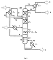
図1はエステル交換塔K1を示している。エステル交換塔K1には、2つの出発原料ストリーム、即ち、芳香族ヒドロキシ化合物を含有するストリーム2とジアルキルカーボネートを含有するストリーム1とが供給される。芳香族ヒドロキシ化合物を含有するストリーム2とジアルキルカーボネートを含有するストリーム1とは、反応領域RZの向流エステル化領域内に向流状態で案内されることによって、反応してアルキルアリールカーボネートおよび少量のジアリールカーボネートを形成する。
FIG. 1 shows a transesterification column K1. The transesterification column K1 is fed with two starting material streams:
特に連続処理の場合、ジアルキルカーボネートを含有するストリーム1は、ジアルキルカーボネートに加えて、芳香族ヒドロキシ化合物、反応で得られた脂肪族ヒドロキシ化合物R1−OHおよび/またはR2−OH(反応アルコール)、エステル交換で得られた微量のアルキルアリールカーボネートおよび/またはジアリールカーボネート、および反応により形成された不所望の副成分も部分的に含んで成る。ジアルキルカーボネートを含有するストリーム1は、例えば、0〜5重量%、好ましくは0.05〜3重量%および特に好ましくは0.05〜2重量%の反応アルコール、0〜40重量%、好ましくは0〜10重量%、特に好ましくは0〜5重量%の芳香族ヒドロキシ化合物、0〜5重量%のアルキルアリールカーボネート、0〜5重量%のジアリールカーボネートおよび0〜5重量%の反応で形成された他の副化合物(例えば、アルキルアリールエーテル)または出発原料中に既に含まれていた不純物を含んで成るものであってよい(いずれも、ジアルキルカーボネート含有ストリームの全重量を基準とする)。好ましくは、ジアルキルカーボネートを含有するストリーム1は、ジアルキルカーボネート含有ストリームの全重量基準で50〜100重量%のジアルキルカーボネートを有して成る(上記個々の成分を含めた合計は100重量%となる)。特に連続処理の場合、芳香族ヒドロキシ化合物を含有するストリーム2は、芳香族ヒドロキシ化合物に加えて、ジアルキルカーボネート、エステル交換で形成されたアルキルアリールカーボネートおよび/またはジアリールカーボネート、微量の反応アルコールおよび反応で得られた不所望の副生成物も部分的に含んで成る。例えば、ジアルキルカーボネートの含有量は0〜50重量%、反応アルコールの含有量は0〜10重量%、好ましくは0〜5重量%、アルキルアリールカーボネートおよびジアリールカーボネートの含有量は各々0〜10重量%、好ましくは0〜5重量%、および不所望の副生成物の含有量は0〜5重量%、好ましくは0〜1重量%であってよい(いずれも、芳香族ヒドロキシ化合物を含有するストリームの全重量を基準とする)。触媒を、芳香族ヒドロキシ化合物を含有するストリーム2と共にエステル交換塔へと付加的に供してもよい。かかる場合、触媒含有量は、芳香族ヒドロキシ化合物を含有するストリームの全重量基準で0〜5重量%であることが好ましい。芳香族ヒドロキシ化合物を含有するストリーム2は、芳香族ヒドロキシ化合物を含有するストリームの全重量基準で50〜100重量%の芳香族ヒドロキシ化合物を含有している(上記個々の成分を含めた合計は100重量%となる)。
In particular, in the case of continuous treatment, the stream 1 containing dialkyl carbonate contains, in addition to dialkyl carbonate, an aromatic hydroxy compound, an aliphatic hydroxy compound R 1 —OH and / or R 2 —OH (reactive alcohol) obtained by the reaction. , Partly also comprising traces of alkylaryl carbonates and / or diaryl carbonates obtained by transesterification and undesired subcomponents formed by the reaction. The stream 1 containing dialkyl carbonate is, for example, 0 to 5% by weight, preferably 0.05 to 3% by weight and particularly preferably 0.05 to 2% by weight of reactive alcohol, 0 to 40% by weight, preferably 0. 10% by weight, particularly preferably 0-5% by weight of aromatic hydroxy compounds, 0-5% by weight of alkylaryl carbonates, 0-5% by weight of diaryl carbonates and others formed by reaction of 0-5% by weight Secondary compounds (eg alkyl aryl ethers) or impurities already contained in the starting material (both based on the total weight of the dialkyl carbonate-containing stream). Preferably, stream 1 containing dialkyl carbonate comprises from 50 to 100% by weight of dialkyl carbonate based on the total weight of the dialkyl carbonate containing stream (the total including the individual components is 100% by weight). . Particularly in the case of continuous processing, the
塔K1に導入するに先立って、ジアルキルカーボネートを含有するストリーム1は、蒸発させ、場合によっては過熱状態にする。また、芳香族ヒドロキシ化合物を含有するストリーム2は、塔K1に導入するに先立って加熱する。出発原料ストリーム7および8は、それぞれ蒸発および場合によっては過熱させた後ならびに加熱の後に、互いに向流状態となるように反応領域RZへと案内される。換言すれば、芳香族ヒドロキシ化合物を含有するストリーム7は加熱された液体の形態で反応領域RZの上端側に供給される一方、ジアルキルカーボネートを含有するストリーム8は蒸気の形態または場合によっては僅かに過熱された形態で反応領域の下端側(底側)に供給される。反応で得られた脂肪族ヒドロキシ化合物R1−OHおよび/またはR2−OHは、気体の形態(13)で塔頂から未反応ジアルキルカーボネートと共に取り除かれる。容易に揮発しないアルキルアリールカーボネートは、塔K1の塔底(5)から、未反応の芳香族ヒドロキシ化合物、ジアリールカーボネートおよび場合によっては更に「容易に揮発しない化合物」と共に、液体ストリームの形態で除去される。所望の温度プロファイルを得るのに必要なエネルギーは、1以上のエバポレーターE1によって、特に塔のサンプにて得ることができる。そのために、ストリッピング部から流れてくる液体混合物(15)、あるいは、ストリッピング部が存在しない場合には反応領域から流れてくる液体混合物(15)が部分的に蒸発に付されることになる。エバポレーターの構造に左右されるが、蒸気のみまたは蒸気−液体混合物(ストリーム16)がエバポレーターの出口側で得られる。ストリーム16に含まれる蒸気はストリッピング部(AT)へと下方から供給される。あるいは、ストリッピング部が存在しない場合には、ストリーム16に含まれる蒸気は反応領域へと下方から供給される。更なる中間エバポレーターE2−ENによって反応領域へと熱を供給してもよい。反応領域RZとエバポレーターE1との間に設けられたストリッピング部ATでは、得られたアルキルアリールカーボネートおよびジアリールカーボネートの濃縮が行われる。尚、かかる塔K1のストリッピング部ATでは、ジアルキルカーボネートの消費に起因して、アルキルアリールカーボネートのジアリールカーボネートへの不均化反応が既に開始されており、ある程度促進された状態となっている。
Prior to introduction into column K1, stream 1 containing dialkyl carbonate is evaporated and possibly superheated. The
反応により形成された脂肪族ヒドロキシ化合物の濃縮および過剰のジアルキルカーボネートの濃縮は、コンデンサーC1と反応領域RZとの間に設けられた濃縮部で行われる。かかる濃縮時において、蒸留物4中の芳香族ヒドロキシ化合物の含有量は、0〜40重量%、好ましくは0〜10重量%、特に好ましくは0〜5重量%となる(蒸留物4の全重量基準)。濃縮部は少なくとも2つのセクションに分けられている。即ち、濃縮部は、中間コンデンサーC2を間に挟んで上方濃縮部VT2と下方濃縮部VT1とに分けられている。中間コンデンサーC2では、下方濃縮部VT1から上がってきた蒸気10の一部が凝縮される。中間コンデンサーC2に供される蒸気混合物10は、好ましくは、10〜70重量%の芳香族ヒドロキシ化合物を含有する。中間コンデンサーC2での凝縮温度は、芳香族ヒドロキシ化合物が比較的大量であることに起因して、塔頂コンデンサーC1での凝縮温度よりも相当に高くなっている。濃縮プロファイルの操作圧力および位置に依存するが、中間コンデンサーでの凝縮温度は、好ましくは100〜300℃、より好ましくは120〜250℃、更に好ましくは150〜240℃の範囲であり、また、塔頂コンデンサーでの凝縮温度は、好ましくは0〜250℃、より好ましくは40〜200℃の範囲である。中間凝縮C2で形成された凝縮物12およびその上の上方濃縮部VT2から流れてくる液体11は、下方濃縮部VT1へと案内される。中間コンデンサーの下流側の蒸気混合物は上方濃縮部VT2を通過することになる。上方濃縮部VT2から流れてくる蒸気13は、コンデンサーC1でできる限り凝縮され、凝縮物の一部が還流(14)として上方濃縮部VT2へと戻されたり、凝縮物の一部が蒸留物ストリーム4として除去されたりする。蒸留物ストリーム4は、実質的に過剰に使用されたジアルキルカーボネートおよび反応に起因して形成された対応する脂肪族ヒドロキシ化合物R1−OHおよび/またはR2−OH、および場合によっては更に少量の芳香族ヒドロキシ化合物を含有している。コンデンサーC1から得られる残留蒸気混合物は蒸気ストリーム3として除去する。
The concentration of the aliphatic hydroxy compound formed by the reaction and the concentration of the excess dialkyl carbonate are carried out in a concentration section provided between the condenser C1 and the reaction zone RZ. At the time of such concentration, the content of the aromatic hydroxy compound in the distillate 4 is 0 to 40% by weight, preferably 0 to 10% by weight, particularly preferably 0 to 5% by weight (the total weight of the distillate 4). Criteria). The concentration section is divided into at least two sections. That is, the concentration unit is divided into an upper concentration unit VT 2 and a lower concentration unit VT 1 with the intermediate condenser C 2 interposed therebetween. In the intermediate condenser C 2, a portion of the
中間コンデンサーC2で放出される凝縮熱は、本発明の方法に用いるために、上述したように直接的または間接的に本発明の方法のプロセスへと戻すことができる(図1に図示せず)。 Condensation heat released in the intermediate condenser C 2 is for use in the method of the present invention, not shown it can be returned to the process of directly or indirectly the process of the present invention as described above (in FIG. 1 ).
図2は本発明の方法の特に好ましい実施形態を示している。図2に示す実施態様では、中間コンデンサーが塔の外側に別個に構成されており、中間コンデンサーC2においてストリーム10の凝縮で得られた凝縮熱が、「エステル化塔K1の向流状態のエステル化に使用されることになるジアルキルカーボネート含有ストリーム1の蒸発」に使用される。それゆえ、ジアルキルカーボネート含有ストリーム1は蒸発ユニットC2へと供給されることによって、ジアルキルカーボネート含有ストリーム1を全体的または部分的に蒸発させ、場合によっては過熱状態に付す。下方濃縮部VT1の蒸気混合物10は中間コンデンサーC2へと供給され、部分的に凝縮に付される。これにより形成された凝縮物12は下側濃縮器VT1へと再度戻す一方、凝縮しなかった蒸気は上方濃縮部VT2へ供給する。その他の点では、図2に示す方法は図1に示す方法に相当している。従って、図1で行った説明が同様に適用される。
FIG. 2 shows a particularly preferred embodiment of the method of the invention. In the embodiment shown in FIG. 2, the intermediate condenser is separately configured outside the column, and the heat of condensation obtained in the condensation of the
更に、図3は本発明の方法の特に好ましい実施形態を示している。図3に示す態様では、中間コンデンサーC2および上方濃縮部VT2がエステル交換塔K1に一体化されておらず、塔K1の外側に別個に構成されている。下方濃縮部VT1から流れてくる蒸気混合物10は中間コンデンサーC2へと供給し、そこで部分的に凝縮させる。中間コンデンサーC2にて残留した蒸気は、別個の塔K2に収容されている上方濃縮部VT2へと供給する。上方濃縮部VT2から流れてくる液体11は、中間コンデンサーC2で得られる凝縮物12と共に、下方濃縮部へと供給する(12a)。上方濃縮部VT2から流れてくる蒸気13は、できる限り凝縮させ、得られた凝縮物の一部を上方濃縮部VT2へと還流(14)として戻し、別の一部を蒸留物ストリーム4として除去する。蒸留物ストリーム4は、実質的には、過剰に使用されたジアルキルカーボネートおよび反応で形成された対応する脂肪族ヒドロキシ化合物R1−OHおよび/またはR2−OH、ならびに場合によっては少量の芳香族ヒドロキシ化合物を含んで成る。コンデンサーC1から得られる残留蒸気混合物は、蒸気ストリーム3として除去する。その他の点では、図3に示す方法は図1に示す方法に相当している。従って、図1で行った説明が同様に適用される。
Furthermore, FIG. 3 shows a particularly preferred embodiment of the method of the invention. In the embodiment shown in FIG. 3, the intermediate condenser C 2 and the upper concentrating part VT 2 is not integrated in the transesterification column K1, it is separately configured on the outside of the tower K1. The
本発明の方法にとって好適な「少なくとも1つの中間コンデンサーを有して成るエステル交換塔」については、これまでにどの文献にも記載されていない。それゆえ、本発明では、ジアリールカーボネートおよび/またはアルキルアリールカーボネートが調製されるように、少なくとも1つのエステル交換触媒の存在下でジアルキルカーボネートと芳香族ヒドロキシ化合物とを反応させるための塔が更に提供される。
かかる本発明の塔は、
・ジアルキルカーボネート用の少なくとも1つの入口および芳香族ヒドロキシ化合物用の少なくとも1つの入口、
・塔の上方部分に設けられたガス状塔頂生成物用の少なくとも1つの出口、および、塔の下方部分に設けられた液状サンプ生成物用の少なくとも1つの出口、
・塔の上方部分に設けられた少なくとも1つの濃縮部(濃縮部は少なくとも2つのセクションを有する)および濃縮部の下方に設けられた少なくとも1つの反応領域
を有して成り、
少なくとも1つの濃縮部には少なくとも1つの中間コンデンサーが備えられている。
The “transesterification column comprising at least one intermediate condenser” suitable for the process of the present invention has not been described in any literature so far. Therefore, the present invention further provides a column for reacting a dialkyl carbonate with an aromatic hydroxy compound in the presence of at least one transesterification catalyst so that a diaryl carbonate and / or an alkyl aryl carbonate is prepared. The
Such a tower of the present invention comprises:
At least one inlet for dialkyl carbonate and at least one inlet for aromatic hydroxy compounds;
At least one outlet for the gaseous overhead product provided in the upper part of the tower and at least one outlet for the liquid sump product provided in the lower part of the tower;
Comprising at least one concentrating part provided in the upper part of the column (the concentrating part has at least two sections) and at least one reaction zone provided below the concentrating part;
At least one condensing part is provided with at least one intermediate condenser.
好ましくは、本発明のエステル交換塔は、反応領域にて400〜20000mmの直径DRZを有している(かかる反応領域は5000〜60000mmの長さLRZを有している)。また、本発明のエステル交換塔は、反応領域にて5〜50個と複数の理論段数nRZを有していることが好ましい。 Preferably, the transesterification column of the present invention, which has a diameter D RZ of 400~20000mm at reaction region (such a reaction region has a length L RZ of 5000~60000mm). Further, transesterification column of the present invention preferably has 5 to 50 and a plurality of theoretical stages n RZ in the reaction zone.
更に、反応領域は、複数の中間ヒータnEを有していてもよい。理論段数nRZに対する「反応領域における中間ヒータnEの数」の割合(比)は0〜2であることが好ましい。 Further, the reaction region may have a plurality of intermediate heaters n E. The ratio (ratio) of “the number of intermediate heaters n E in the reaction region” with respect to the theoretical plate number n RZ is preferably 0-2.
本発明のエステル交換塔は、場合によって設けられるストリッピング部の領域において、100〜20000mmの直径DATを有し、かかるストリッピング部が100〜20000mmの長さLATを有していることが好ましい。また好ましくは、本発明のエステル交換塔は、ストリッピング部にて、0〜20個の複数の理論段数nATを有している。 Transesterification column of the present invention, in the region of the stripping section which is provided by the case, has a diameter D AT of 100~20000Mm, it can take the stripping section has a length L AT of 100~20000Mm preferable. Also preferably, the transesterification column of the present invention, at the stripping section, and a 0-20 amino multiple theoretical stages n AT.
本発明のエステル交換塔の濃縮部は200〜10000mmの直径DVTを有していることが好ましい。上方濃縮部、下方濃縮部および中間コンデンサー(設けられる場合)を含んだ濃縮部の全領域は、100〜30000mm、好ましくは500〜30000mmの長さLVTを有している。また、濃縮部は、全部で2〜20の理論段nVTを有していることが好ましい。 Concentrating part of the transesterification column of the present invention preferably has a diameter D VT of 200~10000Mm. The entire region of the concentrating section including the upper concentrating section, the lower concentrating section and the intermediate condenser (if provided) has a length L VT of 100 to 30000 mm, preferably 500 to 30000 mm. Further, rectifying section preferably has a theoretical stage n VT total of 2 to 20.
好ましい実施形態では、本発明のエステル交換塔の下方濃縮部は、200〜10000mmの直径DVT1および200〜10000mmの長さLVT1を有している。また、好ましい実施形態では、本発明のエステル交換塔の上方濃縮部は、200〜10000mmの直径DVT2および200〜10000mmの長さLVT2を有している。反応領域における塔直径に対する下方濃縮部の直径の割合DVT1:DRZは0.3〜1であることが好ましい。反応領域における塔直径に対する上方濃縮部の直径の割合DVT2:DRZは0.1〜1であることが好ましい。 In a preferred embodiment, the lower concentrating part of the transesterification column of the present invention has a diameter D VT1 of 200-10000 mm and a length L VT1 of 200-10000 mm. Also in a preferred embodiment, the upper concentration of the transesterification column of the present invention has a diameter D VT2 and 200~10000Mm length L VT2 of 200~10000Mm. Ratio D of the diameter of the lower rectifying section for the column diameter in the reaction zone VT1: D RZ is preferably 0.3 to 1. The ratio D VT2 : D RZ of the diameter of the upper concentrated part to the tower diameter in the reaction zone is preferably 0.1-1.
更に好ましい実施形態では、本発明のエステル交換塔の中間コンデンサーは、100〜10000mmの長さLC2を有し、反応領域における塔直径に対する中間コンデンサーの直径の割合DC2:DRZは好ましくは0.1〜1である。また、中間コンデンサーは1〜5000m2の伝熱面積AC2を有していることが好ましい。 In a further preferred embodiment, the intermediate condenser of the transesterification column according to the invention has a length L C2 of 100 to 10000 mm and the ratio of the diameter of the intermediate condenser to the tower diameter in the reaction zone, D C2 : D RZ is preferably 0. .1-1. The intermediate condenser preferably has a heat transfer area A C2 of 1~5000m 2.
中間コンデンサーは、エステル交換塔に一体化させてもよいし、あるいは、エステル交換塔の外側にて別個の中間コンデンサー(中間凝縮器)の形態を成していてもよい。更には、中間コンデンサーおよび濃縮部の上側部分が、エステル交換塔に一体化しておらず、エステル交換塔の外側にて別個に設けてもよい。本発明では、中間コンデンサーは種々の構成・構造を有していてよく、例えば、プレート式熱交換器またはチューブ式熱交換器であってよい(かかる構成・構造は当業者には既知である)。 The intermediate condenser may be integrated into the transesterification column or may be in the form of a separate intermediate condenser (intermediate condenser) outside the transesterification column. Furthermore, the intermediate condenser and the upper part of the concentrating part are not integrated with the transesterification column, but may be provided separately outside the transesterification column. In the present invention, the intermediate condenser may have various configurations and structures, for example, a plate heat exchanger or a tube heat exchanger (such configurations and structures are known to those skilled in the art). .
上述した「本発明のエステル交換塔の寸法および特徴的データ」は、好ましくは、100kg/hよりも多い生成量について当てはまる(尚、ここでいう「生成量」とは、サンプ生成物に含まれているアルキルアリールカーボネートおよび/またはジアリールカーボネートの総量を意味するものと必要に応じて理解される)。当業者にとってみれば、上述の寸法をより少量の生成物用に変換する方法が分かるものである。従って、本発明では、かかる変換に起因して得られるエステル交換塔も提供される。 The above-mentioned “size and characteristic data of the transesterification column of the present invention” is preferably applied to a production amount of more than 100 kg / h (the “production amount” here is included in the sump product). Is understood as necessary to mean the total amount of alkylaryl carbonate and / or diaryl carbonate). One skilled in the art will know how to convert the above dimensions for a smaller amount of product. Accordingly, the present invention also provides a transesterification column obtained due to such conversion.
本発明の方法において第1のエステル交換塔について上述した好ましい範囲は、本発明の塔に対して適用される。 The preferred ranges described above for the first transesterification column in the process of the invention apply to the tower of the invention.
本発明の塔の特に好ましい実施形態の例は図1〜3に示している。 Examples of particularly preferred embodiments of the tower of the present invention are shown in FIGS.
以下の実施例は、本発明を例示するためのものであって、本発明を限定する意図はない。 The following examples are intended to illustrate the present invention and are not intended to limit the present invention.
実施例1(本発明の例)
−4個の理論段を有する上方濃縮部(VT2)、
−中間コンデンサー(C2)、
−4個の理論段を有する下方濃縮部(VT1)、
−30個の反応プレート(滞留量:12l)を有する反応領域(RZ)(3個の反応プレートは加熱要素を備えている)、および
−6個のプレート(滞留量:12l)を有するストリッピング部AT
を含むエステル交換塔において、
85.4重量%のフェノール、9.2重量%のジメチルカーボネート、3.2重量%のジフェニルカーボネート、1.5重量%のチタンテトラフェノレート、0.3重量%のアニソール、0.3重量%のメチルフェニルカーボネートおよび0.1重量%のメタノールの混合物を400kg/hで反応領域の上端に計量供給する。反応領域の底端では、98.8重量%のジメチルカーボネート、0.9重量%のフェノール、0.2重量%のアニソールおよび0.1重量%のメタノールの蒸気混合物を5℃過熱して539.6kg/hで供給する。
Example 1 (Example of the present invention)
-4 upper concentrating section (VT 2 ) with 4 theoretical plates,
- intermediate condenser (C 2),
-4 lower concentration section (VT 1 ) with 4 theoretical plates,
-Reaction zone (RZ) with 30 reaction plates (residence: 12 l) (3 reaction plates are equipped with heating elements), and stripping with -6 plates (residence: 12 l) Department AT
In a transesterification tower containing
85.4 wt% phenol, 9.2 wt% dimethyl carbonate, 3.2 wt% diphenyl carbonate, 1.5 wt% titanium tetraphenolate, 0.3 wt% anisole, 0.3 wt% A mixture of methyl phenyl carbonate and 0.1% by weight of methanol is metered into the top of the reaction zone at 400 kg / h. At the bottom end of the reaction zone, a steam mixture of 98.8% by weight dimethyl carbonate, 0.9% by weight phenol, 0.2% by weight anisole and 0.1% by weight methanol was heated to 5 ° C. to 539. Supply at 6 kg / h.
51重量%のフェノール、27.3重量%のMPC(124.7kg/h)、11.9重量%のDPC(54.3kg/h)、8.1重量%のDMC、0.4重量%のアニソールおよび1.3重量%のチタンテトラフェノレートからなる生成物の混合物456.9kg/hが塔のサンプにて得られる。 51 wt% phenol, 27.3 wt% MPC (124.7 kg / h), 11.9 wt% DPC (54.3 kg / h), 8.1 wt% DMC, 0.4 wt% A product mixture of 456.9 kg / h consisting of anisole and 1.3% by weight titanium tetraphenolate is obtained in the column sump.
エステル交換塔は、3.6barの上部圧力(VT2の上)および1.15の還流比で運転される。塔のサンプでは温度を230℃とし、反応領域では平均反応温度を215℃とする。反応領域のサンプ用エバポレーターE1および中間エバポレーターE2−ENは熱蒸気を用いて35barの蒸気圧力で運転させ、自然に再循環するエバポレーターをサンプ用エバポレーターE1として使用し、反応プレートに一体化されたダンピングレジスタを中間エバポレーターとして使用する。中間コンデンサーへの入口の温度は205℃であり、出口温度は193℃であり、冷却キャパシティは57kwである。中間コンデンサーで得られた凝縮熱を用いて、8barの熱蒸気圧力を有する熱蒸気(露点:170.4℃)を生成することができる。ジメチルカーボネート含有ストリームの蒸発に必要な加熱キャパシティは52kWである。ジメチルカーボネートの蒸発および過熱は135〜152℃の温度で行われ、この目的のために中間コンデンサーで使用された蒸気を容易に使用することができる。 The transesterification column is operated at an upper pressure of 3.6 bar (above VT 2 ) and a reflux ratio of 1.15. In the column sump, the temperature is 230 ° C and in the reaction zone the average reaction temperature is 215 ° C. Sump evaporator E 1 and intermediate evaporators E 2 -E N of the reaction zone is operated at a steam pressure of 35bar with hot steam, using an evaporator to re-circulate naturally as sump evaporator E 1, integrally to the reaction plate The damped damping register is used as an intermediate evaporator. The inlet temperature to the intermediate condenser is 205 ° C., the outlet temperature is 193 ° C., and the cooling capacity is 57 kw. The heat of condensation obtained in the intermediate condenser can be used to produce hot steam (dew point: 170.4 ° C.) with a hot steam pressure of 8 bar. The heating capacity required for evaporation of the dimethyl carbonate-containing stream is 52 kW. The evaporation and superheating of dimethyl carbonate takes place at a temperature of 135 to 152 ° C., and the steam used in the intermediate condenser for this purpose can easily be used.
中間コンデンサーC2の使用およびこれにより生成された廃熱の使用がなければ、エバポレーターE1およびE2−ENの加熱キャパシティを含め、ジメチルカーボネート含有ストリームの蒸発に必要なエステル交換のエネルギー消費量は183kWである。中間コンデンサーを使用することによって、52kW、すなわち28%の加熱キャパシティに関する節約が可能である。さらに、中間コンデンサーでは57kWの熱を移送することを考慮すれば、過剰の蒸気(5kW)をさらに生成させ、任意にこれを別の方面に使用することができる。上部コンデンサー(C1)での凝縮熱は126kWであり、137〜115℃の温度範囲で行われる。中間コンデンサーの使用がなければ、これは約183kWである。したがって、冷却キャパシティは中間コンデンサーを使用することによって著しく低減され、すなわち31%低減される。 The use and the use of the generated waste heat This intermediate condenser C 2 is not, including heating capacity of evaporator E 1 and E 2 -E N, energy consumption of the transesterification required for evaporation of the dimethyl carbonate-containing stream The amount is 183 kW. By using an intermediate condenser, a saving on heating capacity of 52 kW, ie 28%, is possible. In addition, considering the transfer of 57 kW of heat in the intermediate condenser, excess steam (5 kW) can be further generated and optionally used in other directions. The heat of condensation in the upper condenser (C1) is 126 kW, and is performed in a temperature range of 137 to 115 ° C. Without the use of an intermediate capacitor, this is about 183 kW. Thus, the cooling capacity is significantly reduced by using an intermediate condenser, i.e. 31%.
実施例2(本発明の例)
−6個の理論段を有する上方濃縮部(VT2)、
−中間コンデンサー(C2)、
−6個の理論段を有する下方濃縮部(VT1)、
−35個の反応プレート(滞留量:12l)を有する反応領域(RZ)(中間エバポレーターを有していない)、および
−9個のプレート(滞留量:12l)を有するストリッピング部(AT)
を含む塔において、
94.46重量%のフェノール、1.41重量%のジメチルカーボネート、2.75重量%のジフェニルカーボネート、1.3重量%のチタンテトラフェノレート、0.01重量%のアニソール、0.02重量%のメチルフェニルカーボネートおよび0.05重量%のメタノールの混合物を473.2kg/hで反応領域の上端に計量供給する。反応領域の底端では、98.3重量%のジメチルカーボネート、1.5重量%のフェノール、0.1重量%のアニソールおよび0.1重量%のメタノールからなる蒸気混合物を20℃過熱して477.4kg/hで供給する。
Example 2 (Example of the present invention)
An upper concentrating section (VT 2 ) having 6 theoretical plates,
- intermediate condenser (C 2),
A lower concentration section (VT 1 ) having 6 theoretical plates,
-Reaction zone (RZ) with 35 reaction plates (residence: 12 l) (without intermediate evaporator), and stripping section (AT) with -9 plates (residence: 12 l)
In a tower containing
94.46% by weight phenol, 1.41% by weight dimethyl carbonate, 2.75% by weight diphenyl carbonate, 1.3% by weight titanium tetraphenolate, 0.01% by weight anisole, 0.02% by weight A mixture of methyl phenyl carbonate and 0.05% by weight of methanol is metered into the top of the reaction zone at 473.2 kg / h. At the bottom end of the reaction zone, a steam mixture consisting of 98.3% by weight dimethyl carbonate, 1.5% by weight phenol, 0.1% by weight anisole and 0.1% by weight methanol is heated to 20 ° C. and heated to 477. .Supply at 4 kg / h.
69.18重量%のフェノール、6.32重量%のMPC(30.9kg/h)、23.03重量%のDPC(112.7kg/h)、0.2重量%のDMC、0.01重量%のアニソールおよび1.26重量%のチタンテトラフェノレートからなる生成物の混合物489.2kg/hが塔のサンプに得られる。 69.18 wt% phenol, 6.32 wt% MPC (30.9 kg / h), 23.03 wt% DPC (112.7 kg / h), 0.2 wt% DMC, 0.01 wt% 489.2 kg / h of a product mixture consisting of% anisole and 1.26% by weight titanium tetraphenolate is obtained in the column sump.
エステル交換塔は2barの上部圧力(VT2の上)および1.15の還流比で操作する。蒸留物中のフェノール含有量は2重量%であった。塔のサンプでは温度を227℃とし、反応領域では平均反応温度を200℃とする。サンプ用エバポレーターE1を熱蒸気を用いて35barの蒸気圧力で操作し、自然に再循環するエバポレーターをサンプ用エバポレーターE1として使用する。 The transesterification column operates at an upper pressure of 2 bar (above VT 2 ) and a reflux ratio of 1.15. The phenol content in the distillate was 2% by weight. In the column sump, the temperature is 227 ° C., and in the reaction zone the average reaction temperature is 200 ° C. The sump evaporator E 1 operated at steam pressure of 35bar using hot vapor, using an evaporator to re-circulate naturally as sump evaporator E 1.
中間コンデンサーへの入口の温度は190℃であり、出口温度は183℃であり、冷却キャパシティは46kwである。中間コンデンサーで形成された凝縮熱を用いて、8barの熱蒸気圧力を有する熱蒸気(露点:170.4℃)を生成することができる。ジメチルカーボネートの蒸発および過熱は122〜153℃の温度で行われ、この目的のために中間コンデンサーで使用された蒸気を容易に使用することができる。ジメチルカーボネート含有ストリームの蒸発に必要な加熱キャパシティは46kWである。 The inlet temperature to the intermediate condenser is 190 ° C., the outlet temperature is 183 ° C., and the cooling capacity is 46 kw. The heat of condensation formed in the intermediate condenser can be used to produce hot steam (dew point: 170.4 ° C.) with a hot steam pressure of 8 bar. The evaporation and superheating of dimethyl carbonate takes place at a temperature of 122-153 ° C., and the steam used in the intermediate condenser for this purpose can easily be used. The heating capacity required for evaporation of the dimethyl carbonate-containing stream is 46 kW.
中間コンデンサーC2の使用およびこれにより生成された廃熱の使用がなければ、エバポレーターE1およびE2−ENの加熱キャパシティを含め、ジメチルカーボネート含有ストリームの蒸発に必要なエステル交換のエネルギー消費量は190kWである。中間コンデンサーを使用することによって、46kW、すなわち24%の加熱キャパシティに関する節約が可能である。上部コンデンサー(C1)での凝縮熱は144kWであり、137〜115℃の温度範囲で行われる。中間コンデンサーの使用がなければ、これは約190kWである(比較例3参照)。したがって、冷却キャパシティは中間コンデンサーを使用することによって、著しく低減され、すなわち24%低減される。 The use and the use of the generated waste heat This intermediate condenser C 2 is not, including heating capacity of evaporator E 1 and E 2 -E N, energy consumption of the transesterification required for evaporation of the dimethyl carbonate-containing stream The amount is 190 kW. By using an intermediate condenser, a savings on heating capacity of 46 kW, ie 24%, is possible. The heat of condensation in the upper condenser (C1) is 144 kW, and is performed in a temperature range of 137 to 115 ° C. Without the use of an intermediate capacitor, this is about 190 kW (see Comparative Example 3). Thus, the cooling capacity is significantly reduced, i.e. reduced by 24%, by using an intermediate condenser.
比較例3
中間コンデンサーがないことを除けば実施例2と同じ条件下でエステル交換塔を運転した。蒸留物中のフェノール含有量2重量%を達成するために、還流比は2にまで上げねばならなかった。
Comparative Example 3
The transesterification column was operated under the same conditions as in Example 2 except that there was no intermediate condenser. In order to achieve a phenol content of 2% by weight in the distillate, the reflux ratio had to be increased to 2.
上部コンデンサーC1の冷却キャパシティは190kWであり、エバポレーターの冷却キャパシティは144kWであった。上部コンデンサーC1での凝縮は125〜97℃で行った。
上部コンデンサーでの凝縮が比較的低温レベルであるために、生じる凝縮熱はもはや多くのプロセスで使用することはできず、したがって、冷却水や空冷によって最終的に消失させねばならない。
The cooling capacity of the upper condenser C1 was 190 kW, and the cooling capacity of the evaporator was 144 kW. Condensation in the upper condenser C1 was performed at 125 to 97 ° C.
Because the condensation in the upper condenser is at a relatively low temperature level, the resulting heat of condensation can no longer be used in many processes and therefore must eventually be lost by cooling water or air cooling.
従って、本発明によれば、中間コンデンサーを有する構造によって、上部コンデンサーよりも高温レベルのエネルギーを塔内の材料ストリームから除去し、そのエネルギーを塔に供給されるストリームの蒸発に使用することができる。加えて多量のエネルギーの節約につながる。 Thus, according to the present invention, a structure having an intermediate condenser can remove a higher level of energy from the material stream in the tower than the upper condenser and use that energy to evaporate the stream fed to the tower. . In addition, a large amount of energy is saved.
上記で触れた全での文献は、全ての有用な目的のためにその全体を参照することによって本明細書に組み込まれる。 All documents mentioned above are hereby incorporated by reference in their entirety for all useful purposes.
本発明を具体化したある特定の構造を示して説明したものの、種々の変更および部品の再配列を本質的な本発明の概念および範囲から逸脱することなく行ってもよく、明細書で説明した特定の形態に限定されないことは当業者にとって明らかであろう。最後に、本願発明は下記の態様を有するものであることを確認的に述べておく:
[第1態様]少なくとも1つのジアルキルカーボネートおよび少なくとも1つの芳香族ヒドロキシ化合物から少なくとも1つのジアリールカーボネートもしくはアルキルアリールカーボネートまたはその混合物を調製する方法であって、
(a)少なくとも1つのエステル交換塔において、少なくとも1つのエステル交換触媒の存在下にてジアルキルカーボネートと芳香族ヒドロキシ化合物とを反応させること、ならびに、
(b)エステル交換塔の塔頂から蒸気を除去して、少なくとも1つのコンデンサーにて全体的または部分的に凝縮させること
を含んで成り、
エステル交換塔は、その上方部分に少なくとも1つの濃縮部(少なくとも2つのセクションを有している)および前記濃縮部の下方に少なくとも1つの反応領域を有して成り、
エステル交換塔の少なくとも1つの濃縮部には少なくとも1つの中間コンデンサーが備えられ、かかる中間コンデンサーで凝縮に起因して得られる凝縮熱が直接的または間接的に前記方法に戻される、方法。
[第2態様]エステル交換塔が、反応領域の下方に少なくとも1つのストリッピング部を有して成る、上記第1態様に記載の方法。
[第3態様]エステル交換塔の塔頂から除去された蒸気を凝縮することで得られた凝縮物の一部を還流としてエステル交換塔に戻す、上記第1態様に記載の方法。
[第4態様]得られた凝縮熱の全部または一部を、エステル交換塔に導入されるジアルキルカーボネートを蒸発させるのに直接的または間接的に用いる、上記第1態様に記載の方法。
[第5態様]中間コンデンサーが、エステル交換塔と一体化している又はエステル交換塔の外側にて別個の中間コンデンサーの形態を成している、上記第1態様に記載の方法。
[第6態様]少なくとも1つの中間コンデンサーが備えられているエステル交換塔の濃縮部が、中間コンデンサーの下方に設けられている下方濃縮部と、中間コンデンサーの上方に設けられている上方濃縮部とに分けられている、上記第1態様に記載の方法。
[第7態様]中間コンデンサーおよび上方濃縮部が、エステル交換塔と一体化している又はエステル交換塔の外側にて別個のデバイスの形態を成している、上記第6態様に記載の方法。
[第8態様]反応領域の温度が100〜300℃の範囲であって、反応領域の圧力が0.5〜20barの範囲である、上記第1態様に記載の方法。
[第9態様]反応領域の温度が120〜250℃の範囲であって、反応領域の圧力が0.8〜15barの範囲である、上記第7態様に記載の方法。
[第10態様]反応領域の温度が150〜240℃の範囲であって、反応領域の圧力が0.9〜10barの範囲である、上記第1態様に記載の方法。
[第11態様]ジアリールカーボネートが一般式(I)
[第12態様]R、R’およびR”がHである、上記第11態様に記載の方法。
[第13態様]ジアリールカーボネートがジフェニルカーボネートであって、ジアルキルカーボネートがジメチルカーボネートまたはジエチルカーボネートであって、芳香族ヒドロキシ化合物がフェノールである、上記第1態様に記載の方法。
[第14態様]ジアリールカーボネートおよび/またはアルキルアリールカーボネートが調製されるように、少なくとも1つのエステル交換触媒の存在下でジアルキルカーボネートと芳香族ヒドロキシ化合物とを反応させるための塔であって、
・ジアルキルカーボネート用の少なくとも1つの入口および芳香族ヒドロキシ化合物用の少なくとも1つの入口、
・塔の上方部分に設けられたガス状塔頂生成物用の少なくとも1つの出口、および、塔の下方部分に設けられた液状サンプ生成物用の少なくとも1つの出口、
・塔の上方部分に設けられた少なくとも1つの濃縮部(少なくとも2つのセクションを有している)および濃縮部の下方に設けられた少なくとも1つの反応領域
を有して成り、
少なくとも1つの濃縮部には少なくとも1つの中間コンデンサーが備えられている、塔。
[第15態様]塔が、反応領域の下方に少なくとも1つのストリッピング部を有している、上記第14態様に記載の塔。
[第16態様]少なくとも1つの中間コンデンサーを備えた濃縮部が、中間コンデンサーの下方に設けられている下方濃縮部と、中間コンデンサーの上方に設けられている上方濃縮部とに分けられている、上記第14態様に記載の塔。
[第17態様]中間コンデンサーおよび必要に応じて設けられる上方濃縮部が塔と一体化している又は塔の外側にて別個のデバイスの形態を成している、上記第14態様に記載の塔。
[第18態様]エステル交換塔の反応領域が3〜50の理論段を有する、上記第14態様に記載の塔。
[第19態様]エステル交換塔の反応領域が10〜40の理論段を有する、上記第14態様に記載の塔。
While a particular structure embodying the invention has been shown and described, various modifications and rearrangements of parts may be made without departing from the essential concept and scope of the invention, as described in the specification. It will be apparent to those skilled in the art that the present invention is not limited to a particular form. Finally, it should be noted that the present invention has the following aspects:
[First Embodiment] A method for preparing at least one diaryl carbonate or alkylaryl carbonate or a mixture thereof from at least one dialkyl carbonate and at least one aromatic hydroxy compound,
(A) reacting a dialkyl carbonate and an aromatic hydroxy compound in the presence of at least one transesterification catalyst in at least one transesterification column; and
(B) removing the vapor from the top of the transesterification column and condensing it entirely or partially in at least one condenser;
Comprising
The transesterification column comprises at least one concentrating part (having at least two sections) in the upper part thereof and at least one reaction zone below the concentrating part,
A process wherein at least one condensing section of the transesterification column is provided with at least one intermediate condenser, in which the heat of condensation obtained due to condensation is returned directly or indirectly to the process.
[Second Embodiment] The method according to the first embodiment, wherein the transesterification column has at least one stripping section below the reaction zone.
[Third embodiment] The method according to the first embodiment, wherein a part of the condensate obtained by condensing the vapor removed from the top of the transesterification column is returned to the transesterification column as reflux.
[Fourth Embodiment] The method according to the first embodiment, wherein all or part of the heat of condensation obtained is used directly or indirectly to evaporate the dialkyl carbonate introduced into the transesterification column.
[Fifth Aspect] The method according to the first aspect, wherein the intermediate condenser is integrated with the transesterification tower or is in the form of a separate intermediate condenser outside the transesterification tower.
[Sixth aspect] The concentrating part of the transesterification column provided with at least one intermediate condenser comprises: a lower concentrating part provided below the intermediate condenser; an upper concentrating part provided above the intermediate condenser; The method according to the first aspect, which is divided into:
[Seventh Aspect] The method according to the sixth aspect, wherein the intermediate condenser and the upper concentrating part are integrated with the transesterification column or are formed as separate devices outside the transesterification column.
[Eighth Aspect] The method according to the first aspect, wherein the temperature in the reaction zone is in the range of 100 to 300 ° C. and the pressure in the reaction zone is in the range of 0.5 to 20 bar.
[Ninth Embodiment] The method according to the seventh embodiment, wherein the temperature in the reaction zone is in the range of 120 to 250 ° C. and the pressure in the reaction zone is in the range of 0.8 to 15 bar.
[Tenth embodiment] The method according to the first embodiment, wherein the temperature in the reaction zone is in the range of 150 to 240 ° C and the pressure in the reaction zone is in the range of 0.9 to 10 bar.
[Eleventh Embodiment] The diaryl carbonate is represented by the general formula (I)
[Twelfth Embodiment] The method according to the eleventh embodiment, wherein R, R ′ and R ″ are H.
[Thirteenth Embodiment] The method according to the first embodiment, wherein the diaryl carbonate is diphenyl carbonate, the dialkyl carbonate is dimethyl carbonate or diethyl carbonate, and the aromatic hydroxy compound is phenol.
[14th embodiment] A tower for reacting a dialkyl carbonate and an aromatic hydroxy compound in the presence of at least one transesterification catalyst so that a diaryl carbonate and / or an alkylaryl carbonate is prepared,
At least one inlet for dialkyl carbonate and at least one inlet for aromatic hydroxy compounds;
At least one outlet for the gaseous overhead product provided in the upper part of the tower and at least one outlet for the liquid sump product provided in the lower part of the tower;
At least one concentrating part (having at least two sections) provided in the upper part of the column and at least one reaction region provided below the concentrating part
Comprising
A tower, wherein at least one concentrating part is provided with at least one intermediate condenser.
[Fifteenth aspect] The tower according to the fourteenth aspect, wherein the tower has at least one stripping section below the reaction zone.
[Sixteenth aspect] The concentrating section having at least one intermediate condenser is divided into a lower concentrating section provided below the intermediate condenser and an upper concentrating section provided above the intermediate condenser. The tower according to the fourteenth aspect.
[Seventeenth aspect] The tower according to the fourteenth aspect, wherein the intermediate condenser and the upper concentrating portion provided as necessary are integrated with the tower or form a separate device outside the tower.
[18th aspect] The tower according to the 14th aspect, wherein the reaction zone of the transesterification column has 3 to 50 theoretical plates.
[Nineteenth aspect] The tower according to the fourteenth aspect, wherein the reaction zone of the transesterification column has 10 to 40 theoretical plates.
本願は2007年5月25日に出願されたドイツ特許出願第10 2007 024574号の利益を主張する。ドイツ特許出願第10 2007 024574号公報およびそこに示されている文献は、全て有用な目的のために、その全体を参照することによって本願明細書に組み込まれる。 The present application claims the benefit of German Patent Application No. 10 2007 024574, filed May 25, 2007. German Patent Application No. 10 2007 024574 and the literature indicated therein are hereby incorporated by reference in their entirety for all useful purposes.
K1 エステル交換塔
K2 別個にされた濃縮部を備えた塔
C1 コンデンサー
C2 中間コンデンサー
VT1 下方濃縮部
VT2 上方濃縮部
RZ 反応領域
AT ストリッピング部
E1 サンプ生成物用のエバポレーター
E2−EN 反応領域の中間エバポレーター
図1〜3で示されているストリーム:
1 ジアルキルカーボネートを含有するストリーム(液体)
2 芳香族ヒドロキシ化合物を含有するストリーム
3 コンデンサーC1での凝縮後の残留蒸気混合物
4 コンデンサーC1での凝縮後のエステル交換塔の蒸留物
5 サンプ用エバポレーターE1での濃縮後に得られるエステル交換塔のサンプ生成物
6 加熱後の芳香族ヒドロキシ化合物を含有するストリーム
7 蒸発(場合によっては更に過熱)後のジアルキルカーボネートを含有するストリーム
8 中間コンデンサーC2の下流の蒸気混合物
9 中間コンデンサーC2への蒸気混合物
10 上方濃縮部VT2を出た液体
11 中間コンデンサーC2の凝縮物
12 コンデンサーC1への蒸気混合物
12a 下方濃縮部VT1への液体
13 上方濃縮部VT2への戻り
14 ストリッピング部ATからの液体混合物の流れ
15 エバポレーターE1の出口での蒸気/液体混合物
Tower equipped with a rectifying section which is in K1 transesterification column K2 separately C1 capacitor C 2 intermediate condenser VT 1 lower concentrating part VT 2 upper rectifying section RZ reaction zone AT stripping section evaporator E 2 -E for E 1 sump product Intermediate evaporator in N reaction zone
Streams shown in FIGS. 1-3:
1 Stream containing dialkyl carbonate (liquid)
Containing 2 aromatic hydroxy compound stream 3 a residual vapor mixture 4 transesterification column obtained after concentration in
Claims (4)
(a)少なくとも1つのエステル交換塔において、少なくとも1つのエステル交換触媒の存在下にてジアルキルカーボネートと芳香族ヒドロキシ化合物とを反応させること、ならびに、
(b)エステル交換塔の塔頂から蒸気を除去して、少なくとも1つのコンデンサーにて全体的または部分的に凝縮させること
を含んで成り、
エステル交換塔は、その上方部分に少なくとも1つの濃縮部(少なくとも2つのセクションを有している)および前記濃縮部の下方に少なくとも1つの反応領域を有して成り、
エステル交換塔の少なくとも1つの濃縮部には少なくとも1つの中間コンデンサーが備えられ、少なくとも1つの中間コンデンサーが備えられているエステル交換塔の濃縮部が、中間コンデンサーの下方に設けられている下方濃縮部と、中間コンデンサーの上方に設けられている上方濃縮部とに分けられており、かかる中間コンデンサーで凝縮に起因して得られる凝縮熱が直接的または間接的に前記方法に戻される、方法。 A process for preparing at least one diaryl carbonate or alkylaryl carbonate or a mixture thereof from at least one dialkyl carbonate and at least one aromatic hydroxy compound, comprising:
(A) reacting a dialkyl carbonate and an aromatic hydroxy compound in the presence of at least one transesterification catalyst in at least one transesterification column; and
(B) removing the vapor from the top of the transesterification column and condensing in whole or in part in at least one condenser;
The transesterification column comprises at least one concentrating part (having at least two sections) in the upper part thereof and at least one reaction zone below the concentrating part,
The at least one concentrating part of the transesterification column is provided with at least one intermediate condenser, and the concentrating part of the transesterification tower provided with at least one intermediate condenser is provided below the intermediate condenser. And an upper concentrating part provided above the intermediate condenser, and the condensation heat obtained by condensation in the intermediate condenser is directly or indirectly returned to the method.
・ジアルキルカーボネート用の少なくとも1つの入口および芳香族ヒドロキシ化合物用の少なくとも1つの入口、
・塔の上方部分に設けられたガス状塔頂生成物用の少なくとも1つの出口、および、塔の下方部分に設けられた液状サンプ生成物用の少なくとも1つの出口、
・塔の上方部分に設けられた少なくとも1つの濃縮部(少なくとも2つのセクションを有している)および濃縮部の下方に設けられた少なくとも1つの反応領域
を有して成り、
少なくとも1つの濃縮部には少なくとも1つの中間コンデンサーが備えられている、塔。 A column for reacting a dialkyl carbonate and an aromatic hydroxy compound in the presence of at least one transesterification catalyst such that a diaryl carbonate and / or an alkylaryl carbonate is prepared,
At least one inlet for dialkyl carbonate and at least one inlet for aromatic hydroxy compounds;
At least one outlet for the gaseous overhead product provided in the upper part of the tower and at least one outlet for the liquid sump product provided in the lower part of the tower;
Comprising at least one concentrating part (having at least two sections) provided in the upper part of the column and at least one reaction region provided below the concentrating part,
A tower, wherein at least one concentrating part is provided with at least one intermediate condenser.
Applications Claiming Priority (2)
| Application Number | Priority Date | Filing Date | Title |
|---|---|---|---|
| DE102007024574 | 2007-05-25 | ||
| DE102007024574.4 | 2007-05-25 |
Publications (3)
| Publication Number | Publication Date |
|---|---|
| JP2009051814A JP2009051814A (en) | 2009-03-12 |
| JP2009051814A5 JP2009051814A5 (en) | 2011-06-30 |
| JP5580970B2 true JP5580970B2 (en) | 2014-08-27 |
Family
ID=39731483
Family Applications (1)
| Application Number | Title | Priority Date | Filing Date |
|---|---|---|---|
| JP2008135361A Expired - Fee Related JP5580970B2 (en) | 2007-05-25 | 2008-05-23 | Method for preparing diaryl carbonate or arylalkyl carbonate from dialkyl carbonate |
Country Status (8)
| Country | Link |
|---|---|
| US (2) | US8003817B2 (en) |
| EP (1) | EP1995233A3 (en) |
| JP (1) | JP5580970B2 (en) |
| KR (1) | KR20080103924A (en) |
| CN (1) | CN101311161A (en) |
| RU (1) | RU2480448C2 (en) |
| SG (1) | SG148127A1 (en) |
| TW (1) | TWI412516B (en) |
Families Citing this family (4)
| Publication number | Priority date | Publication date | Assignee | Title |
|---|---|---|---|---|
| DE102008029514A1 (en) * | 2008-06-21 | 2009-12-24 | Bayer Materialscience Ag | Process for the preparation of diaryl carbonates from dialkyl carbonates |
| DE102009053370A1 (en) * | 2009-11-14 | 2011-05-19 | Bayer Materialscience Ag | Process for the purification of dialkyl carbonates |
| WO2013086016A2 (en) * | 2011-12-07 | 2013-06-13 | Shell Oil Company | A process for producing aromatic carbonates |
| EP2711353B1 (en) | 2012-09-20 | 2018-10-31 | SABIC Global Technologies B.V. | Process for the continuous manufacture of aryl alkyl carbonate and diaryl carbonate using vapor recompression |
Family Cites Families (44)
| Publication number | Priority date | Publication date | Assignee | Title |
|---|---|---|---|---|
| DE258412C (en) | 1911-11-14 | |||
| US3642858A (en) | 1969-02-12 | 1972-02-15 | Dow Chemical Co | Carbonate synthesis from alkylene carbonates |
| GB1310514A (en) * | 1969-07-02 | 1973-03-21 | Bligh B R | Process of contunuous distillation |
| US3803201A (en) | 1971-02-22 | 1974-04-09 | Dow Chemical Co | Synthesis of dimethyl carbonate |
| DE2736063A1 (en) * | 1977-08-10 | 1979-02-22 | Bayer Ag | Process for the preparation of aromatic carbonic acid esters |
| DE2736062A1 (en) | 1977-08-10 | 1979-02-22 | Bayer Ag | Process for the preparation of aromatic carbonic acid esters |
| DE2740243A1 (en) * | 1977-09-07 | 1979-03-15 | Bayer Ag | PROCESS FOR THE PRODUCTION OF DIALKYLCARBONATES |
| JPS5463023A (en) | 1977-10-26 | 1979-05-21 | Mitsubishi Chem Ind Ltd | Ester exchange of carbonate |
| JPS54125617A (en) | 1978-03-20 | 1979-09-29 | Mitsubishi Chem Ind Ltd | Ester interchange of carbonate |
| DE3017419A1 (en) * | 1980-05-07 | 1981-11-12 | Bayer Ag, 5090 Leverkusen | METHOD FOR PRODUCING AROMATIC POLYCARBONATES |
| JPS57176932A (en) | 1981-04-24 | 1982-10-30 | Asahi Chem Ind Co Ltd | Preparation of carbonic acid ester |
| US4554110A (en) | 1983-12-27 | 1985-11-19 | General Electric Company | Process for the preparation of aromatic carbonates |
| US4552704A (en) * | 1983-12-27 | 1985-11-12 | General Electric Company | Process for the production of aromatic carbonates |
| JPH06725B2 (en) | 1985-01-29 | 1994-01-05 | ダイセル化学工業株式会社 | Method for producing diphenyl carbonate |
| DE3809417A1 (en) | 1988-03-21 | 1989-10-12 | Henkel Kgaa | METHOD FOR CONTINUOUSLY Esterifying Fatty Acids |
| DD258412A1 (en) | 1987-03-12 | 1988-07-20 | Harzer Gipswerke Rottleberode | CONDENSER FOR HYDROPHOBIC GAS MIXTURES |
| JPH0710314B2 (en) | 1987-06-26 | 1995-02-08 | ジューキ株式会社 | Vertical feed amount control device for sewing machine |
| JPH07100713B2 (en) | 1987-10-02 | 1995-11-01 | 財団法人相模中央化学研究所 | 14-fluoro anthracycline derivative |
| JPH0193560A (en) | 1987-10-05 | 1989-04-12 | Asahi Chem Ind Co Ltd | Production of diaryl carbonate |
| US5034557A (en) | 1988-04-16 | 1991-07-23 | Mitsui Petrochemical Industries, Ltd. | Process for production of aromatic carbonate compound |
| EP0461274B1 (en) | 1989-12-28 | 1994-06-15 | Asahi Kasei Kogyo Kabushiki Kaisha | Process for continuously producing aromatic carbonate |
| DE4006420C5 (en) | 1990-03-01 | 2004-02-05 | Robert Bosch Gmbh | Device for optically detecting foreign bodies or a coating on the surface of an optically transparent pane |
| DE4006520A1 (en) | 1990-03-02 | 1991-09-05 | Bayer Ag | Di:aryl or alkyl carbonate prodn. from alkyl carbonate - using polymeric hydroxy-stannoxane as ester exchange catalyst for high activity and selectivity |
| DE4036594A1 (en) | 1990-11-16 | 1992-05-21 | Bayer Ag | METHOD FOR PRODUCING AROMATIC CARBONIC DIESTERS |
| DE4226756A1 (en) | 1992-08-13 | 1994-02-17 | Bayer Ag | Process for the production of dicarbonates |
| DE4226755A1 (en) * | 1992-08-13 | 1994-02-17 | Bayer Ag | Process for the continuous production of diaryl carbonates from dialkyl carbonates |
| JPH07304713A (en) * | 1994-05-10 | 1995-11-21 | Nippon Shokubai Co Ltd | Production of aromatic carbonic acid ester |
| JP3571761B2 (en) * | 1994-06-09 | 2004-09-29 | 出光石油化学株式会社 | Method for producing diphenyl carbonate |
| JP3846926B2 (en) | 1995-12-27 | 2006-11-15 | 日本ジーイープラスチックス株式会社 | Process for continuous production of aromatic carbonates |
| US5731453A (en) * | 1996-03-12 | 1998-03-24 | Ube Industries, Ltd. | Process for producing a diaryl carbonate |
| CN2314840Y (en) * | 1997-07-15 | 1999-04-21 | 清华大学 | Novel catalytic rectifying tower |
| US6093842A (en) * | 1998-09-25 | 2000-07-25 | General Electric Company | Process for continuous production of carbonate esters |
| JP2001093560A (en) | 1999-09-27 | 2001-04-06 | Kashimakita Kyodo Hatsuden Kk | Redox (reduction-oxidation) flow battery |
| US6294684B1 (en) * | 1999-12-08 | 2001-09-25 | General Electric Company | Method and apparatus for the continuous production of diaryl carbonates |
| US6515187B1 (en) * | 2001-10-03 | 2003-02-04 | Atofina Chemicals, Inc. | Process for recovering acrolein or propionaldehyde from dilute aqueous streams |
| EP1480939B1 (en) * | 2002-02-05 | 2015-12-23 | LG Chem, Ltd. | Continuous method for preparing aromatic carbonate using a heterogeneous catalyst and a reaction apparatus for the same |
| JP2004063023A (en) | 2002-07-30 | 2004-02-26 | Renesas Technology Corp | Semiconductor storage device |
| AU2003255152A1 (en) | 2002-08-12 | 2004-03-03 | Mitsubishi Chemical Corporation | Process for producing aromatic carbonate |
| CN1247289C (en) * | 2002-08-27 | 2006-03-29 | 中国石油化工股份有限公司 | Catalytic careful distillation intermediate extraction new technology |
| US7652122B2 (en) * | 2003-06-27 | 2010-01-26 | Asahi Kasei Chemicals Corporation | Method for producing an aromatic carbonate |
| CN1247520C (en) * | 2004-03-25 | 2006-03-29 | 华中科技大学 | Technique and equipment for synthesizing diaryl carbonate through catalyzing rectification |
| BRPI0512524A (en) | 2004-06-25 | 2008-03-11 | Asahi Kasei Chemicals Corp | process for the production of an aromatic carbonate, process for the industrial production thereof, aromatic carbonate, and continuous multi-stage distillation column |
| EA010579B1 (en) * | 2004-09-27 | 2008-10-30 | Асахи Касеи Кемикалз Корпорейшн | Process for producing aromatic carbonate on commercial scale |
| US7288668B2 (en) * | 2005-11-17 | 2007-10-30 | Catalytic Distillation Technologies | Process for making diaryl carbonate |
-
2008
- 2008-05-10 EP EP08008796A patent/EP1995233A3/en not_active Withdrawn
- 2008-05-16 US US12/121,873 patent/US8003817B2/en not_active Expired - Fee Related
- 2008-05-22 SG SG200803860-6A patent/SG148127A1/en unknown
- 2008-05-22 CN CNA2008100985756A patent/CN101311161A/en active Pending
- 2008-05-23 RU RU2008120393/04A patent/RU2480448C2/en not_active IP Right Cessation
- 2008-05-23 KR KR1020080048073A patent/KR20080103924A/en not_active Application Discontinuation
- 2008-05-23 JP JP2008135361A patent/JP5580970B2/en not_active Expired - Fee Related
- 2008-05-23 TW TW097118986A patent/TWI412516B/en not_active IP Right Cessation
-
2011
- 2011-05-06 US US13/102,255 patent/US20110206568A1/en not_active Abandoned
Also Published As
| Publication number | Publication date |
|---|---|
| TW200911750A (en) | 2009-03-16 |
| CN101311161A (en) | 2008-11-26 |
| SG148127A1 (en) | 2008-12-31 |
| EP1995233A3 (en) | 2010-06-02 |
| US20110206568A1 (en) | 2011-08-25 |
| KR20080103924A (en) | 2008-11-28 |
| RU2480448C2 (en) | 2013-04-27 |
| EP1995233A2 (en) | 2008-11-26 |
| JP2009051814A (en) | 2009-03-12 |
| US8003817B2 (en) | 2011-08-23 |
| TWI412516B (en) | 2013-10-21 |
| US20080293960A1 (en) | 2008-11-27 |
| RU2008120393A (en) | 2009-11-27 |
Similar Documents
| Publication | Publication Date | Title |
|---|---|---|
| US8039659B2 (en) | Processes for preparing diaryl and/or alkylaryl carbonates from dialkyl carbonates | |
| JP4292210B2 (en) | Industrial production method of high purity diphenyl carbonate | |
| US9040732B2 (en) | Process for preparing diaryl carbonates from dialkyl carbonates | |
| US8952189B2 (en) | Process for preparing diaryl carbonates or alkyl aryl carbonates from dialkyl carbonates | |
| TWI582072B (en) | Process for purifying dialkyl carbonates | |
| JP5362331B2 (en) | Method for purifying diaryl carbonate | |
| JP4236205B2 (en) | Industrial production of high purity diphenyl carbonate | |
| JP5580970B2 (en) | Method for preparing diaryl carbonate or arylalkyl carbonate from dialkyl carbonate | |
| KR20110090827A (en) | Process for preparing dialkyl carbonates | |
| EP2711353B1 (en) | Process for the continuous manufacture of aryl alkyl carbonate and diaryl carbonate using vapor recompression |
Legal Events
| Date | Code | Title | Description |
|---|---|---|---|
| A521 | Written amendment |
Free format text: JAPANESE INTERMEDIATE CODE: A523 Effective date: 20110512 |
|
| A621 | Written request for application examination |
Free format text: JAPANESE INTERMEDIATE CODE: A621 Effective date: 20110512 |
|
| A977 | Report on retrieval |
Free format text: JAPANESE INTERMEDIATE CODE: A971007 Effective date: 20130425 |
|
| A131 | Notification of reasons for refusal |
Free format text: JAPANESE INTERMEDIATE CODE: A131 Effective date: 20130507 |
|
| A601 | Written request for extension of time |
Free format text: JAPANESE INTERMEDIATE CODE: A601 Effective date: 20130806 |
|
| A602 | Written permission of extension of time |
Free format text: JAPANESE INTERMEDIATE CODE: A602 Effective date: 20130809 |
|
| A601 | Written request for extension of time |
Free format text: JAPANESE INTERMEDIATE CODE: A601 Effective date: 20130906 |
|
| A602 | Written permission of extension of time |
Free format text: JAPANESE INTERMEDIATE CODE: A602 Effective date: 20130911 |
|
| TRDD | Decision of grant or rejection written | ||
| A01 | Written decision to grant a patent or to grant a registration (utility model) |
Free format text: JAPANESE INTERMEDIATE CODE: A01 Effective date: 20140617 |
|
| A61 | First payment of annual fees (during grant procedure) |
Free format text: JAPANESE INTERMEDIATE CODE: A61 Effective date: 20140714 |
|
| R150 | Certificate of patent or registration of utility model |
Ref document number: 5580970 Country of ref document: JP Free format text: JAPANESE INTERMEDIATE CODE: R150 |
|
| LAPS | Cancellation because of no payment of annual fees |