EP2062638A1 - Exhaust gas purification apparatus - Google Patents
Exhaust gas purification apparatus Download PDFInfo
- Publication number
- EP2062638A1 EP2062638A1 EP08167643A EP08167643A EP2062638A1 EP 2062638 A1 EP2062638 A1 EP 2062638A1 EP 08167643 A EP08167643 A EP 08167643A EP 08167643 A EP08167643 A EP 08167643A EP 2062638 A1 EP2062638 A1 EP 2062638A1
- Authority
- EP
- European Patent Office
- Prior art keywords
- exhaust gas
- cathode
- electrochemical device
- anode
- purification apparatus
- Prior art date
- Legal status (The legal status is an assumption and is not a legal conclusion. Google has not performed a legal analysis and makes no representation as to the accuracy of the status listed.)
- Withdrawn
Links
Images


Classifications
-
- B—PERFORMING OPERATIONS; TRANSPORTING
- B01—PHYSICAL OR CHEMICAL PROCESSES OR APPARATUS IN GENERAL
- B01D—SEPARATION
- B01D53/00—Separation of gases or vapours; Recovering vapours of volatile solvents from gases; Chemical or biological purification of waste gases, e.g. engine exhaust gases, smoke, fumes, flue gases, aerosols
- B01D53/34—Chemical or biological purification of waste gases
- B01D53/92—Chemical or biological purification of waste gases of engine exhaust gases
- B01D53/922—Mixtures of carbon monoxide or hydrocarbons and nitrogen oxides
- B01D53/925—Simultaneous elimination of carbon monoxide or hydrocarbons and nitrogen oxides
-
- B—PERFORMING OPERATIONS; TRANSPORTING
- B01—PHYSICAL OR CHEMICAL PROCESSES OR APPARATUS IN GENERAL
- B01D—SEPARATION
- B01D53/00—Separation of gases or vapours; Recovering vapours of volatile solvents from gases; Chemical or biological purification of waste gases, e.g. engine exhaust gases, smoke, fumes, flue gases, aerosols
- B01D53/32—Separation of gases or vapours; Recovering vapours of volatile solvents from gases; Chemical or biological purification of waste gases, e.g. engine exhaust gases, smoke, fumes, flue gases, aerosols by electrical effects other than those provided for in group B01D61/00
- B01D53/326—Separation of gases or vapours; Recovering vapours of volatile solvents from gases; Chemical or biological purification of waste gases, e.g. engine exhaust gases, smoke, fumes, flue gases, aerosols by electrical effects other than those provided for in group B01D61/00 in electrochemical cells
-
- F—MECHANICAL ENGINEERING; LIGHTING; HEATING; WEAPONS; BLASTING
- F01—MACHINES OR ENGINES IN GENERAL; ENGINE PLANTS IN GENERAL; STEAM ENGINES
- F01N—GAS-FLOW SILENCERS OR EXHAUST APPARATUS FOR MACHINES OR ENGINES IN GENERAL; GAS-FLOW SILENCERS OR EXHAUST APPARATUS FOR INTERNAL-COMBUSTION ENGINES
- F01N3/00—Exhaust or silencing apparatus having means for purifying, rendering innocuous, or otherwise treating exhaust
- F01N3/08—Exhaust or silencing apparatus having means for purifying, rendering innocuous, or otherwise treating exhaust for rendering innocuous
- F01N3/0892—Electric or magnetic treatment, e.g. dissociation of noxious components
-
- B—PERFORMING OPERATIONS; TRANSPORTING
- B01—PHYSICAL OR CHEMICAL PROCESSES OR APPARATUS IN GENERAL
- B01D—SEPARATION
- B01D2257/00—Components to be removed
- B01D2257/40—Nitrogen compounds
- B01D2257/404—Nitrogen oxides other than dinitrogen oxide
-
- B—PERFORMING OPERATIONS; TRANSPORTING
- B01—PHYSICAL OR CHEMICAL PROCESSES OR APPARATUS IN GENERAL
- B01D—SEPARATION
- B01D2258/00—Sources of waste gases
- B01D2258/01—Engine exhaust gases
- B01D2258/012—Diesel engines and lean burn gasoline engines
-
- B—PERFORMING OPERATIONS; TRANSPORTING
- B01—PHYSICAL OR CHEMICAL PROCESSES OR APPARATUS IN GENERAL
- B01D—SEPARATION
- B01D2259/00—Type of treatment
- B01D2259/80—Employing electric, magnetic, electromagnetic or wave energy, or particle radiation
- B01D2259/818—Employing electrical discharges or the generation of a plasma
-
- F—MECHANICAL ENGINEERING; LIGHTING; HEATING; WEAPONS; BLASTING
- F01—MACHINES OR ENGINES IN GENERAL; ENGINE PLANTS IN GENERAL; STEAM ENGINES
- F01N—GAS-FLOW SILENCERS OR EXHAUST APPARATUS FOR MACHINES OR ENGINES IN GENERAL; GAS-FLOW SILENCERS OR EXHAUST APPARATUS FOR INTERNAL-COMBUSTION ENGINES
- F01N2240/00—Combination or association of two or more different exhaust treating devices, or of at least one such device with an auxiliary device, not covered by indexing codes F01N2230/00 or F01N2250/00, one of the devices being
- F01N2240/32—Combination or association of two or more different exhaust treating devices, or of at least one such device with an auxiliary device, not covered by indexing codes F01N2230/00 or F01N2250/00, one of the devices being a fuel cell
Definitions
- the present invention relates to an exhaust gas purification apparatus.
- Some exhaust gas purification apparatuses which decompose harmful components present in exhaust gas generated by vehicle internal combustion engines and the like, are provided with electrochemical devices that promote a chemical reaction by utilizing ion conduction by electrolytes. Such electrochemical devices are also referred to as electrochemical reactors.
- Electrochemical devices have electrolytes between an anode and a cathode, and the properties of these electrochemical devices are influenced by the conduction properties of these electrolytes.
- materials used as electrolytes include solid oxide-based materials (such as yttria-stabilized zirconia (YSZ)) and phosphoric acid-based materials.
- FIG. 5 shows an operating principle of an exhaust gas purification apparatus using a conventional electrochemical device.
- Carbon and H 2 O react at an anode, resulting in the release of electrons and the formation of CO 2 and protons.
- the protons are conducted toward a cathode through an electrolyte composed of a solid oxide.
- NOx accepts electrons and reacts with the protons to form N 2 and H 2 O. In this manner, carbon and NOx are decomposed and are converted to CO 2 and N 2 , respectively, thereby purifying the exhaust gas.
- FIG. 5 shows an electrochemical device that uses a proton conductive electrolyte
- the use of an oxygen ion conductive electrolyte is suitable for environments with higher temperatures.
- the purifying operations of these electrochemical devices are of the same type in that they utilize a chemical reaction in which carbon is oxidized and NOx are reduced.
- Japanese Patent Application Laid-open No. 2003-265931 discloses an example of this type of electrochemical device.
- This device uses an oxygen ion conductive electrolyte as the electrolyte.
- the operable temperature range is in the vicinity of 600°C, thus making operation difficult in an environment in the vicinity of, for example, 100°C.
- exhaust gas from diesel vehicles is at a comparatively low temperature, at times falling below 100°C, and a conventional purification apparatus was unsuitable for applications involving purification of such exhaust gas.
- an exhaust gas purification apparatus includes an electrochemical device and purifies exhaust gas with that electrochemical device.
- the electrochemical device includes an anode, a cathode and an electrolyte layer arranged between the anode and the cathode, and the electrolyte layer contains a proton conductive polymer electrolyte.
- FIGS. 1 to 3 are drawings showing the construction of an exhaust gas purification apparatus 120 and the periphery thereof according to a first embodiment.
- the purification apparatus 120 includes an electrochemical device 10, and the electrochemical device 10 purifies exhaust gas discharged from an internal combustion engine of a diesel vehicle. Furthermore, this purification is carried out by decomposing nitrogen oxides (NOx) and particulate matter (PM) contained in exhaust gas as will be described later.
- NOx nitrogen oxides
- PM particulate matter
- the electrochemical device 10 is electrically connected to an external battery 30.
- the electrochemical device 10 is provided with an anode 20 and a cathode 22 as electrodes, the anode 20 is connected to the cathode of the battery 30, and the cathode 22 is connected to the anode of the battery 30.
- the electrochemical device 10 is provided with an electrolyte layer 24 containing electrolytes arranged between the anode 20 and the cathode 22.
- the electrolyte layer 24 allows movement of ions between the anode 20 and the cathode 22.
- a pathway for this movement of ions serves as a conductive pathway in the electrolyte layer 24.
- FIG. 2 is a cross-sectional view taken along line II-II of the electrochemical device 10 of FIG. 1 .
- This cross-section is a cross-section of the conductive pathway, namely a cross-section resulting from a plane perpendicular to the direction in which ions are conducted through the electrolyte layer 24.
- the electrolyte layer 24 contains a polymer film 26 and a support body 40 having a honeycomb structure and supporting the polymer film 26.
- the polymer film 26 is an electrolyte exhibiting conductivity with respect to protons H+, and is composed of, for example, Nafion.
- the electrolyte layer 24 is produced, for example, in the manner described below.
- the support body 40 having a honeycomb structure is formed.
- the support body 40 is composed of cordierite, for example, it may also be composed of SiC.
- Nafion is coated onto the surface of the support body 40, thereby forming the polymer film 26. Furthermore, this coating is carried out to a degree that allows voids 28 to remain within the honeycomb structure.
- the total thickness of electrochemical device 10 namely dimension A in FIG. 1 , is 1 mm, for example, this may be suitably altered in consideration of the balance between the strength of the electrochemical device 10 and the conduction resistance of the polymer film 26.
- the anode 20 and the cathode 22 are formed using a known technology such as screen printing, on the opposite surfaces of the electrolyte layer 24, namely both end surfaces of the support body 40.
- the construction is such that both end surfaces of the support body 40 are sandwiched by the anode 20 and the cathode 22.
- the electrochemical device 10 is formed.
- the anode 20 is formed by coating with platinum (Pt) followed by firing thereof.
- the coated material may be another substance, such as rhodium (Rh), provided it has high catalytic activity.
- the cathode 22 is formed by adding barium (Ba) to a nickel (Ni)-based material containing yttria-stabilized zirconia (YSZ) and BaCeO 3 . Furthermore, another material such as a magnesium (Mg)-based material may be used instead of the Ni-based material. In addition, the Ba added to the cathode 22 may be another substance, provided it has the effect of occluding NOx.
- anode 20 and the cathode 22 are porous electrodes, and have a structure that allows exhaust gas to pass therethrough.
- anode 20 and the cathode 22 may also be composed of a metal mesh or the like.
- FIG. 3 shows a configuration in which the electrochemical device 10 is arranged in a vehicle exhaust system.
- An exhaust pipe 110 is provided to a combustion engine 100 as a pathway for discharging exhaust gas to the outside, and generated exhaust gas is discharged by passing through this exhaust pipe.
- a purification apparatus 120 for purifying exhaust gas is provided within the exhaust pipe 110, and exhaust gas passes through the inside of the purification apparatus 120.
- the purification apparatus 120 includes a plurality of electrochemical devices 10. Note that the battery 30 of FIG. 1 is not shown in FIG. 3 .
- the plurality of electrochemical devices 10 are arranged overlapped at fixed intervals in the same orientation at locations that block the flow path of the exhaust gas.
- This orientation is, for example, such that the electrode surfaces of the electrochemical devices 10 are vertical to the direction in which the exhaust gas flows.
- the anode 20 of a certain electrochemical device 10 and the cathode 22 of an adjacent electrochemical device 10 are arranged so as to be parallel. Consequently, exhaust gas flows through the voids 28 (see FIG. 1 ) of the electrochemical devices 10.
- exhaust gas is generated by the operation of the internal combustion engine 100, and this exhaust gas reaches the purification apparatus 120 by passing through the exhaust pipe 110.
- the exhaust gas first contacts the anode 20 of the electrochemical device 10 arranged closest to the internal combustion engine 100. Since the anode 20 is a porous electrode, exhaust gas passes through the inside thereof and enters the void 28 (see FIG. 1 ) of the electrolyte layer 24. The exhaust gas then reaches the anode 22 by passing through the void 28 where it contacts the cathode 22. Since the cathode 22 is also a porous electrode, the exhaust gas escapes to the outside of the electrochemical device 10 by passing through the inside of the cathode 22.
- the electrochemical device 10 constitutes a pathway for the passage of exhaust gas, which sequentially passes through the anode 20, the void 28 and the cathode 22, and the exhaust gas passes through this pathway. Subsequently, the exhaust gas reaches the electrochemical device 10 arranged adjacent thereto, where it passes through that electrochemical device 10 in the same manner.
- the electrochemical devices 10 may be arranged in the opposite direction to that described above. That is, the pathway for the passage of exhaust gas may sequentially pass through the cathode 22, the void 28 and the anode 20.
- FIG. 4 shows an operation of the electrochemical device 10 during purification of exhaust gas. Transfer of charge is mainly carried out by protons via the polymer film 26.
- NOx present in exhaust gas and protons conducted by the polymer film 26 react on the surface of the cathode 22 and around the periphery thereof by accepting electrons supplied from the battery 30, resulting in the formation of N 2 and H 2 O.
- the formed N 2 and H 2 O are discharged to the outside air through the exhaust pipe 110. In this manner, exhaust gas is purified as a result of NOx being decomposed around the periphery of the cathode 22.
- the polymer film 26 contains Nafion as an electrolyte, it operates when the temperature is 80°C or higher.
- the exhaust gas purification apparatus 120 since the exhaust gas purification apparatus 120 according to the present embodiment is provided with the electrochemical devices 10 having a conductive pathway composed of the polymer film 26, it is able to operate at comparatively low temperatures. More specifically, it is able to operate in environments of 80°C or higher.
- the lower limit of the exhaust temperature of diesel engines is low and may be in the vicinity of 100°C or lower, but the purification apparatus 120 is able to operate even at such a temperature range. Accordingly, the purification apparatus 120 is able to more effectively purify exhaust gas from diesel engines.
- the electrical conductivity of the Nafion contained in the polymer film 26 is on the order of 10 -1 to 10 -2 . This is equivalent to that of conventional electrolytes such as solid oxides, for example.
- the polymer film 26 is composed of Nafion in the above-mentioned first embodiment.
- the polymer film 26 may also have another composition.
- a polymer having hydrophilic sites such as that composed of sulfonic acid groups
- enables the movement of protons through a hydrophilic chain it can be used as a proton conductive electrolyte.
- polymer films generally act as electrolytes in the vicinity of 100°C, and they are therefore able to effectively purify exhaust gas from diesel vehicles.
- the purification apparatus 120 is used to purify exhaust gas from vehicles.
- the exhaust gas purification apparatus 120 may also be used to purify exhaust gas from a source other than a vehicle.
- the purification apparatus 120 may be used in agricultural machinery or power generation plants.
- the purification apparatus 120 may also be used for another exhaust gas provided it contains carbon and NOx.
- the support body 40 is composed of a honeycomb structure having hexagonal voids in the first embodiment, the shape of the voids is not limited to being hexagonal, and the voids may also be in the shape of grids, for example.
- a purification apparatus 120 includes a plurality of electrochemical devices 10. An anode 20 of each electrochemical device 10 is connected to a cathode of a battery, and a cathode 22 of the electrochemical device 10 is connected to an anode of the battery. An electrolyte layer 24 containing an electrolyte is arranged between the anode 20 and the cathode 22.
- the electrolyte layer 24 contains a polymer film 26 and a support body 40 having a honeycomb structure and supporting the polymer film 26.
- the polymer film 26 is an electrolyte that exhibits conductivity with respect to protons H + .
Landscapes
- Chemical & Material Sciences (AREA)
- Engineering & Computer Science (AREA)
- Chemical Kinetics & Catalysis (AREA)
- Oil, Petroleum & Natural Gas (AREA)
- Analytical Chemistry (AREA)
- Combustion & Propulsion (AREA)
- Health & Medical Sciences (AREA)
- General Chemical & Material Sciences (AREA)
- General Engineering & Computer Science (AREA)
- Environmental & Geological Engineering (AREA)
- Biomedical Technology (AREA)
- Toxicology (AREA)
- Mechanical Engineering (AREA)
- Electrochemistry (AREA)
- Exhaust Gas After Treatment (AREA)
- Treating Waste Gases (AREA)
- Exhaust Gas Treatment By Means Of Catalyst (AREA)
- Catalysts (AREA)
- Processes For Solid Components From Exhaust (AREA)
Abstract
Description
- The present invention relates to an exhaust gas purification apparatus.
- Some exhaust gas purification apparatuses, which decompose harmful components present in exhaust gas generated by vehicle internal combustion engines and the like, are provided with electrochemical devices that promote a chemical reaction by utilizing ion conduction by electrolytes. Such electrochemical devices are also referred to as electrochemical reactors.
- Electrochemical devices have electrolytes between an anode and a cathode, and the properties of these electrochemical devices are influenced by the conduction properties of these electrolytes. Examples of materials used as electrolytes include solid oxide-based materials (such as yttria-stabilized zirconia (YSZ)) and phosphoric acid-based materials.
-
FIG. 5 shows an operating principle of an exhaust gas purification apparatus using a conventional electrochemical device. Carbon and H2O react at an anode, resulting in the release of electrons and the formation of CO2 and protons. The protons are conducted toward a cathode through an electrolyte composed of a solid oxide. At a cathode, NOx accepts electrons and reacts with the protons to form N2 and H2O. In this manner, carbon and NOx are decomposed and are converted to CO2 and N2, respectively, thereby purifying the exhaust gas. - Furthermore, although
FIG. 5 shows an electrochemical device that uses a proton conductive electrolyte, the use of an oxygen ion conductive electrolyte is suitable for environments with higher temperatures. The purifying operations of these electrochemical devices are of the same type in that they utilize a chemical reaction in which carbon is oxidized and NOx are reduced. - Japanese Patent Application Laid-open No.
2003-265931 - However, exhaust gas purification apparatuses using a conventional electrochemical device had the problem of the temperature range at which they are able to operate being excessively high.
- For example, in an electrochemical device using a solid oxide as the electrolyte, the operable temperature range is in the vicinity of 600°C, thus making operation difficult in an environment in the vicinity of, for example, 100°C. In particular, exhaust gas from diesel vehicles is at a comparatively low temperature, at times falling below 100°C, and a conventional purification apparatus was unsuitable for applications involving purification of such exhaust gas.
- In accordance with an aspect of the present invention, an exhaust gas purification apparatus includes an electrochemical device and purifies exhaust gas with that electrochemical device. In this exhaust gas purification apparatus, the electrochemical device includes an anode, a cathode and an electrolyte layer arranged between the anode and the cathode, and the electrolyte layer contains a proton conductive polymer electrolyte.
-
-
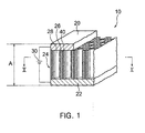
FIG. 1 is a drawing showing the construction of an electrochemical device included in an exhaust gas purification apparatus according to a first embodiment; -
FIG. 2 is a cross-sectional view taken along line II-II of the electrochemical device ofFIG. 1 ; -
FIG. 3 is a drawing showing a construction in which an exhaust gas purification apparatus, including the electrochemical device ofFIG. 1 , is arranged; -
FIG. 4 is a drawing showing an operation of the electrochemical device ofFIG. 1 during purification of exhaust gas; and -
FIG. 5 is a drawing showing the operating principle of an electrochemical device included in a conventional exhaust gas purification apparatus. - The following provides an explanation of embodiments of the present invention based on the appended drawings.
-
FIGS. 1 to 3 are drawings showing the construction of an exhaustgas purification apparatus 120 and the periphery thereof according to a first embodiment. Thepurification apparatus 120 includes anelectrochemical device 10, and theelectrochemical device 10 purifies exhaust gas discharged from an internal combustion engine of a diesel vehicle. Furthermore, this purification is carried out by decomposing nitrogen oxides (NOx) and particulate matter (PM) contained in exhaust gas as will be described later. - As schematically shown in
FIG. 1 , theelectrochemical device 10 is electrically connected to anexternal battery 30. Theelectrochemical device 10 is provided with ananode 20 and acathode 22 as electrodes, theanode 20 is connected to the cathode of thebattery 30, and thecathode 22 is connected to the anode of thebattery 30. - The
electrochemical device 10 is provided with anelectrolyte layer 24 containing electrolytes arranged between theanode 20 and thecathode 22. Theelectrolyte layer 24 allows movement of ions between theanode 20 and thecathode 22. A pathway for this movement of ions serves as a conductive pathway in theelectrolyte layer 24. -
FIG. 2 is a cross-sectional view taken along line II-II of theelectrochemical device 10 ofFIG. 1 . This cross-section is a cross-section of the conductive pathway, namely a cross-section resulting from a plane perpendicular to the direction in which ions are conducted through theelectrolyte layer 24. - The
electrolyte layer 24 contains apolymer film 26 and asupport body 40 having a honeycomb structure and supporting thepolymer film 26. Thepolymer film 26 is an electrolyte exhibiting conductivity with respect to protons H+, and is composed of, for example, Nafion. - The
electrolyte layer 24 is produced, for example, in the manner described below. - First, the
support body 40 having a honeycomb structure is formed. Although thesupport body 40 is composed of cordierite, for example, it may also be composed of SiC. Next, Nafion is coated onto the surface of thesupport body 40, thereby forming thepolymer film 26. Furthermore, this coating is carried out to a degree that allowsvoids 28 to remain within the honeycomb structure. - Although the total thickness of
electrochemical device 10, namely dimension A inFIG. 1 , is 1 mm, for example, this may be suitably altered in consideration of the balance between the strength of theelectrochemical device 10 and the conduction resistance of thepolymer film 26. - Next, the
anode 20 and thecathode 22 are formed using a known technology such as screen printing, on the opposite surfaces of theelectrolyte layer 24, namely both end surfaces of thesupport body 40. In other words, the construction is such that both end surfaces of thesupport body 40 are sandwiched by theanode 20 and thecathode 22. Thus theelectrochemical device 10 is formed. - The
anode 20 is formed by coating with platinum (Pt) followed by firing thereof. Furthermore, the coated material may be another substance, such as rhodium (Rh), provided it has high catalytic activity. - The
cathode 22 is formed by adding barium (Ba) to a nickel (Ni)-based material containing yttria-stabilized zirconia (YSZ) and BaCeO3. Furthermore, another material such as a magnesium (Mg)-based material may be used instead of the Ni-based material. In addition, the Ba added to thecathode 22 may be another substance, provided it has the effect of occluding NOx. - Note that the
anode 20 and thecathode 22 are porous electrodes, and have a structure that allows exhaust gas to pass therethrough. - In addition, the
anode 20 and thecathode 22 may also be composed of a metal mesh or the like. -
FIG. 3 shows a configuration in which theelectrochemical device 10 is arranged in a vehicle exhaust system. - An
exhaust pipe 110 is provided to acombustion engine 100 as a pathway for discharging exhaust gas to the outside, and generated exhaust gas is discharged by passing through this exhaust pipe. Apurification apparatus 120 for purifying exhaust gas is provided within theexhaust pipe 110, and exhaust gas passes through the inside of thepurification apparatus 120. Thepurification apparatus 120 includes a plurality ofelectrochemical devices 10. Note that thebattery 30 ofFIG. 1 is not shown inFIG. 3 . - The plurality of
electrochemical devices 10 are arranged overlapped at fixed intervals in the same orientation at locations that block the flow path of the exhaust gas. This orientation is, for example, such that the electrode surfaces of theelectrochemical devices 10 are vertical to the direction in which the exhaust gas flows. Namely, theanode 20 of a certainelectrochemical device 10 and thecathode 22 of an adjacentelectrochemical device 10 are arranged so as to be parallel. Consequently, exhaust gas flows through the voids 28 (seeFIG. 1 ) of theelectrochemical devices 10. - Next, an explanation is provided of an operation of the
electrochemical device 10 and thepurification apparatus 120 in the present embodiment. - In
FIG. 3 , exhaust gas is generated by the operation of theinternal combustion engine 100, and this exhaust gas reaches thepurification apparatus 120 by passing through theexhaust pipe 110. The exhaust gas first contacts theanode 20 of theelectrochemical device 10 arranged closest to theinternal combustion engine 100. Since theanode 20 is a porous electrode, exhaust gas passes through the inside thereof and enters the void 28 (seeFIG. 1 ) of theelectrolyte layer 24. The exhaust gas then reaches theanode 22 by passing through the void 28 where it contacts thecathode 22. Since thecathode 22 is also a porous electrode, the exhaust gas escapes to the outside of theelectrochemical device 10 by passing through the inside of thecathode 22. - In this manner, the
electrochemical device 10 constitutes a pathway for the passage of exhaust gas, which sequentially passes through theanode 20, the void 28 and thecathode 22, and the exhaust gas passes through this pathway. Subsequently, the exhaust gas reaches theelectrochemical device 10 arranged adjacent thereto, where it passes through thatelectrochemical device 10 in the same manner. - Incidentally, the
electrochemical devices 10 may be arranged in the opposite direction to that described above. That is, the pathway for the passage of exhaust gas may sequentially pass through thecathode 22, the void 28 and theanode 20. - Purification of exhaust gas by the
electrochemical device 10, namely decomposition of PM and NOx, is carried out here. -
FIG. 4 shows an operation of theelectrochemical device 10 during purification of exhaust gas. Transfer of charge is mainly carried out by protons via thepolymer film 26. - Carbon contained in PM in the exhaust gas and H2O in the exhaust gas react on the surface of the
anode 20 and around the periphery thereof, resulting in the formation of CO2, protons and electrons. Electrons are attracted to the cathode of thebattery 30 and migrate to thebattery 30, while protons are attracted to thecathode 22 and migrate within thepolymer film 26. CO2 is discharged to the outside air through theexhaust pipe 110. In this manner, exhaust gas is purified as a result of PM being decomposed around the periphery of theanode 20. - NOx present in exhaust gas and protons conducted by the
polymer film 26 react on the surface of thecathode 22 and around the periphery thereof by accepting electrons supplied from thebattery 30, resulting in the formation of N2 and H2O. The formed N2 and H2O are discharged to the outside air through theexhaust pipe 110. In this manner, exhaust gas is purified as a result of NOx being decomposed around the periphery of thecathode 22. - Here, since the
polymer film 26 contains Nafion as an electrolyte, it operates when the temperature is 80°C or higher. - In this manner, since the exhaust
gas purification apparatus 120 according to the present embodiment is provided with theelectrochemical devices 10 having a conductive pathway composed of thepolymer film 26, it is able to operate at comparatively low temperatures. More specifically, it is able to operate in environments of 80°C or higher. - In particular, the lower limit of the exhaust temperature of diesel engines is low and may be in the vicinity of 100°C or lower, but the
purification apparatus 120 is able to operate even at such a temperature range. Accordingly, thepurification apparatus 120 is able to more effectively purify exhaust gas from diesel engines. - In addition, the electrical conductivity of the Nafion contained in the
polymer film 26 is on the order of 10-1 to 10-2. This is equivalent to that of conventional electrolytes such as solid oxides, for example. - The
polymer film 26 is composed of Nafion in the above-mentioned first embodiment. As a variation thereof, thepolymer film 26 may also have another composition. As an example thereof, since a polymer having hydrophilic sites (such as that composed of sulfonic acid groups) enables the movement of protons through a hydrophilic chain, it can be used as a proton conductive electrolyte. - Incidentally, polymer films generally act as electrolytes in the vicinity of 100°C, and they are therefore able to effectively purify exhaust gas from diesel vehicles.
- Since the performance of polymer films as electrolytes generally decreases rapidly unless hydrated, it is necessary to provide a separate humidifier in fuel cells and the like. In the present embodiment, however, since the
support body 40 has a honeycomb structure and exhaust gas passes through thevoids 28 thereof, thepolymer film 26 coated onto the surface of thesupport body 40 comes into contact with the exhaust gas. Consequently, thepolymer film 26 is spontaneously hydrated by H2O contained in the exhaust gas. Accordingly, it is not necessary to add a hydration member for maintaining the performance of thepolymer film 26. In other words, the configuration of theelectrochemical device 10 can be simplified compared with when it is used in other applications (such as fuel cells). - In the first embodiment described above, the
purification apparatus 120 is used to purify exhaust gas from vehicles. As a variation thereof, the exhaustgas purification apparatus 120 may also be used to purify exhaust gas from a source other than a vehicle. For example, thepurification apparatus 120 may be used in agricultural machinery or power generation plants. Thepurification apparatus 120 may also be used for another exhaust gas provided it contains carbon and NOx. - Although the
support body 40 is composed of a honeycomb structure having hexagonal voids in the first embodiment, the shape of the voids is not limited to being hexagonal, and the voids may also be in the shape of grids, for example. - Therefore, the present examples and embodiments are to be considered as illustrative and not restrictive and the invention is not to be limited to the details given herein but may be modified within the scope of the appended claims.
- This application claims a foreign priority benefit based on Japanese Patent Application No.
2007-300626, filed on November 20, 2007 - A
purification apparatus 120 includes a plurality ofelectrochemical devices 10. Ananode 20 of eachelectrochemical device 10 is connected to a cathode of a battery, and acathode 22 of theelectrochemical device 10 is connected to an anode of the battery. Anelectrolyte layer 24 containing an electrolyte is arranged between theanode 20 and thecathode 22. Theelectrolyte layer 24 contains apolymer film 26 and asupport body 40 having a honeycomb structure and supporting thepolymer film 26. Thepolymer film 26 is an electrolyte that exhibits conductivity with respect to protons H+.
Claims (3)
- An exhaust gas purification apparatus (120) that comprises an electrochemical device (10) and purifies exhaust gas with the electrochemical device (10), characterized in that:the electrochemical device (10) includes an anode (20), a cathode (22) and an electrolyte layer (24) arranged between the anode and the cathode; andthe electrolyte layer (24) comprises a proton conductive polymer electrolyte (26).
- The exhaust gas purification apparatus (120) according to Claim 1, characterized in that:the anode (20) and the cathode (22) are porous electrodes;the electrolyte layer (24) includes a support body (40) having a honeycomb structure;both end surfaces of the support body (40) are sandwiched between the anode (20) and the cathode (22);the proton conductive polymer electrolyte (26) is coated on the support body (40); andthe electrochemical device (10) constitutes a pathway for the passage of exhaust gas, wherein the exhaust gas sequentially passes through one of the electrodes (20,22), voids (28) in the honeycomb structure of the support body (40) and the other of the electrodes (20,22).
- The exhaust gas purification apparatus (120) according to Claim 1, characterized in that the proton conductive polymer electrolyte (26) acts as an electrolyte at 100°C.
Applications Claiming Priority (1)
| Application Number | Priority Date | Filing Date | Title |
|---|---|---|---|
| JP2007300626A JP2009125622A (en) | 2007-11-20 | 2007-11-20 | Exhaust gas purification apparatus |
Publications (1)
| Publication Number | Publication Date |
|---|---|
| EP2062638A1 true EP2062638A1 (en) | 2009-05-27 |
Family
ID=40070629
Family Applications (1)
| Application Number | Title | Priority Date | Filing Date |
|---|---|---|---|
| EP08167643A Withdrawn EP2062638A1 (en) | 2007-11-20 | 2008-10-27 | Exhaust gas purification apparatus |
Country Status (4)
| Country | Link |
|---|---|
| US (1) | US20090162257A1 (en) |
| EP (1) | EP2062638A1 (en) |
| JP (1) | JP2009125622A (en) |
| CN (1) | CN101439257A (en) |
Cited By (3)
| Publication number | Priority date | Publication date | Assignee | Title |
|---|---|---|---|---|
| EP2223732A1 (en) * | 2009-02-06 | 2010-09-01 | Kabushiki Kaisha Toyota Jidoshokki | Exhaust gas purification system |
| EP2363193A3 (en) * | 2010-03-04 | 2012-04-25 | National Tsing Hua University | Electrochemical-catalytic converter for exhaust emission control with power generation |
| EP3581680A1 (en) * | 2018-06-05 | 2019-12-18 | Toyota Jidosha Kabushiki Kaisha | Electrochemical reactor |
Families Citing this family (7)
| Publication number | Priority date | Publication date | Assignee | Title |
|---|---|---|---|---|
| JP2010029796A (en) * | 2008-07-29 | 2010-02-12 | National Institute Of Advanced Industrial & Technology | Carbon removal apparatus and method for removing carbon |
| JP5377247B2 (en) * | 2009-11-27 | 2013-12-25 | 京セラ株式会社 | NOx purification member and NOx purification device |
| TWI491436B (en) * | 2012-12-18 | 2015-07-11 | 國立清華大學 | Production method of exhaust gas purifying reactor |
| JP7183796B2 (en) | 2019-01-08 | 2022-12-06 | トヨタ自動車株式会社 | electrochemical reactor |
| JP7099331B2 (en) | 2019-01-08 | 2022-07-12 | トヨタ自動車株式会社 | Exhaust purification device for internal combustion engine |
| CN113082277B (en) * | 2021-04-26 | 2022-02-08 | 燕山大学 | System and method for treating toxic gas by utilizing power-on coupling plasma |
| NL2030903B1 (en) * | 2022-02-11 | 2023-08-18 | Univ Delft Tech | System and method for converting a nitrogen oxide to a nitrogen product |
Citations (9)
| Publication number | Priority date | Publication date | Assignee | Title |
|---|---|---|---|---|
| DE4446280A1 (en) * | 1994-12-23 | 1996-06-27 | Daimler Benz Ag | Method and a catalyst unit for reducing pollutants, in particular for reducing nitrogen oxides in exhaust gases from internal combustion engines |
| US6036840A (en) * | 1996-05-20 | 2000-03-14 | Dinex A/S | Method and a reactor for electrochemical conversion of a material e.g. soot particles being insoluble in a fluid |
| JP2003265931A (en) | 2002-03-15 | 2003-09-24 | Toyota Motor Corp | Exhaust gas purification reactor |
| US20050230269A1 (en) * | 2002-10-23 | 2005-10-20 | Mitsubishi Denki Kabushiki Kaisha | Nitrogen oxide decomposing element and nitrogen oxide decomposing apparatus including the same |
| US20060183011A1 (en) * | 2004-09-29 | 2006-08-17 | Mittelsteadt Cortney K | Solid polymer electrolyte composite membrane comprising porous ceramic support |
| JP2007130557A (en) * | 2005-11-09 | 2007-05-31 | Mitsubishi Electric Corp | Contaminator |
| GB2437459A (en) * | 2005-01-24 | 2007-10-24 | Nat Inst Of Advanced Ind Scien | Ceramic chemical reaction device capable of decomposing solid carbon |
| JP2007300626A (en) | 2006-05-04 | 2007-11-15 | Hewlett-Packard Development Co Lp | Imaging subsystem using dual shift registers |
| WO2008059888A1 (en) * | 2006-11-14 | 2008-05-22 | The Ritsumeikan Trust | Purifying apparatus, purifying method, exhaust gas purifying system, and method for producing purifying structure |
Family Cites Families (1)
| Publication number | Priority date | Publication date | Assignee | Title |
|---|---|---|---|---|
| US20050282051A1 (en) * | 2003-08-28 | 2005-12-22 | Zhigang Zhou | Integrated honeycomb solid electrolyte fuel cells |
-
2007
- 2007-11-20 JP JP2007300626A patent/JP2009125622A/en active Pending
-
2008
- 2008-10-27 EP EP08167643A patent/EP2062638A1/en not_active Withdrawn
- 2008-11-20 CN CNA2008101776527A patent/CN101439257A/en active Pending
- 2008-11-20 US US12/274,656 patent/US20090162257A1/en not_active Abandoned
Patent Citations (9)
| Publication number | Priority date | Publication date | Assignee | Title |
|---|---|---|---|---|
| DE4446280A1 (en) * | 1994-12-23 | 1996-06-27 | Daimler Benz Ag | Method and a catalyst unit for reducing pollutants, in particular for reducing nitrogen oxides in exhaust gases from internal combustion engines |
| US6036840A (en) * | 1996-05-20 | 2000-03-14 | Dinex A/S | Method and a reactor for electrochemical conversion of a material e.g. soot particles being insoluble in a fluid |
| JP2003265931A (en) | 2002-03-15 | 2003-09-24 | Toyota Motor Corp | Exhaust gas purification reactor |
| US20050230269A1 (en) * | 2002-10-23 | 2005-10-20 | Mitsubishi Denki Kabushiki Kaisha | Nitrogen oxide decomposing element and nitrogen oxide decomposing apparatus including the same |
| US20060183011A1 (en) * | 2004-09-29 | 2006-08-17 | Mittelsteadt Cortney K | Solid polymer electrolyte composite membrane comprising porous ceramic support |
| GB2437459A (en) * | 2005-01-24 | 2007-10-24 | Nat Inst Of Advanced Ind Scien | Ceramic chemical reaction device capable of decomposing solid carbon |
| JP2007130557A (en) * | 2005-11-09 | 2007-05-31 | Mitsubishi Electric Corp | Contaminator |
| JP2007300626A (en) | 2006-05-04 | 2007-11-15 | Hewlett-Packard Development Co Lp | Imaging subsystem using dual shift registers |
| WO2008059888A1 (en) * | 2006-11-14 | 2008-05-22 | The Ritsumeikan Trust | Purifying apparatus, purifying method, exhaust gas purifying system, and method for producing purifying structure |
Cited By (4)
| Publication number | Priority date | Publication date | Assignee | Title |
|---|---|---|---|---|
| EP2223732A1 (en) * | 2009-02-06 | 2010-09-01 | Kabushiki Kaisha Toyota Jidoshokki | Exhaust gas purification system |
| EP2363193A3 (en) * | 2010-03-04 | 2012-04-25 | National Tsing Hua University | Electrochemical-catalytic converter for exhaust emission control with power generation |
| EP3581680A1 (en) * | 2018-06-05 | 2019-12-18 | Toyota Jidosha Kabushiki Kaisha | Electrochemical reactor |
| CN110566319B (en) * | 2018-06-05 | 2021-05-18 | 丰田自动车株式会社 | electrochemical reactor |
Also Published As
| Publication number | Publication date |
|---|---|
| CN101439257A (en) | 2009-05-27 |
| JP2009125622A (en) | 2009-06-11 |
| US20090162257A1 (en) | 2009-06-25 |
Similar Documents
| Publication | Publication Date | Title |
|---|---|---|
| US20090162257A1 (en) | Exhaust gas purification apparatus | |
| US8182658B2 (en) | Electrochemical device and exhaust gas purification apparatus | |
| US4253925A (en) | Method and apparatus for catalytic dissociation of NO | |
| EP2772974B1 (en) | Porous current collector, method for manufacturing same, and fuel cell that uses porous current collector | |
| KR101459406B1 (en) | Catalyst, electrode, fuel cell, gas detoxification apparatus, and methods for producing catalyst and electrode | |
| CN1207210A (en) | High temperature electrochemical transducers for hydrocarbon fuels | |
| US10502106B1 (en) | Electrochemical reactor | |
| KR101824266B1 (en) | Gas decomposition apparatus | |
| US20170077526A1 (en) | Gas decomposition device and power generation device | |
| JP5359552B2 (en) | Gas decomposition apparatus and arrangement structure thereof | |
| CN102958599B (en) | Membrane electrode assembly, fuel cell, gas are poisoned cancellation element and are manufactured the method for membrane electrode assembly | |
| US20090241514A1 (en) | Catalytic converter for the treatment of combustion exhaust gases | |
| JP2013085999A (en) | Gas decomposition device, gas decomposition method, and gas decomposition power generator | |
| EP3030341A1 (en) | Method and system for the purification of exhaust gas with an electrochemical cell | |
| KR102648904B1 (en) | Solid oxide fuel cell for ammonia fuel | |
| JP5487899B2 (en) | Gas cracker | |
| WO2003078031A1 (en) | Chemical reactor for nitrogen oxide removal and method of removing nitrogen oxide | |
| JP2006061837A (en) | Reactor with thermal generator | |
| US20090242423A1 (en) | Oxidizing device with increased oxidizing performance and method of manufacturing the same | |
| JP3780763B2 (en) | Electrochemical catalyst for exhaust gas purification | |
| JP5742075B2 (en) | Gas decomposition element, power generator | |
| JP5304610B2 (en) | Gas cracker | |
| JP5655508B2 (en) | Gas decomposition element, power generation device and gas decomposition method | |
| JP5765664B2 (en) | Gas decomposition apparatus and power generation apparatus | |
| JP2009022928A (en) | Nitrogen oxide decomposition catalyst, nitrogen oxide decomposition apparatus provided with the same, and nitrogen oxide decomposition method using the same |
Legal Events
| Date | Code | Title | Description |
|---|---|---|---|
| PUAI | Public reference made under article 153(3) epc to a published international application that has entered the european phase |
Free format text: ORIGINAL CODE: 0009012 |
|
| 17P | Request for examination filed |
Effective date: 20081027 |
|
| AK | Designated contracting states |
Kind code of ref document: A1 Designated state(s): AT BE BG CH CY CZ DE DK EE ES FI FR GB GR HR HU IE IS IT LI LT LU LV MC MT NL NO PL PT RO SE SI SK TR |
|
| AX | Request for extension of the european patent |
Extension state: AL BA MK RS |
|
| AKX | Designation fees paid |
Designated state(s): DE FR IT |
|
| 17Q | First examination report despatched |
Effective date: 20100601 |
|
| GRAP | Despatch of communication of intention to grant a patent |
Free format text: ORIGINAL CODE: EPIDOSNIGR1 |
|
| STAA | Information on the status of an ep patent application or granted ep patent |
Free format text: STATUS: THE APPLICATION IS DEEMED TO BE WITHDRAWN |
|
| 18D | Application deemed to be withdrawn |
Effective date: 20120306 |