JP5359552B2 - Gas decomposition apparatus and arrangement structure thereof - Google Patents
Gas decomposition apparatus and arrangement structure thereof Download PDFInfo
- Publication number
- JP5359552B2 JP5359552B2 JP2009124625A JP2009124625A JP5359552B2 JP 5359552 B2 JP5359552 B2 JP 5359552B2 JP 2009124625 A JP2009124625 A JP 2009124625A JP 2009124625 A JP2009124625 A JP 2009124625A JP 5359552 B2 JP5359552 B2 JP 5359552B2
- Authority
- JP
- Japan
- Prior art keywords
- gas
- metal
- mea
- gas decomposition
- decomposition
- Prior art date
- Legal status (The legal status is an assumption and is not a legal conclusion. Google has not performed a legal analysis and makes no representation as to the accuracy of the status listed.)
- Active
Links
Images


Landscapes
- Catalysts (AREA)
- Exhaust Gas After Treatment (AREA)
- Exhaust Gas Treatment By Means Of Catalyst (AREA)
Abstract
Description
本発明は、ガス分解装置およびその配置構造であって、より具体的には、電気化学反応を利用して所定のガス成分を効率よく分解することができる、ガス分解装置およびその配置構造に関するものである。 The present invention relates to a gas decomposition apparatus and an arrangement structure thereof, and more specifically to a gas decomposition apparatus and an arrangement structure thereof that can efficiently decompose a predetermined gas component using an electrochemical reaction. It is.
自動車では、ディーゼルエンジン搭載の自動車が増加する傾向にあるが、廃ガス規制をクリアする必要があり、ディーゼルエンジンの排出ガス中の所定成分を低減する各種の触媒装置が開発されている。それらの触媒装置のなかで、尿素選択還元システムは、NOxをエンジンスピードが低い温度域で効率よく窒素および水へと還元浄化するものとして推奨されている(非特許文献1)。これらの排気ガス浄化装置は、自動車エンジンの排気経路に取り付けられ、排気ガスを浄化する。このために、排気経路の温度やNOx濃度を測定して、尿素の排気経路への噴射量の制御を行う。たとえば、尿素噴射の後段にNOxセンサを設け、NOとNO2とを化学量論的に個別に割り出し、最適な尿素の噴射量を制御する装置が提案されている(特許文献1)。また、排気経路に酸化触媒を、その後段に尿素選択還元装置を配置して、尿素選択還元装置の前段において酸化触媒の前後に配置した2つのNOxセンサを用いて、NOx分解を行う方法の提案もある(特許文献2)。
また、金属ハニカムの表面に、NOx還元触媒と、炭化水素の酸化触媒と、イオン導電性の固体電解質と、を分散配置して、電気化学的にNOxを分解する方法の提案がなされている(特許文献3)。この発明では、金属ハニカムとして、波状加工されたステンレス鋼と、ステンレス鋼平板との重ね合わせにより得られるハニカム構造(特許文献4)が挙げられている。
また、電気化学反応によってNOx分解を促進するために、固体電解質層を挟むアノードとカソードの電圧を印加する方法が提案されている(特許文献5)。さらにNOx分解容量を拡大して実用化するために、板状の「アノード/固体電解質/カソード」を主構成要素とするMEAを、十数枚、蛇腹状(畝状)に加工された金属板をインターコネクタとして介在させて積層することでモジュール化する構造の提案がなされている(非特許文献2)。
As for automobiles, automobiles equipped with diesel engines tend to increase. However, it is necessary to satisfy waste gas regulations, and various catalyst devices for reducing predetermined components in exhaust gas of diesel engines have been developed. Among these catalytic devices, the urea selective reduction system is recommended as one that efficiently reduces and purifies NOx into nitrogen and water in a temperature range where the engine speed is low (Non-patent Document 1). These exhaust gas purification devices are attached to the exhaust path of an automobile engine and purify the exhaust gas. For this purpose, the temperature of the exhaust passage and the NOx concentration are measured to control the injection amount of urea into the exhaust passage. For example, a device has been proposed in which a NOx sensor is provided at the subsequent stage of urea injection, and NO and NO 2 are separately determined stoichiometrically to control the optimum urea injection amount (Patent Document 1). Also, a proposal of a method of performing NOx decomposition using an oxidation catalyst in the exhaust path, a urea selective reduction device in the subsequent stage, and two NOx sensors arranged before and after the oxidation catalyst in the previous stage of the urea selective reduction device There is also (patent document 2).
Further, there has been proposed a method of electrochemically decomposing NOx by dispersing and arranging a NOx reduction catalyst, a hydrocarbon oxidation catalyst, and an ion conductive solid electrolyte on the surface of a metal honeycomb ( Patent Document 3). In the present invention, a honeycomb structure obtained by superimposing corrugated stainless steel and a stainless steel plate is cited as a metal honeycomb (Patent Document 4).
Moreover, in order to promote NOx decomposition by an electrochemical reaction, a method of applying a voltage between an anode and a cathode sandwiching a solid electrolyte layer has been proposed (Patent Document 5). Furthermore, in order to expand the NOx decomposition capacity and put it to practical use, a metal plate in which dozens of MEAs mainly composed of a plate-like “anode / solid electrolyte / cathode” are processed into a bellows shape (saddle shape) There has been proposed a structure that forms a module by interposing layers as interconnectors (Non-Patent Document 2).
NOxを分解する尿素選択還元装置については、自動車にとって大掛かりな尿素選択還元装置を排気系統に配置するものであり、重量増をもたらす。自動車用では、当然のことながら小型で軽量であることが強く要求される。
また、金属ハニカムの表面に、NOx還元触媒等を分散配置した方法では、金属ハニカムは薄くて、圧力損失がある程度低くなる利点はあるものの、電気化学反応箇所の密度はそれほど向上せず、また圧力損失の低減も十分ではない。すなわち、小型化と分解効率との両方を推進する点で、不十分である。
電気化学反応を用いる方法では、装置が大掛かりにならない利点を有する。しかし、これまでの容量拡大をはかるモジュール化方式においては、インターコネクタに適切な形態の材料がなく、改善の余地がある。インターコネクタは、当該インターコネクタに接触する電極(アノードまたはカソード)に対し集電作用を奏するとともに、通気性よく気体を通しながら、電極と当該気体との接触を良くする作用を持たなければならない。しかしながら、蛇腹状のインターコネクタを用いた従来の電気化学反応装置では、分解対象のガス成分が電極と接触せずに素通りする割合が高い配置と、それを避けられるが圧力損失が増大する配置とがあり、実際はその中間の配置をとることになる。しかし、この中間的な配置の場合でも、蛇腹の凹凸およびピッチが大きいため、分解対象ガスは電極と接触せずに素通りをする割合が高い。このため、圧力損失、および、気体と電極との接触、の両方をともに向上できるガス分解装置の開発が求められている。
Regarding the urea selective reduction device that decomposes NOx, a urea selective reduction device that is large for an automobile is arranged in the exhaust system, resulting in an increase in weight. For automobiles, as a matter of course, it is strongly required to be small and light.
In addition, the method in which the NOx reduction catalyst or the like is dispersedly arranged on the surface of the metal honeycomb has the advantage that the metal honeycomb is thin and the pressure loss is reduced to some extent, but the density of the electrochemical reaction site is not so improved, and the pressure is reduced. Loss reduction is not sufficient. That is, it is insufficient in terms of promoting both miniaturization and decomposition efficiency.
The method using an electrochemical reaction has an advantage that the apparatus does not become large. However, in the conventional modularization method for expanding the capacity, there is no room for an appropriate form for the interconnector, and there is room for improvement. The interconnector must have a function of collecting current with respect to the electrode (anode or cathode) in contact with the interconnector and improving the contact between the electrode and the gas while allowing gas to pass therethrough. However, in the conventional electrochemical reaction apparatus using the bellows-like interconnector, the arrangement in which the gas component to be decomposed passes through without contacting the electrode is high, and the arrangement in which the pressure loss increases while avoiding it. There is actually an intermediate arrangement. However, even in this intermediate arrangement, since the irregularities and pitch of the bellows are large, the decomposition target gas passes through without contacting the electrode. For this reason, development of the gas decomposition apparatus which can improve both a pressure loss and the contact of gas and an electrode is calculated | required.
本発明は、電気化学反応を用いて所定のガスを分解する積層タイプの装置において、積層したMEAの間を、通気性よく気体を通しながら、電極と当該気体との接触を良くすることができる、ガス分解装置、およびその配置構造を提供することを目的とする。 INDUSTRIAL APPLICABILITY The present invention can improve the contact between an electrode and the gas in a stacked type apparatus that decomposes a predetermined gas using an electrochemical reaction while passing gas between the stacked MEAs with good air permeability. An object of the present invention is to provide a gas decomposition apparatus and an arrangement structure thereof.
本発明のガス分解装置は、積層構造を構成する2層以上のMEA(Membrane Electrode Assembly)を備え、MEAの間に介在して導電するためのインターコネクタに、金属多孔体を用い、金属多孔体に金属めっき体を用いたことを特徴とする。 The gas decomposition apparatus of the present invention includes two or more layers of MEA (Membrane Electrode Assembly) constituting a laminated structure, and uses a metal porous body as an interconnector to be interposed between the MEAs to conduct electricity. It is characterized by using a metal plating body .
上記の構成により、分解対象のガス成分を含む気体は、少なくとも金属多孔体のインターコネクタの部分を電気化学反応しながら通り過ぎる。上記の気体は、分解対象のガス成分(被処理ガス)を含み、さらに他のガス成分を含んでもよい(後述する混合気体)。ガス分解装置は、インターコネクタの部分が、気体の主要流路を構成するように排ガス流路内に設置される。たとえば、少なくともインターコネクタの部分に対して抜け道となる流路が他にないようにするのがよい(端部接続層についての問題はあとで詳説する。)。金属多孔体は、当該金属多孔体を構成する材料について大きい気孔率を選択することで圧力損失を減少させながら、気体の乱流化を促進することができる。乱流状態の気体は、層流のようにMEAの表面に停滞する表面層を作らず、MEA表面に接触する気体層を絶えず剥がして新しい気体をMEAの表面に供給する。このため、圧力損失を低下させる気孔率を選択しながら、気体の乱流化という要因を通じて電気化学反応を促進させることができる。
また、金属多孔体は、孔以外の骨格部等は金属で形成されるので、高い導電率を有し、インターコネクタ、端部接続部材(集電材)としての電気的特性を備えている。金属多孔体は、シート状または層状のものを用いるが、単層でも、または単層を重ねた複層であってもよい。また、分解対象のガス成分の他に、別の種類のガスを含む気体を混合気体と呼ぶ。混合気体は、複数種類の別のガス成分を含んでもよい。
上記の金属多孔体を、金属めっき体とする。ここで、金属めっき体は、樹脂に気泡を形成して、連続化処理の後、金属めっきするものである。金属多孔体の孔は、樹脂中の気泡サイズや金属めっき厚み等に影響を受ける。気泡サイズは、広い範囲に制御することができる。また孔を形成する金属骨格は金属めっきで形成され、所定範囲内の任意の厚みに形成することができる。これによって、乱流の反応促進作用を確保しながら、金属粒子の焼結体や金属繊維に比較して、気孔率を高くでき、通気性が良く、圧力損失の小さいカソード集電体とすることができる。なお、上記の金属多孔体は、柱状の金属めっき体が連続する骨格をなしている場合が多い。
With the above configuration, the gas containing the gas component to be decomposed passes through at least the interconnector portion of the porous metal body while performing an electrochemical reaction. Said gas contains the gas component (to-be-processed gas) of decomposition | disassembly object, and may also contain another gas component (mixed gas mentioned later). The gas decomposition apparatus is installed in the exhaust gas flow path so that the interconnector portion constitutes the main gas flow path. For example, it is preferable that there is no other flow path serving as a passage for at least the portion of the interconnector (the problem regarding the end connection layer will be described in detail later). The porous metal body can promote gas turbulence while reducing pressure loss by selecting a large porosity for the material constituting the porous metal body. The turbulent gas does not form a surface layer stagnating on the surface of the MEA like a laminar flow, and constantly peels off the gas layer in contact with the MEA surface and supplies new gas to the surface of the MEA. For this reason, an electrochemical reaction can be promoted through a factor of gas turbulence while selecting a porosity that reduces pressure loss.
Moreover, since the skeleton part other than the hole is made of metal, the metal porous body has high electrical conductivity and has electrical characteristics as an interconnector and an end connection member (current collector). The metal porous body is in the form of a sheet or a layer, but it may be a single layer or a multilayer in which single layers are stacked. In addition to the gas component to be decomposed, a gas containing another type of gas is called a mixed gas. The mixed gas may contain a plurality of different gas components.
Let said metal porous body be a metal plating body. Here, a metal plating body forms a bubble in resin, and metal-plates after a continuous process. The pores of the metal porous body are affected by the bubble size in the resin, the metal plating thickness, and the like. The bubble size can be controlled in a wide range. The metal skeleton that forms the holes is formed by metal plating and can be formed to have an arbitrary thickness within a predetermined range. As a result, the cathode current collector can be made to have a higher porosity, better air permeability, and lower pressure loss than the sintered body of metal particles and metal fibers while ensuring a turbulent reaction promoting action. Can do. The porous metal body often has a skeleton in which columnar metal plating bodies are continuous.
さらに積層構造の端層を構成するMEAの外側の電極に接する端部接続層(集電材)に、金属めっき体を用いることができる。これによって、積層構造を構成するすべてのMEAは、両面から金属めっき体特有の高密度の微細な多点接触によって挟まれる。このため、焼結体である、固体電解質、アノードおよびカソードの脆さに起因して、多層構造にするのが容易ではないMEAに対して、均等に調節された圧力をかけて保持することが容易となる。金属めっき体は、MEAに対して、面全体に均等に、単位面積当たりの応力は小さく調節しながら微細な多点応力をかけて、多層構造に保持することが容易となる。すなわち金属多孔体にクッションの役割を担わせることができる。
なお、インターコネクタにのみ金属多孔体を用いて、端部接続層に金属多孔体を用いない場合でも、端層を構成するMEA以外のMEAについては、両側から面全体に均等に、単位面積当たりの応力は小さく調節しながら微細な多点応力をかけて、多層構造に保持することが容易となる。
Furthermore, a metal plating body can be used for the end connection layer (current collector) in contact with the outer electrode of the MEA constituting the end layer of the laminated structure. Thereby, all the MEAs constituting the laminated structure are sandwiched from both sides by high-density fine multipoint contact specific to the metal plating body . For this reason, it is possible to hold the MEA, which is not easy to have a multilayer structure due to the brittleness of the solid electrolyte, anode and cathode, which are sintered bodies, by applying an evenly regulated pressure. It becomes easy. The metal plated body can be easily held in a multilayer structure by applying fine multipoint stress to the MEA evenly over the entire surface while adjusting the stress per unit area to be small. That is, the metal porous body can have a role of a cushion.
In addition, even when a metal porous body is used only for the interconnector and a metal porous body is not used for the end connection layer, the MEA other than the MEA constituting the end layer is equal to the entire surface from both sides per unit area. It is easy to apply a fine multi-point stress while adjusting the stress to a multi-layered structure while keeping the stress small.
MEAの単層の厚みを0.25mm〜1.5mmとして、金属めっき体の厚みを0.5mm〜5mmとすることができる。これによって、厚み方向の電場を均質にMEAの電解質内に形成し、かつ気体流路の断面積を広く形成しながら、MEAに対するクッションの役割を担わせることができる。金属めっき体の厚みが0.5mm未満では、単層では気体流路が狭くなり、またクッション性を十分発揮することが難しい。この場合は、手数をかけて積層した金属めっき体を用いる必要があり、工数の増大を招き、また積層した金属めっき体どうしのずれ等について対策をとる必要がある。一方、厚みが5mmを超えると、乱流化を促進するものの、気体の流路長さが短いとすべてのガス成分がMEAに十分接触してガス成分を分解させることが難しくなる。たとえばカソードで分解反応するガス成分が、インターコネクタのアノード側に進入してきた場合、当該インターコネクタを通り抜ける間に、すべての当該ガス成分が、反対側のカソードに接触することが難しくなる。インターコネクタの長さを大きくとれる構成の場合には、この厚みの上限は緩和される。 The thickness of the single layer of MEA can be 0.25 mm to 1.5 mm, and the thickness of the metal plating body can be 0.5 mm to 5 mm. Thus, the electric field in the thickness direction can be formed uniformly in the electrolyte of the MEA, and the gas channel can have a wide cross-sectional area, and the role of a cushion for the MEA can be played. When the thickness of the metal plating body is less than 0.5 mm, the gas flow path becomes narrow in a single layer and it is difficult to sufficiently exhibit cushioning properties. In this case, it is necessary to use a metal plating body that is laminated in a laborious manner , increasing man-hours, and taking measures against misalignment between the laminated metal plating bodies . On the other hand, if the thickness exceeds 5 mm, turbulence is promoted, but if the gas flow path length is short, it is difficult for all gas components to sufficiently contact the MEA and decompose the gas components. For example, when a gas component that undergoes decomposition reaction at the cathode enters the anode side of the interconnector, it is difficult for all the gas components to contact the cathode on the opposite side while passing through the interconnector. In the case where the length of the interconnector can be increased, the upper limit of the thickness is relaxed.
金属めっき体の気孔率を、0.6以上0.98以下とすることができる。これによって、非常に良好な通気性を得ることができる。気孔率が0.6未満では、圧力損失が大きくなり、ポンプ等による強制循環をするとエネルギー効率が低下し、またイオン導電材等に曲げ変形等を生じて好ましくない。圧力損失を低減し、イオン導電材の損傷を防止するために、気孔率は、0.8以上とするのがよく、更に好ましい範囲として0.9以上とする。一方、気孔率が0.98を超えると電気伝導性が低下して集電機能が低下する。 The porosity of the metal plating body can be 0.6 or more and 0.98 or less. Thereby, very good air permeability can be obtained. If the porosity is less than 0.6, the pressure loss becomes large, and if forced circulation by a pump or the like is performed, the energy efficiency is lowered, and bending deformation or the like occurs in the ion conductive material or the like. In order to reduce the pressure loss and prevent the ion conductive material from being damaged, the porosity is preferably 0.8 or more, and more preferably 0.9 or more. On the other hand, when the porosity exceeds 0.98, the electrical conductivity is lowered and the current collecting function is lowered.
上記のガス分解装置は、内燃機関を有する自動車に搭載され、当該内燃機関の廃熱により当該ガス分解装置を加熱するための加熱機構を備えることができる。これによって、高いエネルギー効率でNOx分解を高速で行うことが可能になる。 The gas decomposition apparatus is mounted on an automobile having an internal combustion engine, and can include a heating mechanism for heating the gas decomposition apparatus with waste heat of the internal combustion engine. This makes it possible to perform NOx decomposition at high speed with high energy efficiency.
本発明のガス分解装置の配置構造は、積層構造を構成する2層以上のMEAを備えて分解対象のガス成分を電気化学反応により分解するためのガス分解装置を、ガス成分を含む気体が流れる流路に、配置する構造である。この配置構造では、MEAの間に介在して導電するためのインターコネクタ、および積層構造の両端に位置するMEAの外側の電極表面に接する端部接続層、を、金属多孔体とし、該金属多孔体に金属めっき体を用い、流路の壁と、ガス分解装置との間に隙間がないように気密保持部材が配置されることを特徴とする。 The gas decomposition apparatus according to the present invention has an arrangement structure in which a gas containing a gas component flows through a gas decomposition apparatus that includes two or more MEAs constituting a laminated structure and decomposes a gas component to be decomposed by an electrochemical reaction. The structure is arranged in the flow path. This arrangement, interconnector for conducting interposed between the MEA, and the end portion connecting layer in contact with the outer electrode surface of the MEA located at both ends of the laminate structure, and a porous metal body, the metal porous A metal plating body is used for the body, and an airtight holding member is arranged so that there is no gap between the wall of the flow path and the gas decomposition apparatus.
上記の構成によって、MEAの電極に接触する可能性がない部分を通って、上記混合気体が素通りすることが防止される。混合気体中の分解対象のガス成分は、通常、極低濃度まで分解されることが要求される。ガス成分の素通りを防止することで、極低濃度まで分解する条件が確保される。 With the above-described configuration, the mixed gas is prevented from passing through a portion where there is no possibility of coming into contact with the electrode of the MEA. The gas component to be decomposed in the mixed gas is usually required to be decomposed to an extremely low concentration. By preventing the passage of gas components, conditions for decomposition to extremely low concentrations are ensured.
内燃機関を有する自動車のマフラーを上記の流路とすることができる。これによって、廃熱を利用しながら、排気ガスをクリーン化する際のエネルギー効率を向上することができる。 A muffler of an automobile having an internal combustion engine can be used as the flow path. This can improve energy efficiency when exhaust gas is cleaned while using waste heat.
ガス分解装置が複数あり、流路に沿って直列に、複数、配置することができる。これによって、ガス成分の濃度を極低濃度にすることが容易となる。 There are a plurality of gas decomposition apparatuses, and a plurality of gas decomposition apparatuses can be arranged in series along the flow path. Thereby, it becomes easy to make the concentration of the gas component extremely low.
両端に位置するMEAの外側の電極のうち一方は、ガス成分の分解が生じないほうの電極であり、当該ガス成分の分解が生じない電極に接する端部接続層の金属めっき体には、ガス成分を流さないようにするのがよい。これによって、2つあるうちの一方の端部接続層を、ガス成分が素通りするのを防止することができる。たとえばガス成分がアノードでは分解反応しない場合、アノードに接する端部接続層を通る混合気体のなかのガス成分は、この端部接続層を素通りする。端部接続層を通る混合気体の割合は、MEAの多層構造の層数を増大させれば小さくなる。しかし、ガス成分を、たとえば一段で極低濃度たとえば数ppmまで分解することが要求される場合には、一方の端部接続層にガス成分を流さないようにするのがよい。 One of the electrodes outside the MEA located at both ends is an electrode that does not cause decomposition of the gas component, and the metal plating body of the end connection layer that is in contact with the electrode that does not cause decomposition of the gas component includes a gas It is better not to let the components flow. Thereby, it is possible to prevent the gas component from passing through one of the two end connection layers. For example, when the gas component does not decompose at the anode, the gas component in the mixed gas passing through the end connection layer in contact with the anode passes through the end connection layer. The ratio of the mixed gas passing through the end connection layer decreases as the number of layers of the MEA multilayer structure is increased. However, when it is required to decompose the gas component to, for example, a very low concentration, for example, several ppm in one stage, it is preferable that the gas component does not flow through one end connection layer.
本発明によれば、電気化学反応を用いて所定のガスを分解する積層タイプの装置において、積層したMEAの間を、通気性よく気体を通しながら、電極と当該気体との接触を良くすることができる、ガス分解装置、およびその配置構造を得ることができる。 According to the present invention, in a stacked type apparatus that decomposes a predetermined gas using an electrochemical reaction, the gas is passed between the stacked MEAs with good air permeability, and the contact between the electrode and the gas is improved. The gas decomposition apparatus and its arrangement structure can be obtained.
(実施の形態1)
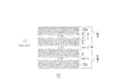
図1は、本発明の実施の形態1におけるガス分解装置10を示す断面図である。図1において、3つのMEAは同じものであり、固体電解質1を挟んで一方にアノード2が、また他方にカソード3が配置される。3つのMEAの間に介在するインターコネクタ5には金属めっき体で形成された金属多孔体が用いられている。また、両端に位置するMEAの外側の電極に接する端部接続層(電源とMEAとを電気的に接続する集電材)15a,15cにも、同じ金属多孔体が用いられている。金属めっき体による、低圧力損失および高導電性の顕著な作用については、このあと金属多孔体の項で詳しく説明する。
端部接続層15aは、一方の端のMEAの外側電極であるアノード2と電源の高電位側とを、また、端部接続層15cは、他方の端のMEAの外側電極であるカソード3と電源の低電位側とを、電気的に接続する。このような形態のガス分解装置10は、NOx分解装置に限られないが、以下の説明では、NOx分解装置として説明する。すなわち、ガス分解装置10は、NOxを含む気体が排気される排気路内に配置され、NOxはカソード3において分解される。混合気体中に、(カソード3でNOxの分解/アノード2で「所定のガス成分」の分解)、という、NOxと対をなす所定のガス成分が、含まれることは想定していないが、含まれていてもよい。ただ、このような所定のガス成分を、排気路(たとえばマフラー)に意図して導入することはコスト増などを招くので、意図して含ませることはしない。アノード2では、カソード3で生成され固体電解質1を経由して移動してきた酸素イオン等が反応して、酸素分子(酸素ガス)が発生する。ガス分解装置10で用いられる電力がこの化学反応を駆動する。この分解反応が、実用レベルの反応速度となるように、ガス分解装置は、250℃〜650℃の温度に加熱されて稼働するものとする。
図1において、NOxを含む気体(混合気体)が、MEAの積層構造に導入され、インターコネクタ5および端部接続層15a,15cを構成する金属多孔体を通り抜ける。他の部分、たとえばガス分解装置10の周囲を通り抜けることは、NOxが素通りすることを意味するので、NOx濃度を非常に低い範囲、たとえばppmオーダーまで低下させる場合には、好ましくない。このため、上記の混合気体は、インターコネクタ5および端部接続層15a,15cを構成する金属多孔体、以外の部分を通り抜けできないように、配置する必要がある(図6参照)。
(Embodiment 1)
FIG. 1 is a cross-sectional view showing a
The
In FIG. 1, a gas (mixed gas) containing NOx is introduced into the laminated structure of MEA and passes through the metal porous body constituting the
従来は、インターコネクタには、蛇腹状または畝状に加工されたステンレススティール板が用いられていた。この場合、蛇腹状の金属板がMEAに接触する部分は、畝状の平坦頂部であり、蛇腹の凹凸も、またその凹凸のピッチも大きい。MEAは、固体電解質1、アノード2およびカソード3が、薄く、かつ焼結体であるため、脆いことで知られている。蛇腹状の金属板を介在させてMEAを積層した場合、押さえる領域がずれることで、曲げ応力等がMEAに生じて、簡単に破損にいたる。加熱中に温度差に起因する熱応力も加わるので、破損はさらに生じやすい。上記のように、金属めっき体の表面に均等に無数に分散している微小接続部で、両側からMEAを挟んで保持することで、金属めっき体が一種のクッション材のように作用する。このため、MEAに曲げ応力や局所的に高い応力を付加することがない。この結果、金属多孔体は、外力等に対する緩衝材として働き、脆いMEAを安定して確実に保持することができる。
Conventionally, a stainless steel plate processed into a bellows shape or a saddle shape has been used for an interconnector. In this case, the portion where the bellows-shaped metal plate contacts the MEA is a bowl-shaped flat top, and the irregularities of the bellows and the pitch of the irregularities are large. MEA is known to be brittle because the
電気化学反応が、たとえば外部電源から電圧を印加して電気分解反応である場合、導電率が低い電極材料の場合、従来の蛇腹状のインターコネクタでは、固体電解質1に、電源電圧に見合った電場を、均等に形成することができないことが考えられる。ただし、導電率が高い電極の場合は、集電材がまばらに電極に接触しても全体が等電位になり、下記の問題は生じない。
一方側の電極の導電率が低いと、蛇腹状のインターコネクタのように接触する間隔が粗い場合、電源電圧に見合った電場を固体電解質全体に均一に形成することができず、ムラを生じると考えられる。
本実施の形態では、インターコネクタ5、および、端部接続層15a,15cを構成する金属めっき体は、MEAに、表面に均等に無数に分散している微小接続部または接触点で電気的に接続する。このため、MEAの全面にわたって上下両側から電気的に接続するので、固体電解質1の全体にわたって均等に厚み方向の電場を形成することができる。すなわち電源電圧に見合った電場が、ムラ無く固体電解質1全体にわたって形成される。このため、カソード3で生成する酸素イオンO2−は固体電解質1の全面にわたって、最短時間で、アノード2に到達することができる。上記の金属多孔体をインターコネクタ5および端部接続層15a,15cに用いることで、酸素イオンの固体電解質1の移動時間短縮を得ることができる。
For example, when the electrochemical reaction is an electrolysis reaction by applying a voltage from an external power source, or in the case of an electrode material with low electrical conductivity, the conventional bellows-like interconnector has an electric field corresponding to the power source voltage in the
If the conductivity of the electrode on one side is low, the contact field is rough like the bellows-like interconnector, and the electric field corresponding to the power supply voltage cannot be formed uniformly throughout the solid electrolyte, resulting in unevenness. Conceivable.
In the present embodiment, the
図2は、本実施の形態におけるNOx分解装置10のカソード3における電気化学反応を示す図である。また図3は、アノード2における電気化学反応を示す図である。アノード2およびカソード3は、既知のどのような材料で構成されてもよいが、ガス成分の出入りが容易なように、通常、焼結によって形成された多孔体であり、たとえばカソード3内には孔が存在する。アノード2にも、無数に孔はある。本実施の形態例では、たとえば、カソード3は、酸素イオン導電性電解質32と、Ni粒連鎖体31aとその酸化層31bとで形成される酸化層付きNi粒連鎖体31とで形成するのがよい。また、アノード2は、酸素イオン導電性セラミックス22と、触媒の銀粒子23とで形成するのがよい。カソード3およびアノード2の材料の具体例は、あとで詳しく説明する。
FIG. 2 is a diagram showing an electrochemical reaction at the
インターコネクタ5の金属めっき体に導入された、混合気体のうち、焼結体であるカソード3に接触または進入する混合気体中のNOxは、図2に示すように、次の反応をして、酸素イオンを、イオン導電性セラミックス32を経由させて固体電解質へと送り出す。カソード反応:2NO2+8e−→N2+4O2−、または2NO+4e−→N2+O2−、が生じる。カソード反応で生じた酸素イオンO2−は、電場が形成されている固体電解質1を通ってアノード2に向かう。
図2において、金属めっき体で形成されるインターコネクタ5は、骨格部(めっき部)5aと、その間の孔部5hとで形成されている。
一方、図3に示すように、アノード2では、固体電解質1を移動してきた酸素イオンO2−同士が、次の反応をする。アノード反応:O2−+O2−→O2+4e−の反応が生じる。電子e−は、アノード2から外部回路を経て、カソード3に至り、上記のカソード反応にあずかる。
Of the mixed gas introduced into the metal plating body of the
In FIG. 2, the
On the other hand, as shown in FIG. 3, in the
排気である混合気体の中に配置されて、カソード3においてNOxを分解し、アノードで酸素ガスを生成する電気化学反応は、電力を投入しないと進行しない電気分解反応である。このために、電源を必要とする。図1に示す電源は、アノード2とカソード3との間に10V〜20Vを印加できればよいが、それより高い電圧、たとえば50V程度の公称電圧のものであってもよい。この電圧印加によって、アノード反応およびカソード反応を含む全体の電気化学反応が促進され、また固体電解質1に形成される電場によって酸素イオンの固体電解質1の移動時間の短縮をはかることができる。固体電解質1内の酸素イオンの移動時間によって、分解反応が律速される場合が多いので、上記の電場による酸素イオンの加速は分解反応速度を向上させる上で効果的である。
The electrochemical reaction that is arranged in the mixed gas that is exhaust gas, decomposes NOx at the
−金属多孔体−
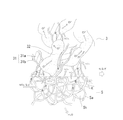
インターコネクタ5および端部接続層15a,15cに用いる金属多孔体は、めっきで形成された金属めっき体とする。この金属めっき体には、導電性および通気性が求められ、とくに通気性については圧力損失を生じにくいことが求められる。このような圧力損失を抑制できる高い通気性を持つ金属めっき体は、金属粒子や金属繊維の焼結体では得にくい。上記の特性を備える金属多孔体として、たとえば三角柱状の骨格が3次元に連なって連続気孔を形成する金属めっきの金属多孔体があり、その典型材として、たとえば住友電気工業(株)製のセルメット(商標登録)を用いることができる。図4は、めっき多孔体の製造方法の一例を示す図である。図4において、まずウレタン等の樹脂に発泡処理を施し発泡させたものを準備する。次いで、発泡した気孔を連続する気孔連続化処理を行う。気孔連続化処理は、除膜処理と呼ばれる処理であるが、ポリウレタン発泡体のセル膜(気泡膜)を除去する公知の処理である。公知の除膜処理として、アルカリ濃厚溶液中にポリウレタン発泡体を浸漬して加水分解によりセル膜を溶解除去するアルカリ処理法や、浸透剤によってポリウレタン発泡体中に水を含浸させ、その水を100℃以上に加熱して水の体積膨張でセル膜を破壊する湿潤過熱法や、ポリウレタン発泡体を密封容器に収容し、前記密封容器に水素、酸素の混合等からなるガスを充填して爆破させることによりセル膜を破壊させる熱処理(爆発法)などがある。上記の除膜処理によって、ポリウレタン発泡体はセル膜のほとんどが除去され、ほぼ骨格のみとなる。このあと、気孔内壁に、導電性炭素膜を付着させるか、または無電解めっき等により導電薄膜を形成する。次いで、電気めっきによって、金属めっき層を導電性炭素膜または導電薄膜上に形成する。この金属めっき層が気孔体の骨格となる。金属めっきはニッケルイオンを含むめっき液を用い、Niめっき層を形成するのがよい。Niは、上記の低温域で耐高温酸化性を有し、かつめっき層の形成が容易である。次いで、熱処理によって樹脂を消散させて、金属めっき層のみを残して、Niめっき多孔体とする。
より高温での耐酸化性能を得るためには、Niめっき多孔体に対して合金化処理を施すことができる。この合金化処理は、Cr、Al、その他の金属を外から表層に拡散導入することにより行われる。合金化を表層のみに止めて、合金化表層付きめっき多孔体とするのが普通であるが、中まで合金化する場合もある。
また、図4には示していないが、めっき液にニッケルイオンおよび他の金属イオンを溶解させて、めっき体をニッケル合金とすることができる。そのように、直接、合金めっき層を形成することで、ニッケル合金の骨格を形成してもよい。
-Porous metal-
Metal porous body used for the
In order to obtain oxidation resistance at higher temperatures, the Ni-plated porous body can be alloyed. This alloying treatment is performed by introducing Cr, Al, and other metals from the outside into the surface layer. Usually, alloying is stopped only on the surface layer to form a plated porous body with an alloyed surface layer.
Although not shown in FIG. 4, nickel ions and other metal ions can be dissolved in the plating solution to make the plated body a nickel alloy. As such, a nickel alloy skeleton may be formed by directly forming an alloy plating layer.
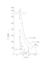
図4に示す方法で製造したNiめっき多孔体の、比表面積(y:m2/m3)と孔径(x:mm)との関係を図5に示す。図5の小黒丸が実測値である。孔径0.45mm〜3.2mmにわたって、上記の方法で製造することができる。実測値は、(x−0.3)y=400または600の双曲線に比して、同じ孔径において大きな比表面積を持つ。金属多孔体について、(1)孔径はSEM(Scanning Electric Microscopy:走査型電子顕微鏡)観察により、(2)比表面積はBET表面積法により、(3)気孔率は表面積、体積および重量から、それぞれ求めるのがよい。(x−0.3)yの値が大きいと、カソード集電体12に導入される気体と接触して、カソード3へと気体を乱流状態で送り込む機能を保持しながら、圧力損失を低くできる効果を生み出す。このため、400≦(x−0.3)y、とするのがよい。より好ましくは、600≦(x−0.3)y、とするのがよい。孔径をあまり大きくする弊害(導電性の低下など)が生じるおそれがあるので、上限は3000程度、より好ましくは2000程度とするのがよい。
Niめっき多孔体では、気孔の大きさ、および、骨格の太さ(薄さ)を、それぞれ独立に調節することができる。このため、Niめっき多孔体は、十分な導電性、十分な乱流生成作用を得ながら、容易に圧力損失を低下させることができる。
FIG. 5 shows the relationship between the specific surface area (y: m 2 / m 3 ) and the pore diameter (x: mm) of the Ni-plated porous body produced by the method shown in FIG. The small black circles in FIG. 5 are actually measured values. It can manufacture with said method over hole diameter 0.45mm-3.2mm. The measured value has a large specific surface area at the same pore diameter as compared with the hyperbola of (x−0.3) y = 400 or 600. For metal porous bodies, (1) pore diameter is determined by SEM (Scanning Electric Microscopy) observation, (2) specific surface area is determined by BET surface area method, and (3) porosity is determined from surface area, volume and weight. It is good. When the value of (x−0.3) y is large, the pressure loss is reduced while maintaining the function of contacting the gas introduced into the cathode current collector 12 and sending the gas into the
In the Ni-plated porous body, the size of the pores and the thickness (thinness) of the skeleton can be adjusted independently. For this reason, the Ni-plated porous body can easily reduce the pressure loss while obtaining sufficient conductivity and sufficient turbulent flow generation action.
カソード3、アノード2、および固体電解質1を形成する材料については、上述のようにとくに限定する必要はない。これから説明するカソード3、アノード2および固体電解質1の材料は、あくまで一つの例示である。
−カソード−
図2において、カソード3は、表面酸化層31bに被覆された金属31aからなるNi粒連鎖体31と、酸素イオン導電性のセラミックス32とを主成分とする焼結体とするのがよい。酸素イオン導電性のセラミックスとしては、SSZ(スカンジウム安定化ジルコニア)、YSZ(イットリウム安定化ジルコニア)、SDC(サマリウム安定化セリア)、LSGM(ランタンガレート)、GDC(ガドリア安定化セリア)などを用いることができる。酸素イオン導電性セラミックス32の他に、表面酸化した金属粒子、とくに表面酸化した金属粒連鎖体(ひも状)31を加えると、触媒作用の増大と、上記の電子伝導性を高めることができるので、上記のカソード反応を促進することができる。金属粒連鎖体の導電部(酸化層31bで被覆される金属部)31aは、Niのみでもよいし、NiにFe、Ti等を含ませたものでもよい。
金属粒連鎖体の金属は、ニッケル(Ni)とするのがよい。Niに鉄(Fe)を少し含むものであってもよい。さらに好ましくはTiを2〜10000ppm程度の微量含むものである。(1)Ni自体、NOxの分解を促進する触媒作用を有する。また、FeやTiを微量含むことでさらに触媒作用を高めることができる。さらに、このNiを酸化させて形成されたニッケル酸化物は、これら金属単味の促進作用をさらに大きく高めることができる。(2)上記の触媒作用に加えて、カソードにおいて、電子を分解反応に参加させている。すなわち、分解を電気化学反応のなかで行う。上記のカソード反応2NO+4e−→N2+2O2−、および2NO2+8e−→N2+4O2−では、電子の寄与があり、NOxの分解速度を大きく向上させる。(3)カソード反応では、電子e−が反応に関与する。電子e−がカソードに導電されないと、カソード反応の進行は、妨げられる。金属粒連鎖体31は、ひも状に細長く、酸化層31bで被覆された中身31aは良導体の金属(Ni)である。電子e−は、ひも状の金属粒連鎖体の長手方向に、スムースに流れる。このため、電子e−がカソード3に導電しないことはなく、金属粒連鎖体21の中身31aを通って、流れ込む。金属粒連鎖体31により、電子e−の通りが、非常に良くなる。
The materials forming the
-Cathode-
In FIG. 2, the
The metal of the metal particle chain is preferably nickel (Ni). Ni may contain a little iron (Fe). More preferably, Ti contains a trace amount of about 2 to 10000 ppm. (1) Ni itself has a catalytic action for promoting the decomposition of NOx. Further, the catalytic action can be further enhanced by containing a small amount of Fe or Ti. Furthermore, the nickel oxide formed by oxidizing this Ni can further greatly enhance the promoting action of these metals. (2) In addition to the above catalytic action, electrons are allowed to participate in the decomposition reaction at the cathode. That is, the decomposition is performed in an electrochemical reaction. In the cathode reaction 2NO + 4e − → N 2 + 2O 2− and 2NO 2 + 8e − → N 2 + 4O 2− , there is an contribution of electrons, and the decomposition rate of NOx is greatly improved. (3) In the cathode reaction, the electron e − participates in the reaction. If the electrons e − are not conducted to the cathode, the progress of the cathode reaction is hindered. The
−アノード−
図3において、アノード2は、銀粒子(触媒)23と、酸素イオン導電性セラミックス22とを含む焼結体とするのがよい。酸素イオン導電性セラミックス22としては、LSM(ランタンストロンチウムマンガナイト)、LSC(ランタンストロンチウムコバルタイト)、SSC(サマリウムストロンチウムコバルタイト)などを用いるのがよい。
-Anode-
In FIG. 3, the
−固体電解質−
固体電解質1は、酸素イオン導電性がある、固体酸化物、溶融炭酸塩、リン酸、固体高分子などを用いることができるが、固体酸化物は小型化でき、取り扱いが容易なので好ましい。固体電解質1としては、SSZ、YSZ、SDC、LSGM、GDCなどを用いるのがよい。
-Solid electrolyte-
As the
上記のMEAを構成する、アノード2/固体電解質1/カソード3は、個別に各部分を製造して、MEAに組んでもよいし、出来上がった市販のMEAを購入してもよい。
−MEAの製造方法−
上記のガス分解装置を構成する材料は、金属粒連鎖体以外は、市販されており市販品を用いることができる。固体電解質1は、たとえばYSZの薄板の市販品を購入することができる。厚みは強度を向上するために、数百μm〜数mmのものを用いてもよい。
固体電解質1の一方の面ごとに、上述の成分を含む、アノード2またはカソード3をスクリーン印刷法によって形成する。アノード2における銀粒子23の平均径は10nm〜100nmとするのがよい。また、酸素イオン導電性のセラミックス粒子22、たとえばLSMの平均径は0.5μm〜50μmの範囲内のものがよい。銀粒子と、LSMとの配合比は、0.01〜10程度とするのがよい。
スクリーン印刷では、バインダー樹脂および有機溶媒と、上記の粒子とを混練してペースト状にして、スクリーン印刷する。スクリーン印刷したあと、たとえば大気中で、1000℃〜1600℃の温度に、30分間〜180分間程度保持することで焼結する。
The
-Manufacturing method of MEA-
The materials constituting the gas decomposition apparatus are commercially available except for the metal particle chain, and commercially available products can be used. As the
The
In screen printing, a binder resin and an organic solvent and the above particles are kneaded to form a paste and screen printed. After screen printing, for example, in the air, sintering is performed by holding at a temperature of 1000 ° C. to 1600 ° C. for about 30 minutes to 180 minutes.
−酸化層付き金属粒連鎖体の製造方法−
金属粒連鎖体は、市販されておらず、特別な材料なので、以下に製造方法を説明する。
(1)金属粒連鎖体
金属粒連鎖体は、還元析出法によって製造するのがよい。この金属粒連鎖体の還元析出法については、特開2004−332047号公報などに詳述されている。ここで紹介されている還元析出法は、還元剤として3価チタン(Ti)イオンを用いる方法であり、析出する金属粒(Ni粒など)は微量のTiを含む。このため、Ti含有量を定量分析することで、3価チタンイオンによる還元析出法で製造されたものと特定することができる。3価チタンイオンとともに存在する金属イオンを変えることで、所望の金属の粒を得ることができる。Niの場合はNiイオンを共存させる。Feイオンを微量加えると、微量Feを含むNi粒連鎖体が形成される。
また、連鎖体を形成するには、金属が強磁性金属であり、かつ所定のサイズ以上であることを要する。NiもFeも強磁性金属なので、金属粒連鎖体を容易に形成することができる。サイズについての要件は、強磁性金属が磁区を形成して、相互に磁力で結合し、その結合状態のまま金属の析出→金属層の成長が生じて、金属体として全体が一体になる過程で、必要である。所定サイズ以上の金属粒が磁力で結合した後も、金属の析出は続き、たとえば結合した金属粒の境界のネックは、金属粒の他の部分とともに、太く成長する。カソード3に含まれる金属粒連鎖体の平均直径Dは5nm以上、500nm以下の範囲とするのがよい。また、平均長さLは0.5μm以上、1000μm以下の範囲とするのがよい。また、上記平均長さLと平均径Dとの比は3以上とするのがよい。ただし、これら範囲外の寸法を持つものであってもよい。
(2)表面酸化
金属粒連鎖体31の表面酸化処理は、(i)気相法による熱処理酸化、(ii)電解酸化、(iii)化学酸化の3種類が好適な手法である。(i)では大気中で500〜700℃にて1〜30分処理するのがよい。最も簡便な方法であるが、酸化膜厚の制御が難しい。(ii)では標準水素電極基準で3V程度に電位を印加し、陽極酸化することにより表面酸化を行うが、表面積に応じ電気量により酸化膜厚を制御できる特徴がある。しかし、大面積化した場合、均一に酸化膜をつけることは難しい手法である。(iii)では硝酸などの酸化剤を溶解した溶液に1〜5分程度浸漬することで表面酸化する。酸化膜厚は時間と温度、酸化剤の種類でコントロールできるが薬品の洗浄が手間となる。いずれの手法も好適であるが、(i)または(iii)がより好ましい。
望ましい酸化層31bの厚みは、1nm〜100nmであり、より好ましくは10nm〜50nmの範囲とする。ただし、この範囲外であってもかまわない。酸化皮膜が薄すぎると触媒機能が不十分となる。また、わずかな還元雰囲気でもメタライズされてしまう恐れがある。逆に酸化皮膜が厚すぎると触媒性は充分保たれるが、反面、界面での電子伝導性が損なわれ、発電性能が低下する。
-Method for producing metal particle chain with oxide layer-
Since the metal particle chain is not commercially available and is a special material, the production method will be described below.
(1) Metal grain chain The metal grain chain is preferably produced by a reduction precipitation method. The reduction precipitation method of the metal particle chain is described in detail in JP-A No. 2004-332047. The reduction precipitation method introduced here is a method using trivalent titanium (Ti) ions as a reducing agent, and the precipitated metal particles (Ni particles and the like) contain a small amount of Ti. For this reason, it can identify with what was manufactured by the reduction | restoration precipitation method by trivalent titanium ion by quantitatively analyzing Ti content. By changing the metal ions present together with the trivalent titanium ions, desired metal grains can be obtained. In the case of Ni, Ni ions are allowed to coexist. When a small amount of Fe ions is added, a Ni grain chain containing a small amount of Fe is formed.
In order to form a chain, the metal must be a ferromagnetic metal and have a predetermined size or more. Since both Ni and Fe are ferromagnetic metals, a metal particle chain can be easily formed. The size requirement is that the ferromagnetic metal forms a magnetic domain and bonds with each other by magnetic force, and in the combined state, the metal is deposited → the growth of the metal layer occurs, and the entire metal body is integrated. ,is necessary. Even after metal grains of a predetermined size or more are bonded by magnetic force, metal deposition continues, for example, the neck at the boundary of the bonded metal grains grows thicker together with other portions of the metal grains. The average diameter D of the metal particle chain contained in the
(2) Surface oxidation The surface oxidation treatment of the
Desirable thickness of the
−ガス分解装置の配置構造−
図6は、図1に示すガス分解装置10を3基、分解対象のガス成分および相手方のガスを含む気体の経路40に配置した構造50を示す平面図である。経路40の壁と、ガス分解装置10の外側とは、気密性を保持するように、両者の間に気密保持部材41を介在させる。これによって、NOxは、インターコネクタ5または端部接続層15a,15cを形成する金属多孔体を通ることが強制され、MEAの電極に接触することなく素通りことが防止される。また、次の実施の形態2において説明するように、端部接続層15aを形成する金属多孔体を通る混合気体のうちNOxは反応に関与することなく、素通りする。これは、極低濃度まで分解する必要がある場合、無視できないことであるが、図6に示すように、3基をシリーズに配置することで、弊害を軽減することができる。すなわち、確率的に素通りするNOxの割合を低くして、極低濃度にまでして排出することができる。
-Arrangement structure of gas decomposition equipment-
FIG. 6 is a plan view showing a
(実施の形態2)
図7は、本発明の実施の形態2におけるガス分解装置10を示す断面図である。本実施の形態では、積層体の端に位置するMEAのアノード2と電源とを接続する端部接続層15aのめっき多孔体には、NOxを通さないとした点に特徴がある。端部接続層15aは、インターコネクタ5と異なり、カソード3に接することがない。このため、たとえばNOxを含む排気である混合気体が導入されたとき、NOxは反応しないで素通りする。このため、図7に示すガス分解装置10、一段で、極低濃度レベルまでNOxを分解する場合には、端部接続層15aにはNOx、またはNOxを含む混合気体を通さないほうがよい。
(Embodiment 2)
FIG. 7 is a cross-sectional view showing the
10層〜20層のMEAを積層する場合、端部接続層15aの断面における割合は小さいかもしれない。しかし、極低濃度までNOxを一段で分解しなければならないとき、素通りするNOxは、出口での濃度に大きな影響を及ぼすと考えられる。すなわちアノード2は導電性が低いため端部接続層(集電材)15aが必要であるが、この部分をNOxに素通りさせないようにするのがよい。
When laminating 10 to 20 layers of MEAs, the proportion of the
NOxの素通りを防止するために、端部接続層15aを塞いでもよい。端部接続層15aを塞いだ場合、端部接続層15aに接する端部のMEAのカソード3では酸素イオンが生成し、電場により固体電解質1→アノード2へと移動して、アノード2において酸素イオンは酸素O2となり排出される。この結果、NOxによる端部接続層15aの素通りを防止しながら、すべてのMEAを有効に活用することができる。
In order to prevent the passage of NOx, the
(分解対象のガス成分について)
本発明のガス分解装置は、表1に示すすべてのガス分解反応R1〜R8、およびそのほかのガス分解反応に用いることができる。上記実施の形態1は、表1のいずれの反応にも該当せず、アノードには、カソードと同じ、NOxおよび不純物ガスなどが導入される。電圧印加されているので、アノードでは酸素イオン同士が反応して酸素ガスを生成し、放出される。
(About gas components to be decomposed)
The gas decomposition apparatus of the present invention can be used for all gas decomposition reactions R1 to R8 shown in Table 1 and other gas decomposition reactions. The first embodiment does not correspond to any of the reactions shown in Table 1, and the same NOx and impurity gas as the cathode are introduced into the anode. Since voltage is applied, oxygen ions react with each other at the anode to generate and release oxygen gas.

NOxの分解も含めて、実施の形態1とは異なり、カソードに導入する気体と異なる気体をアノードに導入してもよい。表1によれば、NOx分解の場合、NOxと対をなす相手側ガス(燃料極で分解する気体)に、アンモニアを用いることで、反応R3が可能である。この場合、発電反応なので、外部から電圧を印加する必要がない。このため、外部回路に負荷として加熱用ヒータを配置することができる。また、上記アンモニアに代えて水蒸気、またはVOCを用いることもできる(反応R8、または反応R7)。この場合には、実施の形態1と同様に、電力を投入する必要がある。
Different from
アンモニアの除害についていえば、R1〜R3、R5の反応が可能である。このうち反応R5は燃料電池反応ではなく電気分解反応であるが、電力の取り出しと投入との相違があるだけで、電気化学反応という点で、上記の実施の形態1と同じである。また、VOC(Volatile Organic Compounds)の分解もできる。これらすべての電気化学反応、およびその他の同様の電気化学反応について、図1または図7の構造のガス分解装置および、図6の配置構造を採用することができる。この結果、脆いことで知られるMEAを多層に重ねた多層構造を用いて、インターコネクタおよび端部接続層に金属めっき体を用いることで、圧力損失を低く保ち、気体の乱流化を促進し、破損しにくいMEA多層構造を得ることができる。 Regarding ammonia detoxification, reactions R1 to R3 and R5 are possible. Of these, the reaction R5 is not a fuel cell reaction but an electrolysis reaction. However, the reaction R5 is the same as that of the first embodiment described above in terms of an electrochemical reaction, except for the difference between taking out and supplying electric power. Also, VOC (Volatile Organic Compounds) can be decomposed. The gas decomposition apparatus having the structure of FIG. 1 or FIG. 7 and the arrangement structure of FIG. 6 can be adopted for all these electrochemical reactions and other similar electrochemical reactions. As a result, by using a multi-layered structure in which MEAs, which are known to be brittle, are used in the interconnector and the end connection layer, the pressure loss is kept low and gas turbulence is promoted. Thus, it is possible to obtain a MEA multilayer structure that is not easily damaged.
上記において、本発明の実施の形態について説明を行ったが、上記に開示された本発明の実施の形態は、あくまで例示であって、本発明の範囲はこれら発明の実施の形態に限定されない。本発明の範囲は、特許請求の範囲の記載によって示され、さらに特許請求の範囲の記載と均等の意味および範囲内でのすべての変更を含むものである。 Although the embodiments of the present invention have been described above, the embodiments of the present invention disclosed above are merely examples, and the scope of the present invention is not limited to these embodiments. The scope of the present invention is indicated by the description of the scope of claims, and further includes meanings equivalent to the description of the scope of claims and all modifications within the scope.
本発明によれば、電気化学反応を用いて所定のガスを分解する装置において、MEAの間を、通気性よく気体を通しながら、電極と当該気体との接触を良くすることができるガス分解装置等を得ることができる。また、金属多孔体によってMEAを挟むことで強度的に脆いMEAを多層構造にして安定して保持することができる。 According to the present invention, in an apparatus for decomposing a predetermined gas using an electrochemical reaction, a gas decomposing apparatus capable of improving the contact between the electrode and the gas while allowing the gas to pass between the MEAs with good air permeability. Etc. can be obtained. Further, by sandwiching the MEA with the metal porous body, the MEA that is brittle in strength can be stably held in a multilayer structure.
1 固体電解質、2 アノード、3 カソード、5 インターコネクタ、5a 骨格部(めっき部)、5h 孔部、15a アノード端部接続層、15c カソード端部接続層、22 酸素イオン導電性セラミックス、23 銀粒子、31 酸化層付きNi粒連鎖体、31a Ni粒連鎖体、31b 酸化層、32 酸素イオン導電性セラミックス、40 経路(排出路)、41 気密保持部材、50 ガス分解装置の配置構造。
DESCRIPTION OF
Claims (10)
前記MEAの間に介在して導電するためのインターコネクタに、金属多孔体を用い、
前記金属多孔体に金属めっき体を用いたことを特徴とする、ガス分解装置。 A gas decomposing apparatus including two or more layers of MEA (Membrane Electrode Assembly) constituting a laminated structure,
A metal porous body is used as an interconnector for conducting electricity between the MEAs .
A gas decomposition apparatus, wherein a metal plated body is used for the metal porous body .
前記MEAの間に介在して導電するためのインターコネクタ、および前記積層構造の両端に位置するMEAの外側の電極に接する端部接続層、を、金属多孔体とし、該金属多孔体に金属めっき体を用い、
前記流路の壁と、前記ガス分解装置との間に隙間がないように気密保持部材が配置されることを特徴とする、ガス分解装置の配置構造。 In this structure, a gas decomposition apparatus that includes two or more MEAs constituting a laminated structure and decomposes a gas component to be decomposed based on an electrochemical reaction is disposed in a flow path through which the gas containing the gas component flows. And
An interconnector for conducting electricity interposed between the MEAs, and an end connection layer in contact with an outer electrode of the MEA located at both ends of the laminated structure are used as a metal porous body , and the metal porous body is subjected to metal plating. Using the body ,
An arrangement structure of a gas decomposing apparatus, wherein an airtight holding member is arranged so that there is no gap between a wall of the flow path and the gas decomposing apparatus.
Priority Applications (1)
| Application Number | Priority Date | Filing Date | Title |
|---|---|---|---|
| JP2009124625A JP5359552B2 (en) | 2009-05-22 | 2009-05-22 | Gas decomposition apparatus and arrangement structure thereof |
Applications Claiming Priority (1)
| Application Number | Priority Date | Filing Date | Title |
|---|---|---|---|
| JP2009124625A JP5359552B2 (en) | 2009-05-22 | 2009-05-22 | Gas decomposition apparatus and arrangement structure thereof |
Publications (2)
| Publication Number | Publication Date |
|---|---|
| JP2010270720A JP2010270720A (en) | 2010-12-02 |
| JP5359552B2 true JP5359552B2 (en) | 2013-12-04 |
Family
ID=43418941
Family Applications (1)
| Application Number | Title | Priority Date | Filing Date |
|---|---|---|---|
| JP2009124625A Active JP5359552B2 (en) | 2009-05-22 | 2009-05-22 | Gas decomposition apparatus and arrangement structure thereof |
Country Status (1)
| Country | Link |
|---|---|
| JP (1) | JP5359552B2 (en) |
Families Citing this family (5)
| Publication number | Priority date | Publication date | Assignee | Title |
|---|---|---|---|---|
| JP5810710B2 (en) * | 2011-07-27 | 2015-11-11 | 住友電気工業株式会社 | Gas cracker |
| TWI422422B (en) * | 2011-11-09 | 2014-01-11 | Nat Univ Tsing Hua | Electrocatalytic converter for exhaust emission control |
| GB2578886B (en) * | 2018-11-12 | 2020-11-25 | Ford Global Tech Llc | NOx decomposition device for vehicle comprising oxygen pumping electrochemical cell and NOx decomposition electrochemical cell and associated method |
| JP7622554B2 (en) | 2021-06-01 | 2025-01-28 | 日産自動車株式会社 | Electrochemical Reactors |
| CN113578000B (en) * | 2021-07-21 | 2022-06-17 | 东南大学 | Method and device for treating nitrous oxide tail gas by using fuel cell |
Family Cites Families (8)
| Publication number | Priority date | Publication date | Assignee | Title |
|---|---|---|---|---|
| JPH0866621A (en) * | 1994-06-20 | 1996-03-12 | Toyota Central Res & Dev Lab Inc | Nitrogen oxide removal method |
| JP3505708B2 (en) * | 2000-06-12 | 2004-03-15 | 本田技研工業株式会社 | Single cell for polymer electrolyte fuel cell, method for manufacturing the same, polymer electrolyte fuel cell, and method for regenerating the same |
| JP4811622B2 (en) * | 2001-05-01 | 2011-11-09 | 日産自動車株式会社 | Solid oxide fuel cell |
| JP2003181246A (en) * | 2001-12-21 | 2003-07-02 | Toyota Motor Corp | Exhaust gas purification reactor |
| JP4561489B2 (en) * | 2004-12-07 | 2010-10-13 | トヨタ自動車株式会社 | Exhaust gas purification device |
| JP5147681B2 (en) * | 2006-03-01 | 2013-02-20 | 三菱電機株式会社 | Toxic gas treatment device and water treatment device |
| JP2007273195A (en) * | 2006-03-30 | 2007-10-18 | Dainippon Printing Co Ltd | Solid oxide fuel cell stack |
| JP4719073B2 (en) * | 2006-05-08 | 2011-07-06 | 株式会社東芝 | Electrochemical reactor |
-
2009
- 2009-05-22 JP JP2009124625A patent/JP5359552B2/en active Active
Also Published As
| Publication number | Publication date |
|---|---|
| JP2010270720A (en) | 2010-12-02 |
Similar Documents
| Publication | Publication Date | Title |
|---|---|---|
| JP5691144B2 (en) | Gas decomposition element, ammonia decomposition element, power generation device and electrochemical reaction device | |
| CN101440499B (en) | Electrochemical devices and exhaust gas purification equipment | |
| JP5648344B2 (en) | Catalyst, electrode, fuel cell, gas abatement apparatus, and catalyst and electrode manufacturing method | |
| JP5568865B2 (en) | Gas decomposition element | |
| JP5359552B2 (en) | Gas decomposition apparatus and arrangement structure thereof | |
| JP5617572B2 (en) | Gas decomposing element, gas decomposing element manufacturing method, and power generation apparatus | |
| KR101824266B1 (en) | Gas decomposition apparatus | |
| KR101459403B1 (en) | Membrane electrode assembly, fuel cell, gas detoxification apparatus, and method for producing membrane electrode assembly | |
| JP2010159472A (en) | Ammonia decomposition element | |
| JP2010201387A (en) | Gas decomposing element and power generating apparatus | |
| JP5640502B2 (en) | Electrode connection structure and method of manufacturing electrode connection structure | |
| JP2013085999A (en) | Gas decomposition device, gas decomposition method, and gas decomposition power generator | |
| JP5655502B2 (en) | Gas decomposition element, power generation device and gas decomposition method | |
| JP5521329B2 (en) | NOx decomposition element | |
| JP5487899B2 (en) | Gas cracker | |
| JP2012028088A (en) | Membrane electrode assembly, fuel cell, gas abatement device, and method of manufacturing membrane electrode assembly | |
| JP5787269B2 (en) | Gas decomposition element, power generation device and gas decomposition method | |
| JP5304610B2 (en) | Gas cracker | |
| JP5742075B2 (en) | Gas decomposition element, power generator | |
| JP5655508B2 (en) | Gas decomposition element, power generation device and gas decomposition method | |
| JP2010247033A (en) | Gas abatement device | |
| JP2010247032A (en) | Gas abatement device | |
| JP2010274213A (en) | Gas abatement device | |
| JP2010270736A (en) | Gas cracker | |
| JP2012143692A (en) | Gas decomposition apparatus and power generating device |
Legal Events
| Date | Code | Title | Description |
|---|---|---|---|
| A621 | Written request for application examination |
Free format text: JAPANESE INTERMEDIATE CODE: A621 Effective date: 20120118 |
|
| A977 | Report on retrieval |
Free format text: JAPANESE INTERMEDIATE CODE: A971007 Effective date: 20130128 |
|
| A131 | Notification of reasons for refusal |
Free format text: JAPANESE INTERMEDIATE CODE: A131 Effective date: 20130219 |
|
| A521 | Request for written amendment filed |
Free format text: JAPANESE INTERMEDIATE CODE: A523 Effective date: 20130329 |
|
| TRDD | Decision of grant or rejection written | ||
| A01 | Written decision to grant a patent or to grant a registration (utility model) |
Free format text: JAPANESE INTERMEDIATE CODE: A01 Effective date: 20130806 |
|
| A61 | First payment of annual fees (during grant procedure) |
Free format text: JAPANESE INTERMEDIATE CODE: A61 Effective date: 20130819 |
|
| R150 | Certificate of patent or registration of utility model |
Free format text: JAPANESE INTERMEDIATE CODE: R150 Ref document number: 5359552 Country of ref document: JP Free format text: JAPANESE INTERMEDIATE CODE: R150 |
|
| R250 | Receipt of annual fees |
Free format text: JAPANESE INTERMEDIATE CODE: R250 |
|
| R250 | Receipt of annual fees |
Free format text: JAPANESE INTERMEDIATE CODE: R250 |
|
| R250 | Receipt of annual fees |
Free format text: JAPANESE INTERMEDIATE CODE: R250 |
|
| R250 | Receipt of annual fees |
Free format text: JAPANESE INTERMEDIATE CODE: R250 |
|
| R250 | Receipt of annual fees |
Free format text: JAPANESE INTERMEDIATE CODE: R250 |
|
| R250 | Receipt of annual fees |
Free format text: JAPANESE INTERMEDIATE CODE: R250 |
|
| R250 | Receipt of annual fees |
Free format text: JAPANESE INTERMEDIATE CODE: R250 |
|
| R250 | Receipt of annual fees |
Free format text: JAPANESE INTERMEDIATE CODE: R250 |
|
| R250 | Receipt of annual fees |
Free format text: JAPANESE INTERMEDIATE CODE: R250 |
|
| R250 | Receipt of annual fees |
Free format text: JAPANESE INTERMEDIATE CODE: R250 |