EP2061998B2 - Compresseur frigorifique haute capacité - Google Patents
Compresseur frigorifique haute capacité Download PDFInfo
- Publication number
- EP2061998B2 EP2061998B2 EP07839361.8A EP07839361A EP2061998B2 EP 2061998 B2 EP2061998 B2 EP 2061998B2 EP 07839361 A EP07839361 A EP 07839361A EP 2061998 B2 EP2061998 B2 EP 2061998B2
- Authority
- EP
- European Patent Office
- Prior art keywords
- motor
- assembly
- motor shaft
- impeller
- compressor
- Prior art date
- Legal status (The legal status is an assumption and is not a legal conclusion. Google has not performed a legal analysis and makes no representation as to the accuracy of the status listed.)
- Active
Links
Images


Classifications
-
- F—MECHANICAL ENGINEERING; LIGHTING; HEATING; WEAPONS; BLASTING
- F25—REFRIGERATION OR COOLING; COMBINED HEATING AND REFRIGERATION SYSTEMS; HEAT PUMP SYSTEMS; MANUFACTURE OR STORAGE OF ICE; LIQUEFACTION SOLIDIFICATION OF GASES
- F25B—REFRIGERATION MACHINES, PLANTS OR SYSTEMS; COMBINED HEATING AND REFRIGERATION SYSTEMS; HEAT PUMP SYSTEMS
- F25B1/00—Compression machines, plants or systems with non-reversible cycle
- F25B1/04—Compression machines, plants or systems with non-reversible cycle with compressor of rotary type
- F25B1/053—Compression machines, plants or systems with non-reversible cycle with compressor of rotary type of turbine type
-
- F—MECHANICAL ENGINEERING; LIGHTING; HEATING; WEAPONS; BLASTING
- F04—POSITIVE - DISPLACEMENT MACHINES FOR LIQUIDS; PUMPS FOR LIQUIDS OR ELASTIC FLUIDS
- F04D—NON-POSITIVE-DISPLACEMENT PUMPS
- F04D25/00—Pumping installations or systems
- F04D25/02—Units comprising pumps and their driving means
- F04D25/06—Units comprising pumps and their driving means the pump being electrically driven
- F04D25/0606—Units comprising pumps and their driving means the pump being electrically driven the electric motor being specially adapted for integration in the pump
-
- F—MECHANICAL ENGINEERING; LIGHTING; HEATING; WEAPONS; BLASTING
- F04—POSITIVE - DISPLACEMENT MACHINES FOR LIQUIDS; PUMPS FOR LIQUIDS OR ELASTIC FLUIDS
- F04D—NON-POSITIVE-DISPLACEMENT PUMPS
- F04D27/00—Control, e.g. regulation, of pumps, pumping installations or pumping systems specially adapted for elastic fluids
- F04D27/02—Surge control
- F04D27/0261—Surge control by varying driving speed
-
- F—MECHANICAL ENGINEERING; LIGHTING; HEATING; WEAPONS; BLASTING
- F04—POSITIVE - DISPLACEMENT MACHINES FOR LIQUIDS; PUMPS FOR LIQUIDS OR ELASTIC FLUIDS
- F04D—NON-POSITIVE-DISPLACEMENT PUMPS
- F04D29/00—Details, component parts, or accessories
- F04D29/05—Shafts or bearings, or assemblies thereof, specially adapted for elastic fluid pumps
- F04D29/056—Bearings
- F04D29/058—Bearings magnetic; electromagnetic
-
- F—MECHANICAL ENGINEERING; LIGHTING; HEATING; WEAPONS; BLASTING
- F04—POSITIVE - DISPLACEMENT MACHINES FOR LIQUIDS; PUMPS FOR LIQUIDS OR ELASTIC FLUIDS
- F04D—NON-POSITIVE-DISPLACEMENT PUMPS
- F04D29/00—Details, component parts, or accessories
- F04D29/40—Casings; Connections of working fluid
- F04D29/42—Casings; Connections of working fluid for radial or helico-centrifugal pumps
- F04D29/4206—Casings; Connections of working fluid for radial or helico-centrifugal pumps especially adapted for elastic fluid pumps
- F04D29/4213—Casings; Connections of working fluid for radial or helico-centrifugal pumps especially adapted for elastic fluid pumps suction ports
-
- F—MECHANICAL ENGINEERING; LIGHTING; HEATING; WEAPONS; BLASTING
- F04—POSITIVE - DISPLACEMENT MACHINES FOR LIQUIDS; PUMPS FOR LIQUIDS OR ELASTIC FLUIDS
- F04D—NON-POSITIVE-DISPLACEMENT PUMPS
- F04D29/00—Details, component parts, or accessories
- F04D29/40—Casings; Connections of working fluid
- F04D29/42—Casings; Connections of working fluid for radial or helico-centrifugal pumps
- F04D29/44—Fluid-guiding means, e.g. diffusers
- F04D29/46—Fluid-guiding means, e.g. diffusers adjustable
- F04D29/462—Fluid-guiding means, e.g. diffusers adjustable especially adapted for elastic fluid pumps
-
- F—MECHANICAL ENGINEERING; LIGHTING; HEATING; WEAPONS; BLASTING
- F04—POSITIVE - DISPLACEMENT MACHINES FOR LIQUIDS; PUMPS FOR LIQUIDS OR ELASTIC FLUIDS
- F04D—NON-POSITIVE-DISPLACEMENT PUMPS
- F04D29/00—Details, component parts, or accessories
- F04D29/58—Cooling; Heating; Diminishing heat transfer
- F04D29/5806—Cooling the drive system
-
- F—MECHANICAL ENGINEERING; LIGHTING; HEATING; WEAPONS; BLASTING
- F16—ENGINEERING ELEMENTS AND UNITS; GENERAL MEASURES FOR PRODUCING AND MAINTAINING EFFECTIVE FUNCTIONING OF MACHINES OR INSTALLATIONS; THERMAL INSULATION IN GENERAL
- F16C—SHAFTS; FLEXIBLE SHAFTS; ELEMENTS OR CRANKSHAFT MECHANISMS; ROTARY BODIES OTHER THAN GEARING ELEMENTS; BEARINGS
- F16C32/00—Bearings not otherwise provided for
- F16C32/04—Bearings not otherwise provided for using magnetic or electric supporting means
- F16C32/0406—Magnetic bearings
- F16C32/044—Active magnetic bearings
-
- F—MECHANICAL ENGINEERING; LIGHTING; HEATING; WEAPONS; BLASTING
- F25—REFRIGERATION OR COOLING; COMBINED HEATING AND REFRIGERATION SYSTEMS; HEAT PUMP SYSTEMS; MANUFACTURE OR STORAGE OF ICE; LIQUEFACTION SOLIDIFICATION OF GASES
- F25B—REFRIGERATION MACHINES, PLANTS OR SYSTEMS; COMBINED HEATING AND REFRIGERATION SYSTEMS; HEAT PUMP SYSTEMS
- F25B31/00—Compressor arrangements
- F25B31/006—Cooling of compressor or motor
-
- F—MECHANICAL ENGINEERING; LIGHTING; HEATING; WEAPONS; BLASTING
- F25—REFRIGERATION OR COOLING; COMBINED HEATING AND REFRIGERATION SYSTEMS; HEAT PUMP SYSTEMS; MANUFACTURE OR STORAGE OF ICE; LIQUEFACTION SOLIDIFICATION OF GASES
- F25B—REFRIGERATION MACHINES, PLANTS OR SYSTEMS; COMBINED HEATING AND REFRIGERATION SYSTEMS; HEAT PUMP SYSTEMS
- F25B49/00—Arrangement or mounting of control or safety devices
- F25B49/02—Arrangement or mounting of control or safety devices for compression type machines, plants or systems
- F25B49/025—Motor control arrangements
-
- H—ELECTRICITY
- H02—GENERATION; CONVERSION OR DISTRIBUTION OF ELECTRIC POWER
- H02K—DYNAMO-ELECTRIC MACHINES
- H02K1/00—Details of the magnetic circuit
- H02K1/06—Details of the magnetic circuit characterised by the shape, form or construction
- H02K1/22—Rotating parts of the magnetic circuit
- H02K1/32—Rotating parts of the magnetic circuit with channels or ducts for flow of cooling medium
-
- H—ELECTRICITY
- H02—GENERATION; CONVERSION OR DISTRIBUTION OF ELECTRIC POWER
- H02K—DYNAMO-ELECTRIC MACHINES
- H02K11/00—Structural association of dynamo-electric machines with electric components or with devices for shielding, monitoring or protection
- H02K11/20—Structural association of dynamo-electric machines with electric components or with devices for shielding, monitoring or protection for measuring, monitoring, testing, protecting or switching
- H02K11/25—Devices for sensing temperature, or actuated thereby
-
- H—ELECTRICITY
- H02—GENERATION; CONVERSION OR DISTRIBUTION OF ELECTRIC POWER
- H02K—DYNAMO-ELECTRIC MACHINES
- H02K5/00—Casings; Enclosures; Supports
- H02K5/04—Casings or enclosures characterised by the shape, form or construction thereof
- H02K5/20—Casings or enclosures characterised by the shape, form or construction thereof with channels or ducts for flow of cooling medium
- H02K5/203—Casings or enclosures characterised by the shape, form or construction thereof with channels or ducts for flow of cooling medium specially adapted for liquids, e.g. cooling jackets
-
- H—ELECTRICITY
- H02—GENERATION; CONVERSION OR DISTRIBUTION OF ELECTRIC POWER
- H02K—DYNAMO-ELECTRIC MACHINES
- H02K5/00—Casings; Enclosures; Supports
- H02K5/04—Casings or enclosures characterised by the shape, form or construction thereof
- H02K5/22—Auxiliary parts of casings not covered by groups H02K5/06-H02K5/20, e.g. shaped to form connection boxes or terminal boxes
- H02K5/225—Terminal boxes or connection arrangements
-
- H—ELECTRICITY
- H02—GENERATION; CONVERSION OR DISTRIBUTION OF ELECTRIC POWER
- H02K—DYNAMO-ELECTRIC MACHINES
- H02K7/00—Arrangements for handling mechanical energy structurally associated with dynamo-electric machines, e.g. structural association with mechanical driving motors or auxiliary dynamo-electric machines
- H02K7/08—Structural association with bearings
- H02K7/09—Structural association with bearings with magnetic bearings
-
- H—ELECTRICITY
- H02—GENERATION; CONVERSION OR DISTRIBUTION OF ELECTRIC POWER
- H02K—DYNAMO-ELECTRIC MACHINES
- H02K9/00—Arrangements for cooling or ventilating
-
- F—MECHANICAL ENGINEERING; LIGHTING; HEATING; WEAPONS; BLASTING
- F05—INDEXING SCHEMES RELATING TO ENGINES OR PUMPS IN VARIOUS SUBCLASSES OF CLASSES F01-F04
- F05D—INDEXING SCHEME FOR ASPECTS RELATING TO NON-POSITIVE-DISPLACEMENT MACHINES OR ENGINES, GAS-TURBINES OR JET-PROPULSION PLANTS
- F05D2240/00—Components
- F05D2240/60—Shafts
- F05D2240/61—Hollow
-
- F—MECHANICAL ENGINEERING; LIGHTING; HEATING; WEAPONS; BLASTING
- F05—INDEXING SCHEMES RELATING TO ENGINES OR PUMPS IN VARIOUS SUBCLASSES OF CLASSES F01-F04
- F05D—INDEXING SCHEME FOR ASPECTS RELATING TO NON-POSITIVE-DISPLACEMENT MACHINES OR ENGINES, GAS-TURBINES OR JET-PROPULSION PLANTS
- F05D2250/00—Geometry
- F05D2250/50—Inlet or outlet
- F05D2250/51—Inlet
-
- F—MECHANICAL ENGINEERING; LIGHTING; HEATING; WEAPONS; BLASTING
- F16—ENGINEERING ELEMENTS AND UNITS; GENERAL MEASURES FOR PRODUCING AND MAINTAINING EFFECTIVE FUNCTIONING OF MACHINES OR INSTALLATIONS; THERMAL INSULATION IN GENERAL
- F16C—SHAFTS; FLEXIBLE SHAFTS; ELEMENTS OR CRANKSHAFT MECHANISMS; ROTARY BODIES OTHER THAN GEARING ELEMENTS; BEARINGS
- F16C2360/00—Engines or pumps
- F16C2360/44—Centrifugal pumps
-
- F—MECHANICAL ENGINEERING; LIGHTING; HEATING; WEAPONS; BLASTING
- F25—REFRIGERATION OR COOLING; COMBINED HEATING AND REFRIGERATION SYSTEMS; HEAT PUMP SYSTEMS; MANUFACTURE OR STORAGE OF ICE; LIQUEFACTION SOLIDIFICATION OF GASES
- F25B—REFRIGERATION MACHINES, PLANTS OR SYSTEMS; COMBINED HEATING AND REFRIGERATION SYSTEMS; HEAT PUMP SYSTEMS
- F25B2600/00—Control issues
- F25B2600/02—Compressor control
- F25B2600/021—Inverters therefor
-
- H—ELECTRICITY
- H02—GENERATION; CONVERSION OR DISTRIBUTION OF ELECTRIC POWER
- H02K—DYNAMO-ELECTRIC MACHINES
- H02K5/00—Casings; Enclosures; Supports
- H02K5/04—Casings or enclosures characterised by the shape, form or construction thereof
- H02K5/12—Casings or enclosures characterised by the shape, form or construction thereof specially adapted for operating in liquid or gas
- H02K5/128—Casings or enclosures characterised by the shape, form or construction thereof specially adapted for operating in liquid or gas using air-gap sleeves or air-gap discs
-
- H—ELECTRICITY
- H02—GENERATION; CONVERSION OR DISTRIBUTION OF ELECTRIC POWER
- H02K—DYNAMO-ELECTRIC MACHINES
- H02K7/00—Arrangements for handling mechanical energy structurally associated with dynamo-electric machines, e.g. structural association with mechanical driving motors or auxiliary dynamo-electric machines
- H02K7/14—Structural association with mechanical loads, e.g. with hand-held machine tools or fans
-
- Y—GENERAL TAGGING OF NEW TECHNOLOGICAL DEVELOPMENTS; GENERAL TAGGING OF CROSS-SECTIONAL TECHNOLOGIES SPANNING OVER SEVERAL SECTIONS OF THE IPC; TECHNICAL SUBJECTS COVERED BY FORMER USPC CROSS-REFERENCE ART COLLECTIONS [XRACs] AND DIGESTS
- Y02—TECHNOLOGIES OR APPLICATIONS FOR MITIGATION OR ADAPTATION AGAINST CLIMATE CHANGE
- Y02B—CLIMATE CHANGE MITIGATION TECHNOLOGIES RELATED TO BUILDINGS, e.g. HOUSING, HOUSE APPLIANCES OR RELATED END-USER APPLICATIONS
- Y02B30/00—Energy efficient heating, ventilation or air conditioning [HVAC]
- Y02B30/70—Efficient control or regulation technologies, e.g. for control of refrigerant flow, motor or heating
-
- Y—GENERAL TAGGING OF NEW TECHNOLOGICAL DEVELOPMENTS; GENERAL TAGGING OF CROSS-SECTIONAL TECHNOLOGIES SPANNING OVER SEVERAL SECTIONS OF THE IPC; TECHNICAL SUBJECTS COVERED BY FORMER USPC CROSS-REFERENCE ART COLLECTIONS [XRACs] AND DIGESTS
- Y10—TECHNICAL SUBJECTS COVERED BY FORMER USPC
- Y10T—TECHNICAL SUBJECTS COVERED BY FORMER US CLASSIFICATION
- Y10T29/00—Metal working
- Y10T29/49—Method of mechanical manufacture
- Y10T29/49826—Assembling or joining
Definitions
- This invention relates generally to the field of compressors. More specifically, the invention is directed to large capacity compressors for refrigeration and air conditioning systems.
- the capacity of a given refrigeration system can vary substantially depending on certain input and output conditions. Accordingly, the heating, ventilation and air conditioning (HVAC) industry has developed standard conditions under which the capacity of a refrigeration system is determined.
- the standard rating conditions for a water-cooled chiller system include: condenser water inlet at 29.4 °C (85 °F), 0.054 liters per second per kW (3.0 gpm per ton); a water-side condenser fouling factor allowance of 0.044 m 2 -°C per kW (0.00025 hr-ft 2 -°F per BTU); evaporator water outlet at 6.7 °C (44.0 °F), 0.043 liters per second per kW (2.4 gpm per ton); and a water-side evaporator fouling factor allowance of 0.018 m 2 -°C per kW (0.0001 hr-ft 2 -°F per BTU).
- the compressor acts as a vapor pump, compressing the refrigerant from an evaporation pressure to a higher condensation pressure.
- compressors have found utilization in performing this process, including rotary, screw, scroll, reciprocating, and centrifugal compressors. Each compressor has advantages for various purposes in different cooling capacity ranges. For large cooling capacities, centrifugal compressors are known to have the highest isentropic efficiency and therefore the highest overall thermal efficiency for the chiller refrigeration cycle. See U.S. Patent 5,924,847 to Scaringe, et al.
- the compressor comprises an aerodynamic section, a drive train and a control system.
- the type of aerodynamic section employed depends on several factors including the refrigerant, the required pressure ratio, and the capacity range.
- the aerodynamic section may have one impeller (single stage) or multiple impellers (multi-stage).
- a single stage compressor is well suited for comfort cooling applications where the pressure ratio is typically less than 3 and equipment cost is important.
- Single stage compressors are typically characterized by a consistent cycle efficiency across a broad operating range in comparison to multi-stage compressors.
- each stage increases pressure of the compressed gas from the exit of the previous stage.
- Multi-stage compressors can be outfitted with an economizer (aka “intercooler”) to provide a cycle efficiency that is higher than single stage compressors across a narrow operating range, but with added cost and complexity. See “ Heating, Ventilating and Air Conditioning Systems and Equipment,” 1996 ASHRAE Handbook (Inch-Pound Editi on) and “ Fundamentals," 2005 ASHRAE Handbook (Inch-Pound Editi on), both of which are hereby incorporated by reference herein other than any express definitions of terms specifically defined.
- the greater the pressure ratio required the greater the efficiency benefit from a multi-stage compressor. Cost is increased due to larger size, the need for a higher quantity of precision components (e.g. multiple impellers, deswirl vanes) and the additional piping and components for the economizer.
- the compressor impeller can be either directly driven by the motor or driven through a speed increasing gear set.
- impeller rotational speeds may exceed 3600 revolutions per minute (rpm).
- rpm revolutions per minute
- a geared speed increaser may be needed to reach rotational speeds exceeding 3600 rpm.
- the geared speed increaser introduces inefficiencies, including the energy losses that occur in the power transmission through the gears and the viscous losses to the oil.
- an induction motor can be driven above 3600 RPM synchronous speed by a Variable Frequency Drive (VFD).
- VFD Variable Frequency Drive
- the heat losses attendant the induction principle and resulting inefficiency become excessive when rotating at the high speeds required for refrigerants such as R-134a.
- magnetic bearings may be subjected to contact damage whenever the bearing loses power. Such power loss may be routine (and therefore designed around), such as during shut down of the compressor. But some losses of power are unanticipated, such as a power outage or other interruption in power service. In either case, undesired contact can occur, and may result in damage to the bearings or other components that are sensitive to the close alignment tolerances provided by the magnetic bearing levitation.
- the motor driving the compressor is actively cooled, especially with high power motors.
- chiller systems the proximity of refrigerant coolant to the motor often makes it the medium of choice for cooling the motor.
- Many systems feature bypass circuits designed to adequately cool the motor when the compressor is operating at full power and at an attendant pressure drop through the bypass circuit.
- Other compressors such as disclosed by Conry, link coolant flow through the bypass circuit to a throttling device that regulates the flow of refrigerant into the compressor.
- U.S. Patent Application Publication 2005/0284173 to de Larminat discloses the use of vaporized (uncompressed) refrigerant as the cooling medium.
- bypass circuits suffer from inherent shortcomings.
- Some systems cool several components in series, which limits the operational range of the compressor.
- the cooling load requirement of each component will vary according to compressor cooling capacity, power draw of the compressor, available temperatures, and ambient air temperatures.
- the flow of coolant may be matched properly to only one of the components in series, and then only under specific conditions, which can create scenarios where the other components are either over-cooled or under cooled.
- Even the addition of flow controls cannot mitigate the issues since the cooling flow will be determined by the device needing the most cooling.
- Other components in the series will be either under-cooled or over cooled. Over cooled components may form condensation if exposed to ambient air. Under-cooled devices may exceed their operational limits resulting in component failure or unit shut down.
- the oil system provides lubrication to these components, which requires ancillary equipment such as an oil reservoir, a pump, a recirculation loop, an oil heater (to keep the oil viscosity low in the winter months), and an oil cooler (to prevent overheating of the oil in the summer months).
- ancillary equipment such as an oil reservoir, a pump, a recirculation loop, an oil heater (to keep the oil viscosity low in the winter months), and an oil cooler (to prevent overheating of the oil in the summer months).
- These components typically require periodic maintenance such as filter replacement, seal replacement, oil quality sampling, oil replacement and repair of the pump, heater and cooler.
- the oiling system shares a common atmosphere with the refrigeration components, which typically introduces oil into the refrigerant and can have a detrimental effect on heat transfer. Furthermore, components such as the pump, heater, cooler and recirculation loop may require isolation from ambient atmosphere, which introduces the potential for leak points in the overall refrigeration system.
- the weight of the assembly Another characteristic of existing large capacity centrifugal compressors designs is the weight of the assembly.
- the rotor of a typical induction motor can weigh hundreds of pounds, and may exceed 1000 pounds.
- the weight of such units may become problematic with regard to shipping, installation and maintenance. When units are mounted above ground level, weight may go beyond problematic to prohibitive because of the expense of providing additional structural support.
- the various embodiments of the invention include centrifugal compressor assemblies designed for large cooling installations.
- the design enhances power output and efficiency, improves reliability and reduces maintenance requirements.
- the variables in designing a high capacity chiller compressor include the diameter and length of the rotor and stator assemblies and the materials of construction.
- the rotor assembly has to have a large enough diameter to meet the torque requirement.
- the diameter should not be so great as to generate surface stresses that exceed typical material strengths when operating at high rotational speeds, which may exceed 11,000 rpm in certain embodiments of the invention, approaching 21,000 rpm in some instances.
- larger diameters and lengths of the rotor assembly may produce aerodynamic drag forces ( aka windage) proportional to the length and to the square of the diameter of the rotor assembly in operation, resulting in more losses.
- the larger diameters and lengths may also tend to increase the mass and the moment of inertia of the rotor assembly when standard materials of construction are used.
- PM motors are well suited for operation above 3600 rpm and exhibit the highest demonstrated efficiency over a broad speed and torque range of the compressor. PM motors typically produce more power per unit volume than do conventional induction motors and are well suited for use with VFDs. Additionally, the power factor of a PM motor is typically higher and the heat generation typically less than for induction motors of comparable power. Thus, the PM motor provides enhanced energy efficiency over induction motors.
- the chiller of the invention utilizes refrigerant gas from the evaporator section to cool the rotor and stator assemblies. Still other embodiments further include internal cooling of the motor shaft, which increases the heat transfer area and can increase the convective coupling of the heat transfer coefficient between the refrigerant gas and the rotor assembly.
- the components of the drive system are designed to improve overall energy efficiency.
- Some or all of the aforementioned energy loss mechanisms e.g. aerodynamic efficiency, motor efficiency, gear losses and bearing frictional losses
- the proposed compressor design delivers cooling capacities exceeding 800 standard refrigeration tons-a marked improvement in capacity over currently existing systems, which stands at less than 200 standard refrigeration tons for direct drive compressors utilizing magnetic bearings.
- various embodiments of invention reduces the number of compressors required for large (greater than 200 standard refrigeration tons) cooling installations.
- VFD variable frequency drive
- VSD variable speed drive
- the compressor is be configured to include a cooling system that cools the motor shaft / rotor assembly and the stator assembly independently, avoiding the disadvantages inherent to serial cooling of these components.
- Each circuit may be adaptable to varying cooling capacity and operating pressure ratios that maintains the respective components within temperature limits across a range of speeds without over-cooling or under-cooling the motor.
- Embodiments include a cooling or bypass circuit that passes refrigerant gas through the motor shaft as well as over the outer perimeter of the rotor assembly, thereby cooling the rotor assembly by direct conduction to the shaft and by convection over the outer perimeter.
- the compressor assembly may be constructed in a modular fashion to facilitate easier maintenance of the unit and to provide a large degree of aerodynamic flexibility.
- the aerodynamic section can be completely separated from the motor housing, enabling use of the drive train with a variety of aerodynamic sections that may vary in size or in the number of stages. In this way, one can service or upgrade of the unit without need for replacing the drive train or other components that can be shared by the two configurations.
- Compressor components can be interchanged as chiller performance requirements change and/or as components are redesigned for higher efficiencies. For example, one can match the motor assembly to a variety of aerodynamic assemblies for best match of impeller or volute shape to the load.
- the modular construction can also simplify the parts inventory fabricated and retained by chiller manufacturers.
- the compressor may be fabricated from lightweight components and castings, providing a high power-to-weight ratio.
- the low weight components in a single stage design enables the same tonnage at approximately one-third the weight of conventional units.
- the weight reduction differences may be realized through the use of aluminum or aluminum alloy components or castings, elimination of gears, and a smaller motor.
- the chiller according to the invention is defined by the features of claim 1.
- the chiller system may further include an aerodynamic section operatively coupled to the motor shaft, the operative coupling may be by direct coupling.
- permanent magnet motor may exceed 140 kW of power, may produce speeds in excess of 11,000 revolutions per minute, and may exceed a 200-ton refrigeration capacity at standard industry rating conditions.
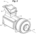
- a chiller system 28 having a condenser section 30, an expansion device 32, an evaporator section 34 and a centrifugal compressor assembly 36 is depicted in an embodiment of the invention.
- the chiller system 28 may be further characterized by a gas bypass circuit 38 and liquid bypass circuit 40 for cooling various components of the centrifugal compressor assembly 36.
- refrigerant within the chiller system 28 is driven from the centrifugal compressor assembly 36 to the condenser section 30, as depicted by the directional arrow 41, setting up a clockwise flow as to FIG. 1 .
- the centrifugal compressor assembly 36 causes a boost in the operating pressure of the condenser section 20, whereas the expansion device 32 causes a drop in the operating pressure of the evaporator section 34. Accordingly, a pressure difference exists during operation of the chiller system 28 wherein the operating pressure of the condenser section 30 may be higher than the operating pressure of the evaporator section 34.
- the centrifugal compressor assembly 36 includes an aerodynamic section 42 having a central axis 44, a motor housing 46, an electronics compartment 48 and an incoming power terminal enclosure 50.
- the motor housing 46 generally defines an interior chamber 49 for containment and mounting of various components of the compressor assembly 36. Coupling between the motor housing 46 and the aerodynamic section 42 may be provided by a flanged interface 51.
- the aerodynamic section 42 of a single stage compressor 43 contains a centrifugal compressor stage 52 that includes a volute insert 56 and an impeller 80 within an impeller housing 57.
- the centrifugal compressor stage 52 may be housed in a discharge housing 54 and in fluid communication with an inlet housing 58.
- the inlet housing 58 may provide an inlet transition 60 between an inlet conduit 59 and an inlet 62 to the compressor stage 52.
- the inlet conduit 59 may be configured for mounting to the inlet transition 50 with a flange 59a.
- the inlet housing 58 can also provide structure for supporting an inlet guide vane assembly 64 and serves to hold the volute insert 56 against the discharge housing 54.
- the volute insert 56 and the discharge housing 54 cooperate to form a diffuser 66 and a volute 68.
- the discharge housing 54 can also be equipped with an exit transition 70 in fluid communication with the volute 68.
- the exit transition 70 can be interfaced with a discharge nozzle 72 that transitions between the discharge housing 54 and a downstream conduit 73 ( FIGS. 3 through 5 ) that leads to the condenser section 30.
- a downstream diffusion system 74 may be operatively coupled with the impeller 80, and may comprise the diffuser 66, the volute 68, transition 70 and the discharge nozzle 72.
- the aerodynamic section 42 can also include a shaft seal 76 and an impeller eye seal 77. The shaft seal 76 may be held in place by a wave spring 78 and retaining ring 79.
- the discharge nozzle 72 may be made from a weldable cast steel such as ASTM A216 grade WCB.
- the various housings 54, 56, 57 and 58 may be fabricated from steel, or from high strength aluminum alloys or light weight alloys to reduce the weight of the compressor assembly 36.
- the flanged interface 51 enables the discharge housing 54 to be mounted to the motor housing 46 with the discharge nozzle 72 selectively positioned relative to the central axis 44.
- the selective positioning of the discharge nozzle 72 enables the aerodynamic section 42 to be connected to the condenser section 30 without resort to excessive lengths of downstream conduit 73 or an excessive number of turns in the downstream conduit 73.
- the reduction in the length and number of turns in the downstream conduit 73 generally results in the reduction of attendant head losses in the chiller system 28, thus promoting more energy efficient operation.
- the selective positioning also enables certain embodiments of the invention to be more readily applied to a variety of evaporator and condenser designs that are better suited to unique discharge angles.
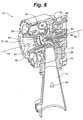
- an impeller 80 can be disposed between the inlet 62 and the diffuser 66 in the impeller housing 57, as depicted in FIGS. 7 and 8 .
- the impeller 80 may include a through bore 81 that enables the impeller 80 to be mounted to a drive shaft such as a motor shaft 82.
- the motor shaft 82 is characterized by a rotational axis 89.
- a tie bolt 84 may be used to couple the impeller 80 to the motor shaft 82.
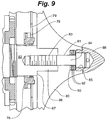
- the tie bolt 84 be engaged with a threaded tap 83, and the cap of the tie bolt 84 seated within a front counterbore 85 on the nose of the impeller 80, as portrayed in FIG. 9 .
- the threaded tap 83 and tie bolt 84 may be of either a left hand or a right hand thread.
- the impeller 80 may also be formed to mate with a protruding portion 86 that extends from a shoulder portion 87 of the motor shaft 82.
- the combination of a flat washer 90 and a spring washer or washers 92 may be implemented in the front counterbore 85 between the tie bolt 84 and the impeller 80.
- a nose cone 88 may be placed over the tie bolt 84 and the front counterbore 85.
- FIGS. 1 through 9 are configured with the impeller 80 coupled directly with the motor shaft 82, thus negating the need for a separate drive shaft and attendant gearing and structure.
- the rotational axis 89 of the motor shaft 82 defines the central axis 44 of the aerodynamic section 42.
- the motor shaft 82 is depicted as having a protruding portion 86 comprising a polygon type mount 96 in an embodiment of the invention.
- the polygon type mount 96 is so named for its polygonal cross-section.
- Other impeller-mounting arrangements may be utilized, including but not limited to a curvic mount or a splined/v-tooth mount.
- the protruding portion 86 of the motor shaft 82 serves to align the impeller 80 with the central axis 44 in one embodiment.
- the spring washers 92 can help keep the tie bolt 84 in tension during operation.
- the choice of a left hand or a right hand thread for the threaded tap 83 and tie bolt 84 may also aid in keeping the tie bolt 84 tightened in the threads of tap 83, depending on the rotational direction of the motor shaft 82.
- the nose cone 88 may be formed with a contoured surface for reduction in the aerodynamic drag as the gas refrigerant 94 enters the impeller 80.
- the nose cone 88 may be used only on the first or inlet stage ( FIG. 10 ).
- the formation of the diffuser 66 and the volute 68 by cooperation of the volute insert 56 with the discharge housing 54 can provide for a reduction in the number of components while enabling aerodynamic flexibility.
- the arrangement enables changes to the aerodynamic components by changing out only the volute insert 56 (e.g. to change the diffuser 66 from a vaneless to a vaned configuration, or changing the passageway characteristics of the volute 68), and may also be suitable for forming the return passages between the first and second stages in a multiple stage aerodynamic section.
- the discharge nozzle 72 and the discharge housing 70 can remain attached to the chiller during servicing of the aerodynamic components.
- the polygon type mount 96 resolves issues associated with the removal, axial location, rotational alignment (i.e. "run-out") and balance of the impeller 80 and eye seal 77.
- the polygon type mount 96 need not be tapered, thus enabling the impeller to rest against a shoulder 87 on the motor shaft 82.
- the polygon type shape can transmit the torque from the motor shaft 82 to the impeller 80 with reduced material stress compared to keyed structures.
- the aerodynamic section 42 transfers angular momentum from the impeller 80 to a gas refrigerant 94 ( FIG. 7 ) entering from the evaporator section 34.
- the kinetic energy imparted by the impeller 80 to the gas refrigerant 94 can be transformed into a higher static pressure in the downstream diffusion system 74.
- the entire total pressure rise in the system is typically generated in the impeller 80.
- Approximately two-thirds of the static pressure rise is typically generated within the impeller 80 itself, with the remaining static pressure rise being generated in the downstream diffusion system 74.
- the discharge nozzle 72 enables greater diffusion of the gas refrigerant 94 before entering the condenser section 30, thereby reducing the total pressure drop into the condenser section and reducing the sound pressure levels radiating from the compressor.
- greater diffusion i.e. pressure recovery or static pressure increase
- the use of weldable cast materials enables the downstream conduit 73 to be welded to the discharge nozzle 72 for installation of a check valve (not depicted) to prevent reverse flow if desired.
- a check valve not depicted
- Other welding-compatible materials may also be utilized for this purpose.
- the connection between the discharge nozzle 72 and the downstream conduit 73 may be a flanged interface (not depicted).
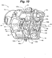
- a multi-stage aerodynamic section 42a for use in a multi-stage compressor is depicted in an embodiment of the invention.
- a multi-stage compressor is characterized as having more than one impeller, depicted in FIG. 10 as a first impeller 80a and a second impeller 80b.
- the first impeller 80a is housed in a first impeller housing 57a that is supported by a spacer insert 98, all defining a first stage 52a.
- a second stage 52b of FIG. 10 is defined by the second impeller 80b, a second impeller housing 57b and the volute insert 56 in the depicted embodiment.
- the first and second stages 52a and 52b may be separated by a crossover channel 99.
- the crossover channel 100 may be equipped with de-swirl vanes (not depicted).
- the first and second stages 52a and 52b and the crossover channel 99 may be housed in a discharge housing 54.
- the inlet housing 58 may be positioned upstream of the first stage 52a.
- a spool or extension 55 may be added to the discharge housing 54, for example, in a flanged arrangement to accommodate both the first and second stages 52a and 52b.
- the discharge housing 54 and extension 55 may be a flangeless, common housing (not depicted) long enough to accommodate both the first and second stages 52a and 52b.
- the first and second impellers 80a and 80b are driven by a common shaft 100.
- the common shaft 100 may be joined to the motor shaft 82 in a variety of ways.
- common shaft 100 may be of a hollow, thick-walled construction and the tie bolt 84 ( FIG. 9 ) lengthened to pass through both the first and second impellers 80a and 80b and the common shaft 100.
- the tie bolt 84 may be the same length as in the single stage configuration of FIG. 9 , but the second impeller is adapted to threadably engage a downstream end 100b of the common shaft 100.
- the latter embodiment may be useful where the axial length of the multi stage aerodynamic section 42a is prohibitively long for a tie bolt 84 of extended length (e.g. where the number of stages exceeds two).
- the downstream impellers are configured with key-ways for imparting the torque to the impellers.
- the common shaft 100 extends to the upstream impeller (e.g. 80a) which can be attached with the tie bolt 84. Spacing between the impellers may be maintained with hollow cylindrical tubes that slide over the common shaft 100.
- a single polygon type mount configuration long enough to support and separate multiple impellers may be utilized.
- the impellers could slide over the polygon type shape, again separated by a hollow cylindrical spacers.
- the invention may be configured with more than two stages. Intermediate stages may be comprised of a spacer insert akin to the spacer insert 98 and an impeller akin to the second impeller 80b. In some embodiments, only the final stage of a multi-stage compressor need be fitted with a volute insert 56.
- the modular construction of the centrifugal compressor assembly 36 enables the aerodynamic section 42 of the single stage compressor 43 ( FIG. 8 ) to be replaced with the multi-stage aerodynamic section 42a as the need arises.
- the modular construction enables the operator to upgrade the unit without replacing the drive train (discussed below) or other components that can be shared by the two configurations (e.g. the inlet housing 58, inlet guide vane assembly (discussed below), volute insert 56, and discharge nozzle 72).
- the modular construction can also simplify the parts inventory fabricated by chiller manufacturers and retained by suppliers. Multiple spools such as the extension 55 ( FIG. 10 ) enable build up of the discharge housing 54 to whatever length is required without need for replacing the housing 54 used in the single stage configuration ( FIG. 8 ).
- the first impeller 80a typically imparts a tangential velocity component on the gas refrigerant 94 as the gas refrigerant 94 enters the crossover channel 99.
- the de-swirl vanes may be designed to remove the tangential velocity component as the gas refrigerant 94 passes through the crossover channel 99, thereby straightening the flow as it enters the second stage 52b.
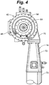
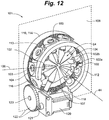
- the inlet guide vane assembly 64 may include a plurality of guide vane subassemblies 102, each mounted to the inlet transition 60. (The inlet transition 60 has been removed from FIG. 12 for clarity.)
- Each guide vane subassembly 102 may include an airfoil portion 102a, a pedestal portion 102b configured to operatively couple with the inlet transition 60, and a gear portion 104.
- the gear portion 104 and pedestal 102b may mate via a key slot 103 arrangement.
- the guide vane subassembly 102 can be configured to rotate about an axis of rotation 106 that substantially intersects the central axis 44.
- the pedestal 102b can be retained in a given radial location relative to the gear portion 104 with a clip ring 105.
- the embodiment depicted includes a plurality of such guide vane subassemblies 102 and gear portions 104, each having their own axis of rotation 106.
- the multiple axes of rotation 106 are substantially located on a control plane 108.
- the guide vane subassemblies 102 may be sized so as not to reach the central axis 44, thus defining a hole or clearance diameter 107 in the center of the inlet guide vane assembly 64.
- the clearance diameter 107 may enable a minimum or threshold flow to prevent stall during light load or start-up.
- the clearance diameter 107 also enables access to the tie bolt 84.
- the gear portions 104 may be fabricated from a polymer.
- polymers such as polyoxy-methylene (POM), also known as polyacetal, paraformaldehyde, acetal resin, polyformaldehyde, and polytrioxane (e.g. DELRIN®, manufactured by DuPont, Inc. of Wilmington, Delaware), enables the gear portions 104 to be formed by injection molding.
- POM polyoxy-methylene
- the guide vane subassemblies 102 may be cast or machined from a silicon-brass or aluminum alloy.
- the embodiment of FIG. 12 depicts a National Advisory Committee for Aeronautics (NACA) series 0009 symmetric airfoil shape for the guide vane subassemblies 102.
- NACA National Advisory Committee for Aeronautics
- a single, ring-shaped face gear 110 that is substantially parallel with and located on the downstream side of the control plane 108 is engaged in mesh with the gear portions 104.
- the ring-shaped face gear 110 can also be fabricated from a high strength polymeric material, such as DELRIN or other class 5 material, in which case the ring-shaped face gear may be injection molded.
- the gear portions 104 may be manufactured from self-lubricating materials that are durable enough to provide acceptable useful life and are resistant to the refrigerant or refrigerants specified for use with the chiller assembly 28.
- self-lubricating materials include, but are not limited to acetals (such as POM), polybutylene teraphthalate (PBT), nylon, polyphenylene sulphide (PPS), liquid crystal polymer (LCP) and polyetheretherketone (PEEK).
- metal cores may be used that are partially or entirely coated with a self-lubricating material on the exterior surfaces or on the gear contact surfaces.
- Acetal possesses dimensional stability, fatigue resistance, and ability to withstand many chemicals over a wide range of temperatures. Acetal is highly lubricious and moves smoothly over both metals and plastics.
- PBT is a polyester suited for application in mixed gear sets having gears made from other plastics and metals and is noted for molding with smooth surfaces. Nylons are generally noted for toughness, wear resistance and low frictional resistance with other plastics and metals.
- PPS is generally stiff and dimensionally stable with high fatigue and chemical resistance. LCPs are noted for dimensional stablility to 220°C and resistance to most chemicals.
- Fibers and fillers may be utilized to enhance gear-resin properties.
- acetal copolymer reinforced with 25% short 2-mm glass fibers can double base resin tensile strength and triple its flexural modulus. Adding glass fibers longer than 10-mm can further enhance polymer strength, stiffness, creep and impact resistance, dimensional stability, and toughness.
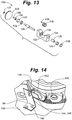
- a guide vane stop ring 112 having a scalloped face 113 is located on the upstream side of the gear portions 104 in an embodiment of the invention, with the scalloped face 113 oriented toward the gear portions 104. See FIGS. 12 and 14 .
- the guide vane stop ring 112 may also be fabricated from polyoxy-methylene enabling fabrication by injection molding, or other high strength polymeric materials. Location of the ring-shaped face gear 110 and the guide vane stop ring 112 relative to the control plane 108 (i.e. upstream or downstream) is arbitrary and non-limiting.
- the depicted embodiment illustrates the ring-shaped face gear 110 as having an outer periphery 114, a portion of which is machined as a worm gear 116 to mate with a worm 118.
- the worm 118 can be driven by a drive motor 120 through a standard drive / speed reduction gear combination 122 comprising a drive gear 121 and a speed reduction gear 123.
- the inlet guide vane assembly 64 may be used to set the inlet swirl angle either with or against the rotational direction of impeller 80. By varying the inlet guide vane angle, the work, pressure rise, and mass flow of refrigerant through the compressor stage can be controlled.
- the inlet guide vane assembly 64 can thus provide controlling or throttling flow of gas the refrigerant 94 through centrifugal compressor assembly 36 when operating at a partial cooling load. (Another technique involves varying the compressor speed, discussed below, which may be used in combination with the inlet guide vane assembly 64 to control the centrifugal compressor assembly 36.)
- the use of self lubricating materials for the gear portions 104 inlet guide vane assembly 64 may also be designed to work in a refrigerant environment without need of lubrication oil.
- the worm assembly 126 comprises a shaft 128, the worm 118, a long spacer 129, as short spacer 130, and two bearings 131 and 132 disposed near the ends of the shaft 128, all mounted in a worm support bracket 133.
- the worm support bracket 133 can be substantially U-shaped with a first port 134 in substantial axial alignment with a second port 135.
- the first port 134 can be configured to accept a spring washer 136, and the second port 135 configured to accept a retaining clip 137.
- the shaft 128 may be configured to accept a retention clip 127 at one end and gear keys 138 and 139 that mate with the worm 118 and the speed reduction gear 123, respectively.
- the spacers 129, 130 are used to place the worm 118 in the proper orientation within the worm support bracket 133 in the depicted embodiment of FIG. 13 .
- the bearings 131, 132 may provide free rotation of the shaft 128 that reduce friction and torque requirements when compared with standard contact or roller bearing designs.
- the worm assembly 126 can be held within the worm support bracket 133 by the opposing retention provided by the spring washer 136 and the retaining clip 137.
- the retention clip 127 may secure the speed reduction gear 123 between the end of the shaft 128 and the worm support bracket 133.
- the gear keys 138 and 139 may function to rotationally secure the worm 118 and the speed reduction gear 123, respectively.
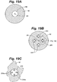
- a position sensor 140 for determining the angular position of the inlet guide vane subassemblies 102 is illustrated in an embodiment of the invention.
- Suitable position sensors are commercially available, such as the MLX 90316, manufactured by Melexis Microelectronic Integrated Systems of Concord, New Hampshire.
- the position sensor 140 operates on a magnetic Hall effect principle, wherein a magnet 142 is embedded at or otherwise coupled to the base of the guide vane subassembly 102, and a Hall effect sensor 144 mounted on a circuit board 146 in close proximity to magnet 142 to sense the position of the magnet 142 about the axis of rotation 106.
- the angular position of the guide vane subassembly 102 may be derived from the sensed position of the magnet 142.
- the circuit board 146 may be supported by a bracket 148 mounted to the inlet housing 58.
- a description of the operation of the MLX 90316 is provided in "MLX90316 Rotary Position Sensor IC,” 3901090316 Rev. 001 Data Sheet, 04 October 2005, which is hereby incorporated by reference herein other than any express definitions of terms specifically defined therein.
- the centrifugal compressor assembly 36 can be controlled by rotationally positioning the inlet guide vane subassemblies 102 to obstruct and/or direct flow to various degrees.
- the drive motor 120 rotates the worm 118 through the drive / speed reduction gear combination 122, which drives the worm gear 116 and causes the face gear 110 to rotate about central axis 44.
- the rotation of the face gear 110 in this embodiment causes each of the gear portions 104 to rotate about the respective axis of rotation 106, thereby rotating the guide vane subassembly 102.
- the bearings 134 and 136 may provide free rotation of the shaft 128 for low friction and torque requirements.
- the scalloped face 113 of the guide vane stop ring 112 ( FIG. 12 ) can provide a mechanical stop for the rotation of each of the gear portions 104 in both the open and closed directions, thereby preventing damaging collisions between the guide vane subassemblies 102.
- Other means for a mechanical stop may be used such as pins or protrusions that extend from the inlet housing 58.
- the drive motor 120 may be a hermetic bi-directional stepper motor with an internal feedback loop, from which the angular position of guide vane subassemblies 102 may be determined through proper alignment and calibration.
- the drive motor 120 may be sized to deliver the necessary torque to drive the guide vane subassemblies 102 from a fully closed position to a fully open position.
- the drive motor 120 can also be sized to handle loads imposed by the aerodynamic force of a refrigerant gas 124 over the guide vane subassemblies 102 during operation.
- the drive motor 120 can be configured so that the guide vane subassemblies 102 can be held in a constant rotational position and prevented from drifting during operation.
- the position sensor assembly 140 offers an alternative embodiment for determination of the angular orientation of the guide vane subassembly 102.
- the output signal of the Hall effect sensor 144 varies according to the angular position of a magnet 142 that that may be mounted to the end of the inlet guide vane subassembly 102.
- the circuit board 146 can provide connection points for signal cables (not shown) and a mounting structure for the Hall effect sensor 144.
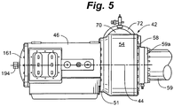
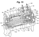
- a drive train 150 that includes a permanent magnet motor 152 having a stator assembly 154, a rotor assembly 156 mounted to a motor shaft 82, and oil-free, magnetic bearings 158 and 160 that suspend the motor shaft 82 during operation.
- the permanent magnet motor 152 may be powered through six leads 162 connected to the stator assembly 154 via a terminal bus plate assembly 163.
- a rotational position feedback device such as an encoder or potentiometer that detects the shaft position may also be coupled to the motor shaft 82.
- the motor housing 46 and the drive train 150 may further include an end housing 161, a pair of bearing carrier subassemblies 149a and 149b, and a thrust bearing assembly 151.
- the thrust bearing assembly can include a runner 151a extending radially outward from the motor shaft 82 and two coils 151b and 151c that straddle the runner 151a.
- the coils 151b and 151c of the thrust bearing assembly 150 magnetically interact with the runner 151a to secure the drive train 150 at an axial position within the motor housing 46, thereby providing a frictionless counterforce to forward and reverse thrust forces that are exerted on the drive train 150.
- the bearing carrier subassemblies 149a and 149b can provide structure for positioning the bearings on the motor center line after the motor is installed.
- the position feed back device may be used to determine the rotational speed of the motor shaft 82, as well as the rotational position at a given instant, both of which may be required for proper operation and control of a variable frequency drive.
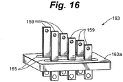
- the terminal bus plate assembly 163 is presented in perspective in an embodiment of the invention.
- six rectangular terminals 159 pass through a dielectric potting material 165 such as a glass epoxy material.
- the terminals 159 can be grouped in two sets of three, with each set passing through a common dielectric potting.
- the potting material 165 provides electrical insulation between the terminals 159 and the mounting plate 163a.
- each terminal 159 is individually potted within a dielectric feedthrough 167 fitted with a means such as an o-ring or a compression seals to seal to the dielectric feedthrough 167 to prevent leakage between the dielectric feedthrough 167 and the mounting plate 163a of the gas refrigerant 94 contained in the motor housing 46.
- a means such as an o-ring or a compression seals to seal to the dielectric feedthrough 167 to prevent leakage between the dielectric feedthrough 167 and the mounting plate 163a of the gas refrigerant 94 contained in the motor housing 46.
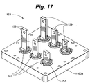
- Each terminal 159 and corresponding dielectric feedthrough 167 forms an assembly that can be removed individually and may be retained by snap rings 157 as depicted in FIG. 17 , or by other configurations available to the skilled artisan, such as threaded connections or lock nuts.
- the terminals 159 in the configurations of FIGS. 16 and 17 are typically fabricated from copper and may vary in height to facilitate the installation of power wires onto the terminals.
- the mounting plate 163a may be constructed from aluminum, an aluminum alloy or other suitable structural material.
- a rotor assembly 156 is portrayed in an embodiment of the invention.
- the motor shaft 82 includes a drive end 164 upon which the impeller 80 can be mounted, and a non-drive end 166 which extends into the motor housing 46.
- the rotor assembly 156 may be characterized by an internal clearance diameter 168 and an overall length 170 which may include an active length 172 over which a permanent magnetic material 174 can be deposited.
- a 6-phase stator assembly 154 is also depicted in FIG. 18 in an embodiment of the invention.
- the stator assembly 154 is generally described as a hollow cylinder 176, with the walls of the cylinder comprising a lamination stack 178 and six windings 180 having end turn portions 181 and 182 encapsulated in a dielectric casting 183 such as a high temperature epoxy resin (best illustrated in FIG. 18 ).
- a total of six leads 162 (four of which are shown in FIG. 18 ), one for each of the six windings 180, extend from an end 186 of the hollow cylinder 176 in this configuration.
- a sleeve 188 may be included that extends over the outer surface of the hollow cylinder 176 and in intimate contact with the outer radial peripheries of both the lamination stack 178 and the dielectric castings 183.
- the sleeve 188 may be fabricated from a high conductivity, non-magnetic material such as aluminum, or stainless steel.
- a plurality of temperature sensors 190 such as thermocouples or thermisters, may be positioned to sense the temperature of the stator assembly 154 with terminations extending from the end 186 of the hollow cylinder 176.
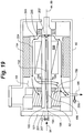
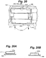
- a rotor cooling circuit 192 is illustrated in an embodiment of the invention.
- the rotor cooling circuit 192 may be a subpart or branch of the gas bypass circuit 40 ( FIG. 1 ).
- Refrigerant gas 94 from the evaporator section 34 may enter the rotor cooling circuit 192 through an inlet passage 194 formed on the end housing 161 and may exit via an outlet passage 195 formed on the motor housing 46.
- the rotor cooling circuit 192 may be defined as the segment of the gas bypass circuit 40 between the inlet passage 194 and the outlet passage 195.
- the inlet passage 194 may be in fluid communication with a longitudinal passage 196 that may be a center passage substantially concentric with the rotational axis 89 of the motor shaft 82.
- the longitudinal passage 196 may be configured with an open end 198 at the non drive end 166 of the motor shaft 82.
- the longitudinal passage 196 may pass through and beyond the portion of the motor shaft 82 upon which the rotor assembly 156 is mounted, and terminate at a closed end 200.
- FIG. 19 portrays a gap 201 between the non drive end 166 of the motor shaft 82 and the end housing 161.
- refrigerant gas 94 is drawn into the open end 198 of the longitudinal passage 196 from the interior chamber 94.
- the shaft may contact cooperating structures on the end housing 161, such as dynamic seals, so that the refrigerant gas 94 is ducted directly into the longitudinal passage 196.
- a plurality of radial aspiration passages 202 are in fluid communication with the longitudinal passage 196 near the closed end 200, the aspiration passages 202 extending radially outward through the motor shaft 82.
- the aspiration passages 202 may be configured so that the gas refrigerant 94 exits into a cavity region 203 between the stator assembly 154 and the motor shaft 82.
- An annular gap 204 may be defined between the stator assembly 154 and the rotor assembly 156 to transfer the refrigerant gas 94.
- the rotor cooling circuit 192 of the gas bypass circuit 40 may be arranged to enable refrigerant gas to course over the various components housed between the rotor assembly 156 and the end housing 161 (e.g.
- the gas refrigerant 94 exiting the outlet passage 195 may be returned to the evaporator section 34.
- components of the drive train 150 are in contact with cooling refrigerant in a vapor phase (gas refrigerant 94), and, under certain conditions, with refrigerant in a liquid phase.
- a plurality of flow passages 206 are depicted that are substantially parallel with but not concentric with the rotational axis 89 of the motor shaft 82 in another embodiment of the invention.
- the flow passages 206 may replace the single longitudinal passage 196 of FIG. 19A as depicted, or may supplement the longitudinal passage 196.
- the plurality of passages may be in fluid communication with the aspiration passages 202.
- the flow passages 206 may also include heat transfer enhancement structures, such as longitudinal fins 206a that extend along the length of and protrude into the flow passages 206.
- heat transfer enhancement structures are available to the artisan, including but not limited to spiral fins, longitudinal or spiraled (rifling) grooves formed on the walls of the flow passages 206, or staggered structures.
- Such heat transfer enhancement structures may also be incorporated into the configuration of FIGS. 19 and 19A .
- the use of the plurality of passages may enhance the overall heat transfer coefficient between the gas refrigerant 94 and the rotor assembly 156 by increasing the heat transfer area.
- the heat transfer enhancement structures may also increase the heat transfer area, and in certain configurations can act to trip the flow to further enhance the heat transfer.
- the conductive coupling between the flow passages 206 and the outer surface of the motor shaft 82 may also be reduced because the effective radial thickness of the conduction path may be shortened.
- the multiple passages may further provide the designer another set of parameters that can be manipulated or optimized to produce favorable Reynolds number regimes that enhance the convective heat transfer coefficient between the gas refrigerant 94 and the walls of the flow passages 206.
- a throttling device 207 may be included on the inlet side (as depicted in FIG. 19 ) or the outlet side of the rotor cooling circuit 192 of the gas bypass circuit 40.
- the throttling device 207 may be passive or automatic in nature.
- a passive device is generally one that has no active feedback control, such as with a fixed orifice device or with a variable orifice device that utilizes open loop control.
- An automatic device is one that utilizes a feedback element in closed loop control, such as an on/off controller or a controller that utilizes proportional/integral/derivative control schemes.
- the temperature of the gas refrigerant 94 exiting the rotor cooling circuit 192 may be monitored with a feedback element such as a temperature sensing probe 205.
- the feedback element may be used for closed loop control of the throttling device 207.
- other feedback elements may be utilized, such as a flow meter, heat flux gauge or pressure sensor.
- the stator cooling section 208 may comprise a tubing 209a that defines a spiral passageway 210 formed on the exterior of the sleeve 188. Heat transfer to the refrigerant 216 flowing in the tubing 209a may be augmented with a thermally conductive interstitial material 211 between the tubing 209a and the sleeve 188.
- the tubing 209a may be secured to the sleeve 188 by welding, brazing, clamping or other means known to the artisan.
- the spiral passageway 210 may comprise a channel 209b that enables a liquid refrigerant 216 flowing therein to make direct contact with the sleeve 188.
- the channel 209b may be secured to the sleeve 188 by welding, brazing or other techniques known to the artisan that provide a leak tight passageway.
- the invention is not limited to a spiral configuration for the stator cooling section 208.
- Conventional cylindrical cooling jackets such as the PANELCOIL line of products provided by Dean Products, Inc. of Lafayette Hill, Pennsylvania, may be mounted onto the sleeve 188, or even supplant the need for a separate sleeve.
- the spiral passageway 210 can be configured for fluid communication with a liquid cooling inlet port 212 through which the refrigerant liquid 216 is supplied and a liquid cooling outlet port 214 through which the refrigerant liquid 216 is returned.
- the liquid cooling inlet port 212 may be connected to the condenser section 30 of the refrigeration circuit, and the liquid cooling outlet port 214 may be connected to the evaporator section 34.
- the refrigerant liquid 216 in this embodiment is motivated to pass from the condenser section 30 to the evaporator section 34 ( FIG. 1 ) because of the higher operating pressure of the condenser 30 section relative to the evaporator section 34.
- a throttling device may be included on the inlet side or the outlet side of the stator cooling section 208.
- the throttling device may be passive or automatic in nature.
- the drive train 150 may be assembled from the non drive end 166 of the motor shaft 82. Sliding the rotor assembly 156 over the non drive end 166 during assembly (and not the drive end 164) may prevent damage to the radial aspiration passages 202.
- the permanent magnet motor 152 may have a high efficiency over wide operating range at high speeds, and combine the benefits of high output power and an improved power factor when compared with induction type motors of comparable size.
- the permanent magnet motor 152 also occupies a small volume or footprint, thereby providing a high power density and a high power-to-weight ratio.
- the motor shaft 82 may serve as a direct coupling between the permanent magnet motor 152 and the impeller 80 of the aerodynamic section 42. This type of arrangement is herein referred to as a "direct drive" configuration.
- the direct coupling between the motor shaft and the impeller 80 eliminates intermediate gearing that introduces transfer inefficiencies, requires maintenance and adds weight to the unit.
- Those skilled in the art will recognize that certain aspects of the disclosure can be applied to configurations including a drive shaft that is separate and distinct from the motor shaft 82.
- the rotation of radial aspiration passages 202 within the motor shaft 82 acts as a centrifugal impeller that draws the gas refrigerant 94 through the gas bypass circuit 40 and cools the stator assembly 154.
- gas residing in the aspiration passages 202 is thrown radially outward into the cavity 203, thereby creating a lower pressure or suction at the closed end 200 that draws the refrigerant gas 94 through the inlet passage 194 from the evaporator section 34.
- the displacement of the gas into the cavity 203 also creates and a higher pressure in the cavity 203 that drives the gas refrigerant 94 through the annular gap 204 and the outlet passage 195, returning to the evaporator section 34.
- the pressure difference caused by this centrifugal action causes the refrigerant gas 94 to flow to and from the evaporator section 34.
- the cooling of the rotor assembly 156 may be enhanced in several respects over existing refrigeration compressor designs.
- the rotor assembly 156 is cooled along the length of the internal clearance diameter 168 by direct thermal conduction to the cooled motor shaft 82.
- the outer surface of the rotor assembly 156 is also cooled by the forced convection caused by the gas refrigerant 94 being pushed through the annular gap 204.
- the throttling device 207 may be used to control the flow of gas refrigerant 94 and the attendant heat transfer thereto.
- the temperature sensing probe 205 may be utilized as a feedback element in the control of the flow rate of the refrigerant gas 94.
- the use of the refrigerant gas 94 has certain advantages over the use of the refrigerant liquid 216 for cooling the rotor.
- a gas typically has a lower viscosity than a liquid, thus imparting less friction or aerodynamic drag over a moving surface. Aerodynamic drag reduces the efficiency of the unit. In the embodiments disclosed, aerodynamic drag can be especially prevalent in the flow through the annular gap 204 where there is not only an axial velocity component but a large tangential velocity component due to the high speed rotation of the rotor assembly 156.
- the stator assembly 154 may be cooled by the liquid refrigerant 216 that enters the spiral passageway 210 as a liquid. However, as the liquid refrigerant 216 courses through the stator cooling section 208, a portion of the refrigerant may become vaporized, creating a two phase or nucleate boiling scenario and providing very effective heat transfer.
- the liquid refrigerant 216 may be forced through the liquid bypass circuit 40 and the stator cooling section 208 because of the pressure differential that exists between the condenser section 30 and the evaporator section 34.
- the throttling device (not depicted) passively or actively reduces or regulates the flow through the liquid bypass circuit 40.
- the temperature sensors 190 may be utilized in a feedback control loop in conjunction with the throttling means.
- the sleeve 188 may be fabricated from a high thermal conductivity material that thermally diffuses the conductive heat transfer and promotes uniform cooling of the outer peripheries of both the lamination stack 178 and the dielectric castings 183.
- the sleeve 188 further serves as a barrier that prevents the liquid refrigerant 216 from penetrating the lamination stack 178.
- the encapsulation of the end turn portions 181, 182 of the stator assembly 154 within the dielectric castings 183 serves to conduct heat from the end turn portions 181, 182 to the stator cooling section 208, thereby reducing the thermal load requirements on the rotor cooling circuit 192 of the gas bypass circuit 40.
- the dielectric casting 183 can also reduce the potential for erosion of the end turn portions 181, 182 exposed to the flow of the gas refrigerant 94 through the rotor cooling circuit 192.
- the rotor assembly 156 is supported by frictionless magnetic bearings 158 and 160 under normal operation.
- the bearings 158, 160 are controlled and levitated by microprocessor controllers and power amplifiers which may be contained within an electronics enclosure 217 on the compressor body or located remotely.
- backup rolling element bearings 218 and 220 may be provided to constrain the rotating assembly and protect it from damage during a catastrophic control failure of the magnetic bearings 158 and 160.
- the backup bearings 218 and 220 have an inner diameter that is greater than the diameter of the motor shaft 82.
- the magnetic bearings 158 and 160, backup bearings 218 and 220 and motor shaft 82 may be arranged so that the motor shaft 82 is substantially centered within the inner diameter during operation, creating an annular gap between the motor shaft 82 and each of the magnetic bearings 158 and 160. The gaps enable the motor shaft 82 to rotate freely without contacting the backup bearings 218, 220. By this arrangement, the backup bearings 218, 220 do not contact the rotor assembly 156 during normal operation.
- VFD system variable frequency drive system
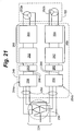
- a total of six power leads 250 transmit power to a pair of three-phase windings 252a and 252b.
- Each set of three-phase windings 252a and 252b may be powered by a separate and independent variable frequency drive (VFD) power section 254a and 254b that may be sourced through an autotransformer 256 connected to a mains supply 224.
- VFD variable frequency drive
- the autotransformer 256 may provide a 30-degree phase shift between the VFD power sections 254a or 254b.
- the autotransformer 256 can also be used to raise or lower the incoming voltage as required according to the demands of the VFD.
- the six-phase embodiment is depicted and described herein, but the invention is not limited thereby.
- a single power section could provide power for a permanent magnet motor having one set of 3-phase windings.
- the autotransformer 256 is not used for phase shifting but may be used to raise or lower the incoming voltage to that required by the VFD power section 254a and 254b.
- the VFD power sections 254a and 254b may each comprise an input rectifier 258, a filter 260, a current chopper 262 and a steering circuit 264, all connected through a DC bus 266 as depicted in FIG. 21 .
- the rectifier 258 converts the AC power from the autotransformer 256 to a DC power.
- the types of rectifiers that may be utilized include a diode bridge, a thyrister controlled rectifier, or a combination thereof.
- the filter 260 reduces the ripple of the rectified DC power.
- the current chopper 262 and steering circuit 264 combine to form an inverter 268.
- the inverter 268 converts the DC power to a 3-phase AC power at a frequency corresponding to a desired rotational speed of the permanent magnet motor 153.
- the switching of the currents on the DC bus 266 is accomplished with insulated gate bipolar transistors (IGBTs) using pulse width modulation (PWM).
- IGBTs insulated gate bipolar transistors
- PWM pulse width modulation
- the inverter 268 is referred to as a "current source” type wherein the output to the permanent magnet motor 153 is a controlled AC current rather than a controlled AC voltage.
- Current source drives can be seen in references such as " Introduction to Power Electronics and Drives," Bimal K. Bose, ed. Ch5, 1997, Institute of Electrical and Electronics Engineers, ISBN0-7803-1061-6 which is hereby incorporated by reference other than any express definitions of terms specifically defined therein.
- the power electronics, control methods, and microprocessor controls enable users to take advantage of the benefits of a current source drive with few of the drawbacks.
- the current source inverter uses a lower switching frequency in the inverter and lower voltage rise time (dV/dT), thereby reducing motor stress and improving overall system efficiency.
- the current source inverter also has inherent current-limiting abilities.
- Current source inverters typically include large inductors in the DC link with attendant cost and weight.
- Current control methods may be quite sophisticated for control of harmonics on the input and output.
- a function of the current chopper 262 in various embodiments is to maintain the DC bus voltage at the proper level above the back-emf of the permanent magnet motor 153 and to maintain a constant current source for the permanent magnet motor 153.
- the current chopper 262 may comprise a network of diodes, large inductors, and switching devices.
- the switching devices may be a plurality of insulated gate bipolar transistors (IGBTs) that are arranged in parallel and are controlled in an interleaved or multi-phase pattern. This control pattern switches the IGBTs "on" at different points in time which reduces the ripple in the DC link and smoothes the current supply.
- IGBTs insulated gate bipolar transistors
- the steering circuit 264 may include a network of switching devices that convert the DC power to a pulsed, 3-phase AC power using a PWM control pattern.
- the power to the respective 3-phase winding 252a or 252b of the permanent magnet motor 153 may be switched at a rate according to the desired motor speed.
- This type of inverter output section can use a much lower switching frequency as compared to a voltage source drive.
- Another embodiment of this invention uses a voltage source inverter.
- the DC voltage is maintained and the IGBTs switch at a higher rate.
- the VFD system 248 may be matched to provide sufficient torque and speed for the centrifugal impeller 80 or impellers 80a and 80b to meet the operational requirements of the chiller.
- the VFD system 248 may reduce power line harmonics and enhance drive train efficiency over conventional designs.
- the use of two VFD power sections 254a and 254b to feed independent windings in the motor negates the need to coordinate the DC bus voltage or current using an interphase transformer as with traditional 12-pulse VFDs. The arrangement also reduces motor heating and energy losses.
- the VFD system 248 may be designed for high speed operation to accommodate a range of impeller size and refrigerant combinations that may be implemented in the modular design of the invention. Rotational speeds in excess of 20,000 rpm are attainable.
- the VFD system 248 includes heat sinks having a cooling bypass circuit (not depicted) that accommodates a liquid or a gas refrigerant.
- the cooling bypass circuit may include a control valve and a feedback temperature element from the heat sink to control the heat sink at a desired temperature (not depicted).
- the wetted components of the heat sink may be selected for compatibility with the refrigerant to be used (e.g. refrigerant R-134a and polyolester oil). Electronics in close proximity to actively cooled components may be designed to avoid or accommodate moisture from condensation.
- Various embodiments may use water as the cooling fluid.
- the rectifiers 258 may generate harmonics that may cause a variety of maladies not only to the plant equipment, but to neighboring facilities via the power grid that feed the mains supply 224, particularly for high power installations.
- the problems potentially caused by harmonics include conductor overheating, failure or rupture of capacitors, spurious tripping of breakers, overheating of transformer windings, as well as interference with controllers, computers and utility meters in a facility or on the power grid.
- the 30-degree phase shift provided by the autotransformer 256 can mitigate these issues by reducing attendant power line harmonics and providing a 12-pulse input to the inverters (e.g. 6 pulses to each of the two inverters 268 of FIG. 21 ).
- the 12-pulse input may eliminate the 5 th and 7 th harmonics.
- the phase shifting in the 6-phase motor configuration may reduce motor heating and maximize efficiency.
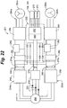
- a power supply and VFD system 221 including an intermediate power supply 222 that drives the magnetic bearings 158 and 160, a magnetic bearing controller 270 and a VFD controller 272 is depicted in an embodiment of the invention.
- the intermediate power supply 222 may be sourced by DC-link voltages 274a and 274b from the DC buses 266 of each VFD 254a and 254b.
- An additional DC input 276 to the intermediate power supply 222 may also be derived through a rectifier 278 from the incoming mains supply 224.
- the intermediate power supply 222 includes a switching converter 280 and a bank of isolating power supply transformers 282 to convert the DC-input 276 or the intermediate DC-link voltage 274 to a specified auxiliary supply voltage.
- the magnetic bearings 158 and 160, the magnetic bearing controller 270, and the VFD controller 272 may be connected to the appropriate isolating power supply transformers 282.
- Various embodiments of the invention may also source the intermediate power supply 222 with back-emf voltages 284a and 284b provided by the revolution of the respective 3-phase winding 252a or 252b of the permanent magnet motor 153.
- the back-emf voltages 284a and 284b may be the only power source present on the DC buses 266 in the event of an interruption of power from the mains supply 224.
- the back-emf voltages 284a and 284b are generally proportional to the rotational speed of the permanent magnet motor 153.
- redundant sources for the intermediate power supply 222 enables functional energization of the compressor assembly without the DC-link voltages 274a and 274b being present.
- the intermediate power supply may be source through the rectifier 278 when the VFDs are not fully powered or when there is no back-emf voltage present, such as during initial system start up or servicing of the system.
- the back-emf voltages 284a and 284b may provide an alternative power source to the intermediate power supply 222.
- Such redundancy provides additional security of supply not only to the magnetic bearings 158, 160, but also to the magnetic bearing controller 270 in the event that failure of the VFDs 254a and 254b result in the loss of the DC-link voltages 274a and 274b.
- the AC voltages put out by the inverters 268 may be controlled to be just above the back emf voltages 284a and 284b produced by the permanent magnet motor 153.
- Phase timing for the switching of the IGBTs in the inverters 268 may be accomplished with a rotational position feedback device feedback device.
- the DC-link voltages 274a and 274b may be maintained by the back-emf voltages 284a and 284b.
- the back-emf passes through diodes arranged in a "freewheel" configuration that are applied in parallel with the IGBT switching devices. In this configuration, the freewheel diodes act as a rectifier to supply the DC bus.
- the power to the magnetic bearings 158, 160 and magnetic bearing controller 270 can thereby be maintained during transients and line dips experienced by the mains supply 224 to prevent damage to the magnetic bearings 158, 160.
- the VFDs 254a and 254b may be configured to operate at a variety of standard mains supply voltages (e.g. 380, 400, 415, 440, 460, 480 and 575V) with appropriate variations (e.g. ⁇ 10%) and at 50 or 60Hz line frequency.
- the accommodation of the variety of input voltages can generate a wide range of DC-link voltages 274a, 274b.
- the ability to operate at reduced voltage and frequency imposes a further variable on the DC-link voltage 274 delivered to the intermediate power supply 222. Accordingly, some level of regulation may be utilized in delivering power to the bearings 158, 160 and controllers 270 and 272.
- the VFD controller 272 may enable the VFD system 248 to spin the permanent magnet motor 152 and communicate the status of the VFD system 248 to other components of the chiller system.
- the VFD system 248 may be configured to transmit and receive setup and operating data over an Ethernet network local to the chiller installation. Also, the VFD system 248 may have an FTP server to upload software updates over the Ethernet network and an HTTP server to monitor and set up the drive.
- the intermediate power supply 222 may be further configured to provide a "regenerative boost" 286 to the DC-link voltages 274a and 274b.
- the regenerative boost 286 may be achieved by revising the switching regime of the IGBTs in the output inverter of the VFD 264. Maintaining the DC link voltages 274a and 274b also, in turn, maintains the output voltage from the intermediate power supply 222.
- the boost can be accomplished by adjusting the inverter switching pattern to simulate a "boost" converter.
- the output voltage exceeds the input voltage due to the circuit arrangement including the DC link inductors (energy storage device), diodes, and IGBTs.
- FIG. 23 An example effect of the regenerative boost 286 is presented in FIG. 23 as a normalized graph of the DC-link voltage 274 and a rotational speed 290 of the permanent magnet electric motor 153.
- the dashed line represents a non-boosted voltage 288 of the DC-link voltage 274 that occurs without the regenerative boost 286.
- the non-boosted voltage 288 drops proportionally with speed.
- the output of the intermediate power supply 222 may thereby be maintained down to approximately 5% rated rotational speed 290 of the permanent magnet motor 153.
- the DC-link voltage 274 of the regenerative boost configuration is represented by the solid line 286.
- the effect of the regenerative boost can be realized at rotational speeds 290 below approximately 40% of rating, whereas the DC-link voltage 274 may be maintained constant until the rotational speed 290 drops below approximately 2% of rated. Below 2% of rated rotational speed 290, the DC-link voltage 274 drops off sharply, reaching a zero output at approximately 1% of the rated rotational speed.
- the regenerative boost may be configured to provide enough DC-link voltage 274 above a threshold that maintains the controllers 270 and 272 down to a rotational speed 290 that is near zero and, depending on the rated DC-link voltage, could also provide adequate power or voltage above a threshold value that maintains the magnetic bearings 158, 160 down to the same rotational speed 290.
- the backup bearings 218, 220 can support the rotating assembly if there is any residual rotational speed after an abnormal a loss of bearing control. Under normal shutdown conditions, the bearing controller may bring the motor shaft 82 to a complete stop prior to lowering the motor shaft 82 onto the backup bearings 218, 220.
- a procedure for assembling the motor/ bearing assembly in an embodiment of the invention may be as follows.
- the aerodynamic section 42 may be designed for servicing with the discharge housing 54 attached to the motor housing 46, allowing the discharge nozzle 72 to remain in place during servicing of the aerodynamic section 42 and thereby reducing servicing downtime.
- the discharge housing 54 can be rotated about the central axis 44 to provide flexibility in assembling the centrifugal compressor assembly 36. See FIG. 6 .
- a procedure for installing the impeller 80 onto the motor shaft 82 in accordance with the configuration depicted in FIG. 9 may be as follows:
- Assembly of the centrifugal compressor assembly 36 may be achieved through the following procedures:
- Assembly of a multi-stage aerodynamic section would follow a similar method and can be applied to a nearly identical drive train with variations in shaft length and bearing loads.
- a procedure for assembling the worm assembly 126 may be as follows (please refer to FIG. 13 ):
- a procedure for assembling the inlet guide vane assembly 64 can be as follows (please refer to FIG. 12 ):
Landscapes
- Engineering & Computer Science (AREA)
- General Engineering & Computer Science (AREA)
- Mechanical Engineering (AREA)
- Power Engineering (AREA)
- Physics & Mathematics (AREA)
- Thermal Sciences (AREA)
- Microelectronics & Electronic Packaging (AREA)
- Electromagnetism (AREA)
- Structures Of Non-Positive Displacement Pumps (AREA)
- Magnetic Bearings And Hydrostatic Bearings (AREA)
- Connection Of Motors, Electrical Generators, Mechanical Devices, And The Like (AREA)
Claims (6)
- Système de refroidissement (28), comprenant:un ensemble de compresseur centrifuge (36) pour comprimer un gaz réfrigérant, comprenant un moteur à aimant permanent, ledit moteur à aimant permanent étant logé à l'intérieur d'un carter de moteur (46), ledit carter de moteur (46) définissant une chambre intérieure (49), ledit moteur à aimant permanent comprenant:un arbre de moteur (82) rotatif autour d'un axe de rotation,un ensemble de rotor (156) couplé de façon opérationnelle à une partie dudit arbre de moteur (82), etcaractérisé par au moins deux paliers magnétiques (158, 160) couplés de façon opérationnelle audit arbre de moteur (82), ledit arbre de moteur (82) comprenant au moins un passage longitudinal (196) et au moins un passage d'aspiration (202), ledit au moins un passage longitudinal (196) s'étendant sensiblement parallèlement audit axe de rotation à travers au moins ladite partie dudit arbre de moteur (82), ledit au moins un passage d'aspiration (202) étant en communication fluidique avec ladite chambre intérieure (49) et ledit au moins un passage longitudinal (196); etune section d'évaporateur (34) en communication fluidique avec ledit au moins un passage longitudinal (196) pour fournir ledit gaz réfrigérant qui refroidit ledit arbre de moteur (82) et ledit ensemble de rotor (156) .
- Système de refroidissement (28) selon la revendication 1, comprenant en outre une section aérodynamique (42) couplé de façon opérationnelle audit arbre de moteur (82).
- Système de refroidissement (28) selon la revendication 2, dans lequel ladite section aérodynamique (42) et ledit arbre de moteur (82) sont directement couplés.
- Système de refroidissement (28) selon la revendication 1, dans lequel ledit moteur à aimant permanent dépasse 140 kilowatts de puissance.
- Système de refroidissement (28) selon la revendication 4, dans lequel ladite vitesse de rotation dudit moteur à aimant permanent dépasse 11000 tours par minute.
- Système de refroidissement (28) selon la revendication 1, dans lequel ledit système de refroidissement (28) présente une capacité de refroidissement qui dépasse 703 kW (200 tonnes de réfrigération standard).
Applications Claiming Priority (3)
| Application Number | Priority Date | Filing Date | Title |
|---|---|---|---|
| US84986506P | 2006-10-06 | 2006-10-06 | |
| US11/868,341 US8156757B2 (en) | 2006-10-06 | 2007-10-05 | High capacity chiller compressor |
| PCT/US2007/021536 WO2008045413A2 (fr) | 2006-10-06 | 2007-10-09 | Compresseur frigorifique haute capacité |
Publications (4)
| Publication Number | Publication Date |
|---|---|
| EP2061998A2 EP2061998A2 (fr) | 2009-05-27 |
| EP2061998A4 EP2061998A4 (fr) | 2013-08-28 |
| EP2061998B1 EP2061998B1 (fr) | 2017-12-06 |
| EP2061998B2 true EP2061998B2 (fr) | 2020-12-02 |
Family
ID=39283420
Family Applications (1)
| Application Number | Title | Priority Date | Filing Date |
|---|---|---|---|
| EP07839361.8A Active EP2061998B2 (fr) | 2006-10-06 | 2007-10-09 | Compresseur frigorifique haute capacité |
Country Status (8)
| Country | Link |
|---|---|
| US (1) | US8156757B2 (fr) |
| EP (1) | EP2061998B2 (fr) |
| JP (1) | JP4971454B2 (fr) |
| CN (1) | CN101558268B (fr) |
| AU (1) | AU2007307051B2 (fr) |
| CA (1) | CA2665492C (fr) |
| ES (1) | ES2658939T5 (fr) |
| WO (1) | WO2008045413A2 (fr) |
Families Citing this family (109)
| Publication number | Priority date | Publication date | Assignee | Title |
|---|---|---|---|---|
| US8463441B2 (en) | 2002-12-09 | 2013-06-11 | Hudson Technologies, Inc. | Method and apparatus for optimizing refrigeration systems |
| US7380409B2 (en) * | 2004-09-30 | 2008-06-03 | International Business Machines Corporation | Isolation valve and coolant connect/disconnect assemblies and methods of fabrication for interfacing a liquid cooled electronics subsystem and an electronics housing |
| HK1086984A2 (en) * | 2006-02-23 | 2006-09-29 | Man Chu Lau David | An industrial process efficiency method and system |
| US20090113999A1 (en) * | 2007-03-08 | 2009-05-07 | General Electric Company | Method for Testing a Rotor and Stator Assembly |
| PT2212640E (pt) | 2007-10-10 | 2014-09-24 | Prime Datum Inc | Sistema integrado de acionamento de ventilador para uma torre de arrefecimento e modo de funcionamento de uma torre de arrefecimento húmida |
| EP2243127A2 (fr) * | 2008-01-14 | 2010-10-27 | Zen Technologies Limited | Direction |
| US9353765B2 (en) | 2008-02-20 | 2016-05-31 | Trane International Inc. | Centrifugal compressor assembly and method |
| US8037713B2 (en) | 2008-02-20 | 2011-10-18 | Trane International, Inc. | Centrifugal compressor assembly and method |
| US8397534B2 (en) * | 2008-03-13 | 2013-03-19 | Aff-Mcquay Inc. | High capacity chiller compressor |
| SG189684A1 (en) | 2008-03-24 | 2013-05-31 | Prime Datum Inc | Integrated fan drive system for air-cooled heatexchanger (ache) |
| US20090277400A1 (en) * | 2008-05-06 | 2009-11-12 | Ronald David Conry | Rankine cycle heat recovery methods and devices |
| US8516850B2 (en) | 2008-07-14 | 2013-08-27 | Johnson Controls Technology Company | Motor cooling applications |
| US8434323B2 (en) | 2008-07-14 | 2013-05-07 | Johnson Controls Technology Company | Motor cooling applications |
| US20100329898A1 (en) * | 2009-06-26 | 2010-12-30 | Accessible Technologies, Inc. | Compressor inlet guide vane control |
| IT1395718B1 (it) * | 2009-09-30 | 2012-10-19 | Nuovo Pignone Spa | Compressore a flusso assiale a sbalzo, reattore e metodo |
| JP2011185174A (ja) * | 2010-03-09 | 2011-09-22 | Ihi Corp | ターボ圧縮機及びターボ冷凍機 |
| US9206814B2 (en) | 2010-03-19 | 2015-12-08 | Hcl Technologies Ltd. | Energy saving pump with multiple impellers |
| GB201006742D0 (en) * | 2010-04-22 | 2010-06-09 | Goodrich Control Sys | Rotary electric machine |
| US10941770B2 (en) * | 2010-07-20 | 2021-03-09 | Trane International Inc. | Variable capacity screw compressor and method |
| AU2010358053B2 (en) | 2010-07-28 | 2015-06-11 | Danfoss A/S | Refrigerant compressor magnetic bearing |
| CN103026593B (zh) * | 2010-10-06 | 2015-06-17 | 三菱电机株式会社 | 旋转电机、轴承装卸用夹具以及轴承更换方法 |
| FR2970044B1 (fr) * | 2010-12-31 | 2013-02-01 | Thermodyn | Groupe motocompresseur a profil aerodynamique variable. |
| EP2484916B1 (fr) * | 2011-02-04 | 2013-09-18 | Siemens Aktiengesellschaft | Compresseur centrifuge doté d'un diffuseur à géométrie variable et procédé correspondant |
| EP4667753A2 (fr) * | 2011-07-13 | 2025-12-24 | Fisher & Paykel Healthcare Limited | Support de palier pour un compresseur ou une soufflante pour fournir une assistance respiratoire |
| CN103649546B (zh) * | 2011-07-15 | 2017-09-26 | 开利公司 | 压缩机间隙控制 |
| CN103733502A (zh) | 2011-08-10 | 2014-04-16 | 开利公司 | Hvac电动机负载均衡 |
| US9291167B2 (en) * | 2012-02-07 | 2016-03-22 | Johnson Controls Technology Company | Hermetic motor cooling and control |
| CN107313986B (zh) | 2012-11-09 | 2020-01-17 | 江森自控科技公司 | 可变几何形状扩散器、具有扩散器的压缩机及其控制方法 |
| DE102012022873A1 (de) | 2012-11-22 | 2014-05-22 | Compact Dynamics Gmbh | Verfahren zum Verlöten von Ständer und Kühler und Ständer mit Lotverbindung zum Ständerträger |
| WO2014082177A1 (fr) * | 2012-11-29 | 2014-06-05 | Kiltech Inc. | Système et procédé de refroidissement de compresseurs à paliers magnétiques |
| WO2014089551A1 (fr) | 2012-12-07 | 2014-06-12 | Trane International Inc. | Système de refroidissement de moteur pour refroidisseurs |
| US9654049B2 (en) * | 2013-01-22 | 2017-05-16 | Trane International, Inc. | Variable frequency drive active harmonic mitigation controls and diagnostics |
| WO2014116627A1 (fr) * | 2013-01-22 | 2014-07-31 | Trane International Inc. | Commandes et diagnostics d'atténuation d'harmoniques actifs de mécanisme d'entraînement à fréquence variable |
| US9513038B2 (en) * | 2013-01-25 | 2016-12-06 | Trane International Inc. | Refrigerant cooling and lubrication system with refrigerant source access from an evaporator |
| US9199327B2 (en) * | 2013-01-29 | 2015-12-01 | Shenzhen Jasic Technology Co., Ltd. | Portable IGBT arc welding machine |
| AU2013376868B2 (en) * | 2013-01-31 | 2017-03-30 | Danfoss A/S | Centrifugal compressor with extended operating range |
| US10364826B2 (en) * | 2013-02-20 | 2019-07-30 | Carrier Corporation | Inlet guide vane mechanism |
| CN105518931B (zh) * | 2013-02-21 | 2018-08-17 | 罗伯特·博世有限公司 | 用于车辆的金属/氧电池系统及其操作方法 |
| JP2014163624A (ja) * | 2013-02-27 | 2014-09-08 | Ebara Refrigeration Equipment & Systems Co Ltd | ターボ冷凍機 |
| JP2014220901A (ja) * | 2013-05-08 | 2014-11-20 | 三菱電機株式会社 | 永久磁石埋込型回転電機 |
| JP6090926B2 (ja) * | 2013-05-30 | 2017-03-08 | 三菱重工業株式会社 | ターボ圧縮機およびそれを用いたターボ冷凍機 |
| WO2014200476A1 (fr) * | 2013-06-12 | 2014-12-18 | Danfoss Turbocor Compressors B.V. | Compresseur doté d'un passage de refroidissement de rotor |
| CN103486752A (zh) | 2013-09-25 | 2014-01-01 | 珠海格力电器股份有限公司 | 电力电子器件冷却系统及分布式发电系统 |
| TWI518250B (zh) | 2013-11-01 | 2016-01-21 | 財團法人工業技術研究院 | 進口導向葉片裝置 |
| TWI614410B (zh) | 2013-12-17 | 2018-02-11 | 財團法人工業技術研究院 | 進氣導葉組件 |
| CN103786003B (zh) * | 2014-01-15 | 2016-04-06 | 西安航空动力股份有限公司 | 一种航空发动机导向叶片缘板的加工方法 |
| CN103758777B (zh) * | 2014-01-16 | 2016-06-15 | 李强 | 封闭递减离心压缩机 |
| US10063181B2 (en) * | 2014-07-14 | 2018-08-28 | Nidec Motor Corporation | System and method for detecting loss of input phase by sensing after power rectifier |
| ES2878038T3 (es) | 2014-09-09 | 2021-11-18 | Carrier Corp | Acondicionamiento del aceite del compresor del enfriador |
| US10119738B2 (en) | 2014-09-26 | 2018-11-06 | Waterfurnace International Inc. | Air conditioning system with vapor injection compressor |
| US10443604B2 (en) * | 2014-10-31 | 2019-10-15 | Trane International Inc. | Systems and methods to clamp an impeller to a compressor shaft |
| US9755484B2 (en) * | 2014-12-15 | 2017-09-05 | Hamilton Sundstrand Corporation | Methods and systems of air bubble flushing in liquid cooled generators |
| WO2017024101A1 (fr) | 2015-08-04 | 2017-02-09 | Carrier Corporation | Détection de liquides pour des paliers lubrifiés par du fluide frigorigene |
| CN105099113A (zh) * | 2015-09-02 | 2015-11-25 | 广东美芝制冷设备有限公司 | 压缩机用永磁电机和具有其的压缩机 |
| KR102635534B1 (ko) * | 2015-09-04 | 2024-02-08 | 터레스트리얼 에너지 아이엔씨. | 공압 모터 조립체, 상기 공압 모터 조립체를 이용하는 유동 유도 시스템 및 공압 모터 조립체의 작동 방법 |
| CN106982016B (zh) * | 2016-01-15 | 2021-11-26 | 松下知识产权经营株式会社 | 涡轮压缩机装置 |
| EP3408593A4 (fr) | 2016-01-25 | 2019-04-17 | Smardt Chiller Group Inc. | Procédé et système de refroidissement intégré solaire |
| CN109072930B (zh) | 2016-02-04 | 2021-08-13 | 丹佛斯公司 | 离心压缩机和操作离心压缩机的方法 |
| WO2017154838A1 (fr) | 2016-03-09 | 2017-09-14 | アスモ株式会社 | Moteur et procédé de fabrication de moteur |
| US9822998B2 (en) * | 2016-03-17 | 2017-11-21 | Daikin Applied Americas Inc. | Centrifugal compressor with motor cooling |
| NO342066B1 (en) * | 2016-06-03 | 2018-03-19 | Vetco Gray Scandinavia As | Modular stackable compressor with gas bearings and system for raising the pressure in production gas |
| US10871314B2 (en) | 2016-07-08 | 2020-12-22 | Climate Master, Inc. | Heat pump and water heater |
| DE202017104181U1 (de) | 2016-07-18 | 2017-10-05 | Trane International Inc. | Kühlgebläse für kältemittelgekühlten Motor |
| CN107816823B (zh) | 2016-09-14 | 2021-11-23 | 开利公司 | 制冷系统及其润滑方法 |
| US20180073779A1 (en) * | 2016-09-15 | 2018-03-15 | Daikin Applied Americas Inc. | Centrifugal compressor |
| US10866002B2 (en) | 2016-11-09 | 2020-12-15 | Climate Master, Inc. | Hybrid heat pump with improved dehumidification |
| US10985608B2 (en) | 2016-12-13 | 2021-04-20 | General Electric Company | Back-up power system for a component and method of assembling same |
| KR102573123B1 (ko) * | 2017-01-06 | 2023-08-30 | 엘지전자 주식회사 | 압축기 구동장치 및 이를 구비한 칠러 |
| US11018610B2 (en) | 2017-01-27 | 2021-05-25 | Franklin Electric Co., Inc. | Motor drive system and method |
| US11274679B2 (en) | 2017-02-14 | 2022-03-15 | Danfoss A/S | Oil free centrifugal compressor for use in low capacity applications |
| CN107370322B (zh) * | 2017-08-24 | 2021-12-07 | 莱克电气股份有限公司 | 一种吸尘器电机及吸尘器 |
| JP6908472B2 (ja) * | 2017-08-31 | 2021-07-28 | 三菱重工コンプレッサ株式会社 | 遠心圧縮機 |
| TWI677660B (zh) | 2017-09-25 | 2019-11-21 | 美商江森自控技術公司 | 用於離心式壓縮機的兩件分離式渦旋件 |
| US11435116B2 (en) * | 2017-09-25 | 2022-09-06 | Johnson Controls Tyco IP Holdings LLP | Two step oil motive eductor system |
| KR102349221B1 (ko) * | 2017-10-10 | 2022-01-10 | 존슨 컨트롤스 테크놀러지 컴퍼니 | 냉각기 전기 인클로저를 위한 시스템 |
| US11268523B2 (en) | 2017-10-10 | 2022-03-08 | Daikin Industries, Ltd. | Centrifugal compressor with recirculation structure |
| CN107879510A (zh) * | 2017-11-24 | 2018-04-06 | 煤科集团沈阳研究院有限公司 | 一种防腐水冷型磁力偶合器系统 |
| US11592215B2 (en) | 2018-08-29 | 2023-02-28 | Waterfurnace International, Inc. | Integrated demand water heating using a capacity modulated heat pump with desuperheater |
| CN109245424B (zh) * | 2018-09-25 | 2024-05-17 | 常州明磁卓控智能科技有限公司 | 一种高可靠性的磁悬浮高速智能电机 |
| JP7437396B2 (ja) | 2018-11-13 | 2024-02-22 | ジーエイチエスピー・インコーポレイテッド | 多様な用途で使用するためのモジュラー流体ポンプ |
| US11732716B2 (en) | 2018-12-10 | 2023-08-22 | Carrier Corporation | Modular compressor discharge system |
| SG11202107664SA (en) * | 2019-01-14 | 2021-08-30 | Smardt Chiller Group Inc | Direct current chiller method and system |
| US11139719B2 (en) * | 2019-02-13 | 2021-10-05 | Hamilton Sundstrand Corporation | Dual fluid rotating shaft |
| JP7271254B2 (ja) * | 2019-03-26 | 2023-05-11 | 三菱重工サーマルシステムズ株式会社 | ターボ冷凍機 |
| CN113785165B (zh) * | 2019-03-28 | 2023-05-05 | 江森自控泰科知识产权控股有限责任合伙公司 | 具有压缩机马达冷却系统的加热、通风、空调、和/或制冷系统 |
| US11982475B2 (en) * | 2019-05-07 | 2024-05-14 | Carrier Corporation | Refrigerant lubrication system with side channel pump |
| CA3081986A1 (fr) | 2019-07-15 | 2021-01-15 | Climate Master, Inc. | Systeme de conditionnement d`air a regulation de puissance et production d`eau chaude controlee |
| US11221168B2 (en) * | 2019-10-24 | 2022-01-11 | Samuel Eiland | Compressor retrofit assembly |
| FR3106943B1 (fr) * | 2020-02-05 | 2023-05-26 | Leviathan Dynamics | Dispositif de refroidissement de rotor et machine tournante le comportant |
| WO2021167613A1 (fr) * | 2020-02-20 | 2021-08-26 | Danfoss A/S | Palier magnétique axial pour compresseur de fluide frigorigène centrifuge |
| US20230081243A1 (en) * | 2020-03-10 | 2023-03-16 | Danfoss A/S | Rotor sleeve with dual magnetic phase arrangement |
| WO2021221806A1 (fr) * | 2020-04-30 | 2021-11-04 | Danfoss A/S | Système et procédé de refroidissement de l'électronique de puissance de compresseurs frigorifiques |
| CN114101212A (zh) * | 2020-09-01 | 2022-03-01 | 盛奕半导体科技(无锡)有限公司 | 一种稳定风量风压的设备及其内部设置的压力控制机构 |
| WO2022119698A1 (fr) * | 2020-12-02 | 2022-06-09 | Danfoss A/S | Refroidissement de moteur à l'aide de jets d'impact créés par une chemise de refroidissement perforée |
| US20220220976A1 (en) * | 2021-01-12 | 2022-07-14 | Emerson Climate Technologies, Inc. | Cooling system for centrifugal compressor and refrigeration system including same |
| US11549717B2 (en) | 2021-03-31 | 2023-01-10 | Trane International Inc. | Online optimization of variable frequency drive compression efficiency |
| US11913463B2 (en) * | 2021-05-07 | 2024-02-27 | Trane International Inc. | Gas bearing compressor backup power |
| US12181189B2 (en) | 2021-11-10 | 2024-12-31 | Climate Master, Inc. | Ceiling-mountable heat pump system |
| US11946678B2 (en) | 2022-01-27 | 2024-04-02 | Copeland Lp | System and method for extending the operating range of a dynamic compressor |
| US12180974B2 (en) | 2022-03-24 | 2024-12-31 | Copeland Lp | Variable inlet guide vane apparatus and compressor including same |
| CN119522526A (zh) * | 2022-05-06 | 2025-02-25 | 赛峰飞机发动机公司 | 电机热交换器 |
| EP4307541A1 (fr) * | 2022-07-15 | 2024-01-17 | Siemens Gamesa Renewable Energy Innovation & Technology S.L. | Refroidissement de générateur |
| CN115289035A (zh) * | 2022-08-19 | 2022-11-04 | 烟台东德实业有限公司 | 一种氢气循环泵轴流式进排气方法 |
| DE102022208881A1 (de) * | 2022-08-26 | 2024-02-29 | Robert Bosch Gesellschaft mit beschränkter Haftung | Elektromotor |
| FR3143117A1 (fr) * | 2022-12-09 | 2024-06-14 | Sc2N | Machine électrique tournante comprenant un capteur de température dans un circuit de refroidissement de rotor |
| US20240318880A1 (en) * | 2023-03-20 | 2024-09-26 | Emerson Climate Technologies, Inc. | Compressor cooling systems and methods including coolant damping chamber |
| US20240352941A1 (en) * | 2023-04-18 | 2024-10-24 | Sino-Brook New Energy Technology (Shanghai) Co., Ltd | Air-floating centrifugal compressor |
| CN119844393B (zh) * | 2025-01-20 | 2025-12-05 | 湖北三峰透平装备股份有限公司 | 一种高负压透平真空机 |
| CN119665480B (zh) * | 2025-02-21 | 2025-05-09 | 哈尔滨工业大学(深圳)(哈尔滨工业大学深圳科技创新研究院) | 一种兼具冷热端分离和功回收功能的扭卡制冷制热装置 |
Citations (6)
| Publication number | Priority date | Publication date | Assignee | Title |
|---|---|---|---|---|
| US5019733A (en) † | 1987-09-25 | 1991-05-28 | Honda Giken Kogyo Kabushiki Kaisha | AC generator |
| US5467613A (en) † | 1994-04-05 | 1995-11-21 | Carrier Corporation | Two phase flow turbine |
| US5857348A (en) † | 1993-06-15 | 1999-01-12 | Multistack International Limited | Compressor |
| JPH1113695A (ja) † | 1997-06-26 | 1999-01-19 | Daikin Ind Ltd | ターボ機械 |
| US5924847A (en) † | 1997-08-11 | 1999-07-20 | Mainstream Engineering Corp. | Magnetic bearing centrifugal refrigeration compressor and refrigerant having minimum specific enthalpy rise |
| CA2373905A1 (fr) † | 2002-02-28 | 2003-08-28 | Ronald David Conry | Compresseur centrifuge double |
Family Cites Families (85)
| Publication number | Priority date | Publication date | Assignee | Title |
|---|---|---|---|---|
| US2063362A (en) * | 1930-04-26 | 1936-12-08 | Jean A H Barkeij | Internal combustion engine |
| US2453524A (en) * | 1945-03-31 | 1948-11-09 | Gen Electric | Centrifugal compressor |
| US2581709A (en) * | 1950-01-21 | 1952-01-08 | William J Rogers | Air cooling system for tents or canopies |
| US2809590A (en) * | 1954-01-29 | 1957-10-15 | Robert J Brown | Electric motor driven pump |
| US3063259A (en) * | 1960-11-14 | 1962-11-13 | Hankison Corp | Apparatus for filtering and dehydrating gases |
| JPS391081Y1 (fr) * | 1961-06-10 | 1964-01-16 | ||
| US3479541A (en) * | 1962-09-11 | 1969-11-18 | Allis Louis Co | High speed liquid cooled motors |
| US3158009A (en) * | 1963-01-23 | 1964-11-24 | Worthington Corp | Refrigeration apparatus including compressor motor cooling means |
| US3241331A (en) * | 1963-04-17 | 1966-03-22 | Carrier Corp | Apparatus for and method of motor cooling |
| US3267868A (en) * | 1963-11-13 | 1966-08-23 | Barnes Mfg Co | Electric motor with plural cooling paths through the shaft |
| US3306074A (en) * | 1965-03-01 | 1967-02-28 | Pall Corp | Self-cooling canned pump and refrigeration system containing the same |
| US3499388A (en) * | 1967-06-13 | 1970-03-10 | Hale Fire Pump Co | Centrifugal pump |
| US3541875A (en) * | 1969-05-26 | 1970-11-24 | Nasa | Self-lubricating gears and other mechanical parts |
| US3945219A (en) * | 1970-08-25 | 1976-03-23 | Kabushiki Kaisha Maekawa Seisakusho | Method of and apparatus for preventing overheating of electrical motors for compressors |
| DE2110147C3 (de) * | 1971-03-03 | 1979-12-06 | Index-Werke Kg Hahn & Tessky, 7300 Esslingen | Revolverkopfeinrichtung an Revolverdrehmaschinen |
| US4275558A (en) * | 1977-12-22 | 1981-06-30 | The Garrett Corporation | Gas turbine engine fuel governor |
| US4182137A (en) * | 1978-01-03 | 1980-01-08 | Borg-Warner Corporation | Liquid cooling system for hermetically sealed electric motor |
| US4363596A (en) * | 1979-06-18 | 1982-12-14 | Mcquay-Perfex, Inc. | Method and apparatus for surge detection and control in centrifugal gas compressors |
| US4255784A (en) * | 1979-11-08 | 1981-03-10 | Westinghouse Electric Corp. | Transformer-rectifier apparatus |
| US4441064A (en) * | 1981-12-18 | 1984-04-03 | General Electric Company | Twelve-pulse operation of a controlled current inverter motor drive |
| US4503684A (en) * | 1983-12-19 | 1985-03-12 | Carrier Corporation | Control apparatus for centrifugal compressor |
| US4725206A (en) * | 1984-12-20 | 1988-02-16 | The Garrett Corporation | Thermal isolation system for turbochargers and like machines |
| US4786238A (en) * | 1984-12-20 | 1988-11-22 | Allied-Signal Inc. | Thermal isolation system for turbochargers and like machines |
| US4616483A (en) * | 1985-04-29 | 1986-10-14 | Carrier Corporation | Diffuser wall control |
| GB8511729D0 (en) | 1985-05-09 | 1985-06-19 | Svenska Rotor Maskiner Ab | Screw rotor compressor |
| US4609862A (en) * | 1985-09-09 | 1986-09-02 | General Motors Corporation | Twin winding three-phase alternator with zero slot coupling |
| US4797448A (en) * | 1986-06-18 | 1989-01-10 | Phillips Petroleum Company | Additive for arylene sulfide polymers of improved impact strength |
| US4808069A (en) * | 1986-07-03 | 1989-02-28 | The United States Of America As Represented By The Secretary Of The Air Force | Anti-rotation guide vane bushing |
| US4932206A (en) * | 1988-08-17 | 1990-06-12 | Sundstrand Corporation | Guide vane assembly for auxiliary power unit |
| US5113669A (en) * | 1990-11-19 | 1992-05-19 | General Electric Company | Self-powered heat exchange system |
| US5506487A (en) * | 1991-03-28 | 1996-04-09 | General Electric Company | Systems and methods for driving a compressor with a motor |
| US5220809A (en) * | 1991-10-11 | 1993-06-22 | Nartron Corporation | Apparatus for cooling an air conditioning system electrical controller |
| US5350039A (en) * | 1993-02-25 | 1994-09-27 | Nartron Corporation | Low capacity centrifugal refrigeration compressor |
| US5363674A (en) * | 1993-05-04 | 1994-11-15 | Ecoair Corp. | Zero superheat refrigeration compression system |
| CN2184287Y (zh) | 1993-12-13 | 1994-11-30 | 重庆电机厂 | 使用液态冷媒的冷冻机用电动机 |
| US5499509A (en) * | 1994-08-16 | 1996-03-19 | American Standard Inc. | Noise control in a centrifugal chiller |
| US5747907A (en) * | 1995-12-29 | 1998-05-05 | United Technologies Automotive, Inc. | Backup bearings for positive re-centering of magnetic bearings |
| ES2187687T3 (es) * | 1996-01-11 | 2003-06-16 | Siemens Ag | Arbol de turbina de una turbina de vapor con refrigeracion interna. |
| US6070421A (en) * | 1996-04-18 | 2000-06-06 | Samjin Co., Ltd. | 5 or 8 kW refrigerating system and centrifugal compressor assembly for said system |
| US5669756A (en) * | 1996-06-07 | 1997-09-23 | Carrier Corporation | Recirculating diffuser |
| EP0917757B1 (fr) * | 1996-08-09 | 2004-10-13 | The Turbo Genset Company Limited | Machine electrique rotative |
| AUPO478297A0 (en) * | 1997-01-24 | 1997-02-20 | Commonwealth Scientific And Industrial Research Organisation | Improvements in high speed electric motors |
| AUPO484697A0 (en) | 1997-01-29 | 1997-02-20 | Casttikulm Research Pty Ltd | Improvements in high speed rotor shafts |
| GB9716494D0 (en) * | 1997-08-05 | 1997-10-08 | Gozdawa Richard J | Compressions |
| IT1301920B1 (it) * | 1997-08-26 | 2000-07-07 | Bosch Gmbh Robert | Macchina elettrica. |
| KR100538557B1 (ko) * | 1997-11-19 | 2006-02-28 | 산요덴키가부시키가이샤 | 공기조화장치 및 그것의 운전 방법 |
| KR100279599B1 (ko) * | 1997-12-26 | 2001-02-01 | 구자홍 | 터보압축기 |
| WO1999046512A1 (fr) | 1998-03-13 | 1999-09-16 | Hitachi, Ltd. | Compresseur centrifuge et joint d'etancheite |
| US6039534A (en) * | 1998-09-21 | 2000-03-21 | Northern Research And Engineering Corp | Inlet guide vane assembly |
| US6176092B1 (en) * | 1998-10-09 | 2001-01-23 | American Standard Inc. | Oil-free liquid chiller |
| JP3873481B2 (ja) | 1998-10-20 | 2007-01-24 | 株式会社日立プラントテクノロジー | 冷却液噴射ノズル付き遠心圧縮機 |
| KR100288315B1 (ko) * | 1999-03-15 | 2001-04-16 | 김평길 | 2단 원심압축기 |
| US6116040A (en) * | 1999-03-15 | 2000-09-12 | Carrier Corporation | Apparatus for cooling the power electronics of a refrigeration compressor drive |
| JP2000329095A (ja) * | 1999-05-17 | 2000-11-28 | Mitsubishi Heavy Ind Ltd | 圧縮機 |
| EP1069313B1 (fr) * | 1999-07-16 | 2005-09-14 | Man Turbo Ag | Turbo-compresseur |
| EP1074746B1 (fr) * | 1999-07-16 | 2005-05-18 | Man Turbo Ag | Turbo-compresseur |
| JP3629587B2 (ja) * | 2000-02-14 | 2005-03-16 | 株式会社日立製作所 | 空気調和機及び室外機並びに冷凍装置 |
| US6484490B1 (en) * | 2000-05-09 | 2002-11-26 | Ingersoll-Rand Energy Systems Corp. | Gas turbine system and method |
| JP3976512B2 (ja) * | 2000-09-29 | 2007-09-19 | サンデン株式会社 | 冷媒圧縮用電動式圧縮機 |
| AUPR185700A0 (en) | 2000-12-01 | 2001-01-04 | Turbocor Inc | Variable capacity refrigerant-sourced heat pump |
| US6616421B2 (en) * | 2000-12-15 | 2003-09-09 | Cooper Cameron Corporation | Direct drive compressor assembly |
| IL140407A0 (en) | 2000-12-19 | 2002-02-10 | Turbosystem Ltd | Integrated turbocompressor |
| US6550574B2 (en) * | 2000-12-21 | 2003-04-22 | Dresser-Rand Company | Acoustic liner and a fluid pressurizing device and method utilizing same |
| JP2002272081A (ja) * | 2001-01-04 | 2002-09-20 | Japan Servo Co Ltd | ハイブリッド形ステッピングモータ |
| JP3879414B2 (ja) * | 2001-02-28 | 2007-02-14 | 株式会社日立製作所 | 空気調和機 |
| ATE511020T1 (de) * | 2001-04-23 | 2011-06-15 | Earnest Pacific Ltd | Durch integralen hochgeschwindigkeitsmotor angetriebener mehrstufiger zentrifugalkompressor |
| NL1018212C2 (nl) * | 2001-06-05 | 2002-12-10 | Siemens Demag Delaval Turbomac | Compressoreenheid omvattende een centrifugaalcompressor en een elektromotor. |
| JP3982238B2 (ja) * | 2001-11-08 | 2007-09-26 | 三菱電機株式会社 | 圧縮機 |
| CA2379732A1 (fr) * | 2002-04-02 | 2003-10-02 | Turbocor Inc. | Systeme et methode de commande d'un moteur electrique |
| US6863840B2 (en) * | 2002-06-27 | 2005-03-08 | George H. Goble | Nonflammable, nonozone depleting, refrigerant mixtures suitable for use in mineral oil |
| EP1398402A3 (fr) * | 2002-09-16 | 2004-09-01 | Maschinenfabrik Rieter Ag | Métiers à filer à vortex d'air avec des moteurs à réluctance |
| US6688124B1 (en) * | 2002-11-07 | 2004-02-10 | Carrier Corporation | Electronic expansion valve control for a refrigerant cooled variable frequency drive (VFD) |
| CA2422529C (fr) * | 2003-03-17 | 2007-01-09 | 1061933 Ontario Inc. | Combinaison de filtre d'harmoniques et de convertisseur de phase ou de dispositif de dephasage |
| US7252474B2 (en) * | 2003-09-12 | 2007-08-07 | Mes International, Inc. | Sealing arrangement in a compressor |
| FR2864372A1 (fr) * | 2003-12-19 | 2005-06-24 | Hispano Suiza Sa | Convertisseur 12 alternances comportant une self de filtrage integre au redresseur |
| US7181928B2 (en) * | 2004-06-29 | 2007-02-27 | York International Corporation | System and method for cooling a compressor motor |
| US8021127B2 (en) * | 2004-06-29 | 2011-09-20 | Johnson Controls Technology Company | System and method for cooling a compressor motor |
| WO2006017338A2 (fr) * | 2004-07-13 | 2006-02-16 | Pump Engineering, Inc. | Pompe centrifuge |
| US7189052B2 (en) * | 2004-11-03 | 2007-03-13 | Accessible Technologies, Inc. | Centrifugal compressor having rotatable compressor case insert |
| KR20060081791A (ko) | 2005-01-10 | 2006-07-13 | 삼성전자주식회사 | 터보압축기를 구비한 냉동장치 |
| WO2007033274A2 (fr) * | 2005-09-13 | 2007-03-22 | Ingersoll-Rand Company | Impulseur pour compresseur centrifuge |
| GB2430809B (en) * | 2005-10-01 | 2010-02-17 | Turbo Genset Company Ltd | Self-cooled rotor for a high speed permanent magnet generator |
| KR100748892B1 (ko) | 2006-09-01 | 2007-08-13 | 현대자동차주식회사 | 축하중 저감을 위한 터보 압축기의 구조 |
| US20080199326A1 (en) | 2007-02-21 | 2008-08-21 | Honeywell International Inc. | Two-stage vapor cycle compressor |
| US8397534B2 (en) * | 2008-03-13 | 2013-03-19 | Aff-Mcquay Inc. | High capacity chiller compressor |
-
2007
- 2007-10-05 US US11/868,341 patent/US8156757B2/en active Active
- 2007-10-09 JP JP2009531489A patent/JP4971454B2/ja active Active
- 2007-10-09 ES ES07839361T patent/ES2658939T5/es active Active
- 2007-10-09 WO PCT/US2007/021536 patent/WO2008045413A2/fr not_active Ceased
- 2007-10-09 EP EP07839361.8A patent/EP2061998B2/fr active Active
- 2007-10-09 CA CA2665492A patent/CA2665492C/fr active Active
- 2007-10-09 AU AU2007307051A patent/AU2007307051B2/en active Active
- 2007-10-09 CN CN2007800443671A patent/CN101558268B/zh active Active
Patent Citations (6)
| Publication number | Priority date | Publication date | Assignee | Title |
|---|---|---|---|---|
| US5019733A (en) † | 1987-09-25 | 1991-05-28 | Honda Giken Kogyo Kabushiki Kaisha | AC generator |
| US5857348A (en) † | 1993-06-15 | 1999-01-12 | Multistack International Limited | Compressor |
| US5467613A (en) † | 1994-04-05 | 1995-11-21 | Carrier Corporation | Two phase flow turbine |
| JPH1113695A (ja) † | 1997-06-26 | 1999-01-19 | Daikin Ind Ltd | ターボ機械 |
| US5924847A (en) † | 1997-08-11 | 1999-07-20 | Mainstream Engineering Corp. | Magnetic bearing centrifugal refrigeration compressor and refrigerant having minimum specific enthalpy rise |
| CA2373905A1 (fr) † | 2002-02-28 | 2003-08-28 | Ronald David Conry | Compresseur centrifuge double |
Also Published As
| Publication number | Publication date |
|---|---|
| CA2665492C (fr) | 2013-04-02 |
| US20080115527A1 (en) | 2008-05-22 |
| AU2007307051A1 (en) | 2008-04-17 |
| ES2658939T3 (es) | 2018-03-13 |
| EP2061998A2 (fr) | 2009-05-27 |
| CN101558268A (zh) | 2009-10-14 |
| AU2007307051B2 (en) | 2011-12-01 |
| CN101558268B (zh) | 2013-02-13 |
| HK1137215A1 (en) | 2010-07-23 |
| EP2061998A4 (fr) | 2013-08-28 |
| JP4971454B2 (ja) | 2012-07-11 |
| WO2008045413A2 (fr) | 2008-04-17 |
| US8156757B2 (en) | 2012-04-17 |
| CA2665492A1 (fr) | 2008-04-17 |
| EP2061998B1 (fr) | 2017-12-06 |
| ES2658939T5 (es) | 2021-07-07 |
| JP2010506087A (ja) | 2010-02-25 |
| WO2008045413A3 (fr) | 2008-07-17 |
Similar Documents
| Publication | Publication Date | Title |
|---|---|---|
| EP2061998B2 (fr) | Compresseur frigorifique haute capacité | |
| CA2165337C (fr) | Compresseur | |
| CN1639466B (zh) | 离心式压缩机 | |
| US7942646B2 (en) | Miniature high speed compressor having embedded permanent magnet motor | |
| CN101421519B (zh) | 多级压缩系统和操作该多级压缩系统的方法 | |
| US20070241627A1 (en) | Lubricant cooled integrated motor/compressor design | |
| AU2012372806B2 (en) | High pressure ratio multi-stage centrifugal compressor | |
| US20100135825A1 (en) | Multiple Motors Driving a Single Compressor String | |
| US20250129787A1 (en) | Pump unit | |
| CN114930689B (zh) | 具有集成马达或发电机的模块及多级设备 | |
| HK1137215B (en) | High capacity chiller compressor | |
| Kaya et al. | Energy Saving with Variable Speed Driver Applications | |
| US20250341347A1 (en) | Turboexpansion reversible heat pump cycle | |
| AU686174B2 (en) | Compressor | |
| Gutzwiller et al. | A 10 000-hp AC Adjustable-Frequency Compressor Drive-The Economics of Its Application | |
| US12281579B2 (en) | Turbomachinery plant to maximize the power generated by an electrical reversible machine | |
| US12313074B1 (en) | Efficient system for pumping low-density liquids | |
| US20240255024A1 (en) | Aircraft environmental control system vapor cycle compressor with motor-integrated active magnetic bearings | |
| Conry et al. | Magnetic bearings, variable speed centrifugal compression and digital controls applied in a small tonnage refrigerant compressor design | |
| Ryrie et al. | MOPICO: Operating Experience With a Unique Pipeline Compressor System | |
| McElveen et al. | Improve reliability and reduce maintenance with direct drive for cooling tower fans | |
| Santiago et al. | Retrofit of a liquid pipeline pump station at TRANSPETRO using VFD-Variable Frequency Drive | |
| Cunningham | Rotating Equipment: Centrifugal Pumps and Fans | |
| HK1019015B (en) | Compressor |
Legal Events
| Date | Code | Title | Description |
|---|---|---|---|
| PUAI | Public reference made under article 153(3) epc to a published international application that has entered the european phase |
Free format text: ORIGINAL CODE: 0009012 |
|
| 17P | Request for examination filed |
Effective date: 20090330 |
|
| AK | Designated contracting states |
Kind code of ref document: A2 Designated state(s): AT BE BG CH CY CZ DE DK EE ES FI FR GB GR HU IE IS IT LI LT LU LV MC MT NL PL PT RO SE SI SK TR |
|
| AX | Request for extension of the european patent |
Extension state: AL BA HR MK RS |
|
| DAX | Request for extension of the european patent (deleted) | ||
| A4 | Supplementary search report drawn up and despatched |
Effective date: 20130730 |
|
| RIC1 | Information provided on ipc code assigned before grant |
Ipc: H02K 37/00 20060101ALI20130724BHEP Ipc: F03B 3/18 20060101ALI20130724BHEP Ipc: B23P 11/00 20060101ALI20130724BHEP Ipc: F25B 31/00 20060101AFI20130724BHEP Ipc: F25B 23/00 20060101ALI20130724BHEP Ipc: F25B 17/00 20060101ALI20130724BHEP |
|
| REG | Reference to a national code |
Ref country code: DE Ref legal event code: R079 Ref document number: 602007053311 Country of ref document: DE Free format text: PREVIOUS MAIN CLASS: F25B0031000000 Ipc: F04D0025060000 |
|
| GRAP | Despatch of communication of intention to grant a patent |
Free format text: ORIGINAL CODE: EPIDOSNIGR1 |
|
| STAA | Information on the status of an ep patent application or granted ep patent |
Free format text: STATUS: GRANT OF PATENT IS INTENDED |
|
| RIC1 | Information provided on ipc code assigned before grant |
Ipc: F04D 29/46 20060101ALI20170518BHEP Ipc: F04D 27/02 20060101ALI20170518BHEP Ipc: F16C 32/04 20060101ALI20170518BHEP Ipc: F25B 1/053 20060101ALI20170518BHEP Ipc: F25B 49/02 20060101ALI20170518BHEP Ipc: F04D 29/058 20060101ALI20170518BHEP Ipc: F04D 25/06 20060101AFI20170518BHEP |
|
| INTG | Intention to grant announced |
Effective date: 20170609 |
|
| GRAS | Grant fee paid |
Free format text: ORIGINAL CODE: EPIDOSNIGR3 |
|
| GRAA | (expected) grant |
Free format text: ORIGINAL CODE: 0009210 |
|
| STAA | Information on the status of an ep patent application or granted ep patent |
Free format text: STATUS: THE PATENT HAS BEEN GRANTED |
|
| RAP1 | Party data changed (applicant data changed or rights of an application transferred) |
Owner name: DAIKIN APPLIED AMERICAS INC. |
|
| AK | Designated contracting states |
Kind code of ref document: B1 Designated state(s): AT BE BG CH CY CZ DE DK EE ES FI FR GB GR HU IE IS IT LI LT LU LV MC MT NL PL PT RO SE SI SK TR |
|
| REG | Reference to a national code |
Ref country code: GB Ref legal event code: FG4D |
|
| REG | Reference to a national code |
Ref country code: AT Ref legal event code: REF Ref document number: 952642 Country of ref document: AT Kind code of ref document: T Effective date: 20171215 Ref country code: CH Ref legal event code: EP |
|
| REG | Reference to a national code |
Ref country code: IE Ref legal event code: FG4D |
|
| REG | Reference to a national code |
Ref country code: DE Ref legal event code: R096 Ref document number: 602007053311 Country of ref document: DE |
|
| REG | Reference to a national code |
Ref country code: ES Ref legal event code: FG2A Ref document number: 2658939 Country of ref document: ES Kind code of ref document: T3 Effective date: 20180313 |
|
| REG | Reference to a national code |
Ref country code: NL Ref legal event code: MP Effective date: 20171206 |
|
| REG | Reference to a national code |
Ref country code: LT Ref legal event code: MG4D |
|
| PG25 | Lapsed in a contracting state [announced via postgrant information from national office to epo] |
Ref country code: SE Free format text: LAPSE BECAUSE OF FAILURE TO SUBMIT A TRANSLATION OF THE DESCRIPTION OR TO PAY THE FEE WITHIN THE PRESCRIBED TIME-LIMIT Effective date: 20171206 Ref country code: FI Free format text: LAPSE BECAUSE OF FAILURE TO SUBMIT A TRANSLATION OF THE DESCRIPTION OR TO PAY THE FEE WITHIN THE PRESCRIBED TIME-LIMIT Effective date: 20171206 Ref country code: LT Free format text: LAPSE BECAUSE OF FAILURE TO SUBMIT A TRANSLATION OF THE DESCRIPTION OR TO PAY THE FEE WITHIN THE PRESCRIBED TIME-LIMIT Effective date: 20171206 |
|
| REG | Reference to a national code |
Ref country code: AT Ref legal event code: MK05 Ref document number: 952642 Country of ref document: AT Kind code of ref document: T Effective date: 20171206 |
|
| PG25 | Lapsed in a contracting state [announced via postgrant information from national office to epo] |
Ref country code: BG Free format text: LAPSE BECAUSE OF FAILURE TO SUBMIT A TRANSLATION OF THE DESCRIPTION OR TO PAY THE FEE WITHIN THE PRESCRIBED TIME-LIMIT Effective date: 20180306 Ref country code: LV Free format text: LAPSE BECAUSE OF FAILURE TO SUBMIT A TRANSLATION OF THE DESCRIPTION OR TO PAY THE FEE WITHIN THE PRESCRIBED TIME-LIMIT Effective date: 20171206 Ref country code: GR Free format text: LAPSE BECAUSE OF FAILURE TO SUBMIT A TRANSLATION OF THE DESCRIPTION OR TO PAY THE FEE WITHIN THE PRESCRIBED TIME-LIMIT Effective date: 20180307 |
|
| PG25 | Lapsed in a contracting state [announced via postgrant information from national office to epo] |
Ref country code: NL Free format text: LAPSE BECAUSE OF FAILURE TO SUBMIT A TRANSLATION OF THE DESCRIPTION OR TO PAY THE FEE WITHIN THE PRESCRIBED TIME-LIMIT Effective date: 20171206 |
|
| PG25 | Lapsed in a contracting state [announced via postgrant information from national office to epo] |
Ref country code: SK Free format text: LAPSE BECAUSE OF FAILURE TO SUBMIT A TRANSLATION OF THE DESCRIPTION OR TO PAY THE FEE WITHIN THE PRESCRIBED TIME-LIMIT Effective date: 20171206 Ref country code: EE Free format text: LAPSE BECAUSE OF FAILURE TO SUBMIT A TRANSLATION OF THE DESCRIPTION OR TO PAY THE FEE WITHIN THE PRESCRIBED TIME-LIMIT Effective date: 20171206 Ref country code: CZ Free format text: LAPSE BECAUSE OF FAILURE TO SUBMIT A TRANSLATION OF THE DESCRIPTION OR TO PAY THE FEE WITHIN THE PRESCRIBED TIME-LIMIT Effective date: 20171206 |
|
| REG | Reference to a national code |
Ref country code: DE Ref legal event code: R026 Ref document number: 602007053311 Country of ref document: DE |
|
| PLBI | Opposition filed |
Free format text: ORIGINAL CODE: 0009260 |
|
| PG25 | Lapsed in a contracting state [announced via postgrant information from national office to epo] |
Ref country code: AT Free format text: LAPSE BECAUSE OF FAILURE TO SUBMIT A TRANSLATION OF THE DESCRIPTION OR TO PAY THE FEE WITHIN THE PRESCRIBED TIME-LIMIT Effective date: 20171206 Ref country code: PL Free format text: LAPSE BECAUSE OF FAILURE TO SUBMIT A TRANSLATION OF THE DESCRIPTION OR TO PAY THE FEE WITHIN THE PRESCRIBED TIME-LIMIT Effective date: 20171206 Ref country code: RO Free format text: LAPSE BECAUSE OF FAILURE TO SUBMIT A TRANSLATION OF THE DESCRIPTION OR TO PAY THE FEE WITHIN THE PRESCRIBED TIME-LIMIT Effective date: 20171206 |
|
| 26 | Opposition filed |
Opponent name: CARRIER CORPORATION Effective date: 20180810 |
|
| PLAX | Notice of opposition and request to file observation + time limit sent |
Free format text: ORIGINAL CODE: EPIDOSNOBS2 |
|
| REG | Reference to a national code |
Ref country code: FR Ref legal event code: PLFP Year of fee payment: 12 |
|
| PG25 | Lapsed in a contracting state [announced via postgrant information from national office to epo] |
Ref country code: SI Free format text: LAPSE BECAUSE OF FAILURE TO SUBMIT A TRANSLATION OF THE DESCRIPTION OR TO PAY THE FEE WITHIN THE PRESCRIBED TIME-LIMIT Effective date: 20171206 Ref country code: DK Free format text: LAPSE BECAUSE OF FAILURE TO SUBMIT A TRANSLATION OF THE DESCRIPTION OR TO PAY THE FEE WITHIN THE PRESCRIBED TIME-LIMIT Effective date: 20171206 |
|
| PLBB | Reply of patent proprietor to notice(s) of opposition received |
Free format text: ORIGINAL CODE: EPIDOSNOBS3 |
|
| REG | Reference to a national code |
Ref country code: CH Ref legal event code: PL |
|
| REG | Reference to a national code |
Ref country code: BE Ref legal event code: MM Effective date: 20181031 |
|
| PG25 | Lapsed in a contracting state [announced via postgrant information from national office to epo] |
Ref country code: LU Free format text: LAPSE BECAUSE OF NON-PAYMENT OF DUE FEES Effective date: 20181009 Ref country code: MC Free format text: LAPSE BECAUSE OF FAILURE TO SUBMIT A TRANSLATION OF THE DESCRIPTION OR TO PAY THE FEE WITHIN THE PRESCRIBED TIME-LIMIT Effective date: 20171206 |
|
| REG | Reference to a national code |
Ref country code: IE Ref legal event code: MM4A |
|
| PG25 | Lapsed in a contracting state [announced via postgrant information from national office to epo] |
Ref country code: LI Free format text: LAPSE BECAUSE OF NON-PAYMENT OF DUE FEES Effective date: 20181031 Ref country code: CH Free format text: LAPSE BECAUSE OF NON-PAYMENT OF DUE FEES Effective date: 20181031 Ref country code: BE Free format text: LAPSE BECAUSE OF NON-PAYMENT OF DUE FEES Effective date: 20181031 |
|
| PG25 | Lapsed in a contracting state [announced via postgrant information from national office to epo] |
Ref country code: IE Free format text: LAPSE BECAUSE OF NON-PAYMENT OF DUE FEES Effective date: 20181009 |
|
| PG25 | Lapsed in a contracting state [announced via postgrant information from national office to epo] |
Ref country code: MT Free format text: LAPSE BECAUSE OF NON-PAYMENT OF DUE FEES Effective date: 20181009 |
|
| PG25 | Lapsed in a contracting state [announced via postgrant information from national office to epo] |
Ref country code: TR Free format text: LAPSE BECAUSE OF FAILURE TO SUBMIT A TRANSLATION OF THE DESCRIPTION OR TO PAY THE FEE WITHIN THE PRESCRIBED TIME-LIMIT Effective date: 20171206 |
|
| PG25 | Lapsed in a contracting state [announced via postgrant information from national office to epo] |
Ref country code: PT Free format text: LAPSE BECAUSE OF FAILURE TO SUBMIT A TRANSLATION OF THE DESCRIPTION OR TO PAY THE FEE WITHIN THE PRESCRIBED TIME-LIMIT Effective date: 20171206 |
|
| PG25 | Lapsed in a contracting state [announced via postgrant information from national office to epo] |
Ref country code: CY Free format text: LAPSE BECAUSE OF FAILURE TO SUBMIT A TRANSLATION OF THE DESCRIPTION OR TO PAY THE FEE WITHIN THE PRESCRIBED TIME-LIMIT Effective date: 20171206 Ref country code: HU Free format text: LAPSE BECAUSE OF FAILURE TO SUBMIT A TRANSLATION OF THE DESCRIPTION OR TO PAY THE FEE WITHIN THE PRESCRIBED TIME-LIMIT; INVALID AB INITIO Effective date: 20071009 |
|
| PG25 | Lapsed in a contracting state [announced via postgrant information from national office to epo] |
Ref country code: IS Free format text: LAPSE BECAUSE OF FAILURE TO SUBMIT A TRANSLATION OF THE DESCRIPTION OR TO PAY THE FEE WITHIN THE PRESCRIBED TIME-LIMIT Effective date: 20180406 |
|
| PUAH | Patent maintained in amended form |
Free format text: ORIGINAL CODE: 0009272 |
|
| STAA | Information on the status of an ep patent application or granted ep patent |
Free format text: STATUS: PATENT MAINTAINED AS AMENDED |
|
| 27A | Patent maintained in amended form |
Effective date: 20201202 |
|
| AK | Designated contracting states |
Kind code of ref document: B2 Designated state(s): AT BE BG CH CY CZ DE DK EE ES FI FR GB GR HU IE IS IT LI LT LU LV MC MT NL PL PT RO SE SI SK TR |
|
| REG | Reference to a national code |
Ref country code: DE Ref legal event code: R102 Ref document number: 602007053311 Country of ref document: DE |
|
| REG | Reference to a national code |
Ref country code: ES Ref legal event code: DC2A Ref document number: 2658939 Country of ref document: ES Kind code of ref document: T5 Effective date: 20210707 |
|
| REG | Reference to a national code |
Ref country code: GB Ref legal event code: 732E Free format text: REGISTERED BETWEEN 20211028 AND 20211103 |
|
| REG | Reference to a national code |
Ref country code: DE Ref legal event code: R081 Ref document number: 602007053311 Country of ref document: DE Owner name: DAIKIN INDUSTRIES, LTD., JP Free format text: FORMER OWNER: DAIKIN APPLIED AMERICAS INC., MINNEAPOLIS, MINN., US |
|
| REG | Reference to a national code |
Ref country code: ES Ref legal event code: PC2A Owner name: DAIKIN INDUSTRIES, LTD Effective date: 20220217 |
|
| P01 | Opt-out of the competence of the unified patent court (upc) registered |
Effective date: 20230525 |
|
| PGFP | Annual fee paid to national office [announced via postgrant information from national office to epo] |
Ref country code: DE Payment date: 20240828 Year of fee payment: 18 |
|
| PGFP | Annual fee paid to national office [announced via postgrant information from national office to epo] |
Ref country code: ES Payment date: 20241101 Year of fee payment: 18 |
|
| PGFP | Annual fee paid to national office [announced via postgrant information from national office to epo] |
Ref country code: IT Payment date: 20250922 Year of fee payment: 19 |
|
| PGFP | Annual fee paid to national office [announced via postgrant information from national office to epo] |
Ref country code: GB Payment date: 20250828 Year of fee payment: 19 |
|
| PGFP | Annual fee paid to national office [announced via postgrant information from national office to epo] |
Ref country code: FR Payment date: 20250908 Year of fee payment: 19 |