EP2061638B1 - Verfahren zur herstellung eines zylindrischen, strangförmigen teils - Google Patents
Verfahren zur herstellung eines zylindrischen, strangförmigen teils Download PDFInfo
- Publication number
- EP2061638B1 EP2061638B1 EP07803104.4A EP07803104A EP2061638B1 EP 2061638 B1 EP2061638 B1 EP 2061638B1 EP 07803104 A EP07803104 A EP 07803104A EP 2061638 B1 EP2061638 B1 EP 2061638B1
- Authority
- EP
- European Patent Office
- Prior art keywords
- plastic
- metal
- layer
- profile
- extruded
- Prior art date
- Legal status (The legal status is an assumption and is not a legal conclusion. Google has not performed a legal analysis and makes no representation as to the accuracy of the status listed.)
- Active
Links
Images

Classifications
-
- B—PERFORMING OPERATIONS; TRANSPORTING
- B21—MECHANICAL METAL-WORKING WITHOUT ESSENTIALLY REMOVING MATERIAL; PUNCHING METAL
- B21C—MANUFACTURE OF METAL SHEETS, WIRE, RODS, TUBES, PROFILES OR LIKE SEMI-MANUFACTURED PRODUCTS OTHERWISE THAN BY ROLLING; AUXILIARY OPERATIONS USED IN CONNECTION WITH METAL-WORKING WITHOUT ESSENTIALLY REMOVING MATERIAL
- B21C23/00—Extruding metal; Impact extrusion
- B21C23/22—Making metal-coated products; Making products from two or more metals
- B21C23/24—Covering indefinite lengths of metal or non-metal material with a metal coating
- B21C23/26—Applying metal coats to cables, e.g. to insulated electric cables
- B21C23/30—Applying metal coats to cables, e.g. to insulated electric cables on continuously-operating extrusion presses
-
- B—PERFORMING OPERATIONS; TRANSPORTING
- B21—MECHANICAL METAL-WORKING WITHOUT ESSENTIALLY REMOVING MATERIAL; PUNCHING METAL
- B21C—MANUFACTURE OF METAL SHEETS, WIRE, RODS, TUBES, PROFILES OR LIKE SEMI-MANUFACTURED PRODUCTS OTHERWISE THAN BY ROLLING; AUXILIARY OPERATIONS USED IN CONNECTION WITH METAL-WORKING WITHOUT ESSENTIALLY REMOVING MATERIAL
- B21C23/00—Extruding metal; Impact extrusion
- B21C23/22—Making metal-coated products; Making products from two or more metals
- B21C23/24—Covering indefinite lengths of metal or non-metal material with a metal coating
-
- B—PERFORMING OPERATIONS; TRANSPORTING
- B29—WORKING OF PLASTICS; WORKING OF SUBSTANCES IN A PLASTIC STATE IN GENERAL
- B29C—SHAPING OR JOINING OF PLASTICS; SHAPING OF MATERIAL IN A PLASTIC STATE, NOT OTHERWISE PROVIDED FOR; AFTER-TREATMENT OF THE SHAPED PRODUCTS, e.g. REPAIRING
- B29C48/00—Extrusion moulding, i.e. expressing the moulding material through a die or nozzle which imparts the desired form; Apparatus therefor
- B29C48/001—Combinations of extrusion moulding with other shaping operations
- B29C48/0013—Extrusion moulding in several steps, i.e. components merging outside the die
- B29C48/0015—Extrusion moulding in several steps, i.e. components merging outside the die producing hollow articles having components brought in contact outside the extrusion die
- B29C48/0016—Extrusion moulding in several steps, i.e. components merging outside the die producing hollow articles having components brought in contact outside the extrusion die using a plurality of extrusion dies
-
- B—PERFORMING OPERATIONS; TRANSPORTING
- B29—WORKING OF PLASTICS; WORKING OF SUBSTANCES IN A PLASTIC STATE IN GENERAL
- B29C—SHAPING OR JOINING OF PLASTICS; SHAPING OF MATERIAL IN A PLASTIC STATE, NOT OTHERWISE PROVIDED FOR; AFTER-TREATMENT OF THE SHAPED PRODUCTS, e.g. REPAIRING
- B29C48/00—Extrusion moulding, i.e. expressing the moulding material through a die or nozzle which imparts the desired form; Apparatus therefor
- B29C48/03—Extrusion moulding, i.e. expressing the moulding material through a die or nozzle which imparts the desired form; Apparatus therefor characterised by the shape of the extruded material at extrusion
- B29C48/09—Articles with cross-sections having partially or fully enclosed cavities, e.g. pipes or channels
-
- B—PERFORMING OPERATIONS; TRANSPORTING
- B29—WORKING OF PLASTICS; WORKING OF SUBSTANCES IN A PLASTIC STATE IN GENERAL
- B29C—SHAPING OR JOINING OF PLASTICS; SHAPING OF MATERIAL IN A PLASTIC STATE, NOT OTHERWISE PROVIDED FOR; AFTER-TREATMENT OF THE SHAPED PRODUCTS, e.g. REPAIRING
- B29C48/00—Extrusion moulding, i.e. expressing the moulding material through a die or nozzle which imparts the desired form; Apparatus therefor
- B29C48/15—Extrusion moulding, i.e. expressing the moulding material through a die or nozzle which imparts the desired form; Apparatus therefor incorporating preformed parts or layers, e.g. extrusion moulding around inserts
-
- B—PERFORMING OPERATIONS; TRANSPORTING
- B29—WORKING OF PLASTICS; WORKING OF SUBSTANCES IN A PLASTIC STATE IN GENERAL
- B29C—SHAPING OR JOINING OF PLASTICS; SHAPING OF MATERIAL IN A PLASTIC STATE, NOT OTHERWISE PROVIDED FOR; AFTER-TREATMENT OF THE SHAPED PRODUCTS, e.g. REPAIRING
- B29C48/00—Extrusion moulding, i.e. expressing the moulding material through a die or nozzle which imparts the desired form; Apparatus therefor
- B29C48/15—Extrusion moulding, i.e. expressing the moulding material through a die or nozzle which imparts the desired form; Apparatus therefor incorporating preformed parts or layers, e.g. extrusion moulding around inserts
- B29C48/151—Coating hollow articles
- B29C48/152—Coating hollow articles the inner surfaces thereof
-
- B—PERFORMING OPERATIONS; TRANSPORTING
- B29—WORKING OF PLASTICS; WORKING OF SUBSTANCES IN A PLASTIC STATE IN GENERAL
- B29C—SHAPING OR JOINING OF PLASTICS; SHAPING OF MATERIAL IN A PLASTIC STATE, NOT OTHERWISE PROVIDED FOR; AFTER-TREATMENT OF THE SHAPED PRODUCTS, e.g. REPAIRING
- B29C48/00—Extrusion moulding, i.e. expressing the moulding material through a die or nozzle which imparts the desired form; Apparatus therefor
- B29C48/16—Articles comprising two or more components, e.g. co-extruded layers
- B29C48/18—Articles comprising two or more components, e.g. co-extruded layers the components being layers
- B29C48/21—Articles comprising two or more components, e.g. co-extruded layers the components being layers the layers being joined at their surfaces
Definitions
- the invention relates to a method for producing a cylindrical, strand-shaped part.
- the invention relates to the production of metal-plastic composite pipes, as used for example in sanitary and heating applications.
- Plastic-metal composite pipes are becoming increasingly popular because they combine the advantages of plastic ductility of metal pipes with the advantages of corrosion resistance of plastic pipes.
- Such plastic-metal composite pipes can be produced in various ways. For example, it is known to make the metal layer of such a composite tube by forming a metal strip, wherein the longitudinal edges of the metal strip overlap and are welded or glued or the longitudinal edges of the metal strip are butt welded together. In the metal tube thus formed, a single or multi-layered plastic tube is then extruded inside. Examples of such production methods can be found in DE-A-30 16 134 . EP-A-0 353 977 . EP-A-0 581 208 . EP-A-0 920 972 . WO-A-88/03084 and WO-A-01/85430 ,
- the heated after the extrusion metal tube acts together with the heated single-layer or multi-layer plastic melt with respect to an intimate adhesion to the metal tube positive.
- the heat produced by the extrusion of the metal is far too large for the plastic strand to be extruded into the hollow metal profile immediately after extrusion. Rather, this requires a location within the metal hollow profile that is located downstream of the extrusion of the metal in the machine direction.
- This is realized according to the invention with the aid of a spike-shaped dispensing tool which projects far into the metal hollow profile.
- This dispensing tool which is formed substantially in the manner of a pipe or mandrel, transports the plastic melt. In order for this plastic melt to maintain its required extrusion temperature over the relatively long distance through the dispensing tool, this dispensing tool would need to be heated.
- the heat that emanates from the extruded hollow metal profile can be used for the heating or tempering of the dispensing tool.
- two effects are achieved, namely, on the one hand, that the metal hollow profile cools by giving off its heat to the dispensing tool and, on the other hand, that the dispensing tool is tempered without using other external heat sources.
- the different materials metal and plastic can be processed dimensionally stable.
- the high dimensional accuracy is achieved by making the metal tube seamless (extrusion).
- the pressing or extrusion of the metal tube on a prefabricated plastic pipe which would also lead to a high dimensional stability, is eliminated because of the high temperatures of the extruded metal hollow profile.
- the extrusion of the plastic strand in the extruded metal hollow profile in accordance with the invention succeeds in that the dispensing tool has a considerable length, so that the plastic melt comes into contact with the metal hollow profile only when it has already cooled to a tolerable temperature for the plastic.
- the method according to the invention can be produced in particular cylindrical, strand-shaped hollow or solid profile parts.
- the method is suitable for the production of multilayer plastic-metal composite pipes.
- a single-layer or multi-layered plastic layer preferably by extrusion, to the outside of the metal tube.
- the extrusion of the outer plastic layer can be carried out directly on the extruded metal tube or after its cooling. If several plastic layers are extruded, this can be done by tandem extrusion of the individual layers or by coextrusion.
- the metal tube is in an advantageous embodiment of the invention preferably made of aluminum or an aluminum alloy.
- the multi-layer plastic layers that are extruded into the metal tube or can be applied externally to the metal tube it is preferably to thermoplastic materials, wherein the respectively adjacent to the metal tube plastic layers comprise thermoplastic adhesion promoter.
- the inventive method is particularly suitable for the production of larger diameter (for example, from 40 mm) multi-layer plastic / metal composite pipes, in which the metal tube can be reduced due to its wall thickness after its production only with great effort in diameter to come into contact to get the inner plastic strand.
- This reduction in diameter of the metal tube is therefore omitted according to the invention by the plastic strand is extruded into the finished metal tube (and on the inside).
- the disadvantage of a diameter reduction of the metal tube is also that it comes to material hardening due to the deformation of the metal, which in turn adversely affects the flexibility of the produced metal-plastic composite pipe.
- the inventive method also has advantages in the production in the diameter of smaller (for example, up to 40 mm) multi-layer plastic / metal composite pipes, as can be dispensed with the mechanically controllable diameter reduction of the metal tube in these dimensions.
- the production in the diameter of smaller multi-layer plastic / metal composite pipes according to the invention not least also possible because the dispensing tool to its temperature does not need to be heated with separate heating elements or the like, which would have to be part of the dispensing tool and this would increase in diameter because the heat required to control the temperature of the dispensing tool is provided by the heat of the extruded metal hollow profile.
- the heating of the dispensing tool by the cooling, extruded metal hollow profile is expediently realized by a thermal coupling between the two.
- the dispensing tool is expediently a tube or mandrel-shaped tool which has an annular space, at the dispensing end of which an annular nozzle is arranged.
- the annular space which is defined by two mutually concentric walls or surfaces (eg tubes), can be stabilized by webs connecting the walls or the like.
- annulus passing plastic melt which is not a disadvantage for the extrusion process of the plastic strand.
- the annulus should be free along its entire length.
- the forming between the annulus tubes are then fixed against each other at one end.
- the method according to the invention is also suitable, as already mentioned above, for the production of solid profile parts.
- the inventive method for producing a plastic and metal surrounded cable or other solid or hollow profile in a substantially non-deformable and temperature-resistant form, such as a metal tube are used.
- the cable or profile is guided centrally through the annular nozzles of the extruder for the plastic strand and the metal tube, so that when the plastic strand is extruded, the space between the centrally arranged conductor and the metal tube is filled with plastic material.
- This plastic material may be, for example, a foamable plastic material.
- an adhesion promoter is not absolutely necessary if it is ensured that the foamable plastic itself adheres sufficiently stable to the inside of the metal tube.
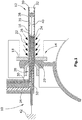
- Fig. 1 schematically shows the essential plant components of an apparatus 10 for producing a multilayer plastic / metal composite pipe 12.
- the apparatus 10 includes an extruder 14 and an extrusion unit for producing an aluminum tube 16.
- the annular nozzle of the extruder 14 is shown at 18, while the heated for the plastic deformation process metal is denoted by 20.
- the extruded aluminum tube 16 is extruded, for example, at temperatures between 450 and 500 ° C and then cools after exiting the nozzle 18 (for example, to 200 to 250 ° C, which is indicated at 22).
- a hollow mandrel 24 is inserted centrally through the annular nozzle 18 having at its one end an annular nozzle 26 through which a two-layer hollow cylindrical plastic strand 28 emerges, the outside a plastic adhesive layer 30 and inside the later base tube
- Forming inner plastic layer 32 includes, Both plastic layers are co-extruded through a coextruder 34 into the cooled metal tube 16, against its inner side 36th
- a gas for example air
- the overpressure remains in the plastic tubing string 28 maintained by a stopper 38 disposed therein, which is secured by a through the hollow mandrel 24 passed through cable 40 outside of the extrusion components of the device 10 at 42.
- the metal tube 16 produced can be squeezed off with an internal plastic strand in order to prevent the overpressure from escaping.
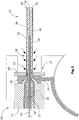
- Fig. 2 shows a slightly modified variant 10 'of an apparatus for producing a multi-layer plastic / metal composite pipe 12.
- system components identical or functionally identical to the system components according to Fig. 1 are, they are provided with the same reference numerals.
- Fig. 3 shows a device 10 "similar to the device 10 'of Fig. 2 is built on Fig. 3 However, the production of a cylindrical, strand-shaped solid or hollow profile member 44 is used in a substantially non-deformable and temperature-resistant shape. Which in the plant components and elements of the FIGS. 1 and 2 like parts are in Fig. 3 provided with the same reference numerals.
- the metal tube 16 and the plastic strand 28 are used in the device 10 "of Fig. 3 again essentially coextruded.
- an electrical conductor 46 is passed, which is embedded and wrapped after leaving the hollow mandrel 24 of the material of the plastic strand 28, so that the plastic material between the inside 36 of the metal tube 16 and the electrical conductor 46 is located.
- these devices may additionally comprise one or more extruders or a coextruder for applying single or multilayer plastic layers to the outside of the metal tube 16.
- extruders known in the production of tubes are for reasons of simplification in the FIGS. 1 to 3 not shown.
Landscapes
- Engineering & Computer Science (AREA)
- Mechanical Engineering (AREA)
- Extrusion Moulding Of Plastics Or The Like (AREA)
- Processing And Handling Of Plastics And Other Materials For Molding In General (AREA)
Description
- Die Erfindung betrifft ein Verfahren zur Herstellung eines zylindrischen, strangförmigen Teils. Insbesondere betrifft die Erfindung die Herstellung von Metall-Kunststoff-Verbundrohren, wie sie beispielsweise im Sanitär- und Heizungsbereich Verwendung finden.
- Kunststoff-Metall-Verbundrohre erfreuen sich zunehmender Beliebtheit, da sie die Vorteile der plastischen Verformbarkeit von Metallrohren mit den Vorteilen der Korrosionsbeständigkeit von Kunststoffrohren in sich vereinigen.
- Derartige Kunststoff-Metall-Verbundrohre lassen sich auf verschiedene Arten und Weisen herstellen. So ist es beispielsweise bekannt, die Metallschicht eines solchen Verbundrohres durch Formen eines Metallstreifens herzustellen, wobei die Längsränder des Metallstreifens einander überlappen und verschweißt oder verklebt sind oder aber die Längsränder des Metallstreifens auf Stoß miteinander verschweißt sind. In das so geformte Metallrohr wird dann innen ein ein- oder mehrlagiges Kunststoffrohr hineinextrudiert. Beispiele für solche Herstellungsverfahren finden sich in
DE-A-30 16 134 ,EP-A-0 353 977 ,EP-A-0 581 208 ,EP-A-0 920 972 ,WO-A-88/03084 WO-A-01/85430 - Ferner ist es bekannt, das Metallrohr auf einem bereits hergestellten ein- oder mehrschichtigen Kunststoffrohr zu formen. Ein Beispiel für ein solches Herstellungsverfahren ist in
EP-A-0 691 193 beschrieben. Weitere Beispiele finden sich inDE-A-43 10 272 ,DE-A-44 04 492 ,DE-C-195 36 689 . - Schließlich ist es auch bekannt, die Metallschicht eines Kunststoff-Metall-Verbundrohres direkt auf ein bereits hergestelltes Kunststoffrohr durch Strangpressen aufzubringen. In
EP-B-0 125 788 ist beschrieben, dass auf ein vorgefertigtes Kunststoffrohr mit radialem Abstand zu diesem ein Metallrohr extrudiert wird, das anschließend durch einen Zieh- oder dergleichen Durchmesserreduktionsprozess in seinem Durchmesser reduziert wird, um fest an dem Kunststoffrohr anzuliegen. AusUS-A-5 222 284 ist es bekannt, ein vorgefertigtes Kunststoffrohr im Durchmesser zu reduzieren, um anschließend um das Kunststoffrohr ein Metallrohr zu extrudieren (durch Strangpressen), woraufhin dann anschließend das im Durchmesser reduzierte Rohr unter Ausnutzung des Memory-Effekts sich wieder aufweitet, um dadurch dicht von innen an dem Metallrohr anzuliegen. Schließlich ist es ausDE-A-21 39 388 bekannt, ein nahtloses Metallrohr auf einen vorgefertigten Kunststoffschlauch mit Hilfe einer Metallmantelpresse aufzupressen. Problematisch hierbei sind die Temperaturen, die in der Metallmantelpresse durch die Extrusion des Metalls entstehen und auf den Kunststoffschlauch einwirken.
Aufgabe der Erfindung ist es, ein Verfahren zum Herstellen eines zylindrischen, strangförmigen Kunstoff-Metall-Verbundteils zu schaffen, das sich durch eine hohe Maßeinhaitung auszeichnet. Ein Verfahren zur Herstellung eines strangförmigen Teils, gemäß dem Oberbegriff des Anspruchs 1, ist bereits aus dem DokumentAU 2 690 971 A - ein Hohlprofil aus Metall extrudiert wird,
- das extrudierte Metallhohlprofil abkühlt und/oder abgekühlt wird und
- in das extrudierte Metallhohlprofil nach oder während dessen Abkühlung ein ein- oder mehrlagiger Kunststoffstrang hineinextrudiert wird,
- wobei der Kunststoffstrang ein in das Metallhohlprofil eingeführtes, der Wärme des extrudierten Metallhohlprofils ausgesetztes Ausgabewerkzeugs eines Extruders passiert, welches eine Ausgabeöffnung aufweist, die innerhalb eines Bereichs des Metallhohlprofils angeordnet ist, in dem dieses gegenüber seiner Temperatur bei der Extrusion abgekühlt ist.
- Das nach dem Strangpressvorgang erwärmte Metallrohr wirkt sich zusammen mit der erwärmten ein- oder mehrlagigen Kunststoffschmelze bezüglich einer innigen Haftung an dem Metallrohr positiv aus.
- Die bei der Extrusion des Metalls entstehende Wärme ist bei weitem zu groß, als dass unmittelbar nach der Extrusion der Kunststoffstrang in das Metallhohlprofil hineinextrudiert werden kann. Hierzu bedarf es vielmehr eines Ortes innerhalb des Metallhohlprofils, der in Maschinenrichtung stromab der Extrusion des Metalls angeordnet ist. Dies wird erfindungsgemäß mit Hilfe eines in das Metallhohlprofil weit hineinragenden dornförmigen Ausgabewerkzeuges realisiert. Dieses Ausgabewerkzeug, das im wesentlichen nach Art eines Rohres bzw. Dorns ausgebildet ist, transportiert die Kunststoffschmelze. Damit diese Kunststoffschmelze über den verhältnismäßig langen Weg durch das Ausgabewerkzeug seine für die Extrusion erforderliche Temperatur beibehält, müsste man dieses Ausgabewerkzeug beheizen.
- Überraschenderweise hat sich nun gezeigt, dass für die Aufheizung bzw. Temperierung des Ausgabewerkzeuges die Wärme, die von dem extrudierten Metallhohlprofil ausgeht, genutzt werden kann. Damit werden zwei Effekte erreicht, nämlich zum einen, dass sich das Metallhohlprofil durch Abgabe seiner Wärme an das Ausgabewerkzeug abkühlt, und zum anderen, dass das Ausgabewerkzeug temperiert wird, ohne andere externe Wärmequellen zu nutzen.
- Nur durch die nachträgliche Extrusion der Kunststoffschmelze von innen in das nahtlos hergestellte, extrudierte Metallhohlprofil lassen sich die unterschiedlichen Materialien Metall und Kunststoff maßhaltig miteinander verarbeiten. Dabei wird die hohe Maßhaltigkeit dadurch erzielt, dass das Metallrohr nahtlos hergestellt ist (Extrusion). Das Aufpressen bzw. Aufextrudieren des Metallrohres auf ein vorgefertigtes Kunststoffrohr, was ebenfalls zu einer hohen Maßhaltigkeit führen würde, scheidet wegen der hohen Temperaturen des extrudierten Metallhohlprofils aus. Die Extrusion des Kunststoffstrangs in das extrudierte Metallhohlprofil hinein gelingt erfindungsgemäß dadurch, dass das Ausgabewerkzeug eine beträchtliche Länge aufweist, so dass die Kunststoffschmelze erst dann mit dem Metallhohlprofil in Kontakt kommt, wenn dieses bereits auf eine für den Kunststoff verträgliche Temperatur abgekühlt ist. Hierbei macht man sich, wie bereits oben erwähnt, zu Nutze, dass die Temperierung des Ausgabewerkzeuges über dessen volle Länge durch die Wärmeabgabe des extrudierten Metallhohlprofils erfolgt.
- Mit dem erfindungsgemäßen Verfahren lassen sich insbesondere zylindrische, strangförmige Hohl- oder Vollprofilteile herstellen. Insbesondere ist das Verfahren geeignet für die Herstellung von Mehrschicht-Kunststoff-Metall-Verbundrohren.
- Bei einer Weiterbildung der Erfindung lässt sich außen auf das Metallrohr eine ein- oder mehrlagige Kunststoffschicht vorzugsweise durch Extrusion aufbringen. Die Extrusion der außenliegenden Kunststoffschicht kann direkt auf das extrudierte Metallrohr oder nach dessen Abkühlung erfolgen. Werden mehrere Kunststoffschichten extrudiert, so kann dies durch Tandemextrusion der Einzellagen oder durch eine Coextrusion erfolgen.
- Das Metallrohr besteht bei einer vorteilhaften Ausgestaltung der Erfindung vorzugsweise aus Aluminium oder einer Aluminiumlegierung. Bei den mehrlagigen Kunststoffschichten, die in das Metallrohr hineinextrudiert werden bzw. außen auf das Metallrohr aufgebracht werden können, handelt es sich vorzugsweise um thermoplastische Materialien, wobei die jeweils an das Metallrohr angrenzenden Kunststoffschichten thermoplastische Haftvermittler umfassen.
- Das erfindungsgemäße Verfahren eignet sich insbesondere zur Herstellung von im Durchmesser größeren (beispielsweise ab 40 mm) Mehrschicht-Kunststoff/Metall-Verbundrohre, bei denen das Metallrohr aufgrund seiner Wanddicke nach seiner Herstellung nur mit großem Aufwand im Durchmesser reduziert werden kann, um in Kontakt mit dem innenliegenden Kunststoffstrang zu gelangen. Auf diese Durchmesserreduktion des Metallrohrs wird daher erfindungsgemäß verzichtet, indem der Kunststoffstrang in das fertig hergestellte Metallrohr hineinextrudiert wird (und zwar an dessen Innenseite). Der Nachteil einer Durchmesserreduktion des Metallrohrs besteht auch darin, dass es aufgrund der Umformung des Metalls zu Materialverhärtungen kommt, was sich wiederum nachteilig auf die Biegbarkeit des hergestellten Metall-Kunststoff-Verbundrohres auswirkt. Insoweit hat das erfindungsgemäße Verfahren auch Vorteile bei der Herstellung im Durchmesser kleinerer (beispielsweise bis 40 mm) Mehrschicht-Kunststoff/Metall-Verbundrohre, da auf die bei diesen Rohrdimensionen maschinell beherrschbare Durchmesserreduktion des Metallrohres verzichtet werden kann. Die Herstellung im Durchmesser kleinerer Mehrschicht-Kunststoff/Metall-Verbundrohre ist erfindungsgemäß nicht zuletzt auch deshalb möglich, weil das Ausgabewerkzeug zu seiner Temperierung nicht mit separaten Heizelementen oder dergleichen, die Bestandteil des Ausgabewerkzeugs sein müssten und dieses damit im Durchmesser vergrößern würden, erwärmt werden muss, da die erforderliche Wärme zur Temperierung des Ausgabewerkzeuges durch die Wärme des extrudierten Metallhohlprofils zur Verfügung gestellt wird.
- Die Erwärmung des Ausgabewerkzeuges durch das sich abkühlende, extrudierte Metallhohlprofil wird zweckmäßigerweise durch eine thermische Kopplung zwischen beiden realisiert. Hierbei ist es besonders zweckmäßig, wenn das extrudierte Metallhohlprofil sich unter Kontakt mit dem Ausgabewerkzeug über dieses bewegt. Dabei kann das Ausgabewerkzeug die weitere Funktion der Formstabilisierung des extrudierten Metallhohlprofils innerhalb der Phase unmittelbar nach der Extrusion übernehmen. Bei dem Ausgabewerkzeug handelt es sich zweckmäßigerweise um ein Rohr oder dornförmiges Werkzeug, das einen Ringraum aufweist, an dessen Ausgabeende eine Ringdüse angeordnet ist. Der Ringraum, der durch zwei zueinander konzentrische Wände bzw. Flächen (z.B. Rohre) definiert ist, kann durch die Wände verbindende Stege oder dergleichen stabilisiert sein. Diese Stege werden von der den Ringraum passierenden Kunststoffschmelze umströmt, was für den Extrusionsprozess des Kunststoffstrangs nicht von Nachteil ist. Bei einem mehrschichtigen Kunststofifschmelzenstrom sollte der Ringraum über seine gesamte Länge frei sein. Die sich zwischen den Ringraum bildenden Rohre sind dann an ihren einen Enden gegeneinander fixiert.
Das erfindungsgemäße Verfahren eignet sich auch, wie bereits oben erwähnt, zur Herstellung von Vollprofilteilen. Beispielsweise kann das erfindungsgemäße Verfahren zur Herstellung eines von Kunststoff und Metall umgebenen Kabels oder eines anderen Voll- oder Hohlprofils in im wesentlichen nicht deformierbarer und temperaturbeständiger Form, z.B. ein Metallrohr, eingesetzt werden. Das Kabel bzw. Profil wird durch die Ringdüsen der Extruder für den Kunststoffstrang und das Metallrohr zentrisch hindurchgeführt, so dass bei der Extrusion des Kunststoffstrangs der Raum zwischen dem zentrisch angeordneten Leiter und dem Metallrohr mit Kunststoffmaterial ausgefüllt wird. Bei diesem Kunststoffmaterial kann es sich beispielsweise um ein schäumbares Kunststoffmaterial handeln. Hierbei ist ein Haftvermittler nicht zwingend erforderlich, wenn gewährleistet ist, dass der schäumbare Kunststoff selbst ausreichend stabil an der Innenseite des Metallrohres haftet. - Die Erfindung wird nachfolgend anhand der Ausführungsbeispiele und unter Bezugnahme auf die Zeichnung näher erläutert. Im einzelnen zeigen dabei:
- Fig. 1
- die Extrusions-Anlagenkomponenten für die Herstellung eines zylindrischen, strangförmigen Hohlprofilteils gemäß einem ersten Ausführungsbeispiel der Erfindung,
- Fig. 2
- die Extrusions-Anlagenkomponenten für die Herstellung eines zylindrischen, strangförmigen Hohlprofilteils gemäß einem zweiten Ausführungsbeispiel der Erfindung, und
- Fig. 3
- die Extrusions-Anlagenkomponenten für die Herstellung eines zylindrischen, strangförmigen Vollprofilteils gemäß einem ersten und zweiten Ausführungsbeispiel der Erfindung.
-
Fig. 1 zeigt schematisch die wesentlichen Anlagenkomponenten einer Vorrichtung 10 zur Herstellung eines Mehrschicht-Kunststoff/Metall-Verbundrohres 12. Zur Vorrichtung 10 gehört ein Extruder 14 bzw. eine Strangpress-Einheit zur Herstellung eines Aluminiumrohres 16. Die Ringdüse des Extruders 14 ist bei 18 dargestellt, während das für den plastischen Verformungsprozess erwärmte Metall mit 20 bezeichnet ist. Das extrudierte Aluminiumrohr 16 wird beispielsweise bei Temperaturen zwischen 450 und 500 °C extrudiert und kühlt dann nach dem Austritt aus der Düse 18 ab (beispielsweise auf 200 bis 250 °C, was bei 22 angedeutet ist). - In das extrudierte Metallrohr 16 ist durch die Ringdüse 18 hindurch ein hohler Dorn 24 zentrisch eingeführt, der an seinem einen Ende eine Ringdüse 26 aufweist, über die ein zweilagiger hohlzylindrischer Kunststoffstrang 28 austritt, der außen eine Kunststoff-Haftvermittlerschicht 30 und innen eine das spätere Basisrohr bildende Innenkunststoffschicht 32 umfasst, Beide Kunststoffschichten werden über einen Coextruder 34 gemeinsam in das abgekühlte Metallrohr 16 hineinextrudiert, und zwar gegen dessen Innenseite 36. Damit die Kunststoffschmelze dort zuverlässig verbleibt, wird durch den Dorn 24 ein Gas, z.B. Luft, in den Kunststoffschmelzeschlauch (hohlzylindrischer Kunststoffschmelzestrang 28) eingeleitet und damit ein Überdruck aufgebaut. Der Überdruck bleibt im Kunststoffrohrstrang 28 durch einen in diesem angeordneten Stopfen 38 aufrechterhalten, der über ein durch den Hohldorn 24 hindurchgeführtes Seil 40 außerhalb der Extrusionskomponenten der Vorrichtung 10 bei 42 befestigt ist. Anstelle des Stopfens 38 kann das hergestellte Metallrohr 16 mit innenliegendem Kunststoffstrang abgequetscht werden, um ein Entweichen des Überdrucks zu vermeiden.
-
Fig. 2 zeigt eine geringfügig abgewandelte Variante 10' einer Vorrichtung zur Herstellung eines Mehrschicht-Kunststoff/Metall-Verbundrohres 12. Soweit die inFig. 2 gezeigten Anlagenkomponenten identisch bzw. funktionsgleich mit den Anlagenkomponenten gemäßFig. 1 sind, sind sie mit den gleichen Bezugszeichen versehen. - Im Unterschied zur Vorrichtung 10 der
Fig. 1 werden bei der Vorrichtung 10' derFig. 2 das Metallrohr 16 und der Kunststoffstrang 28 coextrudiert. Ansonsten läuft der Herstellungsprozess so, wie oben beschrieben, ab. -
Fig. 3 zeigt eine Vorrichtung 10 ", die ähnlich zur Vorrichtung 10' derFig. 2 aufgebaut ist, beiFig. 3 jedoch der Herstellung eines zylindrischen, strangförmigen Voll- oder Hohlprofilteils 44 in im wesentlichen nicht deformierbarer und temperaturbeständiger Form dient. Die sich in den Anlagenkomponenten und Elementen derFiguren 1 und2 gleichenden Teile sind inFig. 3 mit den gleichen Bezugszeichen versehen. - Das Metallrohr 16 und der Kunststoffstrang 28 werden bei der Vorrichtung 10" der
Fig. 3 wiederum im wesentlichen coextrudiert. Durch den Hohldorn 24 des Extruders 34 für den Kunststoffstrang 28 ist ein elektrischer Leiter 46 hindurchgeführt, der nach dem Verlassen des Hohldorns 24 von dem Material des Kunststoffstrangs 28 eingebettet und umhüllt wird, so dass sich das Kunststoffmaterial zwischen der Innenseite 36 des Metallrohres 16 und dem elektrischen Leiter 46 befindet. Mit der Vorrichtung 10" derFig. 3 lassen sich also beispielsweise elektrisch isolierte Kabel herstellen, die ein metallisches Rohr aufweisen, welches den elektrischen Leiter 46 unter Zwischenschaltung eines Kunststoffmaterials beinhaltet. - Bezüglich der in den
Figuren 1 bis 3 gezeigten Vorrichtungen 10, 10' und 10" sei noch gesagt, dass diese Vorrichtungen noch zusätzlich einen oder mehrere Extruder oder einen Coextruder zum Aufbringen ein- oder mehrlagiger Kunststoffschichten außen auf das Metallrohr 16 umfassen können. Diese bei der Rohrherstellung bekannten zusätzlichen Extruder sind aus Vereinfachungsgründen in denFiguren 1 bis 3 nicht eingezeichnet.
Claims (12)
- Verfahren zur Herstellung eines strangförmigen Teils, bei dem- ein Hohlprofil (16) aus Metall extrudiert wird,- das extrudierte Metallhohlprofil (16) abkühlt und/oder abgekühlt wird und- in das extrudierte Metallhohlprofil (16) nach oder während dessen Abkühlung ein ein- oder mehrlagiger Kunststoffstrang (28) hineinextrudiert wird,- wobei der Kunststoffstrang (28) ein in das Metallhohlprofil (16) eingeführtes, der Wärme des extrudierten Metallhohlprofils (16) ausgesetztes Ausgabewerkzeugs (24) eines Extruders (34) passiert, welches eine Ausgabeöffnung (26) aufweist, die innerhalb eines Bereichs des Metallhohlprofils (16) angeordnet ist, in dem dieses gegenüber seiner Temperatur bei der Extrusion abgekühlt ist, dadurch gekennzeichnet, dass- das Ausgabewerkzeug (24) thermisch mit dem Metallhohlprofil (16) gekoppelt ist und durch dieses temperiert wird durch dass das Ausgabewerkzeug (24) die Innenseiten des Metallhohlprofils (16) kontaktiert.
- Verfahren nach Anspruch 1, dadurch gekennzeichnet, dass außen auf das Metallhohlprofil (16) eine ein- oder mehrlagige Kunststoffschicht vorzugsweise durch Extrusion, Tandemextrusionen oder Coextrusion aufgebracht wird.
- Verfahren nach einem der Ansprüche 1 bis 2, dadurch gekennzeichnet, dass der in das Metallhohlprofil (16) hineinextrudierte ein- oder mehrlagige Kunststoffstrang (28) als Kunststoffrohr ausgebildet wird und dass innerhalb des Kunststoffrohres zum Andrücken des Kunststoffrohres gegen das Metallrohr (16) ein Überdruck erzeugt wird.
- Verfahren nach einem der Ansprüche 1 bis 2, dadurch gekennzeichnet, dass der ein- oder mehrlagige Kunststoffstrang (28) als Vollprofil ausgebildet wird und dass in das Vollprofil während dessen Extrusion ein Voll- oder Hohlprofilteil in im wesentlichen nicht deformierbarer und temperaturbeständiger Form, insbesondere ein ein- oder mehradriger elektrischer Leiter (46) eingebracht wird.
- Verfahren nach einem der Ansprüche 1 bis 4, dadurch gekennzeichnet, dass das Metallhohlprofil (16) ein unterhalb seines Schmelzpunktes plastisch verformbares und extrudierbares Metall oder eine unterhalb ihres Schmelzpunktes plastisch verformbare und extrudierbare Metalllegierung aufweist.
- Verfahren nach Anspruch 5, dadurch gekennzeichnet, dass das Metall Aluminum oder die Metalllegierung eine Aluminiumlegierung aufweist.
- Verfahren nach einem der Ansprüche 1 bis 6, dadurch gekennzeichnet, dass der Kunststoffstrang (28) eine Außenlage (30) aus einem Haftvermittler und eine an die Außenlage (30) angrenzende Polymermateriallage aufweist.
- Verfahren nach Anspruch 2 oder einem der vorhergehenden Ansprüche, soweit auf Anspruch 3 rückbezogen, dadurch gekennzeichnet, dass die außen auf das Metallhohlprofil (16) aufgebrachte Kunststoffschicht eine an das Metallhohlprofil (16) angrenzende Innenlage aus Haftvermittler und eine an diese Innenlage angrenzende Außenlage aus Polymermaterial aufweist.
- Verfahren nach einem der Ansprüche 1 bis 8, dadurch gekennzeichnet, dass das Metallrohr und der Kunststoffstrang (28) coextrudiert oder durch aufeinanderfolgend angeordnete Extruder erzeugt werden.
- Verfahren nach einem der Ansprüche 1 bis 9, dadurch gekennzeichnet, dass das Metallhohlprofil (16) ein Metallrohr ist.
- Verfahren nach einem der Ansprüche 1 bis 10, dadurch gekennzeichnet, dass der Kunststoffstrang (28) ein insbesondere aufschäumbares Kunststoffmaterial aufweist, das haftende oder nicht haftende Eigenschaften zum Metall aufweist.
- Verfahren nach einem der Ansprüche 1 bis 11, dadurch gekennzeichnet, dass das Ausgabewerkzeug (24) einen Dorn mit einem Ringraum aufweist, an dessen axialem Ende sich eine Ringdüse als Ausgabeöffnung (26) des Doms befindet.
Priority Applications (4)
| Application Number | Priority Date | Filing Date | Title |
|---|---|---|---|
| PL07803104T PL2061638T3 (pl) | 2006-09-02 | 2007-08-31 | Sposób wytwarzania cylindrycznej części pasmowej |
| EP17196268.1A EP3287253B1 (de) | 2006-09-02 | 2007-08-31 | Verfahren zur herstellung eines zylindrischen, strangförmigen teils |
| SI200732000T SI2061638T1 (en) | 2006-09-02 | 2007-08-31 | A process for making a cylindrical, stranded part |
| EP07803104.4A EP2061638B1 (de) | 2006-09-02 | 2007-08-31 | Verfahren zur herstellung eines zylindrischen, strangförmigen teils |
Applications Claiming Priority (3)
| Application Number | Priority Date | Filing Date | Title |
|---|---|---|---|
| EP06018394 | 2006-09-02 | ||
| PCT/EP2007/059099 WO2008028866A1 (de) | 2006-09-02 | 2007-08-31 | Verfahren zur herstellung eines zylindrischen, strangförmigen teils |
| EP07803104.4A EP2061638B1 (de) | 2006-09-02 | 2007-08-31 | Verfahren zur herstellung eines zylindrischen, strangförmigen teils |
Related Child Applications (2)
| Application Number | Title | Priority Date | Filing Date |
|---|---|---|---|
| EP17196268.1A Division EP3287253B1 (de) | 2006-09-02 | 2007-08-31 | Verfahren zur herstellung eines zylindrischen, strangförmigen teils |
| EP17196268.1A Division-Into EP3287253B1 (de) | 2006-09-02 | 2007-08-31 | Verfahren zur herstellung eines zylindrischen, strangförmigen teils |
Publications (2)
| Publication Number | Publication Date |
|---|---|
| EP2061638A1 EP2061638A1 (de) | 2009-05-27 |
| EP2061638B1 true EP2061638B1 (de) | 2017-11-22 |
Family
ID=37744371
Family Applications (2)
| Application Number | Title | Priority Date | Filing Date |
|---|---|---|---|
| EP07803104.4A Active EP2061638B1 (de) | 2006-09-02 | 2007-08-31 | Verfahren zur herstellung eines zylindrischen, strangförmigen teils |
| EP17196268.1A Active EP3287253B1 (de) | 2006-09-02 | 2007-08-31 | Verfahren zur herstellung eines zylindrischen, strangförmigen teils |
Family Applications After (1)
| Application Number | Title | Priority Date | Filing Date |
|---|---|---|---|
| EP17196268.1A Active EP3287253B1 (de) | 2006-09-02 | 2007-08-31 | Verfahren zur herstellung eines zylindrischen, strangförmigen teils |
Country Status (14)
| Country | Link |
|---|---|
| US (1) | US8491744B2 (de) |
| EP (2) | EP2061638B1 (de) |
| KR (1) | KR101392951B1 (de) |
| CN (1) | CN101522391B (de) |
| AU (1) | AU2007293923B2 (de) |
| CA (1) | CA2663326C (de) |
| DK (1) | DK2061638T3 (de) |
| EA (1) | EA015142B1 (de) |
| ES (2) | ES2657634T3 (de) |
| HU (1) | HUE035550T2 (de) |
| LT (1) | LT2061638T (de) |
| PL (1) | PL2061638T3 (de) |
| SI (1) | SI2061638T1 (de) |
| WO (1) | WO2008028866A1 (de) |
Families Citing this family (4)
| Publication number | Priority date | Publication date | Assignee | Title |
|---|---|---|---|---|
| EP2139624B1 (de) | 2007-04-20 | 2017-03-01 | Halcor Metal Works S.A. | Verfahren und vorrichtung zur herstellung von nahtlosen mehrschichtigen verbundrohren |
| CN103212601B (zh) * | 2013-04-08 | 2016-02-03 | 无锡市百宏传动电器有限公司 | 一种滑触线复合导电轨道的单缸挤出设备及生产方法 |
| US11229934B2 (en) * | 2019-01-17 | 2022-01-25 | Ford Global Technologies, Llc | Methods of forming fiber-reinforced composite parts and fiber-reinforced composite parts formed thereby |
| WO2025168740A1 (en) | 2024-02-07 | 2025-08-14 | Uponor Innovation Ab | Polymeric pipe |
Citations (1)
| Publication number | Priority date | Publication date | Assignee | Title |
|---|---|---|---|---|
| AU2690971A (en) * | 1970-03-24 | 1972-09-28 | Industrie Pirelli Societa Per Azioni | Method of and apparatus for forming a metal tub having a lining overs it inner surfaces, for example a waveguide |
Family Cites Families (19)
| Publication number | Priority date | Publication date | Assignee | Title |
|---|---|---|---|---|
| US4093693A (en) * | 1969-08-11 | 1978-06-06 | Lemelson Jerome H | Method for making composite articles |
| DE2139388A1 (de) * | 1971-08-06 | 1973-02-22 | Felten & Guilleaume Kabelwerk | Verfahren zum herstellen eines nahtlosen metallrohres |
| US4304713A (en) * | 1980-02-29 | 1981-12-08 | Andrew Corporation | Process for preparing a foamed perfluorocarbon dielectric coaxial cable |
| DE3016134A1 (de) | 1980-04-24 | 1981-10-29 | Mecano-Bundy Gmbh, 6900 Heidelberg | Mehrlagenrohr |
| US4370186A (en) * | 1980-12-19 | 1983-01-25 | Nadia Nicoll, Societe A Responsabilite Limitee | Method for manufacturing a metal-plastics composite tube and apparatus for carrying out said method |
| GB8513158D0 (en) | 1985-05-24 | 1985-06-26 | Babcock Wire Equipment | Continuous extrusion apparatus |
| GB8625432D0 (en) * | 1986-10-23 | 1986-11-26 | Super Pipe Int Corp | Forming plastics coated tube |
| GB2223427B (en) | 1988-08-03 | 1992-09-30 | Kitechnology Bv | Apparatus for forming plastics coated tube |
| GB9100317D0 (en) * | 1991-01-08 | 1991-02-20 | Holton Machinery Ltd | Co-axial cable |
| DE4225011B4 (de) | 1992-07-29 | 2005-12-15 | Uponor Innovation Ab | Vorrichtung zum Herstellen eines Metall-Kunststoff-Verbundrohres |
| GB2274795B (en) * | 1993-02-06 | 1997-01-22 | Keith John Kingham | Method and apparatus for producing non-ferrous metal clad 2,3 and 4-part composite products |
| DE4310272A1 (de) | 1993-03-30 | 1994-10-06 | Emil Heinrich Friedrich | Verfahren zur Herstellung von mehrschichtigen Verbundrohren mit Metalleinlagen |
| GB9319408D0 (en) | 1993-09-20 | 1993-11-03 | Avondale Property Holdings Ltd | Extrusion of laminate pipes |
| DE4404492C2 (de) | 1993-12-06 | 2003-04-24 | Becker Plastics Gmbh | Verfahren zur Herstellung eines Mehrschichtverbundrohres |
| ATE175621T1 (de) | 1994-07-05 | 1999-01-15 | Hewing Gmbh | Verfahren zum kontinuierlichen herstellen eines ein metallrohr und ein kunststoff-innenrohr aufweisenden verbundrohres |
| DE19536689A1 (de) | 1994-10-12 | 1996-04-18 | Lucjan Kolek | Leuchtmittelhalter |
| JPH11309510A (ja) | 1998-04-28 | 1999-11-09 | Hitachi Cable Ltd | 内面被覆金属管の製造方法 |
| DE10022823A1 (de) | 2000-05-10 | 2001-11-22 | Unicor Extrusionstechnik Gmbh | Verfahren zur Herstellung von Mehrschicht-Metall-Verbundrohren |
| CN1342549A (zh) | 2001-09-26 | 2002-04-03 | 周锡明 | 无缝铝塑复合管的制造方法 |
-
2007
- 2007-08-31 AU AU2007293923A patent/AU2007293923B2/en active Active
- 2007-08-31 DK DK07803104.4T patent/DK2061638T3/en active
- 2007-08-31 EP EP07803104.4A patent/EP2061638B1/de active Active
- 2007-08-31 EA EA200970243A patent/EA015142B1/ru not_active IP Right Cessation
- 2007-08-31 CN CN2007800378193A patent/CN101522391B/zh active Active
- 2007-08-31 ES ES07803104.4T patent/ES2657634T3/es active Active
- 2007-08-31 SI SI200732000T patent/SI2061638T1/en unknown
- 2007-08-31 KR KR1020097006669A patent/KR101392951B1/ko not_active Expired - Fee Related
- 2007-08-31 ES ES17196268T patent/ES3046197T3/es active Active
- 2007-08-31 US US12/439,577 patent/US8491744B2/en active Active
- 2007-08-31 PL PL07803104T patent/PL2061638T3/pl unknown
- 2007-08-31 LT LTEP07803104.4T patent/LT2061638T/lt unknown
- 2007-08-31 HU HUE07803104A patent/HUE035550T2/en unknown
- 2007-08-31 EP EP17196268.1A patent/EP3287253B1/de active Active
- 2007-08-31 WO PCT/EP2007/059099 patent/WO2008028866A1/de not_active Ceased
- 2007-08-31 CA CA2663326A patent/CA2663326C/en active Active
Patent Citations (1)
| Publication number | Priority date | Publication date | Assignee | Title |
|---|---|---|---|---|
| AU2690971A (en) * | 1970-03-24 | 1972-09-28 | Industrie Pirelli Societa Per Azioni | Method of and apparatus for forming a metal tub having a lining overs it inner surfaces, for example a waveguide |
Also Published As
| Publication number | Publication date |
|---|---|
| AU2007293923B2 (en) | 2011-12-08 |
| EP2061638A1 (de) | 2009-05-27 |
| ES2657634T3 (es) | 2018-03-06 |
| HUE035550T2 (en) | 2018-05-28 |
| KR20090050095A (ko) | 2009-05-19 |
| DK2061638T3 (en) | 2018-02-05 |
| EP3287253A1 (de) | 2018-02-28 |
| US8491744B2 (en) | 2013-07-23 |
| KR101392951B1 (ko) | 2014-05-09 |
| WO2008028866A1 (de) | 2008-03-13 |
| US20100065196A1 (en) | 2010-03-18 |
| CA2663326C (en) | 2014-12-30 |
| AU2007293923A1 (en) | 2008-03-13 |
| SI2061638T1 (en) | 2018-04-30 |
| CA2663326A1 (en) | 2008-03-13 |
| LT2061638T (lt) | 2018-04-10 |
| EP3287253C0 (de) | 2025-07-23 |
| EP3287253B1 (de) | 2025-07-23 |
| EA200970243A1 (ru) | 2009-08-28 |
| CN101522391A (zh) | 2009-09-02 |
| PL2061638T3 (pl) | 2018-04-30 |
| CN101522391B (zh) | 2011-11-23 |
| EA015142B1 (ru) | 2011-06-30 |
| ES3046197T3 (en) | 2025-12-01 |
Similar Documents
| Publication | Publication Date | Title |
|---|---|---|
| DE3690231C2 (de) | Verfahren zum Herstellen eines Wärmeisolierrohrs | |
| EP0726134A1 (de) | Verfahren und Anlage zur Herstellung eines Mehrschicht-Rohres aus thermoplastischem Kunststoff, insbesondere Polyolefin | |
| EP3112124B1 (de) | Verfahren zur beschichtung einer rohrleitung | |
| EP3758910B1 (de) | Verfahren und vorrichtung zur herstellung eines wärmegedämmten leitungsrohrs | |
| DE3114185A1 (de) | Verfahren zur herstellung einer laminierten umhuellung und das dabei erhaltene produkt | |
| EP3287253B1 (de) | Verfahren zur herstellung eines zylindrischen, strangförmigen teils | |
| DE1778471C3 (de) | Verfahren und Vorrichtung zum Herstellen eines Verbundkörpers durch Coextrudieren | |
| DE4323026C2 (de) | Verfahren zur Herstellung eines versteiften Schlauches sowie Vorrichtung zur Durchführung des Verfahrens | |
| EP0531790A2 (de) | Verbundrohr, Verfahren zu seiner Herstellung und Rohrleitungsverbindung aus dem Verbundrohr | |
| DE4323838B4 (de) | Verfahren zur Herstellung eines mehrschichtigen Leitungsrohres | |
| DE112008001067B4 (de) | Verfahren zur Herstellung eines metallverstärkten Kunststoff-Verbundrohrs und metallverstärktes Kunststoff-Verbundrohr | |
| DE2809266C3 (de) | Vorrichtung zur Herstellung einer Koaxialkabelseele | |
| DE3023214C2 (de) | Verfahren zur Herstellung eines Verbundrohres | |
| DE102020106777A1 (de) | Thermoplastischer Schlauch sowie eine Vorrichtung und ein Verfahren zur Herstellung eines solchen | |
| DE102012112280B4 (de) | Verfahren zum Herstellen eines Isolierverbundrohrs | |
| EP3297805A1 (de) | Verfahren sowie vorrichtung zur herstellung eines strangguts sowie stranggut | |
| DE10146406C1 (de) | Mehrschicht-Verbundrohr mit Ausweichzone | |
| DE69706136T2 (de) | Kunststoffrohr mit mehreren lumen | |
| EP1361038B1 (de) | Verfahren und Vorrichtung zur Herstellung eines Verbundrohres | |
| DE19925097A1 (de) | Verbundrohr mit PVDC-Innenschicht | |
| EP1782937A2 (de) | Verfahren zur Umhüllung eines Hohlprofils mit Metallfolie | |
| EP1287973A1 (de) | Anordnung sowie Verfahren zum Tiefziehen von Kunststoff-Metall-Kunststoff-Mehrschichtrohren | |
| EP1876006B1 (de) | Vorrichtung zur Herstellung von Metallverbundrohren | |
| EP0691193A1 (de) | Verfahren zum kontinuierlichen Herstellen eines ein Metallrohr und ein Kunststoff-Innenrohr aufweisenden Verbundrohres | |
| DE20214563U1 (de) | Hydraulikleitung sowie stranggepresstes Verbundprofil zur Verwendung in einer solchen Hydraulikleitung |
Legal Events
| Date | Code | Title | Description |
|---|---|---|---|
| PUAI | Public reference made under article 153(3) epc to a published international application that has entered the european phase |
Free format text: ORIGINAL CODE: 0009012 |
|
| 17P | Request for examination filed |
Effective date: 20090402 |
|
| AK | Designated contracting states |
Kind code of ref document: A1 Designated state(s): AT BE BG CH CY CZ DE DK EE ES FI FR GB GR HU IE IS IT LI LT LU LV MC MT NL PL PT RO SE SI SK TR |
|
| AX | Request for extension of the european patent |
Extension state: AL BA HR MK RS |
|
| TPAC | Observations filed by third parties |
Free format text: ORIGINAL CODE: EPIDOSNTIPA |
|
| DAX | Request for extension of the european patent (deleted) | ||
| RAP1 | Party data changed (applicant data changed or rights of an application transferred) |
Owner name: UPONOR INNOVATION AB |
|
| STAA | Information on the status of an ep patent application or granted ep patent |
Free format text: STATUS: EXAMINATION IS IN PROGRESS |
|
| 17Q | First examination report despatched |
Effective date: 20161027 |
|
| REG | Reference to a national code |
Ref country code: DE Ref legal event code: R079 Ref document number: 502007015960 Country of ref document: DE Free format text: PREVIOUS MAIN CLASS: B29C0047020000 Ipc: B29C0047060000 |
|
| RIC1 | Information provided on ipc code assigned before grant |
Ipc: B21C 23/24 20060101ALI20170323BHEP Ipc: B29C 47/06 20060101AFI20170323BHEP Ipc: B29C 47/02 20060101ALI20170323BHEP |
|
| GRAP | Despatch of communication of intention to grant a patent |
Free format text: ORIGINAL CODE: EPIDOSNIGR1 |
|
| STAA | Information on the status of an ep patent application or granted ep patent |
Free format text: STATUS: GRANT OF PATENT IS INTENDED |
|
| INTG | Intention to grant announced |
Effective date: 20170613 |
|
| GRAS | Grant fee paid |
Free format text: ORIGINAL CODE: EPIDOSNIGR3 |
|
| GRAA | (expected) grant |
Free format text: ORIGINAL CODE: 0009210 |
|
| STAA | Information on the status of an ep patent application or granted ep patent |
Free format text: STATUS: THE PATENT HAS BEEN GRANTED |
|
| AK | Designated contracting states |
Kind code of ref document: B1 Designated state(s): AT BE BG CH CY CZ DE DK EE ES FI FR GB GR HU IE IS IT LI LT LU LV MC MT NL PL PT RO SE SI SK TR |
|
| REG | Reference to a national code |
Ref country code: GB Ref legal event code: FG4D Free format text: NOT ENGLISH |
|
| REG | Reference to a national code |
Ref country code: CH Ref legal event code: EP |
|
| REG | Reference to a national code |
Ref country code: IE Ref legal event code: FG4D Free format text: LANGUAGE OF EP DOCUMENT: GERMAN |
|
| REG | Reference to a national code |
Ref country code: AT Ref legal event code: REF Ref document number: 947995 Country of ref document: AT Kind code of ref document: T Effective date: 20171215 |
|
| REG | Reference to a national code |
Ref country code: DE Ref legal event code: R096 Ref document number: 502007015960 Country of ref document: DE |
|
| REG | Reference to a national code |
Ref country code: RO Ref legal event code: EPE |
|
| REG | Reference to a national code |
Ref country code: DK Ref legal event code: T3 Effective date: 20180201 |
|
| REG | Reference to a national code |
Ref country code: NL Ref legal event code: FP |
|
| REG | Reference to a national code |
Ref country code: SE Ref legal event code: TRGR |
|
| REG | Reference to a national code |
Ref country code: ES Ref legal event code: FG2A Ref document number: 2657634 Country of ref document: ES Kind code of ref document: T3 Effective date: 20180306 |
|
| REG | Reference to a national code |
Ref country code: HU Ref legal event code: AG4A Ref document number: E035550 Country of ref document: HU |
|
| PG25 | Lapsed in a contracting state [announced via postgrant information from national office to epo] |
Ref country code: GR Free format text: LAPSE BECAUSE OF FAILURE TO SUBMIT A TRANSLATION OF THE DESCRIPTION OR TO PAY THE FEE WITHIN THE PRESCRIBED TIME-LIMIT Effective date: 20180223 |
|
| REG | Reference to a national code |
Ref country code: SK Ref legal event code: T3 Ref document number: E 26518 Country of ref document: SK |
|
| PG25 | Lapsed in a contracting state [announced via postgrant information from national office to epo] |
Ref country code: EE Free format text: LAPSE BECAUSE OF FAILURE TO SUBMIT A TRANSLATION OF THE DESCRIPTION OR TO PAY THE FEE WITHIN THE PRESCRIBED TIME-LIMIT Effective date: 20171122 Ref country code: CY Free format text: LAPSE BECAUSE OF FAILURE TO SUBMIT A TRANSLATION OF THE DESCRIPTION OR TO PAY THE FEE WITHIN THE PRESCRIBED TIME-LIMIT Effective date: 20171122 |
|
| REG | Reference to a national code |
Ref country code: DE Ref legal event code: R097 Ref document number: 502007015960 Country of ref document: DE |
|
| REG | Reference to a national code |
Ref country code: FR Ref legal event code: PLFP Year of fee payment: 12 |
|
| PG25 | Lapsed in a contracting state [announced via postgrant information from national office to epo] |
Ref country code: MT Free format text: LAPSE BECAUSE OF FAILURE TO SUBMIT A TRANSLATION OF THE DESCRIPTION OR TO PAY THE FEE WITHIN THE PRESCRIBED TIME-LIMIT Effective date: 20171122 |
|
| PLBE | No opposition filed within time limit |
Free format text: ORIGINAL CODE: 0009261 |
|
| STAA | Information on the status of an ep patent application or granted ep patent |
Free format text: STATUS: NO OPPOSITION FILED WITHIN TIME LIMIT |
|
| 26N | No opposition filed |
Effective date: 20180823 |
|
| REG | Reference to a national code |
Ref country code: DE Ref legal event code: R079 Ref document number: 502007015960 Country of ref document: DE Free format text: PREVIOUS MAIN CLASS: B29C0047060000 Ipc: B29C0048180000 |
|
| PG25 | Lapsed in a contracting state [announced via postgrant information from national office to epo] |
Ref country code: MC Free format text: LAPSE BECAUSE OF FAILURE TO SUBMIT A TRANSLATION OF THE DESCRIPTION OR TO PAY THE FEE WITHIN THE PRESCRIBED TIME-LIMIT Effective date: 20171122 |
|
| PG25 | Lapsed in a contracting state [announced via postgrant information from national office to epo] |
Ref country code: LU Free format text: LAPSE BECAUSE OF NON-PAYMENT OF DUE FEES Effective date: 20180831 |
|
| PG25 | Lapsed in a contracting state [announced via postgrant information from national office to epo] |
Ref country code: PT Free format text: LAPSE BECAUSE OF FAILURE TO SUBMIT A TRANSLATION OF THE DESCRIPTION OR TO PAY THE FEE WITHIN THE PRESCRIBED TIME-LIMIT Effective date: 20171122 |
|
| PG25 | Lapsed in a contracting state [announced via postgrant information from national office to epo] |
Ref country code: IS Free format text: LAPSE BECAUSE OF FAILURE TO SUBMIT A TRANSLATION OF THE DESCRIPTION OR TO PAY THE FEE WITHIN THE PRESCRIBED TIME-LIMIT Effective date: 20180322 |
|
| P01 | Opt-out of the competence of the unified patent court (upc) registered |
Effective date: 20230602 |
|
| PGFP | Annual fee paid to national office [announced via postgrant information from national office to epo] |
Ref country code: NL Payment date: 20250821 Year of fee payment: 19 |
|
| PGFP | Annual fee paid to national office [announced via postgrant information from national office to epo] |
Ref country code: HU Payment date: 20250825 Year of fee payment: 19 |
|
| PGFP | Annual fee paid to national office [announced via postgrant information from national office to epo] |
Ref country code: FI Payment date: 20250822 Year of fee payment: 19 Ref country code: ES Payment date: 20250925 Year of fee payment: 19 |
|
| PGFP | Annual fee paid to national office [announced via postgrant information from national office to epo] |
Ref country code: LT Payment date: 20250723 Year of fee payment: 19 Ref country code: DK Payment date: 20250825 Year of fee payment: 19 Ref country code: DE Payment date: 20250820 Year of fee payment: 19 |
|
| PGFP | Annual fee paid to national office [announced via postgrant information from national office to epo] |
Ref country code: PL Payment date: 20250821 Year of fee payment: 19 Ref country code: TR Payment date: 20250825 Year of fee payment: 19 Ref country code: IT Payment date: 20250820 Year of fee payment: 19 |
|
| PGFP | Annual fee paid to national office [announced via postgrant information from national office to epo] |
Ref country code: BE Payment date: 20250820 Year of fee payment: 19 Ref country code: BG Payment date: 20250822 Year of fee payment: 19 Ref country code: GB Payment date: 20250820 Year of fee payment: 19 |
|
| PGFP | Annual fee paid to national office [announced via postgrant information from national office to epo] |
Ref country code: FR Payment date: 20250829 Year of fee payment: 19 Ref country code: AT Payment date: 20250821 Year of fee payment: 19 |
|
| PGFP | Annual fee paid to national office [announced via postgrant information from national office to epo] |
Ref country code: SE Payment date: 20250820 Year of fee payment: 19 Ref country code: CH Payment date: 20250901 Year of fee payment: 19 |
|
| PGFP | Annual fee paid to national office [announced via postgrant information from national office to epo] |
Ref country code: CZ Payment date: 20250827 Year of fee payment: 19 Ref country code: IE Payment date: 20250820 Year of fee payment: 19 |
|
| PGFP | Annual fee paid to national office [announced via postgrant information from national office to epo] |
Ref country code: RO Payment date: 20250825 Year of fee payment: 19 |
|
| PGFP | Annual fee paid to national office [announced via postgrant information from national office to epo] |
Ref country code: SK Payment date: 20250828 Year of fee payment: 19 |
|
| PGFP | Annual fee paid to national office [announced via postgrant information from national office to epo] |
Ref country code: LV Payment date: 20250818 Year of fee payment: 19 |
|
| PGFP | Annual fee paid to national office [announced via postgrant information from national office to epo] |
Ref country code: SI Payment date: 20250821 Year of fee payment: 19 |