EP0531790A2 - Verbundrohr, Verfahren zu seiner Herstellung und Rohrleitungsverbindung aus dem Verbundrohr - Google Patents
Verbundrohr, Verfahren zu seiner Herstellung und Rohrleitungsverbindung aus dem Verbundrohr Download PDFInfo
- Publication number
- EP0531790A2 EP0531790A2 EP92114451A EP92114451A EP0531790A2 EP 0531790 A2 EP0531790 A2 EP 0531790A2 EP 92114451 A EP92114451 A EP 92114451A EP 92114451 A EP92114451 A EP 92114451A EP 0531790 A2 EP0531790 A2 EP 0531790A2
- Authority
- EP
- European Patent Office
- Prior art keywords
- pipe
- tube
- outer tube
- inner tube
- thermoelastic
- Prior art date
- Legal status (The legal status is an assumption and is not a legal conclusion. Google has not performed a legal analysis and makes no representation as to the accuracy of the status listed.)
- Granted
Links
- 239000002131 composite material Substances 0.000 title claims abstract description 50
- 238000000034 method Methods 0.000 title claims description 18
- 238000004519 manufacturing process Methods 0.000 title claims description 7
- 229910052751 metal Inorganic materials 0.000 claims abstract description 32
- 239000002184 metal Substances 0.000 claims abstract description 32
- 229920000098 polyolefin Polymers 0.000 claims abstract description 16
- 238000005260 corrosion Methods 0.000 claims abstract description 10
- 230000007797 corrosion Effects 0.000 claims abstract description 10
- 238000007789 sealing Methods 0.000 claims abstract description 10
- 229920003023 plastic Polymers 0.000 claims description 31
- 239000004033 plastic Substances 0.000 claims description 31
- 238000002844 melting Methods 0.000 claims description 17
- 230000008018 melting Effects 0.000 claims description 17
- 238000010438 heat treatment Methods 0.000 claims description 15
- 239000010935 stainless steel Substances 0.000 claims description 9
- 229910001220 stainless steel Inorganic materials 0.000 claims description 9
- 150000002739 metals Chemical class 0.000 claims description 8
- 239000011324 bead Substances 0.000 claims description 7
- 239000002318 adhesion promoter Substances 0.000 claims description 4
- 239000012530 fluid Substances 0.000 claims description 4
- 238000001816 cooling Methods 0.000 claims description 3
- 238000001125 extrusion Methods 0.000 claims description 2
- 239000000853 adhesive Substances 0.000 claims 1
- 230000001070 adhesive effect Effects 0.000 claims 1
- 230000005855 radiation Effects 0.000 claims 1
- 229920000642 polymer Polymers 0.000 abstract 1
- 239000000463 material Substances 0.000 description 8
- 229920003020 cross-linked polyethylene Polymers 0.000 description 4
- 239000004703 cross-linked polyethylene Substances 0.000 description 4
- 239000000126 substance Substances 0.000 description 4
- 239000004698 Polyethylene Substances 0.000 description 3
- -1 polyethylene Polymers 0.000 description 3
- 229920000573 polyethylene Polymers 0.000 description 3
- 210000002435 tendon Anatomy 0.000 description 3
- XLYOFNOQVPJJNP-UHFFFAOYSA-N water Substances O XLYOFNOQVPJJNP-UHFFFAOYSA-N 0.000 description 3
- QVGXLLKOCUKJST-UHFFFAOYSA-N atomic oxygen Chemical compound [O] QVGXLLKOCUKJST-UHFFFAOYSA-N 0.000 description 2
- 238000009792 diffusion process Methods 0.000 description 2
- 230000000694 effects Effects 0.000 description 2
- 238000000465 moulding Methods 0.000 description 2
- 229910052760 oxygen Inorganic materials 0.000 description 2
- 239000001301 oxygen Substances 0.000 description 2
- 238000011084 recovery Methods 0.000 description 2
- 229910000831 Steel Inorganic materials 0.000 description 1
- 230000002378 acidificating effect Effects 0.000 description 1
- 150000001722 carbon compounds Chemical class 0.000 description 1
- 239000003795 chemical substances by application Substances 0.000 description 1
- 238000005520 cutting process Methods 0.000 description 1
- 238000011161 development Methods 0.000 description 1
- 230000018109 developmental process Effects 0.000 description 1
- 239000003651 drinking water Substances 0.000 description 1
- 235000020188 drinking water Nutrition 0.000 description 1
- 239000007789 gas Substances 0.000 description 1
- 230000020169 heat generation Effects 0.000 description 1
- 230000006698 induction Effects 0.000 description 1
- 229910001092 metal group alloy Inorganic materials 0.000 description 1
- 230000035515 penetration Effects 0.000 description 1
- 238000003825 pressing Methods 0.000 description 1
- 238000003672 processing method Methods 0.000 description 1
- 239000010959 steel Substances 0.000 description 1
Images


Classifications
-
- F—MECHANICAL ENGINEERING; LIGHTING; HEATING; WEAPONS; BLASTING
- F16—ENGINEERING ELEMENTS AND UNITS; GENERAL MEASURES FOR PRODUCING AND MAINTAINING EFFECTIVE FUNCTIONING OF MACHINES OR INSTALLATIONS; THERMAL INSULATION IN GENERAL
- F16L—PIPES; JOINTS OR FITTINGS FOR PIPES; SUPPORTS FOR PIPES, CABLES OR PROTECTIVE TUBING; MEANS FOR THERMAL INSULATION IN GENERAL
- F16L13/00—Non-disconnectible pipe-joints, e.g. soldered, adhesive or caulked joints
- F16L13/14—Non-disconnectible pipe-joints, e.g. soldered, adhesive or caulked joints made by plastically deforming the material of the pipe, e.g. by flanging, rolling
- F16L13/147—Non-disconnectible pipe-joints, e.g. soldered, adhesive or caulked joints made by plastically deforming the material of the pipe, e.g. by flanging, rolling by radially expanding the inner part
-
- B—PERFORMING OPERATIONS; TRANSPORTING
- B29—WORKING OF PLASTICS; WORKING OF SUBSTANCES IN A PLASTIC STATE IN GENERAL
- B29C—SHAPING OR JOINING OF PLASTICS; SHAPING OF MATERIAL IN A PLASTIC STATE, NOT OTHERWISE PROVIDED FOR; AFTER-TREATMENT OF THE SHAPED PRODUCTS, e.g. REPAIRING
- B29C63/00—Lining or sheathing, i.e. applying preformed layers or sheathings of plastics; Apparatus therefor
- B29C63/38—Lining or sheathing, i.e. applying preformed layers or sheathings of plastics; Apparatus therefor by liberation of internal stresses
- B29C63/46—Lining or sheathing, i.e. applying preformed layers or sheathings of plastics; Apparatus therefor by liberation of internal stresses of internal surfaces
-
- F—MECHANICAL ENGINEERING; LIGHTING; HEATING; WEAPONS; BLASTING
- F16—ENGINEERING ELEMENTS AND UNITS; GENERAL MEASURES FOR PRODUCING AND MAINTAINING EFFECTIVE FUNCTIONING OF MACHINES OR INSTALLATIONS; THERMAL INSULATION IN GENERAL
- F16L—PIPES; JOINTS OR FITTINGS FOR PIPES; SUPPORTS FOR PIPES, CABLES OR PROTECTIVE TUBING; MEANS FOR THERMAL INSULATION IN GENERAL
- F16L13/00—Non-disconnectible pipe-joints, e.g. soldered, adhesive or caulked joints
- F16L13/14—Non-disconnectible pipe-joints, e.g. soldered, adhesive or caulked joints made by plastically deforming the material of the pipe, e.g. by flanging, rolling
- F16L13/141—Non-disconnectible pipe-joints, e.g. soldered, adhesive or caulked joints made by plastically deforming the material of the pipe, e.g. by flanging, rolling by crimping or rolling from the outside
-
- F—MECHANICAL ENGINEERING; LIGHTING; HEATING; WEAPONS; BLASTING
- F16—ENGINEERING ELEMENTS AND UNITS; GENERAL MEASURES FOR PRODUCING AND MAINTAINING EFFECTIVE FUNCTIONING OF MACHINES OR INSTALLATIONS; THERMAL INSULATION IN GENERAL
- F16L—PIPES; JOINTS OR FITTINGS FOR PIPES; SUPPORTS FOR PIPES, CABLES OR PROTECTIVE TUBING; MEANS FOR THERMAL INSULATION IN GENERAL
- F16L37/00—Couplings of the quick-acting type
- F16L37/02—Couplings of the quick-acting type in which the connection is maintained only by friction of the parts being joined
-
- F—MECHANICAL ENGINEERING; LIGHTING; HEATING; WEAPONS; BLASTING
- F16—ENGINEERING ELEMENTS AND UNITS; GENERAL MEASURES FOR PRODUCING AND MAINTAINING EFFECTIVE FUNCTIONING OF MACHINES OR INSTALLATIONS; THERMAL INSULATION IN GENERAL
- F16L—PIPES; JOINTS OR FITTINGS FOR PIPES; SUPPORTS FOR PIPES, CABLES OR PROTECTIVE TUBING; MEANS FOR THERMAL INSULATION IN GENERAL
- F16L58/00—Protection of pipes or pipe fittings against corrosion or incrustation
- F16L58/02—Protection of pipes or pipe fittings against corrosion or incrustation by means of internal or external coatings
- F16L58/04—Coatings characterised by the materials used
- F16L58/10—Coatings characterised by the materials used by rubber or plastics
- F16L58/1009—Coatings characterised by the materials used by rubber or plastics the coating being placed inside the pipe
- F16L58/1036—Coatings characterised by the materials used by rubber or plastics the coating being placed inside the pipe the coating being a preformed pipe
-
- B—PERFORMING OPERATIONS; TRANSPORTING
- B29—WORKING OF PLASTICS; WORKING OF SUBSTANCES IN A PLASTIC STATE IN GENERAL
- B29C—SHAPING OR JOINING OF PLASTICS; SHAPING OF MATERIAL IN A PLASTIC STATE, NOT OTHERWISE PROVIDED FOR; AFTER-TREATMENT OF THE SHAPED PRODUCTS, e.g. REPAIRING
- B29C35/00—Heating, cooling or curing, e.g. crosslinking or vulcanising; Apparatus therefor
- B29C35/02—Heating or curing, e.g. crosslinking or vulcanizing during moulding, e.g. in a mould
- B29C35/08—Heating or curing, e.g. crosslinking or vulcanizing during moulding, e.g. in a mould by wave energy or particle radiation
- B29C35/0805—Heating or curing, e.g. crosslinking or vulcanizing during moulding, e.g. in a mould by wave energy or particle radiation using electromagnetic radiation
- B29C2035/0822—Heating or curing, e.g. crosslinking or vulcanizing during moulding, e.g. in a mould by wave energy or particle radiation using electromagnetic radiation using IR radiation
-
- B—PERFORMING OPERATIONS; TRANSPORTING
- B29—WORKING OF PLASTICS; WORKING OF SUBSTANCES IN A PLASTIC STATE IN GENERAL
- B29C—SHAPING OR JOINING OF PLASTICS; SHAPING OF MATERIAL IN A PLASTIC STATE, NOT OTHERWISE PROVIDED FOR; AFTER-TREATMENT OF THE SHAPED PRODUCTS, e.g. REPAIRING
- B29C35/00—Heating, cooling or curing, e.g. crosslinking or vulcanising; Apparatus therefor
- B29C35/02—Heating or curing, e.g. crosslinking or vulcanizing during moulding, e.g. in a mould
- B29C35/04—Heating or curing, e.g. crosslinking or vulcanizing during moulding, e.g. in a mould using liquids, gas or steam
- B29C35/041—Heating or curing, e.g. crosslinking or vulcanizing during moulding, e.g. in a mould using liquids, gas or steam using liquids
-
- B—PERFORMING OPERATIONS; TRANSPORTING
- B29—WORKING OF PLASTICS; WORKING OF SUBSTANCES IN A PLASTIC STATE IN GENERAL
- B29C—SHAPING OR JOINING OF PLASTICS; SHAPING OF MATERIAL IN A PLASTIC STATE, NOT OTHERWISE PROVIDED FOR; AFTER-TREATMENT OF THE SHAPED PRODUCTS, e.g. REPAIRING
- B29C35/00—Heating, cooling or curing, e.g. crosslinking or vulcanising; Apparatus therefor
- B29C35/02—Heating or curing, e.g. crosslinking or vulcanizing during moulding, e.g. in a mould
- B29C35/04—Heating or curing, e.g. crosslinking or vulcanizing during moulding, e.g. in a mould using liquids, gas or steam
- B29C35/045—Heating or curing, e.g. crosslinking or vulcanizing during moulding, e.g. in a mould using liquids, gas or steam using gas or flames
Definitions
- the invention relates to a composite pipe made of a metal-plastic composite. It also relates to a method for producing such a composite pipe, in which a tube is produced from a thermoelastic plastic above its crystallite melting point by means of an extrusion process, stretched to a predetermined level at a temperature above the crystallite melting point, and by cooling to a temperature below the crystallite melting point in the stretched state is frozen.
- the invention also relates to a pipeline connection comprising a connecting piece with a connecting part, which contains an upstanding connecting element, and a pipe end pressed together with the connecting part.
- the published European patent application 82100466.0 relates to a method for producing plastic deformations. It describes that plastic pipes made of thermoelastic material such as cross-linked polyethylene are extruded and then conveyed in a hot state, namely at a temperature above the crystallite melting point of this material, by a molding tool and then cooled in a water bath. The molding tool brings about a reduction in the polyethylene pipe to a predetermined extent in the order of magnitude of 10 to 20%.
- the stretched material thus obtained is frozen in its stretched state, but is thermoelastic. This means that the material seeks to return to its original size when heated above the crystallite melting point. According to this publication, this property is used, among other things, to identify a damaged one Repair the pipe by inserting a smaller, stretched polyethylene pipe into the damaged area of the pipe. When this area is heated, the stretched polyethylene pipe expands to its original size and lies against the damaged pipe in its damaged area, which brings about the desired repair.
- the connecting piece contains a connecting part with a raised bead for receiving a sealing ring.
- the pipe end of the stainless steel pipe to be connected is inserted into the connection part, and the pipe end and the connection part are pressed together using a mechanical or hydraulic pressing tool and deformed in the process, so that a form-fitting connection, sealed by the sealing ring, is produced.
- thermoelastic plastics especially from cross-linked polyolefins
- Pipes made from thermoelastic plastics have excellent properties, for example, due to their resistance to many chemical influences and their long service life up to temperatures of 95 ° C, which enable them to be used under a wide variety of conditions.
- thermoelastic plastics especially from cross-linked polyolefins
- they also have certain disadvantages in that, for example, they are not diffusion-resistant to atmospheric oxygen and certain conditions must be met when they are deformed in order to avoid kinking and the like.
- the object of the invention is to provide a composite pipe which has the corrosion resistance of plastics such as crosslinked polyolefins and the tightness and deformability of metals and can therefore be processed according to the processing methods customary for metal pipes, and to provide a method for producing such composite pipes.
- Another object of the present invention is to provide a pipeline connection using the aforementioned composite pipe, which can be manufactured in a simple manner and is firm and tight under a wide variety of operating conditions.
- the composite tube consists of an outer tube made of metal and an inner tube made of a thermoelastic plastic, which lies tightly against the outer tube over its entire length by thermoelastic expansion.
- the composite pipe according to the invention is distinguished in that its outer pipe consists of metal.
- the metal is preferably made of metals which are corrosion-resistant under the conditions of use, e.g. Stainless steel selected. This gives the composite pipe the valuable properties of the metal, i.e. the thermal expansion is not greater than that of metals, processing is carried out using the tools customary for metals under the processing conditions customary for metals and the composite pipe is diffusion-resistant, since the metal protects against the ingress of atmospheric oxygen or odorous substances from the outside. These properties are important, for example, for drinking water pipes and hot water pipes, but also generally for water pipes that are laid or to be laid in the sanitary area.
- the composite pipe according to the invention is distinguished in that the inner pipe consists of the thermoelastic plastic and thus its high corrosion resistance against a wide variety of chemical influences and also has a long service life.
- the manufacturing process in which the self-reshaping of the stretched inner tube is used to achieve a sealing contact with the outer tube during the reshaping, ensures on the one hand that the outer tube does not come into contact with the medium flowing through the inner tube, as well on the other hand, the metal tube protects the medium that flows through the inner tube against the penetration of harmful or undesirable substances.
- the outer tube made of metal has sufficient mechanical strength to withstand thermally induced changes in shape of the inner tube.
- the greater thermal deformation of the inner tube has the effect that only small changes in wall thickness occur, which do not impair the flow of the medium through the inner tube.
- the connection between the inner tube and the outer tube is so tight that the greater thermal deformations of the inner tube do not lead to the latter being released from the tight contact with the outer tube.
- the stretched tube is inserted as an inner tube into an outer tube made of metal over its entire length, the inner diameter of the outer tube being larger than the outer diameter of the stretched inner tube, but smaller than the outer diameter of the undrawn one Inner tube is that the outer tube with the stretched inner tube inside is heated over its entire length to a temperature above the crystallite melting point of the thermo-elastic plastic, whereby the stretched inner tube tries to assume its undrawn dimension by self-reshaping and seals itself against the outer tube expands, and that the composite pipe thus obtained is allowed to cool to ambient temperature.
- the pipe end is formed by a composite pipe which consists of an outer pipe made of metal and a thermoelastically stretched inner pipe made of a thermoelastic plastic which seals the outer pipe over its entire length due to the thermoelastic expansion. and that the widened pipe end is pushed out over the upstanding connecting element onto the connecting part.
- the connecting part advantageously contains a plurality of upstanding connecting elements, via which the widened pipe end is pushed onto the connecting part on the outside. In this way, increased safety and tightness of the pipeline connection can be achieved.
- the outer tube 1 shows a composite pipe 1 which is constructed from an outer pipe 2 and an inner pipe 3.
- the outer tube consists of a metal that is corrosion-resistant under the conditions of use of the composite tube 1.
- the outer tube 2 consists of stainless steel or stainless steel of the 14571 type (X6CrNiMo17122), which is corrosion-resistant under acidic conditions.
- X6CrNiMo17122 stainless steel or stainless steel of the 14571 type
- Correspondingly selected types of steel and possibly also other metals or metal alloys are used under other operating conditions. The selection is also made from the point of view of strength and thermal expansion (swu)
- the inner tube 3 consists of a thermoelastic plastic. This is understood to mean a plastic that softens at elevated temperature so that it is relatively easily deformable, and retains its shape after being deformed at elevated temperature and cooled to ambient temperature, but when heated to the deformation temperature as a result of the softening of self-recovery that occurs is subject to the original form.
- thermoelastic plastics are the crosslinked polyolefins.
- the inner tube 3 consists of cross-linked polyethylene.
- Cross-linked polyethylene softens at temperatures in the range of 140 ° C to 160 ° C and can be easily deformed, for example stretched, in this temperature range. If the stretched material is cooled, it will keep its stretched shape at ambient temperature. The reason for this is that cross-linked polyethylene and cross-linked polyolefins generally consist of amorphous and crystalline components; when heated to the above temperature, the crystalline components melt, which results in softening and deformability. When cooling below the crystallite melting point, the deformation is difficult or impossible to effect. However, if the stretched material is heated to a temperature above the crystallite melting point again, the material strives to return to its original shape and to reverse the stretching.
- the stretched inner tube 3 tends to expand to its original, unstretched dimensions.
- the outer tube 2 has an inner diameter of 39.6 mm, a wall thickness of 0.2 mm and an outer diameter of 40 mm.
- the inner tube 3 had an outer diameter of 40 mm during its manufacture and had been stretched to an outer diameter of 35 mm. After his introduction to the outer tube 2 was heated again above the critical melting point. As a result, the inner tube 3 tries to thermally expand again to its original shape. However, the smaller inner diameter (39.6 mm) of the outer tube 2 stands in the way of complete self-recovery. As a result, the inner tube 3 comes into a very tight, sealing contact with the inner wall of the outer tube 2, as shown in FIG. 1.
- the outer tube 1 must be made of a metal that has sufficient strength against the forces that occur during the self-reshaping of the inner tube 3. Furthermore, the metal of the outer tube 2 must be subject to less thermal expansion than the inner tube 3, since otherwise an undesired detachment of the inner tube 3 from the inner wall of the outer tube 2 would be possible.
- FIG. 2 shows a schematic illustration of a system for producing composite pipes of the type shown in FIG. 1.
- a conveyor device 10 can be seen on the left-hand side of the figure, which can be a roller conveyor, for example, and which serves to convey an outer tube 11 to a heating furnace 13.
- an inner tube 12 made of stretched, crosslinked polyolefin or another thermoelastic plastic is fed to the heating furnace 13.
- This inner tube 12 has sufficient strength so that no special holding means have to be provided for its promotion.
- this method does not depend on an exactly coaxial or centered orientation of the inner tube 12 relative to the outer tube 11. The reason for this is that the dimensions of the two tubes are selected such that it is ensured in any case that the inner tube 12 comes into tight, sealing contact with the inner wall of the outer tube 12 during the heat treatment.
- the heating furnace 13 is constructed as a continuous furnace through which the tube combination of the outer tube 11 and the inner tube 12 is continuously conveyed.
- the heating furnace 13 contains heating elements 14 which serve to heat the flow space.
- the heat generation by the heating elements 14 and the throughput speed of the tubes 11 and 12 are coordinated with one another in such a way that the heating is sufficient to bring about the thermoelastic expansion of the inner tube 12.
- the heating elements 14 can be designed, for example, as resistance elements, as an infrared radiator or as a gas burner; the heating furnace 13 can also form an induction furnace.
- the composite pipe 15 then emerges at the outlet side of the heating furnace 13 and is picked up by a further conveying device 16, which in turn can be a roller conveyor, and fed to a further processing device.
- This device can be, for example, a cutting device of a known type, through which the composite pipe 15 is cut to the desired lengths.
- the heating furnace 13 described above is set up as a continuous furnace for continuous operation. Instead, predetermined lengths of outer tubes 11 and inner tubes 12 can be discontinuously in a suitably designed heating furnace to a temperature above the crystallite melting point of the inner tube 12 are heated to produce the corresponding lengths of the composite tube 15.
- the expansion and contact of the inner tube 12 with the inner wall of the outer tube 11 can be additionally supported in the discontinuous mode of operation by closing the inner tube 12 at one end and applying hot fluid, for example hot steam, at the other end.
- the internal pressure building up in the inner tube 12 causes the thermoelastically expanding inner tube 12 to be pressed against the inner wall of the outer tube 11.
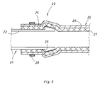
- FIG. 3 shows, likewise in a schematic sectional illustration, an exemplary embodiment of a pipeline connection 20 using a composite pipe 1 of the type shown in FIG. 1.
- a connector 21 with a connecting part 22 can be seen in the figure.
- This connector 21 can be made of any suitable material and the take a wide variety of forms, for example an angle tube, a T-piece or a tube end of another tube, also a composite tube 1 of the type shown in FIG. 1.
- the connecting part 22 is provided with an upstanding surface structure or an upstanding connecting element 23 which is designed such that it prevents the connected pipe end from sliding off after the connection has been made.
- the connecting element 23 forms a protruding projection which slopes steeply on one side and slopes away on the other side.
- the connecting element 23 can generally consist of a bead, bead, groove or knurling, which effectively prevents the connector 22 from sliding off.
- a pipe end 25 of a composite pipe 24 is pushed onto the connector part 22 on the outside; this tube end has been expanded, for example, by means of a conventional expanding mandrel to an inner diameter which is somewhat larger than the outer diameter of the connecting part 22.
- the composite tube 24 is constructed analogously to the composite tube 1 and consists of an outer tube 26 made of a metal which is corrosion-resistant under the conditions of use of the composite tube 24 and a thermoelastically stretched inner tube 27 made of a thermoelastic plastic and sealingly sealing the outer tube 26.
- a composite pipe 24 is connected to a T-shaped connecting piece 21 with three connecting parts 22 in accordance with the aforementioned type.
- T-shaped connecting piece 21 instead of the T-shaped connecting piece 21, other connecting pieces, for example angle pipes, can be used for this.
- Each connecting part 22 is provided with a plurality of connecting elements 23 which protrude from its circumference and are designed in such a way that they reliably prevent the connected pipe end 25 from sliding off after the connection has been made.
- the connecting elements 23 form annular members arranged axially at a distance on the circumference of the connecting part.
- the connecting elements 23 can also be designed in accordance with FIG. 3 with inclined surfaces and sloping edges or generally as a bead or bead, also as knurling, in such a way that sliding off the connecting part 22 is effectively prevented.
- the training can also be that at least one of the annular, upstanding connecting elements 23 is provided with knurling.
- the pipe end 25 of the composite pipe 24 is pushed onto the connecting part 22 via the connecting elements 23.
- this tube end 25 is expanded, for example by means of a conventional expanding mandrel, to an inner diameter which is somewhat larger than the outer diameter of the connecting part 22.
- the pipe end 25 pushed onto the connecting part 22 beyond the upstanding connecting elements 23 is pressed together with the connecting part 22 and is thereby held firmly thereon.
- This can be done with the help of the mechanically or hydraulically operated tools mentioned above, which cause deformation of the pipe end 25 and the connecting part 22 in the area of the attack, as a result of which a positive, secure connection is created between the two parts.
- the tendon 28 can be used, which engages around the pipe end 25 pushed on and is tightened.
- the exemplary embodiment shown additionally contains a securing ring 30 pushed onto the pipe end 25.
Landscapes
- Engineering & Computer Science (AREA)
- General Engineering & Computer Science (AREA)
- Mechanical Engineering (AREA)
- Manufacturing & Machinery (AREA)
- Rigid Pipes And Flexible Pipes (AREA)
- Non-Disconnectible Joints And Screw-Threaded Joints (AREA)
- Laminated Bodies (AREA)
- Lining Or Joining Of Plastics Or The Like (AREA)
- Mutual Connection Of Rods And Tubes (AREA)
- Quick-Acting Or Multi-Walled Pipe Joints (AREA)
- Branch Pipes, Bends, And The Like (AREA)
Abstract
Description
- Die Erfindung betrifft ein Verbundrohr aus einem Metall-Kunststoff-Verbundwerkstoff. Sie betrifft auch ein Verfahren zur Herstellung eines solchen Verbundrohres, bei dem aus einem thermoelastischen Kunststoff oberhalb dessen Kristallitschmelzpunkt mittels eines Strangpressverfahrens ein Rohr hergestellt, bei einer Temperatur oberhalb des Kristallitschmelzpunktes auf ein vorgegebenes Mass verstreckt und durch Abkühlen auf eine Temperatur unterhalb des Kristallitschmelzpunktes im verstreckten Zustand eingefroren wird.
- Die Erfindung betrifft auch eine Rohrleitungsverbindung aus einem Verbindungsstück mit einem Anschlussteil, das ein hochstehendes Verbindungselement enthält, und einem mit dem Anschlussteil zusammengepressten Rohrende.
- Die veröffentlichte europäische Patentanmeldung 82100466.0 betrifft ein Verfahren zur Herstellung von Kunststoffverformungen. Darin ist beschrieben, dass Kunststoffrohre aus thermoelastischem Material wie vernetztem Polyethylen im Strangpressverfahren hergestellt und anschliessend im heissen Zustand, nämlich bei einer Temperatur oberhalb des Kristallitschmelzpunktes dieses Materials, durch ein Formwerkzeug gefördert und anschliessend in einem Wasserbad abgekühlt werden. Das Formwerkzeug bewirkt dabei die Reduzierung des Polyethylenrohres in einem vorgegebenen Umfang in der Grössenordnung von 10 bis 20%.
- Das so erhaltene, verstreckte Material ist in seinem verstreckten Zustand eingefroren, ist aber thermoelastisch. Das bedeutet, dass das Material danach trachtet, sein ursprüngliches Mass wieder einzunehmen, wenn es über den Kristallitschmelzpunkt hinaus erwärmt wird. Diese Eigenschaft wird nach dieser Druckschrift unter anderem dazu genutzt, ein beschädigtes Rohr dadurch zu reparieren, dass ein im Durchmesser geringeres, verstrecktes Polyethylenrohr in den Beschädigungsbereich des Rohres eingeführt wird. Beim Erwärmen dieses Bereiches dehnt sich das verstreckte Polyethylenrohr auf sein ursprüngliches Mass aus und legt sich an das beschädigte Rohr in dessen Beschädigungsbereich an, wodurch die erwünschte Reparatur bewirkt wird.
- Weiterhin ist in der Druckschrift beschrieben, dass ein verstrecktes Innenrohr in ein Aussenrohr eingeführt und dieses an vorgegebenen Stellen erwärmt wird, sodass sich das Innenrohr an diesen Stellen an das Aussenrohr anlegt. Dabei werden thermisch isolierende Doppelrohre mit voneinander getrennten Isolierkammern gebildet.
- Bei einer bekannten Rohrleitungsverbindung insbesondere zwischen Verbindungsstücken aus Edelstahl oder Rotguss (Mannesmann AG; R.Nussbaum AG, CH-4601 Olten) und Edelstahlrohren enthält das Verbindungsstück ein Anschlussteil mit einer hochstehenden Sicke zur Aufnahme eines Dichtrings. Das Rohrende des zu verbindenden Edelstahlrohres wird in das Anschlussteil eingeführt, und das Rohrende und das Anschlussteil werden mittels eines mechanischen oder hydraulischen Presswerkzeugs zusammengepresst und dabei verformt, sodass eine formschlüssige, durch den Dichtring abgedichtete Verbindung entsteht.
- Rohre aus thermoelastischen Kunststoffen, insbesondere aus vernetzten Polyolefinen besitzen beispielsweise durch ihre Widerstandsfähigkeit gegen viele chemische Einflüsse und ihre hohen Standzeiten bis zu Temperaturen von 95°C hervorragende Eigenschaften, die sie zum Einsatz unter den unterschiedlichsten Bedingungen befähigen. Sie besitzen jedoch auch gewisse Nachteile dadurch, dass sie beispielsweise nicht diffusionsfest gegen Luftsauerstoff sind und bei ihrer Verformung gewisse Bedingungen einzuhalten sind, um Knickbildungen und dergleichen zu vermeiden.
- Die Aufgabe der Erfindung besteht darin, ein Verbundrohr zu schaffen, das die Korrosionsfestigkeit von Kunststoffen wie vernetzten Polyolefinen und die Dichtheit und Verformbarkeit von Metallen besitzt und daher nach den für Metallrohre üblichen Bearbeitungsmethoden bearbeitet werden kann, sowie ein Verfahren zur Herstellung solcher Verbundrohre anzugeben.
- Eine weitere Aufgabe der vorliegenden Erfindung besteht darin, eine Rohrleitungsverbindung unter Verwendung des vorgenannten Verbundrohres zu schaffen, die auf einfache Weise hergestellt werden kann und unter den verschiedensten Einsatzbedingungen fest und dicht ist.
- Hinsichtlich der Verbundrohre wird diese Aufgabe dadurch gelöst, dass das Verbundrohr aus einem Aussenrohr aus Metall und einem Innenrohr aus einem thermoelastischen Kunststoff besteht, der dem Aussenrohr über dessen gesamte Länge durch thermoelastische Dehnung abdichtend anliegt.
- Das erfindungsgemässe Verbundrohr ist dadurch ausgezeichnet, dass sein Aussenrohr aus Metall besteht. Vorzugsweise ist das Metall aus unter den Einsatzbedingungen korrosionsfesten Metallen, z.B. Edelstahl ausgewählt. Dadurch erhält das Verbundrohr die schätzenswerten Eigenschaften des Metalls, d.h. die Wärmeausdehnung ist nicht grösser als bei Metallen, die Bearbeitung erfolgt mit den für Metalle üblichen Werkzeugen unter den für Metalle üblichen Bearbeitungsbedingungen und das Verbundrohr ist diffusionsfest, da das Metall gegen das Eindringen von Luftsauerstoff oder Geruchsstoffen von aussen schützt. Diese Eigenschaften sind beispielsweise für Trinkwasserleitungen und Heisswasserleitungen, aber auch generell für im Sanitätbereich verlegte oder zu verlegende Wasserleitungen von Bedeutung.
- Andererseits ist das erfindungsgemässe Verbundrohr dadurch ausgezeichnet, dass das Innenrohr aus dem thermoelastischen Kunststoff besteht und somit dessen hohe Korrosionsfestigkeit gegen die unterschiedlichsten chemischen Einflüsse und auch dessen hohe Standzeiten besitzt. Durch das Herstellungsverfahren, bei dem die Selbst-Rückverformung des verstreckten Innenrohres ausgenutzt wird, um bei der Rückverformung eine dichtende Anlage an das Aussenrohr zu erzielen, ist einerseits sichergestellt, dass das Aussenrohr nicht in Berührung mit dem durch das Innenrohr fliessende Medium kommt, wie auch andererseits das Metallrohr das Medium, das durch das Innenrohr fliesst, gegen das Eindringen von schädlichen oder unerwünschten Stoffen schützt.
- Schliesslich ist auch zu berücksichtigen, dass die Ummantelung des Kunststoffrohres durch das Metallrohr eine erhöhte Feuersicherheit bewirkt, da das freie Kunststoffrohr, das ja aus Kohlenstoffverbindungen besteht, bei entsprechend hohen Temperaturen brennbar ist.
- Es hat sich darüberhinaus ebenfalls gezeigt, dass die unterschiedlichen thermischen Eigenschaften der thermoelastischen Kunststoffe und des Metalls keine Rolle spielen. Einerseits besitzt das Aussenrohr aus Metall genügende mechanische Festigkeit, um thermisch verursachten Formänderungen des Innenrohres zu widerstehen. Andererseits wirkt sich die stärkere thermische Verformung des Innenrohres so aus, dass lediglich geringe Wandstärkenänderungen auftreten, die den Durchfluss des Mediums durch das Innenrohr nicht beeinträchtigen. Die Verbindung zwischen dem Innenrohr und dem Aussenrohr ist so fest, dass die stärkeren thermischen Verformungen des Innenrohres nicht dazu führen, dass sich dieses aus der dichten Anlage an dem Aussenrohr löst.
- Hinsichtlich des erfindungsgemässen Verfahrens wird die vorgenannte Aufgabe dadurch gelöst, dass das verstreckte Rohr als Innenrohr in ein Aussenrohr aus Metall über dessen gesamte Länge eingeführt wird, wobei der Innendurchmesser des Aussenrohres grösser als der Aussendurchmesser des verstreckten Innenrohres, aber kleiner als der Aussendurchmesser des unverstreckten Innenrohres ist, dass das Aussenrohr mit dem darin befindlichen verstreckten Innenrohr über seine gesamte Länge auf eine Temperatur oberhalb des Kristallitschmelzpunktes des thermoeleastischen Kunststoffs erwärmt wird, wodurch das verstreckte Innenrohr durch Selbst-Rückverformung sein unverstrecktes Mass anzunehmen trachtet und sich bis zu dichtender Anlage an das Aussenrohr ausdehnt, und dass das so erhaltene Verbundrohr auf Umgebungstemperatur abkühlen gelassen wird.
- Hinsichtlich der Rohrleitungsverbindung wird die vorgenannte Aufgabe dadurch gelöst, dass dass das Rohrende von einem Verbundrohr gebildet ist, das aus einem Aussenrohr aus Metall und einem thermoelastisch gedehnten, dem Aussenrohr über dessen gesamte Länge durch die thermoelastische Dehnung abdichtend anliegenden Innenrohr aus einem thermoelastischen Kunststoff besteht, und dass das aufgeweitete Rohrende über das hochstehende Verbindungselement hinweg aussen auf das Anschlussteil aufgeschoben ist.
- Bei der so erhaltenen Rohrleitungsverbindung liegt das Rohrende des Verbundrohres mit dem Innenrohr aus thermoelastischen Kunststoff aussen an dem Anschlussteil an. Dadurch entsteht eine so dichte Verbindung, dass auf die Einlage des nach dem Stand der Technik notwendingen Dichtrings verzichtet werden kann.
- Vorteilhafterweise enthält das Anschlussteil mehrere hochstehende Verbindungselemente, über die das aufgeweitete Rohrende hinweg aussen auf das Anschlussteil aufgeschoben wird. Es lässt sich so eine erhöhte Sicherheit und Dichtheit der Rohrleitungsverbindung erzielen.
- Vorteilhafte Weiterbildungen des erfindungsgemässen Verbundrohres und des Verfahrens nach der Erfindung sind in Unteransprüchen gekennzeichnet.
- Ausführungsbeispiele der Erfindung sind in den Abbildungen dargestellt und werden nachstehend an Hand der Bezugszeichen im einzelnen beschrieben. Es zeigen
- Figur 1
- eine schematische Schnittdarstellung eines erfindungsgemässen Verbundrohres; und
- Figur 2
- eine schematische Darstellung einer Anlage zur Durchführung eines Ausführungsbeispiels des Verfahrens nach der Erfindung;
- Figur 3
- eine schematische Schnittdarstellung eines Ausführungsbeispiels einer erfindungsgenmässen Rohrleitungsverbindung unter Verwendung des Verbundrohres nach Figur 1;
- Figur 4
- eine Ansicht eines weiteren Ausführungsbeispiels der erfindungsgemässen Rohrleitungsverbindung vor der Herstellung der Verbindung; und
- Figur 5
- eine Ansicht einer fertigen Rohrleitungsverbindung nach Figur 4.
- In der Schnittdarstellung von Figur 1 erkennt man ein Verbundrohr 1, das aus einem Aussenrohr 2 und einem Innenrohr 3 aufgebaut ist. Das Aussenrohr besteht aus einem Metall, das unter den Einsatzbedingungen des Verbundrohres 1 korrosionsfest ist. In dem dargestellten Ausführungsbeispiel besteht das Aussenrohr 2 aus Edelstahl oder rostfreiem Stahl der Sorte 14571 (X6CrNiMo17122), die unter sauren Bedingungen korrosionsfest ist. Unter anderen Einsatzbedingungen werden dementsprechend gewählte Stahlsorten und gegebenenfalls auch andere Metalle oder Metallegierungen eingesetzt. Die Auswahl erfolgt darüberhinaus unter dem Gesichtspunkt der Festigkeit und der thermischen Ausdehnung (s.w.u.)
- Das Innenrohr 3 besteht aus einem thermoelastischen Kunststoff. Darunter wird ein Kunststoff verstanden, der bei erhöhter Temperatur erweicht, sodass er relativ leicht verformbar ist, und nach der Verformung bei der erhöhten Temperatur und Abkühlung auf Umgebungstemperatur seine Form beibehält, aber beim Erwärmen auf die Verformungstemperatur infolge der dabei eintretenden Erweichung einer Selbst-Rückverformung in die ursprüngliche Form unterliegt. Ein bevorzugtes Beispiel für solche thermoelastischen Kunststoffe sind die vernetzten Polyolefine. In dem dargestellten Ausführungsbeispiel besteht das Innenrohr 3 aus vernetztem Polyethylen.
- Vernetztes Polyethylen erweicht bei Temperaturen im Bereich von 140°C bis 160°C und kann in diesem Temperaturbereich leicht verformt, beispielsweise gestreckt werden. Wird das gestreckte Material abgekühlt, so behält es bei Umgebungstemperatur die gestreckte Form. Die Ursache dafür liegt darin, dass vernetztes Polyethylen und vernetzte Polyolefine allgemein aus amorphen und kristallinen Anteilen bestehen; beim Erwärmen auf die oben genannte Temperatur schmelzen die kristallinen Anteile, wodurch die Erweichung und die Verformbarkeit entstehen. Beim Abkühlen unter den Kristallitschmelzpunkt ist die Verformung nicht oder nur sehr schwer zu bewirken. Wird das gestreckte Material jedoch wieder auf eine Temperatur oberhalb des Kristallitschmelzpunktes erwärmt, so trachtet das Material danach, seine ursprüngliche Form wieder anzunehmen und die Streckung rückgängig zu machen.
- In dem dargestellten Ausführungsbeispiel bedeutet das, dass das gestreckte Innenrohr 3 sich auf seine ursprünglichen, ungestreckten Abmessungen auszudehnen trachtet. Bei diesem Ausführungsbeispiel hat das Aussenrohr 2 einen Innendurchmesser von 39,6 mm, eine Wandstärke von 0,2 mm und einen Aussendurchmesser von 40 mm. Das Innenrohr 3 hatte bei seiner Herstellung einen Aussendurchmesser von 40 mm und war bis auf einen Aussendurchmesser von 35 mm gestreckt worden. Nach seiner Einführung in das Aussenrohr 2 wurde wieder über den Kritallitschmelzpunkt erwärmt. Das hat zur Folge, dass sich das Innenrohr 3 wieder auf seine ursprüngliche Form thermisch auszudehnen trachtet. Der vollständigen Selbst-Rückverformung steht jedoch der geringere Innendurchmesser (39,6 mm) des Aussenrohres 2 entgegen. Dadurch kommt das Innenrohr 3 in eine sehr enge, abdichtende Anlage an die Innenwand des Aussenrohres 2, wie in Figur 1 dargestellt ist.
- Es ergibt sich so, dass das Aussenrohr 1 aus einem Metall hergestellt sein muss, das ausreichende Festigkeit gegenüber den Kräften besitzt, die bei der Selbst-Rückverformung des Innenrohres 3 auftreten. Weiterhin muss das Metall des Aussenrohres 2 einer geringeren Wärmedehnung unterliegen als das Innenrohr 3, da andernfalls eine unerwünschte Ablösung des Innenrohres 3 von der Innenwand des Aussenrohres 2 ermöglicht würde.
- Bei besonderen Anwendungsfällen, bei denen eine Aufweitung des Aussenrohres 2 auf einen Innendrchmesser über 40 mm unter Wärmeeinwirkung erfolgt, sodass die Gefahr einer Ablösung des Innenrohres 3 von der Innenwand des Aussenrohres 2 besteht, kann dies durch Anwendung eines Haftvermittlers verhindert werden, der zwischen dem Innenrohr 3 und dem Aussenrohr 2 angeordnet wird. Solche Haftvermittler zwischen vernetzten Polyolefinen oder anderen thermoelastischen Kunststoffen und den verschiedensten Metallen sind an sich bekannt und im Handel erhältlich.
- Figur 2 zeigt eine schematische Darstellung einer Anlage zur Herstellung von Verbundrohren der Art, wie sie in Figur 1 dargestellt ist. Man erkennt auf der linken Seite der Abbildung eine Fördervorrichtung 10, die beispielsweise ein Rollenförderer sein kann und die dazu dient, ein Aussenrohr 11 zu einem Wärmeofen 13 zu fördern. Zusammen mit dem Aussenrohr 11 wird dem Wärmeofen 13 ein Innenrohr 12 aus gestrecktem, vernetzten Polyolefin oder einem anderen thermoelastischen Kunststoff zugeführt. Dieses Innenrohr 12 hat eine ausreichende Festigkeit, sodass für seine Förderung keine besonderen Haltemittel vorgesehen werden müssen. Ausserdem kommt es bei diesem Verfahren nicht auf eine exakt koaxiale oder zentrierte Orientierung des Innenrohres 12 relativ zu dem Aussenrohr 11 an. Die Ursache dafür liegt darin, dass die Abmessungen der beiden Rohre so gewählt sind, dass in jedem Fall sichergestellt ist, dass das Innenrohr 12 bei der Wärmebehandlung in enge, dichtende Anlage an die Innenwand des Aussenrohres 12 kommt.
- Der Wärmeofen 13 ist als Durchlaufofen konstruiert, durch den die Rohrkombination aus dem Aussenrohr 11 und dem Innenrohr 12 kontinuierlich gefördert wird. Der Wärmeofen 13 enthält dazu Heizelemente 14, die zur Beheizung des Durchlaufraumes dienen. Die Wärmeerzeugung durch die Heizelemente 14 und die Durchlaufgeschwindigkeit der Rohre 11 und 12 sind so aufeinander abgestimmt, dass die Erwärmung ausreicht, um die thermoelastische Dehnung des Innenrohres 12 zu bewirken.
- Die Heizelemente 14 können beispielsweise als Widerstandselemente, als Infrarotstrahler oder auch als Gasbrenner ausgebildet sein; auch kann der Wärmeofen 13 einen Induktionsofen bilden.
- An der Ausgangsseite des Wärmeofens 13 tritt dann das Verbundrohr 15 aus, dass von einer weiteren Fördervorrichtung 16, die wiederum ein Rollenförderer sein kann, aufgenommen und einer Weiterverarbeitungseinrichtung zugeführt wird. Diese Einrichtung kann beispielsweise eine Schneidvorrichtung bekannter Bauart sein, durch die das Verbundrohr 15 auf die jeweils gewünschten Längen geschnitten wird.
- Der vorstehend beschriebene Wärmeofen 13 ist als Durchlaufofen für den kontinuierlichen Betrieb eingerichtet. Es können stattdessen aber auch vorgegebene Längen von Aussenrohren 11 und Innenrohren 12 diskontinuierlich in einem entsprechend gestalteten Wärmeofen auf eine Temperatur oberhalb des Kristallitschmelzpunktes des Innenrohres 12 erwärmt werden, um die entsprechenden Längen des Verbundrohres 15 herzustellen.
- Die Ausdehnung und Anlage des Innenrohres 12 an die Innenwand des Aussenrohres 11 kann bei der diskontinuierlichen Betriebsweise zusätzlich dadurch unterstützt werden, dass das Innenrohr 12 an einem Ende geschlossen und am anderen Ende mit einem Heissfluid, zum Beispiel Heissdampf beaufschlagt wird. Der sich dabei im Innenrohr 12 aufbauende Innendruck bewirkt, dass das sich thermoelastisch dehnende Innenrohr 12 gegen die Innenwand des Aussenrohres 11 gepresst wird.
- Figur 3 zeigt, ebenfalls in einer schematischen Schnittdarstellung, ein Ausführungsbeispiel einer Rohrleitungsverbindung 20 unter Verwendung eines Verbundrohres 1 nach Art der Figur 1. Man erkennt in der Abbildung ein Verbindungsstück 21 mit einem Anschlussteil 22. Dieses Verbindungsstück 21 kann aus jedem geeigneten Material bestehen und die unterschiedlichsten Formen annehmen, zum Beispiel ein Winkelrohr, ein T-Stück oder auch ein Rohrende eines anderen Rohres, auch eines Verbundrohres 1 nach Art der Figur 1 sein. Das Anschlussteil 22 ist mit einer hochstehenden Oberflächenstruktur bzw. einem hochstehenden Verbindungselement 23 versehen, das so ausgebildet ist, dass es ein Abgleiten des verbundenen Rohrendes nach Herstellung der Verbindung verhindert. In dem dargestellten Ausführungsbeispiel bildet das Verbindungselement 23 einen hochstehenden, auf einer Seite steil und auf der anderen Seite schräg abfallenden Vorsprung. Das Verbindungslelement 23 kann allgemein aus einer Wulst, Sicke, Rille oder Rändelung bestehen, die das Abgleiten von dem Anschlussteil 22 wirksam verhindert.
- Auf das Anschlussteil 22 ist aussen ein Rohrende 25 eines Verbundrohres 24 aufgeschoben; dieses Rohrende ist beispielsweise mittels eines üblichen Spreizdorns auf einen Innendurchmesser aufgeweitet worden, der etwas grösser ist als der Aussendurchmesser des Anschlussteils 22. Das Verbundrohr 24 ist analog dem Verbundrohr 1 aufgebaut und besteht aus einem Aussenrohr 26 aus einem unter den Einsatzbedingungen des Verbundrohres 24 korrosionsfesten Metall und einem thermoelastisch gedehnten, dem Aussenrohr 26 abdichtend anliegenden Innenrohr 27 aus einem thermoelastischen Kunststoff.
- Das über das hochstehende Verbindungselement 23 hinaus auf das Anachlussteil 22 aufgeschobene Teil des Rohrendes 25 ist mit dem Anschlussteil 22 zusammengepresst und dadurch fest an diesem gehalten. Dies kann mit Hilfe der eingangs erwähnten, mechanisch oder hydraulisch betätigten Werkzeuge geschehen, die im Angriffsbereich eine Verformung des Rohrendes 25 und des Anschlussteils 22 bewirken, wodurch eine formschlüssige, sichere Verbindung zwischen den beiden Teilen entsteht. Stattdessen kann aber auch ein Spannglied 28 verwendet werden, welches das aussen aufgeschobene Rohrende 25 umgreift und angezogen wird. Solche Spannglieder 28 sind an sich bekannt und daher hier nur schematisch angedeutet; es kann beispielsweise dafür eine Rohrschelle verwendet werden.
- Zur Herstellung einer weiteren Rohrleitungsverbindung 20 nach Figur 4 wird ein Verbundrohr 24 entsprechend der vorgenannten Art einem T-förmigen Verbindungsstück 21 mit drei Anschlussteilen 22 verbunden. Statt des T-förmigen Verbindungsstücks 21 können dafür andere Verbindungsstücke, zum Beispiel Winkelrohre, eingesetzt werden.
- Jedes Anschlussteil 22 ist mit mehreren, von seinem Umfang hochstehenden Verbindungselementen 23 versehen, die so ausgebildet sind, dass sie ein Abgleiten des verbundenen Rohrendes 25 nach Herstellung der Verbindung sicher verhindern. In dem dargestellten Ausführungsbeispiel bilden die Verbindungselemente 23 axial im Abstand am Umfang des Anschlussteils angeordnete, ringförmige Glieder. Die Verbindungselemente 23 können aber auch entsprechend Figur 3 mit Schrägflächen und abfallenden Kanten oder allgemein als Wulst oder Sicke, auch als Rändelung so ausgebildet sein, dass ein Abgleiten von dem Anschlussteil 22 wirksam verhindert wird. Die Ausbildung kann auch so sein, dass mindestens eines der ringförmigen, hochstehenden Verbindungselemente 23 mit einer Rändelung versehen ist.
- Wie in Figur 5 erkennbar ist, ist in der fertigen Rohrleitungsverbindung 20 das Rohrende 25 des Verbundrohres 24 auf das Anschlussteil 22 über die Verbindungselemente 23 hinweg aufgeschoben. Dazu wird dieses Rohrende 25 beispielsweise mittels eines üblichen Spreizdorns auf einen Innendurchmesser aufgeweitet, der etwas grösser ist als der Aussendurchmesser des Anschlussteils 22.
- Das über die hochstehenden Verbindungselemente 23 hinaus auf das Anschlussteil 22 aufgeschobene Rohrende 25 ist mit dem Anschlussteil 22 zusammengepresst und wird dadurch fest daran gehaltert. Dies kann mit Hilfe der vorstehend erwähnten, mechanisch oder hydraulisch betätigten Werkzeuge geschehen, die im Angriffsbereich eine Verformung des Rohrendes 25 und des Anschlussteils 22 bewirken, wodurch eine formschlüssige, sichere Verbindung zwischen den beiden Teilen entsteht. Stattdessen kann aber auch das Spannglied 28 verwendet werden, welches das aussen aufgeschobene Rohrende 25 umgreift und angezogen wird.
- Das dargestellte Ausführungsbeispiel enthält zusätzlich einen auf das Rohrende 25 aufgeschobenen Sicherungsring 30.
Claims (32)
- Verbundrohr (1,15,24) aus einem Metall-Kunststoff-Verbundwerkstoff, bestehend aus einem Aussenrohr (2,11,26) aus Metall und einem Innenrohr (3,12,27) aus einem thermoelastischen Kunststoff, der dem Aussenrohr (2,11,26) über dessen gesamte Länge durch thermoelastische Dehnung abdichtend anliegt.
- Verbundrohr nach Anspruch 1, dadurch gekennzeichnet, dass das Aussenrohr (2,11,26) aus einem unter den Einsatzbedingungen korrosionsfesten Metall gebildet ist.
- Verbundrohr nach Anspruch 2, dadurch gekennzeichnet, dass das Aussenrohr (2,11,26) aus Edelstahl besteht.
- Verbundrohr nach Anspruch 2 oder 3, dadurch gekennzeichnet, dass das Aussenrohr (2,11,26) einen thermischen Ausdehnungskoeffizienten hat, der kleiner ist als der des Innenrohres (3,12,27).
- Verbundrohr nach einem der Ansprüche 1 bis 4, dadurch gekennzeichnet, dass der thermoelastische Kunststoff aus einem thermoelastischen Polyolefin besteht.
- Verbundrohr nach Anspruch 5, dadurch gekennzeichnet, dass das thermoelastische Polyolefin aus unvernetztem oder vernetztem Polyolefin ausgewählt ist.
- Verbundrohr nach einem der Ansprüche 1 bis 6, dadurch gekennzeichnet, dass zwischen dem Aussenrohr (2,11,26) und dem Innenrohr (3,12,27) ein Haftvermittler angeordnet ist.
- Verfahren zur Herstellung eines Verbundrohres nach einem der vorstehenden Ansprüche, bei dem aus einem thermoelastischen Kunststoff oberhalb dessen Kristallitschmelzpunkt mittels eines Strangpressverfahrens ein Rohr hergestellt, bei einer Temperatur oberhalb des Kristallitschmelzpunktes auf ein vorgegebenes Mass gestreckt und durch Abkühlen auf eine Temperatur unterhalb des Kristallitschmelzpunktes im gestreckten Zustand eingefroren wird,
dadurch gekennzeichnet, dass das verstreckte Rohr als Innenrohr (12) in ein Aussenrohr (11) aus Metall über dessen gesamte Länge eingeführt wird, wobei der Innendurchmesser des Aussenrohres (11) grösser als der Aussendurchmesser des gestreckten Innenrohres (12), aber kleiner als der Aussendurchmesser des ungestreckten Innenrohres (12) ist, dass das Aussenrohr (11) mit dem darin befindlichen gestreckten Innenrohr (12) über seine gesamte Länge auf eine Temperatur oberhalb des Kristallitschmelzpunktes des thermoeleastischen Kunststoffs erwärmt wird, wodurch das gestreckte Innenrohr (12) durch Selbst-Rückverformung sein ungestrecktes Mass anzunehmen trachtet und sich bis zu dichtender Anlage an das Aussenrohr (11) ausdehnt, und dass das so erhaltene Verbundrohr (15) auf Umgebungstemperatur abkühlen gelassen wird. - Verfahren nach Anspruch 8, dadurch gekennzeichnet, dass das Aussenrohr (11) mit dem darin befindlichen gestreckten Innenrohr (12) kontinuierlich durch einen Wärmeofen (13) gefördert und dadurch auf eine Temperatur oberhalb des Kristallitschmelzpunktes des thermoelastischen Kunststoffs erwärmt wird.
- Verfahren nach Anspruch 8, dadurch gekennzeichnet, dass das Aussenrohr (11) mit dem darin befindlichen gestreckten Innenrohr (12) durch Infrarotstrahlung auf eine Temperatur oberhalb des Kristallitschmelzpunktes des thermoelastischen Kunststoffs erwärmt wird.
- Verfahren nach Anspruch 8, dadurch gekennzeichnet, dass das Aussenrohr (11) mit dem darin befindlichen gestreckten Innenrohr (12) durch ein Heissfluid auf eine Temperatur oberhalb des Kristallitschmelzpunktes des thermoelastischen Kunststoffs erwärmt wird.
- Verfahren nach Anspruch 11, dadurch gekennzeichnet, dass das Heissfluid unter Druck auf das gestreckte Innenrohr (12) zur Einwirkung gebracht und das Innenrohr (12) durch Selbst-Rückverformung und unter dem Druck des Heissfluids an das Aussenrohr (11) angelegt wird.
- Verfahren nach einem der Ansprüche 8 bis 12, dadurch gekennzeichnet, dass das Aussenrohr (11) aus unter den Einsatzbedingungen korrosionsfesten Metallen ausgewählt wird.
- Verfahren nach Anspruch 13, dadurch gekennzeichnet, dass das Aussenrohr (11) aus Edelstahl besteht.
- Verfahren nach Anspruch 13, dadurch gekennzeichnet, dass das Aussenrohr (11) aus einem Metall mit einem thermischen Ausdehnungskoeffizienten gefertigt wird, der kleiner ist als der des Innenrohres (12).
- Verfahren nach einem der Ansprüche 8 bis 14, dadurch gekennzeichnet, dass das Innenrohr (12) aus thermoelastischen Polyolefinen ausgewählt wird.
- Verfahren nach Anspruch 16, dadurch gekennzeichnet, dass das thermoelastische Polyolefin aus unvernetztem oder vernetztem Polyolefin ausgewählt wird.
- Verfahren nach einem der Ansprüche 8 bis 17, dadurch gekennzeichnet, dass vor der Erwärmung auf das Innenrohr (12) und/oder das Aussenrohr (11) ein Haftvermittler aufgetragen wird.
- Rohrleitungsverbindung (20) aus einem Verbindungsstück (21) mit einem Anschlussteil (22), das ein hochstehendes Verbindungselement (23) enthält, und einem mit dem Anschlussteil (22) zusammengepressten Rohrende (25),
dadurch gekennzeichnet, dass das Rohrende (25) von einem Verbundrohr (24) gebildet ist, das aus einem Aussenrohr (26) aus Metall und einem thermoelastisch gedehnten, dem Aussenrohr (26) über dessen gesamte Länge durch die thermoelastische Dehnung abdichtend anliegenden Innenrohr (27) aus einem thermoelastischen Kunststoff besteht, und dass das aufgeweitete Rohrende (25) über das hochstehende Verbindungselement (23) hinweg aussen auf das Anschlussteil (22) aufgeschoben ist. - Rohrleitungsverbindung nach Anspruch 19, dadurch gekennzeichnet, dass das Aussenrohr (26) aus einem unter den Einsatzbedingungen korrosionsfesten Metall gebildet ist.
- Rohrleitungsverbindung nach Anspruch 20, dadurch gekennzeichnet, dass das Aussenrohr (26) aus Edelstahl besteht.
- Verbundrohr nach Anspruch 20 oder 21, dadurch gekennzeichnet, dass das Aussenrohr (26) einen thermischen Ausdehnungskoeffizienten hat, der kleiner ist als der des Innenrohres (27).
- Rohrleitungsverbindung nach einem der Ansprüche 19 bis 22, dadurch gekennzeichnet, dass der thermoelastische Kunststoff aus einem thermoelastischen Polyolefin besteht.
- Rohrleitungsverbindung nach Anspruch 23, dadurch gekennzeichnet, dass das thermoelastische Polyolefin aus unvernetztem oder vernetztem Polyolefin ausgewählt ist.
- Rohrleitungsverbindung nach einem der Ansprüche 19 bis 24, dadurch gekennzeichnet, dass zwischen dem Aussenrohr (26) und dem Innenrohr (27) ein Haftvermittler angeordnet ist.
- Rohrleitungsverbindung nach einem der Ansprüche 19 bis 25, dadurch gekennzeichnet, dass das Verbindungselement (23) aus der Gruppe Wulst, Sicke, Rille, Rändelung ausgewählt ist.
- Rohrleitungsverbindung nach einem der Ansprüche 19 bis 26, dadurch gekennzeichnet, dass das Verbindungsstück (21) mit dem Anschlussteil (22) aus einem Verbundwerkstoff gebildet ist, der aus einem Aussenrohr aus Metall und einem thermoelastisch gedehnten, dem Aussenrohr über dessen gesamte Länge durch die thermische Dehnung abdichtend anliegenden Innenrohr aus einem thermoelastischen Kunststoff besteht.
- Rohrleitungsverbindung nach einem der Ansprüche 19 bis 27, dadurch gekennzeichnet, dass das Verbindungsstück (21) ein Verbundrohr (1) und das Anschlussteil ein Rohrende aus dem Verbundwerkstoff ist.
- Rohrleitungsverbindung nach einem der Ansprüche 19 bis 28, dadurch gekennzeichnet, dass dass das Anschlussteil (22) meherere hochstehende Verbindungselemente (23) enthält, über die das aufgeweitete Rohrende hinweg aussen auf das Anschlussteil (22) aufgeschoben wird.
- Rohrleitungsverbindung nach Anspruch 29, dadurch gekennzeichnet, dass die hochstehenden Verbindungselemente (23) vom Umfang des Anschlussteils (22) hochstehend ausgebildet und axial in vorgegebenen Abständen voneinander an dem Anschlussteil (22) angeordnet sind.
- Rohrleitungsverbindung nach einem der Ansprüche 29 oder 30, dadurch gekennzeichnet, dass wenigstens eines der hochstehenden Verbindungselemente (23) mit einer Rändelung versehen ist.
- Rohrleitungsverbindung nach einem der Ansprüche 29 bis 31, dadurch gekennzeichnet, dass die hochstehenden Verbindungselemente (23) ringförmig ausgebildet sind und ein auf das Rohrende aufgeschobener Sicherungsring (30) vorgesehen ist.
Applications Claiming Priority (4)
| Application Number | Priority Date | Filing Date | Title |
|---|---|---|---|
| DE4130167 | 1991-09-11 | ||
| DE19914130167 DE4130167A1 (de) | 1991-09-11 | 1991-09-11 | Verbundrohr und verfahren zu seiner herstellung und rohrleitungsverbindung aus dem verbundrohr |
| DE4217538A DE4217538A1 (de) | 1991-09-11 | 1992-05-27 | Rohrleitungsverbindung aus einem Verbundrohr |
| DE4217538 | 1992-05-27 |
Publications (3)
| Publication Number | Publication Date |
|---|---|
| EP0531790A2 true EP0531790A2 (de) | 1993-03-17 |
| EP0531790A3 EP0531790A3 (en) | 1993-10-13 |
| EP0531790B1 EP0531790B1 (de) | 1998-04-22 |
Family
ID=25907193
Family Applications (1)
| Application Number | Title | Priority Date | Filing Date |
|---|---|---|---|
| EP92114451A Expired - Lifetime EP0531790B1 (de) | 1991-09-11 | 1992-08-25 | Rohrleitungsverbindung für ein Verbundrohr |
Country Status (5)
| Country | Link |
|---|---|
| EP (1) | EP0531790B1 (de) |
| AT (1) | ATE165432T1 (de) |
| DE (2) | DE4217538A1 (de) |
| DK (1) | DK0531790T3 (de) |
| ES (1) | ES2117021T3 (de) |
Cited By (10)
| Publication number | Priority date | Publication date | Assignee | Title |
|---|---|---|---|---|
| DE29713049U1 (de) * | 1997-07-23 | 1997-09-18 | Unicor Rohrsysteme GmbH, 97437 Haßfurt | Verbundrohr |
| WO1998050725A1 (en) * | 1997-05-03 | 1998-11-12 | Advanced Engineering Solutions Limited | Method of lining pipes |
| DE19731580A1 (de) * | 1997-07-23 | 1999-01-28 | Unicor Rohrsysteme Gmbh | Verbundrohr |
| EP1122009A1 (de) * | 2000-02-07 | 2001-08-08 | Franz Viegener II GmbH & Co. KG. | Vorrichtung und Verfahren zur Entfernung der Metallschicht an einem Ende eines mehrschichtigen Metall-Kunststoffrohres zur Vorbereitung zum Aufnehmen einer Pressverbindung |
| WO2009018721A1 (fr) * | 2007-08-09 | 2009-02-12 | Mingwei Zhang | Équipement et procédé de fabrication de conduite composite acier/plastique |
| EP2118550A2 (de) * | 2007-01-22 | 2009-11-18 | John Frederick Olson | Mit elastomer ausgekleidetes abriebfestes rohr und herstellungsverfahren dafür |
| GB2540422A (en) * | 2015-07-17 | 2017-01-18 | Rolls Royce Plc | Fluid conduit liner |
| CN107584742A (zh) * | 2017-07-28 | 2018-01-16 | 山西华星管业科技有限公司 | 超高分子量聚乙烯管材的生产方法及其使用的挤出机机模 |
| CN107654760A (zh) * | 2017-10-04 | 2018-02-02 | 英立(江苏)机电有限公司 | 一种具有阻燃功能的pe燃气管道 |
| CN107961741A (zh) * | 2014-05-26 | 2018-04-27 | 英尼奥斯欧洲股份公司 | 用于酸添加的进口喷嘴 |
Families Citing this family (5)
| Publication number | Priority date | Publication date | Assignee | Title |
|---|---|---|---|---|
| DE19536598C2 (de) * | 1995-09-19 | 2000-01-13 | Mannesmann Ag | Rohrverbindung |
| DE20104340U1 (de) * | 2001-03-14 | 2002-07-25 | Uponor Innovation Ab, Fristad | Kunststoffrohr |
| PT103638B (pt) * | 2007-01-11 | 2007-06-06 | Duofil Sociedade Com E Ind De | Processo de montagem de uma união para condutas tubulares e respectiva união |
| CN102022588A (zh) * | 2010-08-27 | 2011-04-20 | 广东联塑科技实业有限公司 | 一种衬塑钢塑复合管及其制造方法 |
| CN107449153A (zh) * | 2017-08-18 | 2017-12-08 | 合肥荣电环境电器有限公司 | 一种家用热水器的内胆水管连接装置 |
Citations (9)
| Publication number | Priority date | Publication date | Assignee | Title |
|---|---|---|---|---|
| GB1124540A (en) * | 1965-10-11 | 1968-08-21 | Upjohn Co | Metal clad plastics piping |
| FR2191058A1 (de) * | 1972-06-27 | 1974-02-01 | Btr Industries Ltd | |
| AU6548174A (en) * | 1973-02-09 | 1975-08-14 | Juralco Pty. Limited | Drawing thermoplastics tubing |
| DE2531785A1 (de) * | 1975-07-16 | 1977-01-20 | Teleflex Gmbh | Verfahren zur herstellung eines verbundrohres |
| EP0241297A2 (de) * | 1986-04-11 | 1987-10-14 | Du Pont (UK) Limited | Herstellung eines mit thermoplastischem Polymermaterial ausgekleideten Rohres |
| EP0254489A2 (de) * | 1986-07-24 | 1988-01-27 | BP Chemicals Limited | Verfahren zum Auskleiden von Rohren |
| WO1991002918A1 (en) * | 1989-08-22 | 1991-03-07 | British Gas Plc | Pipe joint |
| WO1992009840A1 (de) * | 1990-11-30 | 1992-06-11 | Hewing Gmbh | Rohrverbindung, insbesondere an verbundrohren |
| US5135698A (en) * | 1991-05-28 | 1992-08-04 | Conoco Inc. | Lining of pipelines using a continuous tubular pull-through plastic liner |
-
1992
- 1992-05-27 DE DE4217538A patent/DE4217538A1/de not_active Withdrawn
- 1992-08-25 DE DE59209296T patent/DE59209296D1/de not_active Expired - Fee Related
- 1992-08-25 ES ES92114451T patent/ES2117021T3/es not_active Expired - Lifetime
- 1992-08-25 DK DK92114451T patent/DK0531790T3/da active
- 1992-08-25 AT AT92114451T patent/ATE165432T1/de not_active IP Right Cessation
- 1992-08-25 EP EP92114451A patent/EP0531790B1/de not_active Expired - Lifetime
Patent Citations (9)
| Publication number | Priority date | Publication date | Assignee | Title |
|---|---|---|---|---|
| GB1124540A (en) * | 1965-10-11 | 1968-08-21 | Upjohn Co | Metal clad plastics piping |
| FR2191058A1 (de) * | 1972-06-27 | 1974-02-01 | Btr Industries Ltd | |
| AU6548174A (en) * | 1973-02-09 | 1975-08-14 | Juralco Pty. Limited | Drawing thermoplastics tubing |
| DE2531785A1 (de) * | 1975-07-16 | 1977-01-20 | Teleflex Gmbh | Verfahren zur herstellung eines verbundrohres |
| EP0241297A2 (de) * | 1986-04-11 | 1987-10-14 | Du Pont (UK) Limited | Herstellung eines mit thermoplastischem Polymermaterial ausgekleideten Rohres |
| EP0254489A2 (de) * | 1986-07-24 | 1988-01-27 | BP Chemicals Limited | Verfahren zum Auskleiden von Rohren |
| WO1991002918A1 (en) * | 1989-08-22 | 1991-03-07 | British Gas Plc | Pipe joint |
| WO1992009840A1 (de) * | 1990-11-30 | 1992-06-11 | Hewing Gmbh | Rohrverbindung, insbesondere an verbundrohren |
| US5135698A (en) * | 1991-05-28 | 1992-08-04 | Conoco Inc. | Lining of pipelines using a continuous tubular pull-through plastic liner |
Cited By (14)
| Publication number | Priority date | Publication date | Assignee | Title |
|---|---|---|---|---|
| WO1998050725A1 (en) * | 1997-05-03 | 1998-11-12 | Advanced Engineering Solutions Limited | Method of lining pipes |
| AU741595B2 (en) * | 1997-05-03 | 2001-12-06 | Advanced Engineering Solutions Limited | Method of lining pipes |
| DE29713049U1 (de) * | 1997-07-23 | 1997-09-18 | Unicor Rohrsysteme GmbH, 97437 Haßfurt | Verbundrohr |
| DE19731580A1 (de) * | 1997-07-23 | 1999-01-28 | Unicor Rohrsysteme Gmbh | Verbundrohr |
| EP1122009A1 (de) * | 2000-02-07 | 2001-08-08 | Franz Viegener II GmbH & Co. KG. | Vorrichtung und Verfahren zur Entfernung der Metallschicht an einem Ende eines mehrschichtigen Metall-Kunststoffrohres zur Vorbereitung zum Aufnehmen einer Pressverbindung |
| EP2118550A2 (de) * | 2007-01-22 | 2009-11-18 | John Frederick Olson | Mit elastomer ausgekleidetes abriebfestes rohr und herstellungsverfahren dafür |
| EP2118550A4 (de) * | 2007-01-22 | 2010-12-08 | John Frederick Olson | Mit elastomer ausgekleidetes abriebfestes rohr und herstellungsverfahren dafür |
| WO2009018721A1 (fr) * | 2007-08-09 | 2009-02-12 | Mingwei Zhang | Équipement et procédé de fabrication de conduite composite acier/plastique |
| US8146639B2 (en) | 2007-08-09 | 2012-04-03 | Mingwei Zhang | Equipment and method for manufacturing steel-plastic composite pipe |
| CN107961741A (zh) * | 2014-05-26 | 2018-04-27 | 英尼奥斯欧洲股份公司 | 用于酸添加的进口喷嘴 |
| GB2540422A (en) * | 2015-07-17 | 2017-01-18 | Rolls Royce Plc | Fluid conduit liner |
| CN107584742A (zh) * | 2017-07-28 | 2018-01-16 | 山西华星管业科技有限公司 | 超高分子量聚乙烯管材的生产方法及其使用的挤出机机模 |
| CN107584742B (zh) * | 2017-07-28 | 2019-05-17 | 山西华星管业科技有限公司 | 超高分子量聚乙烯管材的生产方法及其使用的挤出机机模 |
| CN107654760A (zh) * | 2017-10-04 | 2018-02-02 | 英立(江苏)机电有限公司 | 一种具有阻燃功能的pe燃气管道 |
Also Published As
| Publication number | Publication date |
|---|---|
| DK0531790T3 (da) | 1999-01-18 |
| DE4217538A1 (de) | 1993-12-02 |
| ATE165432T1 (de) | 1998-05-15 |
| EP0531790B1 (de) | 1998-04-22 |
| ES2117021T3 (es) | 1998-08-01 |
| EP0531790A3 (en) | 1993-10-13 |
| DE59209296D1 (de) | 1998-05-28 |
Similar Documents
| Publication | Publication Date | Title |
|---|---|---|
| DE69927489T3 (de) | Mehrschichtiges kunststoffrohr und seine verwendung | |
| EP0531790A2 (de) | Verbundrohr, Verfahren zu seiner Herstellung und Rohrleitungsverbindung aus dem Verbundrohr | |
| EP0057000A1 (de) | Verfahren zur Herstellung von Kunststoffverformungen | |
| EP0530387B2 (de) | Rohrleitungsverbindung und Verfahren zur Herstellung von Rohrleitungsverbindungen aus Polyolefin | |
| DE19707827A1 (de) | Pressverbindung | |
| DE3817442C2 (de) | Schellenlose Rohrleitungsverbindung | |
| WO2011128051A1 (de) | Hausinstallationsrohrsystem sowie dessen verwendung | |
| DE4130167A1 (de) | Verbundrohr und verfahren zu seiner herstellung und rohrleitungsverbindung aus dem verbundrohr | |
| DE102006057199A1 (de) | Verbundrohr mit zwei Polyvinylidenflurid-Schichten | |
| DE69210809T2 (de) | Verfahren zur anbringung eines inneren rohres in einer bestehenden rohrleitung unter benutzung von luftabführmitteln, und rohrleitung mit einem thermoplastischen innenrohr | |
| DE202017006479U1 (de) | Rohrverbindung | |
| EP3110567B1 (de) | Grossrohranordnung und verfahren zur herstellung einer solchen | |
| DE20014466U1 (de) | Kunststoff-Metall-Verbundrohr | |
| DE102008038039B4 (de) | Mehrschicht-Verbundrohr mit einer Polyvinylidenfluorid-Innenschicht | |
| DE19953737C1 (de) | Mehrschichtverbundrohr | |
| DE19911705C1 (de) | Verfahren zur Verbindung eines Rohres aus PE-X und eines Rohrformstücks aus PE durch Heizelement-Muffenschweißen, Vorrichtung zur Durchführung des Verfahrens und nach dem Verfahren hergestellte Verbindung | |
| DE3342023A1 (de) | Verfahren zur hersellung eines kunststoffrohres mit permeationssperre | |
| DE7619362U1 (de) | Rohrkupplung | |
| DE69104360T2 (de) | Verfahren und vorrichtung zum anbringen eines innenrohres in einer bestehenden rohrleitung. | |
| EP0472056B1 (de) | Verbindungselement für Rohre | |
| EP1361038B1 (de) | Verfahren und Vorrichtung zur Herstellung eines Verbundrohres | |
| DE102011114168B4 (de) | Verbundrohr mit einer profilierten Innenschicht | |
| DE4025840C2 (de) | Verfahren zur Herstellung von Rohrleitungsverbindungen aus Polyolefin | |
| DE3921174C2 (de) | ||
| EP0183930B1 (de) | Verfahren zur Herstellung eines Metallrohres mit einer Korrosions- und Stossschutzbeschichtung |
Legal Events
| Date | Code | Title | Description |
|---|---|---|---|
| PUAI | Public reference made under article 153(3) epc to a published international application that has entered the european phase |
Free format text: ORIGINAL CODE: 0009012 |
|
| AK | Designated contracting states |
Kind code of ref document: A2 Designated state(s): AT BE CH DE DK ES FR GB GR IT LI LU NL PT SE |
|
| PUAL | Search report despatched |
Free format text: ORIGINAL CODE: 0009013 |
|
| AK | Designated contracting states |
Kind code of ref document: A3 Designated state(s): AT BE CH DE DK ES FR GB GR IT LI LU NL PT SE |
|
| 17P | Request for examination filed |
Effective date: 19940317 |
|
| 17Q | First examination report despatched |
Effective date: 19950908 |
|
| GRAG | Despatch of communication of intention to grant |
Free format text: ORIGINAL CODE: EPIDOS AGRA |
|
| GRAG | Despatch of communication of intention to grant |
Free format text: ORIGINAL CODE: EPIDOS AGRA |
|
| GRAH | Despatch of communication of intention to grant a patent |
Free format text: ORIGINAL CODE: EPIDOS IGRA |
|
| GRAH | Despatch of communication of intention to grant a patent |
Free format text: ORIGINAL CODE: EPIDOS IGRA |
|
| GRAA | (expected) grant |
Free format text: ORIGINAL CODE: 0009210 |
|
| AK | Designated contracting states |
Kind code of ref document: B1 Designated state(s): AT BE CH DE DK ES FR GB GR IT LI LU NL PT SE |
|
| REF | Corresponds to: |
Ref document number: 165432 Country of ref document: AT Date of ref document: 19980515 Kind code of ref document: T |
|
| REG | Reference to a national code |
Ref country code: CH Ref legal event code: EP |
|
| REF | Corresponds to: |
Ref document number: 59209296 Country of ref document: DE Date of ref document: 19980528 |
|
| ET | Fr: translation filed | ||
| REG | Reference to a national code |
Ref country code: CH Ref legal event code: NV Representative=s name: TROESCH SCHEIDEGGER WERNER AG |
|
| ITF | It: translation for a ep patent filed | ||
| PGFP | Annual fee paid to national office [announced via postgrant information from national office to epo] |
Ref country code: GB Payment date: 19980714 Year of fee payment: 7 |
|
| PGFP | Annual fee paid to national office [announced via postgrant information from national office to epo] |
Ref country code: FR Payment date: 19980716 Year of fee payment: 7 |
|
| PGFP | Annual fee paid to national office [announced via postgrant information from national office to epo] |
Ref country code: BE Payment date: 19980717 Year of fee payment: 7 |
|
| PGFP | Annual fee paid to national office [announced via postgrant information from national office to epo] |
Ref country code: PT Payment date: 19980720 Year of fee payment: 7 |
|
| PGFP | Annual fee paid to national office [announced via postgrant information from national office to epo] |
Ref country code: LU Payment date: 19980729 Year of fee payment: 7 Ref country code: GR Payment date: 19980729 Year of fee payment: 7 |
|
| REG | Reference to a national code |
Ref country code: ES Ref legal event code: FG2A Ref document number: 2117021 Country of ref document: ES Kind code of ref document: T3 |
|
| PGFP | Annual fee paid to national office [announced via postgrant information from national office to epo] |
Ref country code: ES Payment date: 19980803 Year of fee payment: 7 |
|
| GBT | Gb: translation of ep patent filed (gb section 77(6)(a)/1977) |
Effective date: 19980721 |
|
| PGFP | Annual fee paid to national office [announced via postgrant information from national office to epo] |
Ref country code: AT Payment date: 19980814 Year of fee payment: 7 |
|
| PGFP | Annual fee paid to national office [announced via postgrant information from national office to epo] |
Ref country code: NL Payment date: 19980831 Year of fee payment: 7 |
|
| REG | Reference to a national code |
Ref country code: PT Ref legal event code: SC4A Free format text: AVAILABILITY OF NATIONAL TRANSLATION Effective date: 19980622 |
|
| PGFP | Annual fee paid to national office [announced via postgrant information from national office to epo] |
Ref country code: CH Payment date: 19981102 Year of fee payment: 7 |
|
| REG | Reference to a national code |
Ref country code: DK Ref legal event code: T3 |
|
| PLBE | No opposition filed within time limit |
Free format text: ORIGINAL CODE: 0009261 |
|
| STAA | Information on the status of an ep patent application or granted ep patent |
Free format text: STATUS: NO OPPOSITION FILED WITHIN TIME LIMIT |
|
| 26N | No opposition filed | ||
| PG25 | Lapsed in a contracting state [announced via postgrant information from national office to epo] |
Ref country code: LU Free format text: LAPSE BECAUSE OF NON-PAYMENT OF DUE FEES Effective date: 19990825 Ref country code: GB Free format text: LAPSE BECAUSE OF NON-PAYMENT OF DUE FEES Effective date: 19990825 Ref country code: AT Free format text: LAPSE BECAUSE OF NON-PAYMENT OF DUE FEES Effective date: 19990825 |
|
| PG25 | Lapsed in a contracting state [announced via postgrant information from national office to epo] |
Ref country code: ES Free format text: LAPSE BECAUSE OF NON-PAYMENT OF DUE FEES Effective date: 19990826 |
|
| PG25 | Lapsed in a contracting state [announced via postgrant information from national office to epo] |
Ref country code: LI Free format text: LAPSE BECAUSE OF NON-PAYMENT OF DUE FEES Effective date: 19990831 Ref country code: GR Free format text: LAPSE BECAUSE OF NON-PAYMENT OF DUE FEES Effective date: 19990831 Ref country code: CH Free format text: LAPSE BECAUSE OF NON-PAYMENT OF DUE FEES Effective date: 19990831 Ref country code: BE Free format text: LAPSE BECAUSE OF NON-PAYMENT OF DUE FEES Effective date: 19990831 |
|
| BERE | Be: lapsed |
Owner name: WIRSBO ROHRPRODUKTION UND VERTRIEBS-G.M.B.H. Effective date: 19990831 |
|
| PG25 | Lapsed in a contracting state [announced via postgrant information from national office to epo] |
Ref country code: PT Free format text: LAPSE BECAUSE OF NON-PAYMENT OF DUE FEES Effective date: 20000229 |
|
| PG25 | Lapsed in a contracting state [announced via postgrant information from national office to epo] |
Ref country code: NL Free format text: LAPSE BECAUSE OF NON-PAYMENT OF DUE FEES Effective date: 20000301 |
|
| REG | Reference to a national code |
Ref country code: CH Ref legal event code: PL |
|
| GBPC | Gb: european patent ceased through non-payment of renewal fee |
Effective date: 19990825 |
|
| PG25 | Lapsed in a contracting state [announced via postgrant information from national office to epo] |
Ref country code: FR Free format text: LAPSE BECAUSE OF NON-PAYMENT OF DUE FEES Effective date: 20000428 |
|
| NLV4 | Nl: lapsed or anulled due to non-payment of the annual fee |
Effective date: 20000301 |
|
| REG | Reference to a national code |
Ref country code: PT Ref legal event code: MM4A Free format text: LAPSE DUE TO NON-PAYMENT OF FEES Effective date: 20000229 |
|
| REG | Reference to a national code |
Ref country code: FR Ref legal event code: ST |
|
| PGFP | Annual fee paid to national office [announced via postgrant information from national office to epo] |
Ref country code: SE Payment date: 20010810 Year of fee payment: 10 |
|
| PGFP | Annual fee paid to national office [announced via postgrant information from national office to epo] |
Ref country code: DK Payment date: 20010816 Year of fee payment: 10 |
|
| PGFP | Annual fee paid to national office [announced via postgrant information from national office to epo] |
Ref country code: DE Payment date: 20011020 Year of fee payment: 10 |
|
| PG25 | Lapsed in a contracting state [announced via postgrant information from national office to epo] |
Ref country code: SE Free format text: LAPSE BECAUSE OF NON-PAYMENT OF DUE FEES Effective date: 20020826 |
|
| PG25 | Lapsed in a contracting state [announced via postgrant information from national office to epo] |
Ref country code: DK Free format text: LAPSE BECAUSE OF NON-PAYMENT OF DUE FEES Effective date: 20020930 |
|
| PG25 | Lapsed in a contracting state [announced via postgrant information from national office to epo] |
Ref country code: DE Free format text: LAPSE BECAUSE OF NON-PAYMENT OF DUE FEES Effective date: 20030301 |
|
| REG | Reference to a national code |
Ref country code: DK Ref legal event code: EBP |
|
| EUG | Se: european patent has lapsed | ||
| REG | Reference to a national code |
Ref country code: ES Ref legal event code: FD2A Effective date: 20000911 |
|
| PG25 | Lapsed in a contracting state [announced via postgrant information from national office to epo] |
Ref country code: IT Free format text: LAPSE BECAUSE OF NON-PAYMENT OF DUE FEES;WARNING: LAPSES OF ITALIAN PATENTS WITH EFFECTIVE DATE BEFORE 2007 MAY HAVE OCCURRED AT ANY TIME BEFORE 2007. THE CORRECT EFFECTIVE DATE MAY BE DIFFERENT FROM THE ONE RECORDED. Effective date: 20050825 |