EP0531790A2 - Tuyau composite, procédé pour sa fabrication et la connexion dudit tuyau - Google Patents
Tuyau composite, procédé pour sa fabrication et la connexion dudit tuyau Download PDFInfo
- Publication number
- EP0531790A2 EP0531790A2 EP92114451A EP92114451A EP0531790A2 EP 0531790 A2 EP0531790 A2 EP 0531790A2 EP 92114451 A EP92114451 A EP 92114451A EP 92114451 A EP92114451 A EP 92114451A EP 0531790 A2 EP0531790 A2 EP 0531790A2
- Authority
- EP
- European Patent Office
- Prior art keywords
- pipe
- tube
- outer tube
- inner tube
- thermoelastic
- Prior art date
- Legal status (The legal status is an assumption and is not a legal conclusion. Google has not performed a legal analysis and makes no representation as to the accuracy of the status listed.)
- Granted
Links
Images


Classifications
-
- F—MECHANICAL ENGINEERING; LIGHTING; HEATING; WEAPONS; BLASTING
- F16—ENGINEERING ELEMENTS AND UNITS; GENERAL MEASURES FOR PRODUCING AND MAINTAINING EFFECTIVE FUNCTIONING OF MACHINES OR INSTALLATIONS; THERMAL INSULATION IN GENERAL
- F16L—PIPES; JOINTS OR FITTINGS FOR PIPES; SUPPORTS FOR PIPES, CABLES OR PROTECTIVE TUBING; MEANS FOR THERMAL INSULATION IN GENERAL
- F16L13/00—Non-disconnectible pipe-joints, e.g. soldered, adhesive or caulked joints
- F16L13/14—Non-disconnectible pipe-joints, e.g. soldered, adhesive or caulked joints made by plastically deforming the material of the pipe, e.g. by flanging, rolling
- F16L13/147—Non-disconnectible pipe-joints, e.g. soldered, adhesive or caulked joints made by plastically deforming the material of the pipe, e.g. by flanging, rolling by radially expanding the inner part
-
- B—PERFORMING OPERATIONS; TRANSPORTING
- B29—WORKING OF PLASTICS; WORKING OF SUBSTANCES IN A PLASTIC STATE IN GENERAL
- B29C—SHAPING OR JOINING OF PLASTICS; SHAPING OF MATERIAL IN A PLASTIC STATE, NOT OTHERWISE PROVIDED FOR; AFTER-TREATMENT OF THE SHAPED PRODUCTS, e.g. REPAIRING
- B29C63/00—Lining or sheathing, i.e. applying preformed layers or sheathings of plastics; Apparatus therefor
- B29C63/38—Lining or sheathing, i.e. applying preformed layers or sheathings of plastics; Apparatus therefor by liberation of internal stresses
- B29C63/46—Lining or sheathing, i.e. applying preformed layers or sheathings of plastics; Apparatus therefor by liberation of internal stresses of internal surfaces
-
- F—MECHANICAL ENGINEERING; LIGHTING; HEATING; WEAPONS; BLASTING
- F16—ENGINEERING ELEMENTS AND UNITS; GENERAL MEASURES FOR PRODUCING AND MAINTAINING EFFECTIVE FUNCTIONING OF MACHINES OR INSTALLATIONS; THERMAL INSULATION IN GENERAL
- F16L—PIPES; JOINTS OR FITTINGS FOR PIPES; SUPPORTS FOR PIPES, CABLES OR PROTECTIVE TUBING; MEANS FOR THERMAL INSULATION IN GENERAL
- F16L13/00—Non-disconnectible pipe-joints, e.g. soldered, adhesive or caulked joints
- F16L13/14—Non-disconnectible pipe-joints, e.g. soldered, adhesive or caulked joints made by plastically deforming the material of the pipe, e.g. by flanging, rolling
- F16L13/141—Non-disconnectible pipe-joints, e.g. soldered, adhesive or caulked joints made by plastically deforming the material of the pipe, e.g. by flanging, rolling by crimping or rolling from the outside
-
- F—MECHANICAL ENGINEERING; LIGHTING; HEATING; WEAPONS; BLASTING
- F16—ENGINEERING ELEMENTS AND UNITS; GENERAL MEASURES FOR PRODUCING AND MAINTAINING EFFECTIVE FUNCTIONING OF MACHINES OR INSTALLATIONS; THERMAL INSULATION IN GENERAL
- F16L—PIPES; JOINTS OR FITTINGS FOR PIPES; SUPPORTS FOR PIPES, CABLES OR PROTECTIVE TUBING; MEANS FOR THERMAL INSULATION IN GENERAL
- F16L37/00—Couplings of the quick-acting type
- F16L37/02—Couplings of the quick-acting type in which the connection is maintained only by friction of the parts being joined
-
- F—MECHANICAL ENGINEERING; LIGHTING; HEATING; WEAPONS; BLASTING
- F16—ENGINEERING ELEMENTS AND UNITS; GENERAL MEASURES FOR PRODUCING AND MAINTAINING EFFECTIVE FUNCTIONING OF MACHINES OR INSTALLATIONS; THERMAL INSULATION IN GENERAL
- F16L—PIPES; JOINTS OR FITTINGS FOR PIPES; SUPPORTS FOR PIPES, CABLES OR PROTECTIVE TUBING; MEANS FOR THERMAL INSULATION IN GENERAL
- F16L58/00—Protection of pipes or pipe fittings against corrosion or incrustation
- F16L58/02—Protection of pipes or pipe fittings against corrosion or incrustation by means of internal or external coatings
- F16L58/04—Coatings characterised by the materials used
- F16L58/10—Coatings characterised by the materials used by rubber or plastics
- F16L58/1009—Coatings characterised by the materials used by rubber or plastics the coating being placed inside the pipe
- F16L58/1036—Coatings characterised by the materials used by rubber or plastics the coating being placed inside the pipe the coating being a preformed pipe
-
- B—PERFORMING OPERATIONS; TRANSPORTING
- B29—WORKING OF PLASTICS; WORKING OF SUBSTANCES IN A PLASTIC STATE IN GENERAL
- B29C—SHAPING OR JOINING OF PLASTICS; SHAPING OF MATERIAL IN A PLASTIC STATE, NOT OTHERWISE PROVIDED FOR; AFTER-TREATMENT OF THE SHAPED PRODUCTS, e.g. REPAIRING
- B29C35/00—Heating, cooling or curing, e.g. crosslinking or vulcanising; Apparatus therefor
- B29C35/02—Heating or curing, e.g. crosslinking or vulcanizing during moulding, e.g. in a mould
- B29C35/08—Heating or curing, e.g. crosslinking or vulcanizing during moulding, e.g. in a mould by wave energy or particle radiation
- B29C35/0805—Heating or curing, e.g. crosslinking or vulcanizing during moulding, e.g. in a mould by wave energy or particle radiation using electromagnetic radiation
- B29C2035/0822—Heating or curing, e.g. crosslinking or vulcanizing during moulding, e.g. in a mould by wave energy or particle radiation using electromagnetic radiation using IR radiation
-
- B—PERFORMING OPERATIONS; TRANSPORTING
- B29—WORKING OF PLASTICS; WORKING OF SUBSTANCES IN A PLASTIC STATE IN GENERAL
- B29C—SHAPING OR JOINING OF PLASTICS; SHAPING OF MATERIAL IN A PLASTIC STATE, NOT OTHERWISE PROVIDED FOR; AFTER-TREATMENT OF THE SHAPED PRODUCTS, e.g. REPAIRING
- B29C35/00—Heating, cooling or curing, e.g. crosslinking or vulcanising; Apparatus therefor
- B29C35/02—Heating or curing, e.g. crosslinking or vulcanizing during moulding, e.g. in a mould
- B29C35/04—Heating or curing, e.g. crosslinking or vulcanizing during moulding, e.g. in a mould using liquids, gas or steam
- B29C35/041—Heating or curing, e.g. crosslinking or vulcanizing during moulding, e.g. in a mould using liquids, gas or steam using liquids
-
- B—PERFORMING OPERATIONS; TRANSPORTING
- B29—WORKING OF PLASTICS; WORKING OF SUBSTANCES IN A PLASTIC STATE IN GENERAL
- B29C—SHAPING OR JOINING OF PLASTICS; SHAPING OF MATERIAL IN A PLASTIC STATE, NOT OTHERWISE PROVIDED FOR; AFTER-TREATMENT OF THE SHAPED PRODUCTS, e.g. REPAIRING
- B29C35/00—Heating, cooling or curing, e.g. crosslinking or vulcanising; Apparatus therefor
- B29C35/02—Heating or curing, e.g. crosslinking or vulcanizing during moulding, e.g. in a mould
- B29C35/04—Heating or curing, e.g. crosslinking or vulcanizing during moulding, e.g. in a mould using liquids, gas or steam
- B29C35/045—Heating or curing, e.g. crosslinking or vulcanizing during moulding, e.g. in a mould using liquids, gas or steam using gas or flames
Definitions
- the invention relates to a composite pipe made of a metal-plastic composite. It also relates to a method for producing such a composite pipe, in which a tube is produced from a thermoelastic plastic above its crystallite melting point by means of an extrusion process, stretched to a predetermined level at a temperature above the crystallite melting point, and by cooling to a temperature below the crystallite melting point in the stretched state is frozen.
- the invention also relates to a pipeline connection comprising a connecting piece with a connecting part, which contains an upstanding connecting element, and a pipe end pressed together with the connecting part.
- the published European patent application 82100466.0 relates to a method for producing plastic deformations. It describes that plastic pipes made of thermoelastic material such as cross-linked polyethylene are extruded and then conveyed in a hot state, namely at a temperature above the crystallite melting point of this material, by a molding tool and then cooled in a water bath. The molding tool brings about a reduction in the polyethylene pipe to a predetermined extent in the order of magnitude of 10 to 20%.
- the stretched material thus obtained is frozen in its stretched state, but is thermoelastic. This means that the material seeks to return to its original size when heated above the crystallite melting point. According to this publication, this property is used, among other things, to identify a damaged one Repair the pipe by inserting a smaller, stretched polyethylene pipe into the damaged area of the pipe. When this area is heated, the stretched polyethylene pipe expands to its original size and lies against the damaged pipe in its damaged area, which brings about the desired repair.
- the connecting piece contains a connecting part with a raised bead for receiving a sealing ring.
- the pipe end of the stainless steel pipe to be connected is inserted into the connection part, and the pipe end and the connection part are pressed together using a mechanical or hydraulic pressing tool and deformed in the process, so that a form-fitting connection, sealed by the sealing ring, is produced.
- thermoelastic plastics especially from cross-linked polyolefins
- Pipes made from thermoelastic plastics have excellent properties, for example, due to their resistance to many chemical influences and their long service life up to temperatures of 95 ° C, which enable them to be used under a wide variety of conditions.
- thermoelastic plastics especially from cross-linked polyolefins
- they also have certain disadvantages in that, for example, they are not diffusion-resistant to atmospheric oxygen and certain conditions must be met when they are deformed in order to avoid kinking and the like.
- the object of the invention is to provide a composite pipe which has the corrosion resistance of plastics such as crosslinked polyolefins and the tightness and deformability of metals and can therefore be processed according to the processing methods customary for metal pipes, and to provide a method for producing such composite pipes.
- Another object of the present invention is to provide a pipeline connection using the aforementioned composite pipe, which can be manufactured in a simple manner and is firm and tight under a wide variety of operating conditions.
- the composite tube consists of an outer tube made of metal and an inner tube made of a thermoelastic plastic, which lies tightly against the outer tube over its entire length by thermoelastic expansion.
- the composite pipe according to the invention is distinguished in that its outer pipe consists of metal.
- the metal is preferably made of metals which are corrosion-resistant under the conditions of use, e.g. Stainless steel selected. This gives the composite pipe the valuable properties of the metal, i.e. the thermal expansion is not greater than that of metals, processing is carried out using the tools customary for metals under the processing conditions customary for metals and the composite pipe is diffusion-resistant, since the metal protects against the ingress of atmospheric oxygen or odorous substances from the outside. These properties are important, for example, for drinking water pipes and hot water pipes, but also generally for water pipes that are laid or to be laid in the sanitary area.
- the composite pipe according to the invention is distinguished in that the inner pipe consists of the thermoelastic plastic and thus its high corrosion resistance against a wide variety of chemical influences and also has a long service life.
- the manufacturing process in which the self-reshaping of the stretched inner tube is used to achieve a sealing contact with the outer tube during the reshaping, ensures on the one hand that the outer tube does not come into contact with the medium flowing through the inner tube, as well on the other hand, the metal tube protects the medium that flows through the inner tube against the penetration of harmful or undesirable substances.
- the outer tube made of metal has sufficient mechanical strength to withstand thermally induced changes in shape of the inner tube.
- the greater thermal deformation of the inner tube has the effect that only small changes in wall thickness occur, which do not impair the flow of the medium through the inner tube.
- the connection between the inner tube and the outer tube is so tight that the greater thermal deformations of the inner tube do not lead to the latter being released from the tight contact with the outer tube.
- the stretched tube is inserted as an inner tube into an outer tube made of metal over its entire length, the inner diameter of the outer tube being larger than the outer diameter of the stretched inner tube, but smaller than the outer diameter of the undrawn one Inner tube is that the outer tube with the stretched inner tube inside is heated over its entire length to a temperature above the crystallite melting point of the thermo-elastic plastic, whereby the stretched inner tube tries to assume its undrawn dimension by self-reshaping and seals itself against the outer tube expands, and that the composite pipe thus obtained is allowed to cool to ambient temperature.
- the pipe end is formed by a composite pipe which consists of an outer pipe made of metal and a thermoelastically stretched inner pipe made of a thermoelastic plastic which seals the outer pipe over its entire length due to the thermoelastic expansion. and that the widened pipe end is pushed out over the upstanding connecting element onto the connecting part.
- the connecting part advantageously contains a plurality of upstanding connecting elements, via which the widened pipe end is pushed onto the connecting part on the outside. In this way, increased safety and tightness of the pipeline connection can be achieved.
- the outer tube 1 shows a composite pipe 1 which is constructed from an outer pipe 2 and an inner pipe 3.
- the outer tube consists of a metal that is corrosion-resistant under the conditions of use of the composite tube 1.
- the outer tube 2 consists of stainless steel or stainless steel of the 14571 type (X6CrNiMo17122), which is corrosion-resistant under acidic conditions.
- X6CrNiMo17122 stainless steel or stainless steel of the 14571 type
- Correspondingly selected types of steel and possibly also other metals or metal alloys are used under other operating conditions. The selection is also made from the point of view of strength and thermal expansion (swu)
- the inner tube 3 consists of a thermoelastic plastic. This is understood to mean a plastic that softens at elevated temperature so that it is relatively easily deformable, and retains its shape after being deformed at elevated temperature and cooled to ambient temperature, but when heated to the deformation temperature as a result of the softening of self-recovery that occurs is subject to the original form.
- thermoelastic plastics are the crosslinked polyolefins.
- the inner tube 3 consists of cross-linked polyethylene.
- Cross-linked polyethylene softens at temperatures in the range of 140 ° C to 160 ° C and can be easily deformed, for example stretched, in this temperature range. If the stretched material is cooled, it will keep its stretched shape at ambient temperature. The reason for this is that cross-linked polyethylene and cross-linked polyolefins generally consist of amorphous and crystalline components; when heated to the above temperature, the crystalline components melt, which results in softening and deformability. When cooling below the crystallite melting point, the deformation is difficult or impossible to effect. However, if the stretched material is heated to a temperature above the crystallite melting point again, the material strives to return to its original shape and to reverse the stretching.
- the stretched inner tube 3 tends to expand to its original, unstretched dimensions.
- the outer tube 2 has an inner diameter of 39.6 mm, a wall thickness of 0.2 mm and an outer diameter of 40 mm.
- the inner tube 3 had an outer diameter of 40 mm during its manufacture and had been stretched to an outer diameter of 35 mm. After his introduction to the outer tube 2 was heated again above the critical melting point. As a result, the inner tube 3 tries to thermally expand again to its original shape. However, the smaller inner diameter (39.6 mm) of the outer tube 2 stands in the way of complete self-recovery. As a result, the inner tube 3 comes into a very tight, sealing contact with the inner wall of the outer tube 2, as shown in FIG. 1.
- the outer tube 1 must be made of a metal that has sufficient strength against the forces that occur during the self-reshaping of the inner tube 3. Furthermore, the metal of the outer tube 2 must be subject to less thermal expansion than the inner tube 3, since otherwise an undesired detachment of the inner tube 3 from the inner wall of the outer tube 2 would be possible.
- FIG. 2 shows a schematic illustration of a system for producing composite pipes of the type shown in FIG. 1.
- a conveyor device 10 can be seen on the left-hand side of the figure, which can be a roller conveyor, for example, and which serves to convey an outer tube 11 to a heating furnace 13.
- an inner tube 12 made of stretched, crosslinked polyolefin or another thermoelastic plastic is fed to the heating furnace 13.
- This inner tube 12 has sufficient strength so that no special holding means have to be provided for its promotion.
- this method does not depend on an exactly coaxial or centered orientation of the inner tube 12 relative to the outer tube 11. The reason for this is that the dimensions of the two tubes are selected such that it is ensured in any case that the inner tube 12 comes into tight, sealing contact with the inner wall of the outer tube 12 during the heat treatment.
- the heating furnace 13 is constructed as a continuous furnace through which the tube combination of the outer tube 11 and the inner tube 12 is continuously conveyed.
- the heating furnace 13 contains heating elements 14 which serve to heat the flow space.
- the heat generation by the heating elements 14 and the throughput speed of the tubes 11 and 12 are coordinated with one another in such a way that the heating is sufficient to bring about the thermoelastic expansion of the inner tube 12.
- the heating elements 14 can be designed, for example, as resistance elements, as an infrared radiator or as a gas burner; the heating furnace 13 can also form an induction furnace.
- the composite pipe 15 then emerges at the outlet side of the heating furnace 13 and is picked up by a further conveying device 16, which in turn can be a roller conveyor, and fed to a further processing device.
- This device can be, for example, a cutting device of a known type, through which the composite pipe 15 is cut to the desired lengths.
- the heating furnace 13 described above is set up as a continuous furnace for continuous operation. Instead, predetermined lengths of outer tubes 11 and inner tubes 12 can be discontinuously in a suitably designed heating furnace to a temperature above the crystallite melting point of the inner tube 12 are heated to produce the corresponding lengths of the composite tube 15.
- the expansion and contact of the inner tube 12 with the inner wall of the outer tube 11 can be additionally supported in the discontinuous mode of operation by closing the inner tube 12 at one end and applying hot fluid, for example hot steam, at the other end.
- the internal pressure building up in the inner tube 12 causes the thermoelastically expanding inner tube 12 to be pressed against the inner wall of the outer tube 11.
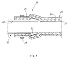
- FIG. 3 shows, likewise in a schematic sectional illustration, an exemplary embodiment of a pipeline connection 20 using a composite pipe 1 of the type shown in FIG. 1.
- a connector 21 with a connecting part 22 can be seen in the figure.
- This connector 21 can be made of any suitable material and the take a wide variety of forms, for example an angle tube, a T-piece or a tube end of another tube, also a composite tube 1 of the type shown in FIG. 1.
- the connecting part 22 is provided with an upstanding surface structure or an upstanding connecting element 23 which is designed such that it prevents the connected pipe end from sliding off after the connection has been made.
- the connecting element 23 forms a protruding projection which slopes steeply on one side and slopes away on the other side.
- the connecting element 23 can generally consist of a bead, bead, groove or knurling, which effectively prevents the connector 22 from sliding off.
- a pipe end 25 of a composite pipe 24 is pushed onto the connector part 22 on the outside; this tube end has been expanded, for example, by means of a conventional expanding mandrel to an inner diameter which is somewhat larger than the outer diameter of the connecting part 22.
- the composite tube 24 is constructed analogously to the composite tube 1 and consists of an outer tube 26 made of a metal which is corrosion-resistant under the conditions of use of the composite tube 24 and a thermoelastically stretched inner tube 27 made of a thermoelastic plastic and sealingly sealing the outer tube 26.
- a composite pipe 24 is connected to a T-shaped connecting piece 21 with three connecting parts 22 in accordance with the aforementioned type.
- T-shaped connecting piece 21 instead of the T-shaped connecting piece 21, other connecting pieces, for example angle pipes, can be used for this.
- Each connecting part 22 is provided with a plurality of connecting elements 23 which protrude from its circumference and are designed in such a way that they reliably prevent the connected pipe end 25 from sliding off after the connection has been made.
- the connecting elements 23 form annular members arranged axially at a distance on the circumference of the connecting part.
- the connecting elements 23 can also be designed in accordance with FIG. 3 with inclined surfaces and sloping edges or generally as a bead or bead, also as knurling, in such a way that sliding off the connecting part 22 is effectively prevented.
- the training can also be that at least one of the annular, upstanding connecting elements 23 is provided with knurling.
- the pipe end 25 of the composite pipe 24 is pushed onto the connecting part 22 via the connecting elements 23.
- this tube end 25 is expanded, for example by means of a conventional expanding mandrel, to an inner diameter which is somewhat larger than the outer diameter of the connecting part 22.
- the pipe end 25 pushed onto the connecting part 22 beyond the upstanding connecting elements 23 is pressed together with the connecting part 22 and is thereby held firmly thereon.
- This can be done with the help of the mechanically or hydraulically operated tools mentioned above, which cause deformation of the pipe end 25 and the connecting part 22 in the area of the attack, as a result of which a positive, secure connection is created between the two parts.
- the tendon 28 can be used, which engages around the pipe end 25 pushed on and is tightened.
- the exemplary embodiment shown additionally contains a securing ring 30 pushed onto the pipe end 25.
Applications Claiming Priority (4)
| Application Number | Priority Date | Filing Date | Title |
|---|---|---|---|
| DE19914130167 DE4130167A1 (de) | 1991-09-11 | 1991-09-11 | Verbundrohr und verfahren zu seiner herstellung und rohrleitungsverbindung aus dem verbundrohr |
| DE4130167 | 1991-09-11 | ||
| DE4217538A DE4217538A1 (de) | 1991-09-11 | 1992-05-27 | Rohrleitungsverbindung aus einem Verbundrohr |
| DE4217538 | 1992-05-27 |
Publications (3)
| Publication Number | Publication Date |
|---|---|
| EP0531790A2 true EP0531790A2 (fr) | 1993-03-17 |
| EP0531790A3 EP0531790A3 (en) | 1993-10-13 |
| EP0531790B1 EP0531790B1 (fr) | 1998-04-22 |
Family
ID=25907193
Family Applications (1)
| Application Number | Title | Priority Date | Filing Date |
|---|---|---|---|
| EP92114451A Expired - Lifetime EP0531790B1 (fr) | 1991-09-11 | 1992-08-25 | Raccord pour tuyau composite |
Country Status (5)
| Country | Link |
|---|---|
| EP (1) | EP0531790B1 (fr) |
| AT (1) | ATE165432T1 (fr) |
| DE (2) | DE4217538A1 (fr) |
| DK (1) | DK0531790T3 (fr) |
| ES (1) | ES2117021T3 (fr) |
Cited By (10)
| Publication number | Priority date | Publication date | Assignee | Title |
|---|---|---|---|---|
| DE29713049U1 (de) * | 1997-07-23 | 1997-09-18 | Unicor Rohrsysteme Gmbh | Verbundrohr |
| WO1998050725A1 (fr) * | 1997-05-03 | 1998-11-12 | Advanced Engineering Solutions Limited | Procede permettant de garnir des tuyaux |
| DE19731580A1 (de) * | 1997-07-23 | 1999-01-28 | Unicor Rohrsysteme Gmbh | Verbundrohr |
| EP1122009A1 (fr) * | 2000-02-07 | 2001-08-08 | Franz Viegener II GmbH & Co. KG. | Dispositif et procédé pour enlever la couche métallique à l'extrémité d'un tuyau multi-couche metal-plastique afin de faciliter la mise en place d'un raccord à compression |
| WO2009018721A1 (fr) * | 2007-08-09 | 2009-02-12 | Mingwei Zhang | Équipement et procédé de fabrication de conduite composite acier/plastique |
| EP2118550A2 (fr) * | 2007-01-22 | 2009-11-18 | John Frederick Olson | Tuyau revêtu d'élastomère, résistant à l'abrasion, et procédé de fabrication |
| GB2540422A (en) * | 2015-07-17 | 2017-01-18 | Rolls Royce Plc | Fluid conduit liner |
| CN107584742A (zh) * | 2017-07-28 | 2018-01-16 | 山西华星管业科技有限公司 | 超高分子量聚乙烯管材的生产方法及其使用的挤出机机模 |
| CN107654760A (zh) * | 2017-10-04 | 2018-02-02 | 英立(江苏)机电有限公司 | 一种具有阻燃功能的pe燃气管道 |
| CN107961741A (zh) * | 2014-05-26 | 2018-04-27 | 英尼奥斯欧洲股份公司 | 用于酸添加的进口喷嘴 |
Families Citing this family (5)
| Publication number | Priority date | Publication date | Assignee | Title |
|---|---|---|---|---|
| DE19536598C2 (de) * | 1995-09-19 | 2000-01-13 | Mannesmann Ag | Rohrverbindung |
| DE20104340U1 (de) * | 2001-03-14 | 2002-07-25 | Uponor Innovation Ab | Kunststoffrohr |
| PT103638B (pt) * | 2007-01-11 | 2007-06-06 | Duofil Sociedade Com E Ind De | Processo de montagem de uma união para condutas tubulares e respectiva união |
| CN102022588A (zh) * | 2010-08-27 | 2011-04-20 | 广东联塑科技实业有限公司 | 一种衬塑钢塑复合管及其制造方法 |
| CN107449153A (zh) * | 2017-08-18 | 2017-12-08 | 合肥荣电环境电器有限公司 | 一种家用热水器的内胆水管连接装置 |
Citations (9)
| Publication number | Priority date | Publication date | Assignee | Title |
|---|---|---|---|---|
| GB1124540A (en) * | 1965-10-11 | 1968-08-21 | Upjohn Co | Metal clad plastics piping |
| FR2191058A1 (fr) * | 1972-06-27 | 1974-02-01 | Btr Industries Ltd | |
| AU6548174A (en) * | 1973-02-09 | 1975-08-14 | Juralco Pty. Limited | Drawing thermoplastics tubing |
| DE2531785A1 (de) * | 1975-07-16 | 1977-01-20 | Teleflex Gmbh | Verfahren zur herstellung eines verbundrohres |
| EP0241297A2 (fr) * | 1986-04-11 | 1987-10-14 | Du Pont (UK) Limited | Fabrication d'un tuyau revêtu d'une matière polymère thermoplastique |
| EP0254489A2 (fr) * | 1986-07-24 | 1988-01-27 | BP Chemicals Limited | Procédé de revêtement intérieur de tubes |
| WO1991002918A1 (fr) * | 1989-08-22 | 1991-03-07 | British Gas Plc | Raccord de conduits |
| WO1992009840A1 (fr) * | 1990-11-30 | 1992-06-11 | Hewing Gmbh | Raccord de tuyaux, notamment de tuyaux d'assemblage |
| US5135698A (en) * | 1991-05-28 | 1992-08-04 | Conoco Inc. | Lining of pipelines using a continuous tubular pull-through plastic liner |
-
1992
- 1992-05-27 DE DE4217538A patent/DE4217538A1/de not_active Withdrawn
- 1992-08-25 DK DK92114451T patent/DK0531790T3/da active
- 1992-08-25 ES ES92114451T patent/ES2117021T3/es not_active Expired - Lifetime
- 1992-08-25 EP EP92114451A patent/EP0531790B1/fr not_active Expired - Lifetime
- 1992-08-25 DE DE59209296T patent/DE59209296D1/de not_active Expired - Fee Related
- 1992-08-25 AT AT92114451T patent/ATE165432T1/de not_active IP Right Cessation
Patent Citations (9)
| Publication number | Priority date | Publication date | Assignee | Title |
|---|---|---|---|---|
| GB1124540A (en) * | 1965-10-11 | 1968-08-21 | Upjohn Co | Metal clad plastics piping |
| FR2191058A1 (fr) * | 1972-06-27 | 1974-02-01 | Btr Industries Ltd | |
| AU6548174A (en) * | 1973-02-09 | 1975-08-14 | Juralco Pty. Limited | Drawing thermoplastics tubing |
| DE2531785A1 (de) * | 1975-07-16 | 1977-01-20 | Teleflex Gmbh | Verfahren zur herstellung eines verbundrohres |
| EP0241297A2 (fr) * | 1986-04-11 | 1987-10-14 | Du Pont (UK) Limited | Fabrication d'un tuyau revêtu d'une matière polymère thermoplastique |
| EP0254489A2 (fr) * | 1986-07-24 | 1988-01-27 | BP Chemicals Limited | Procédé de revêtement intérieur de tubes |
| WO1991002918A1 (fr) * | 1989-08-22 | 1991-03-07 | British Gas Plc | Raccord de conduits |
| WO1992009840A1 (fr) * | 1990-11-30 | 1992-06-11 | Hewing Gmbh | Raccord de tuyaux, notamment de tuyaux d'assemblage |
| US5135698A (en) * | 1991-05-28 | 1992-08-04 | Conoco Inc. | Lining of pipelines using a continuous tubular pull-through plastic liner |
Cited By (14)
| Publication number | Priority date | Publication date | Assignee | Title |
|---|---|---|---|---|
| WO1998050725A1 (fr) * | 1997-05-03 | 1998-11-12 | Advanced Engineering Solutions Limited | Procede permettant de garnir des tuyaux |
| AU741595B2 (en) * | 1997-05-03 | 2001-12-06 | Advanced Engineering Solutions Limited | Method of lining pipes |
| DE29713049U1 (de) * | 1997-07-23 | 1997-09-18 | Unicor Rohrsysteme Gmbh | Verbundrohr |
| DE19731580A1 (de) * | 1997-07-23 | 1999-01-28 | Unicor Rohrsysteme Gmbh | Verbundrohr |
| EP1122009A1 (fr) * | 2000-02-07 | 2001-08-08 | Franz Viegener II GmbH & Co. KG. | Dispositif et procédé pour enlever la couche métallique à l'extrémité d'un tuyau multi-couche metal-plastique afin de faciliter la mise en place d'un raccord à compression |
| EP2118550A2 (fr) * | 2007-01-22 | 2009-11-18 | John Frederick Olson | Tuyau revêtu d'élastomère, résistant à l'abrasion, et procédé de fabrication |
| EP2118550A4 (fr) * | 2007-01-22 | 2010-12-08 | John Frederick Olson | Tuyau revêtu d'élastomère, résistant à l'abrasion, et procédé de fabrication |
| WO2009018721A1 (fr) * | 2007-08-09 | 2009-02-12 | Mingwei Zhang | Équipement et procédé de fabrication de conduite composite acier/plastique |
| US8146639B2 (en) | 2007-08-09 | 2012-04-03 | Mingwei Zhang | Equipment and method for manufacturing steel-plastic composite pipe |
| CN107961741A (zh) * | 2014-05-26 | 2018-04-27 | 英尼奥斯欧洲股份公司 | 用于酸添加的进口喷嘴 |
| GB2540422A (en) * | 2015-07-17 | 2017-01-18 | Rolls Royce Plc | Fluid conduit liner |
| CN107584742A (zh) * | 2017-07-28 | 2018-01-16 | 山西华星管业科技有限公司 | 超高分子量聚乙烯管材的生产方法及其使用的挤出机机模 |
| CN107584742B (zh) * | 2017-07-28 | 2019-05-17 | 山西华星管业科技有限公司 | 超高分子量聚乙烯管材的生产方法及其使用的挤出机机模 |
| CN107654760A (zh) * | 2017-10-04 | 2018-02-02 | 英立(江苏)机电有限公司 | 一种具有阻燃功能的pe燃气管道 |
Also Published As
| Publication number | Publication date |
|---|---|
| ATE165432T1 (de) | 1998-05-15 |
| DE4217538A1 (de) | 1993-12-02 |
| ES2117021T3 (es) | 1998-08-01 |
| DK0531790T3 (da) | 1999-01-18 |
| DE59209296D1 (de) | 1998-05-28 |
| EP0531790B1 (fr) | 1998-04-22 |
| EP0531790A3 (en) | 1993-10-13 |
Similar Documents
| Publication | Publication Date | Title |
|---|---|---|
| DE69927489T3 (de) | Mehrschichtiges kunststoffrohr und seine verwendung | |
| EP0531790A2 (fr) | Tuyau composite, procédé pour sa fabrication et la connexion dudit tuyau | |
| DE19707827C2 (de) | Pressverbindung | |
| EP0057000A1 (fr) | Procédé pour déformer des objets en matière plastique | |
| EP0530387B2 (fr) | Raccord pour tuyauterie et méthode de fabrication de raccords pour tuyauteries en polyoléfine | |
| DE3817442C2 (de) | Schellenlose Rohrleitungsverbindung | |
| DE4130167A1 (de) | Verbundrohr und verfahren zu seiner herstellung und rohrleitungsverbindung aus dem verbundrohr | |
| DE102006057199A1 (de) | Verbundrohr mit zwei Polyvinylidenflurid-Schichten | |
| WO2011128051A1 (fr) | Système de tuyaux pour installation intérieure et son utilisation | |
| EP3110567B1 (fr) | Ensemble de gros tuyaux et procédé de production d'un ensemble de gros tuyaux de ce type | |
| EP0102919A2 (fr) | Procédé pour le raccordement de tuyaux et le raccord correspondant | |
| DE102008038039B4 (de) | Mehrschicht-Verbundrohr mit einer Polyvinylidenfluorid-Innenschicht | |
| DE19953737C1 (de) | Mehrschichtverbundrohr | |
| DE19911705C1 (de) | Verfahren zur Verbindung eines Rohres aus PE-X und eines Rohrformstücks aus PE durch Heizelement-Muffenschweißen, Vorrichtung zur Durchführung des Verfahrens und nach dem Verfahren hergestellte Verbindung | |
| DE202017006479U1 (de) | Rohrverbindung | |
| DE3342023A1 (de) | Verfahren zur hersellung eines kunststoffrohres mit permeationssperre | |
| DE7619362U1 (de) | Rohrkupplung | |
| EP0472056B1 (fr) | Element de raccord pour tuyaux | |
| EP1361038B1 (fr) | Méthode et procédé pour produire un tube composite | |
| DE102011114168B4 (de) | Verbundrohr mit einer profilierten Innenschicht | |
| DE4025840C2 (de) | Verfahren zur Herstellung von Rohrleitungsverbindungen aus Polyolefin | |
| DE3921174C2 (fr) | ||
| EP0183930B1 (fr) | Méthode de fabrication pour un tuyau métallique avec une couche protectrice contre la corrosion et les chocs | |
| AT520174B1 (de) | Rohrsanierungsverfahren zur Sanierung von unterirdisch oder oberirdisch verlegten, unbegehbaren oder begehbaren Rohrleitungen | |
| DE3152022C2 (fr) |
Legal Events
| Date | Code | Title | Description |
|---|---|---|---|
| PUAI | Public reference made under article 153(3) epc to a published international application that has entered the european phase |
Free format text: ORIGINAL CODE: 0009012 |
|
| AK | Designated contracting states |
Kind code of ref document: A2 Designated state(s): AT BE CH DE DK ES FR GB GR IT LI LU NL PT SE |
|
| PUAL | Search report despatched |
Free format text: ORIGINAL CODE: 0009013 |
|
| AK | Designated contracting states |
Kind code of ref document: A3 Designated state(s): AT BE CH DE DK ES FR GB GR IT LI LU NL PT SE |
|
| 17P | Request for examination filed |
Effective date: 19940317 |
|
| 17Q | First examination report despatched |
Effective date: 19950908 |
|
| GRAG | Despatch of communication of intention to grant |
Free format text: ORIGINAL CODE: EPIDOS AGRA |
|
| GRAG | Despatch of communication of intention to grant |
Free format text: ORIGINAL CODE: EPIDOS AGRA |
|
| GRAH | Despatch of communication of intention to grant a patent |
Free format text: ORIGINAL CODE: EPIDOS IGRA |
|
| GRAH | Despatch of communication of intention to grant a patent |
Free format text: ORIGINAL CODE: EPIDOS IGRA |
|
| GRAA | (expected) grant |
Free format text: ORIGINAL CODE: 0009210 |
|
| AK | Designated contracting states |
Kind code of ref document: B1 Designated state(s): AT BE CH DE DK ES FR GB GR IT LI LU NL PT SE |
|
| REF | Corresponds to: |
Ref document number: 165432 Country of ref document: AT Date of ref document: 19980515 Kind code of ref document: T |
|
| REG | Reference to a national code |
Ref country code: CH Ref legal event code: EP |
|
| REF | Corresponds to: |
Ref document number: 59209296 Country of ref document: DE Date of ref document: 19980528 |
|
| ET | Fr: translation filed | ||
| REG | Reference to a national code |
Ref country code: CH Ref legal event code: NV Representative=s name: TROESCH SCHEIDEGGER WERNER AG |
|
| ITF | It: translation for a ep patent filed |
Owner name: STUDIO JAUMANN P. & C. S.N.C. |
|
| PGFP | Annual fee paid to national office [announced via postgrant information from national office to epo] |
Ref country code: GB Payment date: 19980714 Year of fee payment: 7 |
|
| PGFP | Annual fee paid to national office [announced via postgrant information from national office to epo] |
Ref country code: FR Payment date: 19980716 Year of fee payment: 7 |
|
| PGFP | Annual fee paid to national office [announced via postgrant information from national office to epo] |
Ref country code: BE Payment date: 19980717 Year of fee payment: 7 |
|
| PGFP | Annual fee paid to national office [announced via postgrant information from national office to epo] |
Ref country code: PT Payment date: 19980720 Year of fee payment: 7 |
|
| PGFP | Annual fee paid to national office [announced via postgrant information from national office to epo] |
Ref country code: LU Payment date: 19980729 Year of fee payment: 7 Ref country code: GR Payment date: 19980729 Year of fee payment: 7 |
|
| REG | Reference to a national code |
Ref country code: ES Ref legal event code: FG2A Ref document number: 2117021 Country of ref document: ES Kind code of ref document: T3 |
|
| PGFP | Annual fee paid to national office [announced via postgrant information from national office to epo] |
Ref country code: ES Payment date: 19980803 Year of fee payment: 7 |
|
| GBT | Gb: translation of ep patent filed (gb section 77(6)(a)/1977) |
Effective date: 19980721 |
|
| PGFP | Annual fee paid to national office [announced via postgrant information from national office to epo] |
Ref country code: AT Payment date: 19980814 Year of fee payment: 7 |
|
| PGFP | Annual fee paid to national office [announced via postgrant information from national office to epo] |
Ref country code: NL Payment date: 19980831 Year of fee payment: 7 |
|
| REG | Reference to a national code |
Ref country code: PT Ref legal event code: SC4A Free format text: AVAILABILITY OF NATIONAL TRANSLATION Effective date: 19980622 |
|
| PGFP | Annual fee paid to national office [announced via postgrant information from national office to epo] |
Ref country code: CH Payment date: 19981102 Year of fee payment: 7 |
|
| REG | Reference to a national code |
Ref country code: DK Ref legal event code: T3 |
|
| PLBE | No opposition filed within time limit |
Free format text: ORIGINAL CODE: 0009261 |
|
| STAA | Information on the status of an ep patent application or granted ep patent |
Free format text: STATUS: NO OPPOSITION FILED WITHIN TIME LIMIT |
|
| 26N | No opposition filed | ||
| PG25 | Lapsed in a contracting state [announced via postgrant information from national office to epo] |
Ref country code: LU Free format text: LAPSE BECAUSE OF NON-PAYMENT OF DUE FEES Effective date: 19990825 Ref country code: GB Free format text: LAPSE BECAUSE OF NON-PAYMENT OF DUE FEES Effective date: 19990825 Ref country code: AT Free format text: LAPSE BECAUSE OF NON-PAYMENT OF DUE FEES Effective date: 19990825 |
|
| PG25 | Lapsed in a contracting state [announced via postgrant information from national office to epo] |
Ref country code: ES Free format text: LAPSE BECAUSE OF NON-PAYMENT OF DUE FEES Effective date: 19990826 |
|
| PG25 | Lapsed in a contracting state [announced via postgrant information from national office to epo] |
Ref country code: LI Free format text: LAPSE BECAUSE OF NON-PAYMENT OF DUE FEES Effective date: 19990831 Ref country code: GR Free format text: LAPSE BECAUSE OF NON-PAYMENT OF DUE FEES Effective date: 19990831 Ref country code: CH Free format text: LAPSE BECAUSE OF NON-PAYMENT OF DUE FEES Effective date: 19990831 Ref country code: BE Free format text: LAPSE BECAUSE OF NON-PAYMENT OF DUE FEES Effective date: 19990831 |
|
| BERE | Be: lapsed |
Owner name: WIRSBO ROHRPRODUKTION UND VERTRIEBS-G.M.B.H. Effective date: 19990831 |
|
| PG25 | Lapsed in a contracting state [announced via postgrant information from national office to epo] |
Ref country code: PT Free format text: LAPSE BECAUSE OF NON-PAYMENT OF DUE FEES Effective date: 20000229 |
|
| PG25 | Lapsed in a contracting state [announced via postgrant information from national office to epo] |
Ref country code: NL Free format text: LAPSE BECAUSE OF NON-PAYMENT OF DUE FEES Effective date: 20000301 |
|
| REG | Reference to a national code |
Ref country code: CH Ref legal event code: PL |
|
| GBPC | Gb: european patent ceased through non-payment of renewal fee |
Effective date: 19990825 |
|
| PG25 | Lapsed in a contracting state [announced via postgrant information from national office to epo] |
Ref country code: FR Free format text: LAPSE BECAUSE OF NON-PAYMENT OF DUE FEES Effective date: 20000428 |
|
| NLV4 | Nl: lapsed or anulled due to non-payment of the annual fee |
Effective date: 20000301 |
|
| REG | Reference to a national code |
Ref country code: PT Ref legal event code: MM4A Free format text: LAPSE DUE TO NON-PAYMENT OF FEES Effective date: 20000229 |
|
| REG | Reference to a national code |
Ref country code: FR Ref legal event code: ST |
|
| PGFP | Annual fee paid to national office [announced via postgrant information from national office to epo] |
Ref country code: SE Payment date: 20010810 Year of fee payment: 10 |
|
| PGFP | Annual fee paid to national office [announced via postgrant information from national office to epo] |
Ref country code: DK Payment date: 20010816 Year of fee payment: 10 |
|
| PGFP | Annual fee paid to national office [announced via postgrant information from national office to epo] |
Ref country code: DE Payment date: 20011020 Year of fee payment: 10 |
|
| PG25 | Lapsed in a contracting state [announced via postgrant information from national office to epo] |
Ref country code: SE Free format text: LAPSE BECAUSE OF NON-PAYMENT OF DUE FEES Effective date: 20020826 |
|
| PG25 | Lapsed in a contracting state [announced via postgrant information from national office to epo] |
Ref country code: DK Free format text: LAPSE BECAUSE OF NON-PAYMENT OF DUE FEES Effective date: 20020930 |
|
| PG25 | Lapsed in a contracting state [announced via postgrant information from national office to epo] |
Ref country code: DE Free format text: LAPSE BECAUSE OF NON-PAYMENT OF DUE FEES Effective date: 20030301 |
|
| REG | Reference to a national code |
Ref country code: DK Ref legal event code: EBP |
|
| EUG | Se: european patent has lapsed | ||
| REG | Reference to a national code |
Ref country code: ES Ref legal event code: FD2A Effective date: 20000911 |
|
| PG25 | Lapsed in a contracting state [announced via postgrant information from national office to epo] |
Ref country code: IT Free format text: LAPSE BECAUSE OF NON-PAYMENT OF DUE FEES;WARNING: LAPSES OF ITALIAN PATENTS WITH EFFECTIVE DATE BEFORE 2007 MAY HAVE OCCURRED AT ANY TIME BEFORE 2007. THE CORRECT EFFECTIVE DATE MAY BE DIFFERENT FROM THE ONE RECORDED. Effective date: 20050825 |