EP2060883A1 - Füllstandsensor für kurze Messentfernungen - Google Patents
Füllstandsensor für kurze Messentfernungen Download PDFInfo
- Publication number
- EP2060883A1 EP2060883A1 EP07120998A EP07120998A EP2060883A1 EP 2060883 A1 EP2060883 A1 EP 2060883A1 EP 07120998 A EP07120998 A EP 07120998A EP 07120998 A EP07120998 A EP 07120998A EP 2060883 A1 EP2060883 A1 EP 2060883A1
- Authority
- EP
- European Patent Office
- Prior art keywords
- antenna
- level sensor
- sensor according
- antennas
- antenna system
- Prior art date
- Legal status (The legal status is an assumption and is not a legal conclusion. Google has not performed a legal analysis and makes no representation as to the accuracy of the status listed.)
- Granted
Links
- 239000000446 fuel Substances 0.000 title 1
- 230000005540 biological transmission Effects 0.000 claims abstract description 9
- 238000005259 measurement Methods 0.000 claims description 18
- 238000009434 installation Methods 0.000 abstract 1
- 230000010287 polarization Effects 0.000 description 12
- 230000008878 coupling Effects 0.000 description 4
- 238000010168 coupling process Methods 0.000 description 4
- 238000005859 coupling reaction Methods 0.000 description 4
- 238000013461 design Methods 0.000 description 4
- 230000035945 sensitivity Effects 0.000 description 4
- 230000005684 electric field Effects 0.000 description 3
- 239000004033 plastic Substances 0.000 description 3
- 238000002592 echocardiography Methods 0.000 description 2
- 230000002452 interceptive effect Effects 0.000 description 2
- 238000002955 isolation Methods 0.000 description 2
- 229940058401 polytetrafluoroethylene Drugs 0.000 description 2
- 239000004810 polytetrafluoroethylene Substances 0.000 description 2
- 230000002411 adverse Effects 0.000 description 1
- 230000000052 comparative effect Effects 0.000 description 1
- 230000001419 dependent effect Effects 0.000 description 1
- 238000011161 development Methods 0.000 description 1
- 230000018109 developmental process Effects 0.000 description 1
- 238000002474 experimental method Methods 0.000 description 1
- 238000001746 injection moulding Methods 0.000 description 1
- 230000010354 integration Effects 0.000 description 1
- 238000001465 metallisation Methods 0.000 description 1
- 238000000034 method Methods 0.000 description 1
- 239000000243 solution Substances 0.000 description 1
- 239000000126 substance Substances 0.000 description 1
- 239000000758 substrate Substances 0.000 description 1
- 238000012549 training Methods 0.000 description 1
- 210000002700 urine Anatomy 0.000 description 1
Images


Classifications
-
- G—PHYSICS
- G01—MEASURING; TESTING
- G01F—MEASURING VOLUME, VOLUME FLOW, MASS FLOW OR LIQUID LEVEL; METERING BY VOLUME
- G01F23/00—Indicating or measuring liquid level or level of fluent solid material, e.g. indicating in terms of volume or indicating by means of an alarm
- G01F23/22—Indicating or measuring liquid level or level of fluent solid material, e.g. indicating in terms of volume or indicating by means of an alarm by measuring physical variables, other than linear dimensions, pressure or weight, dependent on the level to be measured, e.g. by difference of heat transfer of steam or water
- G01F23/28—Indicating or measuring liquid level or level of fluent solid material, e.g. indicating in terms of volume or indicating by means of an alarm by measuring physical variables, other than linear dimensions, pressure or weight, dependent on the level to be measured, e.g. by difference of heat transfer of steam or water by measuring the variations of parameters of electromagnetic or acoustic waves applied directly to the liquid or fluent solid material
- G01F23/284—Electromagnetic waves
-
- G—PHYSICS
- G01—MEASURING; TESTING
- G01S—RADIO DIRECTION-FINDING; RADIO NAVIGATION; DETERMINING DISTANCE OR VELOCITY BY USE OF RADIO WAVES; LOCATING OR PRESENCE-DETECTING BY USE OF THE REFLECTION OR RERADIATION OF RADIO WAVES; ANALOGOUS ARRANGEMENTS USING OTHER WAVES
- G01S13/00—Systems using the reflection or reradiation of radio waves, e.g. radar systems; Analogous systems using reflection or reradiation of waves whose nature or wavelength is irrelevant or unspecified
- G01S13/88—Radar or analogous systems specially adapted for specific applications
-
- G—PHYSICS
- G01—MEASURING; TESTING
- G01S—RADIO DIRECTION-FINDING; RADIO NAVIGATION; DETERMINING DISTANCE OR VELOCITY BY USE OF RADIO WAVES; LOCATING OR PRESENCE-DETECTING BY USE OF THE REFLECTION OR RERADIATION OF RADIO WAVES; ANALOGOUS ARRANGEMENTS USING OTHER WAVES
- G01S7/00—Details of systems according to groups G01S13/00, G01S15/00, G01S17/00
- G01S7/02—Details of systems according to groups G01S13/00, G01S15/00, G01S17/00 of systems according to group G01S13/00
- G01S7/03—Details of HF subsystems specially adapted therefor, e.g. common to transmitter and receiver
-
- H—ELECTRICITY
- H01—ELECTRIC ELEMENTS
- H01Q—ANTENNAS, i.e. RADIO AERIALS
- H01Q1/00—Details of, or arrangements associated with, antennas
- H01Q1/12—Supports; Mounting means
- H01Q1/22—Supports; Mounting means by structural association with other equipment or articles
- H01Q1/225—Supports; Mounting means by structural association with other equipment or articles used in level-measurement devices, e.g. for level gauge measurement
-
- H—ELECTRICITY
- H01—ELECTRIC ELEMENTS
- H01Q—ANTENNAS, i.e. RADIO AERIALS
- H01Q1/00—Details of, or arrangements associated with, antennas
- H01Q1/42—Housings not intimately mechanically associated with radiating elements, e.g. radome
-
- H—ELECTRICITY
- H01—ELECTRIC ELEMENTS
- H01Q—ANTENNAS, i.e. RADIO AERIALS
- H01Q13/00—Waveguide horns or mouths; Slot antennas; Leaky-waveguide antennas; Equivalent structures causing radiation along the transmission path of a guided wave
- H01Q13/02—Waveguide horns
Definitions
- the present invention relates to the level measurement.
- the present invention relates to a level sensor for short range measurements, an antenna system for a level sensor, the use of a level sensor for level measurement and the use of an antenna system for level measurement.
- Known radar sensors for level measurement have a common antenna for transmitter and receiver.
- CGS the antenna coupling between the high-frequency module and the antenna KK: CGS: ag a so-called.
- Dead zone arise in which on the one hand, the sensitivity is significantly reduced and on the other hand, the measurement accuracy is greatly reduced by interfering with the reflections of the antenna system with the reflections of the product surface.
- a filling level sensor for short distance measurements which has a first antenna for transmitting a transmission signal to a product surface, a second antenna for receiving a reception signal reflected from the product surface and a common outer casing for the first and the second antenna.
- Such a level sensor is particularly well suited for accurate measurements in the near range due to a significantly reduced “dead zone” and can therefore also be used in small containers.
- the common outer shell is designed as a housing, which is designed to receive the first and second antenna.
- the common outer shell can be made of a plastic, for example.
- PTFE poly-tetra-fluoro-ethylene
- the common outer shell or the housing has a round, elliptical or angular base.
- the base of the common outer shell or the housing is adapted to the opening cross-section of the two antennas. If, for example, the two antennas each have a semicircular opening cross-section, then the base surface of the outer shell can be circular or, for example, also elliptical.
- a large opening cross-section of the antennas means a higher bundling (smaller opening angle) and a higher antenna gain.
- the first and second antenna each have a round, elliptical or angular opening cross-section.
- the common outer shell has a cylindrical or conical outer shape.
- the first and second antennas are designed as horn antennas.
- the horn antennas have the advantage of good electrical properties, e.g. a large area efficiency compared to other antenna types. This area efficiency is usually at least 60%.
- the first and second antenna each have an antenna horn with a semicircular or semi-elliptical cross section.
- the base of the outer shell can be optimally utilized and a minimum opening angle and a maximum antenna gain of the antennas can be achieved.
- the level sensor is designed as a level radar sensor.
- an antenna system for a short range level sensor comprising a first antenna for transmitting a transmit signal to a product surface, a second antenna for receiving a receive signal reflected from the product surface, and a common outer can for the first and second antenna.
- the described embodiments relate equally to the antenna system, the level sensor and the use of the antenna system and the level sensor for level measurement.
- the antenna system is made in one piece. In this way, the stability of the antenna system can be increased.
- the first and second antenna each have an antenna horn with a semicircular or semi-elliptical cross section.
- the level sensor further comprises a front antenna cover with an inwardly directed curvature.
- the curvature of the antenna cover is designed conical.
- the antenna system is designed for flush mounting in a flange.
- the cover of the antenna is e.g. Curved inward in a conical shape and provided with a drip edge at the outer edge where condensate can collect and drain off.
- Fig. 1 shows a radar sensor with separate planar antennas for transmitter and receiver.
- Fig. 2 shows a schematic representation of two horn antennas according to an embodiment of the present invention.
- FIGS. 3A and 3B show an antenna system with mutually inclined horn antennas according to another embodiment of the present invention.
- FIGS. 4A and 4B show antenna systems with two half horn antennas according to another embodiment of the present invention.
- Fig. 5 shows an antenna system with two half horn antennas, which are arranged directly next to each other, according to another embodiment of the present invention.
- Fig. 6 shows an antenna system with two curved horn antennas according to another embodiment of the present invention.
- Fig. 7 shows a schematic cross-sectional view of an antenna system with two half horn antennas according to another embodiment of the present invention.
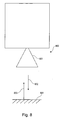
- Fig. 8 shows a level gauge or level sensor according to another embodiment of the present invention.
- Fig. 9 shows a schematic representation of polarization planes of the transmit and receive signals according to an embodiment of the present invention.
- Fig. 10 shows a schematic representation of polarization planes of the transmit and receive signals according to another embodiment of the present invention.
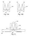
- FIGS. 11A and 11B show an antenna system with inwardly curved cover 1101 of the antennas according to another embodiment of the present invention.
- Fig. 12 shows an antenna system with flush mounting according to another embodiment of the present invention.
- Fig. 1 shows a radar sensor with separate planar antennas 102, 103 for transmitter and receiver.
- the planar antennas 102, 103 are arranged on a printed circuit board 101.
- an electronics module 104 is provided.
- the process temperature is significantly limited because the electronic components are exposed to the full temperature of the container.
- Fig. 2 shows an antenna system with a first horn antenna 201 and a second urine antenna 202, which are arranged side by side in a common housing 203.
- the cross-sectional areas of the antenna horns are here, for example, round or elliptical.
- Fig. 3A shows an antenna system according to another embodiment of the present invention, in which the "normal" horn antennas 201, 202 are arranged inclined to each other.
- the container has, for example, a cylindrical shape whose cross section is adapted to the opening cross sections of the antennas 201, 202.
- Fig. 3B shows a further embodiment of an antenna system in which the two horn antennas 201, 202 are also arranged inclined to each other.
- the common housing 203 is adapted to the inclination of the antennas, that is, for example, converges conically upwards.
- Fig. 4A shows another embodiment of an antenna system according to the present invention, in which two "half" horn antennas 201, 202 are arranged side by side in the housing 203.
- the housing is designed, for example, cylindrical.
- Fig. 4B shows a further embodiment of the present invention, in which the two "half" horn antennas 201, 202 are also arranged side by side and also as in the embodiment of Fig. 4A have a semicircular or semi-elliptical cross section.
- the housing 203 converges upward and is adapted, for example, to the outer shape of the horn antennas 201, 202 by having a circular or elliptical cross section.
- Fig. 5 shows a further embodiment of an antenna system according to another embodiment of the present invention, in which the two horn antennas 201, 202 are arranged directly adjacent to each other, so that they have a common outer shape as in a training normal horn antenna.
- the two horn antennas 201, 202 are designed, for example, with a semicircular or semi-elliptical cross section ("half" horn antennas).
- Fig. 6 shows an antenna system according to another embodiment of the present invention, in which the two horn antennas 201, 202 are executed bent.
- Fig. 7 shows an antenna system according to another embodiment of the present invention, in a view from below, so on the openings of the horn antennas 201, 202.
- the two horn antennas are arranged side by side, twisted to each other.
- the common housing 203 has, for example, an elliptical cross section.
- Figs. 11A and 11B show an antenna system with inwardly curved cover 1101 of the antennas. This design allows condensate, which collects on the front cover to drain to the edge and drain there.
- the curvature 1101 may, for example, be conical or round.
- the inwardly domed cover has the advantage of much higher decoupling (about 15dB better) of the two antennas over the outward bulge (e.g., drip tip in the middle).
- FIG. 12 shows an antenna system with flush mounting.
- the common housing consists of a flange 1201, a plastic cover 1202 and a surrounding housing 1203.
- the connecting piece 1204 forms the connection to the electronics housing (not shown).
- This version is particularly suitable for small containers without nozzles, because the sensor does not protrude into the container and thereby additionally reduces the possible measuring range.
- the two horn antennas are arranged together in a cylindrical, elliptical or conical housing, for example, side by side.
- a preferred solution is the conical antenna housing, since here the diameter at the antenna front edge tapers towards the antenna connection and can thus easily be connected to existing electronics housings.
- the two antennas can have a round, semicircular, elliptical or angular opening cross-section, so that they optimally utilize the area of the antenna housing facing the medium. As a result, the maximum possible antenna gain and the minimum opening angle can be achieved for a given area.
- Advantages are in particular a good decoupling between transmitting and receiving antenna, a compact design of the antenna system, a small "dead zone” and thus good accuracy and sensitivity in the vicinity and a very good suitability for small containers.
- Fig. 9 shows a schematic representation of polarization planes of the transmit and receive signals according to an embodiment of the present invention.
- Reference numerals 901 and 902 show the polarization planes of the electric field of the transmission signal (transmission antenna 201) and the reception signal (reception antenna 202), respectively.
- Fig. 10 shows a schematic representation of polarization planes of the transmit and receive signals according to another embodiment of the present invention.
- Reference numerals 1001 and 1002 show the polarization planes of the electric field of the transmission signal and the reception signal, respectively.
- the polarization planes of the electric field that is to say the transmitting and the receiving polarization
- the transmitting and the receiving polarization can be suitably aligned with one another.
- a parallel alignment of the transmitting and receiving polarization is advantageous.
- the antennae for transmitters and receivers have the same polarization planes.
- the polarization planes 901, 902 lie in a common plane.
- the polarization planes 1001, 1002 lie in separate, parallel planes, which are perpendicular to a connecting line between the centers of the antennas 201, 202.
- Fig. 10 leads to an improved isolation between transmitting and receiving antenna and thus also has low interfering signals (direct coupling over from the transmitter to the receiver) in the near range. This increases the measuring sensitivity in this area.
- the decoupling of the two antennas increases as the distance between the antennas increases. As a result, the coupling between the antennas and thus the ringing is greatly reduced.
- two different antenna variants round horn, half round horn
- the transmission behavior ie the isolation between transmitter and receiver
- Fig. 8 shows a schematic representation of a level radar according to another embodiment of the present invention.
- the fill level radar 800 in this case has a signal generator unit and a receiver circuit. Furthermore, an antenna device 801 (antenna system) according to an embodiment of the present invention is provided.
- the antenna system 801 transmits a transmission signal 802 in the direction of the product surface 804, which is reflected as a received signal 803 from the product surface and detected by the antenna system 801. From this then the level can be determined.
Abstract
Description
- Die vorliegende Erfindung betrifft die Füllstandsmessung. Insbesondere betrifft die vorliegende Erfindung einen Füllstandsensor für kurze Entfernungsmessungen, ein Antennensystem für einen Füllstandsensor, die Verwendung eines Füllstandsensors zur Füllstandsmessung und die Verwendung eines Antennensystems zur Füllstandsmessung.
- Bisherige Füllstandsmessgeräte haben aufgrund ihres Aufbaus bei kurzen Entfernungen zur Füllgutoberfläche (bis ca. 1,5 m) eine schlechtere Genauigkeit als bei Entfernungen von über 2 m zur Füllgutoberfläche. Diese Ungenauigkeiten können beispielsweise durch das sog. Antennenklingeln entstehen, das aus Mehrfachreflexionen zwischen dem Hochfrequenzmodul, der Antenneneinkopplung und dem Antennenrand besteht. Diese Reflexionen ragen bis in den Messbereich des Sensors hinein und verursachen dort einerseits Interferenzen mit einer Reflexion bzw. einem Echo einer Füllgutoberfläche oder sie reduzieren sogar die Messempfindlichkeit für kleine Reflexionen von der Füllgutoberfläche.
- Man spricht hier auch von einem "Totbereich", in dem der Sensor Echos nicht oder nur sehr schwer erkennen kann.
- Bekannte Radarsensoren zur Füllstandsmessung weisen eine gemeinsame Antenne für Sender und Empfänger auf. Bei solchen Sensoren kann durch eine endliche Reflexionsdämpfung der Antenne bzw. der Antenneneinkopplung zwischen dem Hochfrequenzmodul und der Antenne KK:CGS:ag
ein sog. Totbereich entstehen, in dem zum einen die Empfindlichkeit deutlich reduziert ist und zum anderen durch Interferenzen der Reflexionen des Antennensystems mit den Reflexionen der Füllgutoberfläche die Messgenauigkeit stark reduziert wird. - Es ist eine Aufgabe der vorliegenden Erfindung, eine verbesserte Messqualität im Nahbereich eines Füllstandsensors bereitzustellen.
- Es sind ein Füllstandsensor für kurze Entfernungsmessungen, ein Antennensystem für einen Füllstandsensor, die Verwendung eines Füllstandsensors zur Füllstandsmessung sowie die Verwendung eines Antennensystems zur Füllstandsmessung gemäß den Merkmalen der unabhängigen Ansprüche angegeben. Weiterbildungen der Erfindung ergeben sich aus den Unteransprüchen.
- Gemäß einem Ausführungsbeispiel der vorliegenden Erfindung ist ein Füllstandsensor für kurze Entfernungsmessungen angegeben, welcher eine erste Antenne zum Senden eines Sendesignals zu einer Füllgutoberfläche, eine zweite Antenne zum Empfangen eines von der Füllgutoberfläche reflektierten Empfangssignals und eine gemeinsame Außenhülle für die erste und die zweite Antenne aufweist.
- Ein solcher Füllstandsensor eignet sich durch einen deutlich reduzierten "Totbereich" besonders gut für genaue Messungen im Nahbereich und ist somit auch in kleinen Behältern einsetzbar.
- Durch die Integration zweier Antennen in eine gemeinsame "Außenhülle" oder in ein gemeinsames Gehäuse oder durch zwei Antennen mit einer gemeinsamen Außenkontur ergibt sich ein kompakter Aufbau, der auch noch durch kleine Behälteröffnungen hindurchpasst.
- Gemäß einem weiteren Ausführungsbeispiel der vorliegenden Erfindung ist die gemeinsame Außenhülle als ein Gehäuse ausgeführt, welches zur Aufnahme der ersten und zweiten Antenne ausgeführt ist.
- Auf diese Weise kann die Stabilität des Antennensystems des Sensors erhöht werden.
- Die gemeinsame Außenhülle kann zum Beispiel aus einen Kunststoff hergestellt werden. Im Falle von PTFE (Poly-Tetra-Fluor-Ethylen) erhält man damit eine sehr hohe chemische Beständigkeit.
- Gemäß einem weiteren Ausführungsbeispiel der vorliegenden Erfindung weist die gemeinsame Außenhülle bzw. das Gehäuse eine runde, elliptische oder eckige Grundfläche auf.
- Beispielsweise ist die Grundfläche der gemeinsamen Außenhülle oder des Gehäuses an den Öffnungsquerschnitt der beiden Antennen angepasst. Weisen beispielsweise die beiden Antennen jeweils einen halbrunden Öffnungsquerschnitt auf, so kann die Grundfläche der Außenhülle kreisrund oder beispielsweise auch elliptisch ausgestaltet sein.
- Durch den halbrunden Öffnungsquerschnitt der beiden Antennen wird die Grundfläche der Außenhülle optimal ausgenutzt. Eine großer Öffnungsquerschnitt der Antennen bedeutet eine höhere Bündelung (kleinerer Öffnungswinkel) und einen höheren Antennengewinn.
- Gemäß einem weiteren Ausführungsbeispiel der vorliegenden Erfindung weisen die erste und zweite Antenne jeweils einen runden, elliptischen oder eckigen Öffnungsquerschnitt auf.
- Weiterhin weist, gemäß einem weiteren Ausführungsbeispiel der vorliegenden Erfindung, die gemeinsame Außenhülle eine zylindrische oder kegelförmige Außenform auf.
- Gemäß einem weiteren Ausführungsbeispiel der vorliegenden Erfindung sind die ersten und zweiten Antennen als Hornantennen ausgeführt.
- Die Hornantennen haben den Vorteil guter elektrischer Eigenschaften, wie z.B. einem großen Flächenwirkungsgrad gegenüber anderer Antennentypen. Dieser Flächenwirkungsgrad leigt üblicherweise bei mindestens 60%.
- Gemäß einem weiteren Ausführungsbeispiel weisen die erste und zweite Antenne jeweils ein Antennenhorn mit halbkreisförmigem oder halbelliptischem Querschnitt auf. Damit können die Grundfläche der Außenhülle optimal ausgenutzt und ein minimaler Öffnungswinkel bzw. ein maximaler Antennengewinn der Antennen erzielt werden.
- Gemäß einem weiteren Ausführungsbeispiel der vorliegenden Erfindung ist der Füllstandsensor als Füllstandsradarsensor ausgeführt.
- Gemäß einem weiteren Ausführungsbeispiel der vorliegenden Erfindung ist ein Antennensystem für einen Füllstandsensor für kurze Entfernungsmessungen angegeben, wobei das Antennensystem eine erste Antenne zum Senden eines Sendesignals zu einer Füllgutoberfläche, eine zweite Antenne zum Empfangen eines von der Füllgutoberfläche reflektierten Empfangssignals und eine gemeinsame Außenhülle für die erste und zweite Antenne aufweist.
- Die beschriebenen Ausführungsbeispiele betreffen gleichermaßen das Antennensystem, den Füllstandssensor sowie die Verwendung des Antennensystems und des Füllstandsensors zur Füllstandsmessung.
- Gemäß einem weiteren Ausführungsbeispiel der vorliegenden Erfindung ist das Antennensystem einteilig ausgeführt. Auf diese Weise kann die Stabilität des Antennensystems erhöht werden.
- Außerdem ist hierdurch eine einfache Herstellbarkeit durch z.B. Spritzgießen aus Kunststoff möglich. Bereiche, die leitfähig sein müssen (Kegelfläche der Hornantenne), können mit einer Metallisierung beschichtet werden.
- Gemäß einem weiteren Ausführungsbeispiel der Erfindung weisen die erste und zweite Antenne jeweils ein Antennenhorn mit halbkreisförmigem oder halbelliptischem Querschnitt auf.
- Gemäß einem weiteren Ausführungsbeispiel der Erfindung weist der Füllstandssensor weiterhin eine vordere Antennenabdeckung mit einer nach innen gerichtete Wölbung auf.
- Gemäß einem weiteren Ausführungsbeispiel der Erfindung ist die Wölbung der Antennenabdeckung kegelförmig ausgeführt.
- Gemäß einem weiteren Ausführungsbeispiel der Erfindung ist das Antennensystem zum frontbündigen Einbau in einen Flansch ausgeführt.
- Gemäß einem weiteren Ausführungsbeispiel der vorliegenden Erfindung ist die Verwendung eines oben beschriebenen Füllstandsensors zur Füllstandsmessung angegeben.
- Gemäß einem weiteren Ausführungsbeispiel der vorliegenden Erfindung ist die Verwendung eines oben beschriebenen Antennensystems zur Füllstandsmessung angegeben.
- Gemäß einem weiteren Ausführungsbeispiel der vorliegenden Erfindung ist die Abdeckung der Antenne z.B. kegelförmig nach innen gewölbt und am äußeren Rand mit einer Abtropfkante versehen, an der sich Kondensat sammeln und abtropfen kann.
- Im Folgenden werden mit Verweis auf die Figuren bevorzugte Ausführungsbeispiele der Erfindung beschrieben.
-
Fig. 1 zeigt einen Radarsensor mit getrennten Planarantennen für Sender und Empfänger. -
Fig. 2 zeigt eine schematische Darstellung von zwei Hornantennen gemäß einem Ausführungsbeispiel der vorliegenden Erfindung. -
Fig. 3A und 3B zeigen ein Antennensystem mit zueinander geneigten Hornantennen gemäß einem weiteren Ausführungsbeispiel der vorliegenden Erfindung. -
Fig. 4A und 4B zeigen Antennensysteme mit zwei halben Hornantennen gemäß einem weiteren Ausführungsbeispiel der vorliegenden Erfindung. -
Fig. 5 zeigt ein Antennensystem mit zwei halben Hornantennen, die direkt nebeneinander angeordnet sind, gemäß einem weiteren Ausführungsbeispiel der vorliegenden Erfindung. -
Fig. 6 zeigt ein Antennensystem mit zwei gebogenen Hornantennen gemäß einem weiteren Ausführungsbeispiel der vorliegenden Erfindung. -
Fig. 7 zeigt eine schematische Querschnittsdarstellung eines Antennensystems mit zwei halben Hornantennen gemäß einem weiteren Ausführungsbeispiel der vorliegenden Erfindung. -
Fig. 8 zeigt ein Füllstandsmessgerät oder Füllstandssensor gemäß einem weiteren Ausführungsbeispiel der vorliegenden Erfindung. -
Fig. 9 zeigt eine schematische Darstellung von Polarisationsebenen der Sende- und Empfangssignale gemäß einem Ausführungsbeispiel der vorliegenden Erfindung. -
Fig. 10 zeigt eine schematische Darstellung von Polarisationsebenen der Sende- und Empfangssignale gemäß einem weiteren Ausführungsbeispiel der vorliegenden Erfindung. -
Fig. 11A und Fig. 11B zeigen ein Antennensystem mit nach innen gewölbter Abdeckung 1101 der Antennen gemäß einem weiteren Ausführungsbeispiel der vorliegenden Erfindung. -
Fig. 12 zeigt ein Antennensystem mit frontbündigem Einbau gemäß einem weiteren Ausführungsbeispiel der vorliegenden Erfindung. - Die Darstellungen in den Figuren sind schematisch und nicht maßstäblich.
- In der folgenden Figurenbeschreibung werden für die gleichen oder ähnlichen Elemente die gleichen Bezugsziffern verwendet.
-
Fig. 1 zeigt einen Radarsensor mit getrennten Planarantennen 102, 103 für Sender und Empfänger. Die Planarantennen 102, 103 sind auf einer Leiterplatte 101 angeordnet. Weiterhin ist ein Elektronikmodul 104 vorgesehen. - Da die planaren Antennen 102, 103 zusammen mit der Mikrowellenschaltung 104 auf dem Substrat 101 angeordnet sind, ist die Prozesstemperatur deutlich eingeschränkt, weil die elektronischen Bauteile der vollen Temperatur des Behälters ausgesetzt sind.
-
Fig. 2 zeigt ein Antennensystem mit einer ersten Hornantenne 201 und einer zweiten Harnantenne 202, die nebeneinander in einem gemeinsamen Gehäuse 203 angeordnet sind. Die Querschnittsflächen der Antennenhörner sind hierbei beispielsweise rund oder elliptisch. -
Fig. 3A zeigt ein Antennensystem gemäß einem weiteren Ausführungsbeispiel der vorliegenden Erfindung, in welchem die "normalen" Hornantennen 201, 202 zueinander geneigt angeordnet sind. Der Behälter weist beispielsweise eine zylindrische Form auf, deren Querschnitt an die Öffnungsquerschnitte der Antennen 201, 202 angepasst ist. -
Fig. 3B zeigt ein weiteres Ausführungsbeispiel eines Antennensystems, bei dem die beiden Hornantennen 201, 202 ebenfalls zueinander geneigt angeordnet sind. Hierbei ist das gemeinsame Gehäuse 203 an die Neigung der Antennen angepasst, läuft also beispielsweise nach oben hin kegelförmig zusammen. -
Fig. 4A zeigt ein weiteres Ausführungsbeispiel eines Antennensystems gemäß der vorliegenden Erfindung, bei dem zwei "halbe" Hornantennen 201, 202 nebeneinander in dem Gehäuse 203 angeordnet sind. Hier ist das Gehäuse beispielsweise zylinderförmig ausgeführt. -
Fig. 4B zeigt ein weiteres Ausführungsbeispiel der vorliegenden Erfindung, bei dem die beiden "halben" Hornantennen 201, 202 ebenfalls nebeneinander angeordnet sind und auch wie in dem Ausführungsbeispiel derFig. 4A einen halbkreisförmigen oder halbelliptischen Querschnitt aufweisen. Das Gehäuse 203 läuft nach oben hin zusammen und ist beispielsweise an die Außenform der Hornantennen 201, 202 angepasst, indem es einen kreisförmigen bzw. elliptischen Querschnitt aufweist. -
Fig. 5 zeigt ein weiteres Ausführungsbeispiel eines Antennensystems gemäß einem weiteren Ausführungsbeispiel der vorliegenden Erfindung, bei dem die beiden Hornantennen 201, 202 direkt nebeneinander angeordnet sind, so dass sie eine gemeinsame Außenform wie bei einer normalen Hornantenne ausbilden. In diesem Fall sind die beiden Hornantennen 201, 202 beispielsweise mit einem halbkreisförmigen oder halbelliptischen Querschnitt ausgeführt ("halbe" Hornantennen). -
Fig. 6 zeigt ein Antennensystem gemäß einem weiteren Ausführungsbeispiel der vorliegenden Erfindung, bei dem die beiden Hornantennen 201, 202 gebogen ausgeführt sind. -
Fig. 7 zeigt ein Antennensystem gemäß einem weiteren Ausführungsbeispiel der vorliegenden Erfindung, in einer Ansicht von unten, also auf die Öffnungen der Hornantennen 201, 202. Es sind zwei "halbe" Hornantennen 201, 202 vorgesehen, die jeweils einen halbkreisförmigen oder halbelliptischen Querschnitt aufweisen. Die beiden Hornantennen sind seitlich nebeneinander, zueinander verdreht angeordnet. Das gemeinsame Gehäuse 203 weist beispielsweise einen elliptischen Querschnitt auf. -
Fig 11A und 11B zeigen ein Antennensystem mit nach innen gewölbter Abdeckung 1101 der Antennen. Durch diese Ausführung kann Kondensat, das sich an der vorderen Abdeckung sammelt zum Rand hin ablaufen und dort abtropfen. Die Wölbung 1101 kann beispielsweise kegelförmig oder rund ausgeführt sein. - Die nach innen gewölbte Abdeckung hat gegenüber der Wölbung nach außen (z.B. Abtropfspitze in der Mitte) den Vorteil einer wesentlich höheren Entkopplung (ca. 15dB besser) der beiden Antennen.
-
Fig 12 zeigt ein Antennensystem mit frontbündigem Einbau. Das gemeinsame Gehäuse besthet dabei aus einem Flansch 1201, einer Kunststoffabdeckung 1202 und einem Umgehäuse 1203. Das Anschlussstück 1204 bildet die Verbindung zum Elektronikgehäuse (nicht dargestellt). - Diese Ausführung eignet sich besonders für kleine Behälter ohne Stutzen, da der Sensor nicht in den Behälter hineinragt und dadurch den möglichen Messbereich zusätzlich verringert.
- Gemäß den Ausführungsbeispielen der Erfindung werden die beiden Hornantennen zusammen in einem beispielsweise zylindrischen, elliptischen oder kegelförmigen Gehäuse nebeneinander angeordnet. Eine bevorzugte Lösung ist das kegelförmige Antennengehäuse, da sich hier der Durchmesser an der Antennenvorderkante zum Antennenanschluss hin verjüngt und sich damit leicht an bereits vorhandene Elektronikgehäuse anschließen lässt.
- Die beiden Antennen können einen runden, halbrunden, elliptischen oder eckigen Öffnungsquerschnitt aufweisen, so dass sie die zum Medium weisende Fläche des Antennengehäuses optimal ausnutzen. Dadurch können der maximal mögliche Antennengewinn und der minimale Öffnungswinkel bei vorgegebener Fläche erreicht werden.
- Vorteile sind insbesondere eine gute Entkopplung zwischen Senden- und Empfangsantenne, eine kompakte Bauweise des Antennensystems, ein geringer "Totbereich" und somit eine gute Genauigkeit und Empfindlichkeit im Nahbereich sowie eine sehr gute Eignung für kleine Behälter.
- Als weitere Antennenformen kommen auch Parabolantennen in Betracht.
-
Fig. 9 zeigt eine schematische Darstellung von Polarisationsebenen der Sende- und Empfangssignale gemäß einem Ausführungsbeispiel der vorliegenden Erfindung. - Die Bezugszeichen 901 und 902 zeigen die Polarisationsebenen des elektrischen Feldes des Sendesignals (Sendeantenne 201) bzw. des Empfangssignals (Empfangsantenne 202).
-
Fig. 10 zeigt eine schematische Darstellung von Polarisationsebenen der Sende- und Empfangssignale gemäß einem weiteren Ausführungsbeispiel der vorliegenden Erfindung. - Die Bezugszeichen 1001 und 1002 zeigen die Polarisationsebenen des elektrischen Feldes des Sendesignals bzw. des Empfangssignals.
- Um die Entkopplung zwischen den Sende- und Empfangseinheiten noch weiter zu verbessern, können die Polarisationsebenen des elektrischen Feldes, also die Sende- und die Empfangspolarisation, geeignet zueinander ausgerichtet werden. Beispielsweise ist eine parallele Ausrichtung der Sende- und Empfangspolarisation vorteilhaft.
- Wie in den
Figs. 9 und 10 gezeigt, weisen die Antennen für Sender und Empfänger die gleichen Polarisationsebenen auf. In dem Ausführungsbeispiel derFig. 9 liegen die Polarisationsebenen 901, 902 in einer gemeinsamen Ebene. In dem Ausführungsbeispiel derFig. 10 liegen die Polarisationsebenen 1001, 1002 in getrennten, parallelen Ebenen, die auf eine Verbindungslinie zwischen den Zentren der Antennen 201, 202 senkrecht stehen. - Die Anordnung der
Fig. 10 führt zu einer verbesserten Isolation zwischen Sende- und Empfangsantenne und weist somit auch geringe Störsignalen (direktes Überkoppeln vom Sender in den Empfänger) im Nahbereich auf. Dadurch ist die Messempfindlichkeit in diesem Bereich gesteigert. - Bei zwei Hornantennen mit einem Durchmesser von ca. 18 mm und einem Abstand nebeneinander von ca. 5 mm wurde in Vergleichsversuchen das sog. Klingeln (Störreflexionen im Nahbereich) miteinander verglichen.
- Es hat sich gezeigt, dass selbst bei sehr kleinen Echos mit dem modifizierten Sensor bis zu einem Abstand von wenigen Zentimetern zum Antennenrand hin gemessen werden kann. Das reflektierte Signal hat dabei einen guten Signal- zu Störabstand.
- Bei anderen Antennen kann es schon bei Abständen von etwa 20 bis 30 cm zu starken Interferenzen kommen, die die Messgenauigkeit negativ beeinflussen können. Bei noch kleineren Abständen war die Reflexion kaum oder gar nicht mehr im Antennenklingeln zu erkennen.
- Die Entkopplung der beiden Antennen nimmt mit steigendem Abstand zwischen den Antennen zu. Dadurch wird das Überkoppeln zwischen den Antennen und damit das Klingeln stark verringert. Dazu wurden zwei verschiedene Antennenvarianten (rundes Horn, halbrundes Horn) in verschiedenen Positionen zueinander angeordnet und das Übertragungsverhalten (also die Isolation zwischen Sender und Empfänger) mit einem dreidimensionalen Feldsimulationsprogramm berechnet und anschließend mit einem vektoriellen Netzwerkanalysator gemessen.
-
Fig. 8 zeigt eine schematische Darstellung eines Füllstandsradars gemäß einem weiteren Ausführungsbeispiel der vorliegenden Erfindung. - Das Füllstandsradar 800 weist hierbei eine Signalgeneratoreinheit und eine Empfängerschaltung auf. Weiterhin ist eine Antennenvorrichtung 801 (Antennensystem) gemäß einem Ausführungsbeispiel der vorliegenden Erfindung vorgesehen.
- Das Antennensystem 801 sendet ein Sendesignal 802 in Richtung Füllgutoberfläche 804, welches als Empfangssignal 803 von der Füllgutoberfläche reflektiert und vom Antennensystem 801 detektiert wird. Hieraus kann dann der Füllstand bestimmt werden.
- Ergänzend sei darauf hinzuweisen, dass "umfassend" und "aufweisend" keine anderen Elemente oder Schritte ausschließt und "eine" oder "ein" keine Vielzahl ausschließt. Ferner sei darauf hingewiesen, dass Merkmale oder Schritte, die mit Verweis auf eines der obigen Ausführungsbeispiele beschrieben worden sind, auch in Kombination mit anderen Merkmalen oder Schritten anderer oben beschriebener Ausführungsbeispiele verwendet werden können. Bezugszeichen in den Ansprüchen sind nicht als Einschränkungen anzusehen.
Claims (15)
- Füllstandssensor für kurze Entfernungsmessungen, der Füllstandsradarsensor aufweisend:eine erste Antenne zum Senden eines Sendesignals zu einer Füllgutoberfläche;eine zweite Antenne zum Empfangen eines von der Füllgutoberfläche reflektierten Empfangssignals; undeine gemeinsame Außenhülle für die erste und die zweite Antenne.
- Füllstandssensor nach Anspruch 1,
wobei die gemeinsame Außenhülle als ein Gehäuse aufgeführt ist, welches zur Aufnahme der ersten und zweiten Antenne ausgeführt ist. - Füllstandssensor nach Anspruch 1 oder 2,
wobei die gemeinsame Außenhülle eine runde, elliptische oder eckige Grundfläche aufweist. - Füllstandssensor nach einem der vorhergehenden Ansprüche,
wobei die erste und zweite Antenne jeweils einen runden, elliptischen oder eckigen Öffnungsquerschnitt aufweisen. - Füllstandssensor nach einem der vorhergehenden Ansprüche,
wobei die gemeinsame Außenhülle eine zylindrische oder kegelförmige Außenform aufweist. - Füllstandssensor nach einem der vorhergehenden Ansprüche,
wobei die ersten und zweiten Antennen als Hornantennen ausgeführt sind. - Füllstandssensor nach Anspruch 6,
wobei die erste und zweite Antenne jeweils ein Antennenhorn mit halbkreisförmigem oder halbelliptischem Querschnitt aufweisen. - Füllstandssensor nach einem der vorhergehenden Ansprüche, weiterhin aufweisend:eine vordere Antennenabdeckung;wobei die vordere Antennenabdeckung eine nach innen gerichtete Wölbung aufweist.
- Füllstandssensor nach Anspruch 8,
wobei die Wölbung kegelförmig ausgeführt ist. - Füllstandssensor nach einem der vorhergehenden Ansprüche,
wobei das Antennensystem zum frontbündigen Einbau in einen Flansch ausgeführt ist. - Füllstandssensor nach einem der vorhergehenden Ansprüche, ausgeführt als Füllstandsradarsensor.
- Antennensystem für einen Füllstandssensor nach einem der Ansprüche 1 bis 11 für kurze Entfernungsmessungen, das Antennensystem aufweisend:eine erste Antenne zum Senden eines Sendesignals zu einer Füllgutoberfläche;eine zweite Antenne zum Empfangen eines von der Füllgutoberfläche reflektierten Empfangssignals; undeine gemeinsame Außenhülle für die erste und die zweite Antenne.
- Antennensystem nach Anspruch 12,
wobei das Antennensystem einteilig ausgeführt ist. - Verwendung eines Füllstandssensors nach einem der Ansprüche 1 bis 11 zur Füllstandsmessung.
- Verwendung eines Antennensystems nach einem der Ansprüche 12 oder 13 zur Füllstandsmessung.
Priority Applications (3)
| Application Number | Priority Date | Filing Date | Title |
|---|---|---|---|
| EP07120998.5A EP2060883B1 (de) | 2007-11-19 | 2007-11-19 | Füllstandsensor für kurze Messentfernungen |
| US12/251,989 US20090128396A1 (en) | 2007-11-19 | 2008-10-15 | Filling Level Sensor for Short Measuring Distances |
| CNA2008101776141A CN101441269A (zh) | 2007-11-19 | 2008-11-17 | 用于短测量距离的填充水平传感器 |
Applications Claiming Priority (1)
| Application Number | Priority Date | Filing Date | Title |
|---|---|---|---|
| EP07120998.5A EP2060883B1 (de) | 2007-11-19 | 2007-11-19 | Füllstandsensor für kurze Messentfernungen |
Publications (2)
| Publication Number | Publication Date |
|---|---|
| EP2060883A1 true EP2060883A1 (de) | 2009-05-20 |
| EP2060883B1 EP2060883B1 (de) | 2016-08-24 |
Family
ID=39326045
Family Applications (1)
| Application Number | Title | Priority Date | Filing Date |
|---|---|---|---|
| EP07120998.5A Active EP2060883B1 (de) | 2007-11-19 | 2007-11-19 | Füllstandsensor für kurze Messentfernungen |
Country Status (3)
| Country | Link |
|---|---|
| US (1) | US20090128396A1 (de) |
| EP (1) | EP2060883B1 (de) |
| CN (1) | CN101441269A (de) |
Cited By (5)
| Publication number | Priority date | Publication date | Assignee | Title |
|---|---|---|---|---|
| DE102012104090A1 (de) * | 2012-05-10 | 2013-11-14 | Endress + Hauser Gmbh + Co. Kg | Stapelbare Hornantennenelemente für Antennenanordnungen |
| WO2014051481A1 (en) | 2012-09-25 | 2014-04-03 | Rosemount Tank Radar Ab | A two-channel directional antenna and a radar level gauge with such an antenna |
| DE102013104699A1 (de) | 2013-05-07 | 2014-11-13 | Endress + Hauser Gmbh + Co. Kg | Vorrichtung zur Bestimmung des Füllstandes mittels einer Helixantenne |
| EP3467448A1 (de) * | 2017-10-06 | 2019-04-10 | VEGA Grieshaber KG | Radarfüllstandmessgerät mit radarchips auf verschiedenen ebenen einer platine |
| DE102018211422A1 (de) * | 2018-07-10 | 2020-01-16 | Vega Grieshaber Kg | Füllstandradarantennenanordnung zur Messung eines Füllstandes in einem Behälter |
Families Citing this family (6)
| Publication number | Priority date | Publication date | Assignee | Title |
|---|---|---|---|---|
| EP2527805B1 (de) * | 2011-05-27 | 2022-11-30 | VEGA Grieshaber KG | Auswertevorrichtung und Verfahren zum Bestimmen einer Kenngröße für die Lage einer Grenzfläche in einem Behälter |
| US9046406B2 (en) * | 2012-04-11 | 2015-06-02 | Honeywell International Inc. | Advanced antenna protection for radars in level gauging and other applications |
| WO2017044168A2 (en) * | 2015-06-16 | 2017-03-16 | King Abdulaziz City Of Science And Technology | Efficient planar phased array antenna assembly |
| US10079430B2 (en) * | 2016-01-15 | 2018-09-18 | The United States Of America, As Represented By The Secretary Of The Army | Antenna mount |
| DE102016217614B4 (de) * | 2016-09-15 | 2023-12-14 | Vega Grieshaber Kg | Antennenanordnung |
| CN109818147B (zh) * | 2017-11-20 | 2021-04-02 | 启碁科技股份有限公司 | 号角天线及其天线盖 |
Citations (6)
| Publication number | Priority date | Publication date | Assignee | Title |
|---|---|---|---|---|
| DE2312145A1 (de) * | 1972-03-15 | 1973-09-20 | British Steel Corp | Verfahren und geraet zur entfernungsmessung mit hilfe von mikrowellen |
| EP0444834A2 (de) | 1990-02-26 | 1991-09-04 | Nkk Corporation | Füllstandmessgerät in einem Ofen und Antenne dafür |
| US5420589A (en) * | 1993-06-07 | 1995-05-30 | Wells; C. T. | System for evaluating the inner medium characteristics of non-metallic materials |
| EP0957371A2 (de) * | 1998-05-11 | 1999-11-17 | Mannesmann VDO Aktiengesellschaft | Radarsensor |
| EP1674882A1 (de) | 2004-12-27 | 2006-06-28 | TDK Corporation | Radargerät |
| WO2007042324A1 (en) * | 2005-10-14 | 2007-04-19 | Vega Grieshaber Kg | Parabolic aerial with a conical diffusion disc for fill level radar |
Family Cites Families (7)
| Publication number | Priority date | Publication date | Assignee | Title |
|---|---|---|---|---|
| US4258321A (en) * | 1978-03-09 | 1981-03-24 | Neale Jr Dory J | Radio geophysical surveying method and apparatus |
| DE19904303A1 (de) * | 1999-01-28 | 2000-08-24 | Bosch Gmbh Robert | Gehäuse für ein elektronisches Gerät in der Mikrowellentechnik |
| US6310574B1 (en) * | 1999-08-05 | 2001-10-30 | Vega Grieshaber Kg | Level transmitter |
| US6661389B2 (en) * | 2000-11-20 | 2003-12-09 | Vega Grieshaber Kg | Horn antenna for a radar device |
| WO2003085365A1 (en) * | 2002-04-10 | 2003-10-16 | Vega Grieshaber Kg | Level measurement device having electronics and antenna in one housing |
| US20040035352A1 (en) * | 2002-08-23 | 2004-02-26 | Self Kenneth L. | Antenna cover for a mobile communications device |
| US7161553B2 (en) * | 2004-11-04 | 2007-01-09 | Courtney Michael J | Satellite antenna cover |
-
2007
- 2007-11-19 EP EP07120998.5A patent/EP2060883B1/de active Active
-
2008
- 2008-10-15 US US12/251,989 patent/US20090128396A1/en not_active Abandoned
- 2008-11-17 CN CNA2008101776141A patent/CN101441269A/zh active Pending
Patent Citations (6)
| Publication number | Priority date | Publication date | Assignee | Title |
|---|---|---|---|---|
| DE2312145A1 (de) * | 1972-03-15 | 1973-09-20 | British Steel Corp | Verfahren und geraet zur entfernungsmessung mit hilfe von mikrowellen |
| EP0444834A2 (de) | 1990-02-26 | 1991-09-04 | Nkk Corporation | Füllstandmessgerät in einem Ofen und Antenne dafür |
| US5420589A (en) * | 1993-06-07 | 1995-05-30 | Wells; C. T. | System for evaluating the inner medium characteristics of non-metallic materials |
| EP0957371A2 (de) * | 1998-05-11 | 1999-11-17 | Mannesmann VDO Aktiengesellschaft | Radarsensor |
| EP1674882A1 (de) | 2004-12-27 | 2006-06-28 | TDK Corporation | Radargerät |
| WO2007042324A1 (en) * | 2005-10-14 | 2007-04-19 | Vega Grieshaber Kg | Parabolic aerial with a conical diffusion disc for fill level radar |
Cited By (11)
| Publication number | Priority date | Publication date | Assignee | Title |
|---|---|---|---|---|
| DE102012104090A1 (de) * | 2012-05-10 | 2013-11-14 | Endress + Hauser Gmbh + Co. Kg | Stapelbare Hornantennenelemente für Antennenanordnungen |
| WO2014051481A1 (en) | 2012-09-25 | 2014-04-03 | Rosemount Tank Radar Ab | A two-channel directional antenna and a radar level gauge with such an antenna |
| EP2901524A4 (de) * | 2012-09-25 | 2016-05-25 | Rosemount Tank Radar Ab | Zweikanalige richtantenne und radarmessstab mit einer solchen antenne |
| DE102013104699A1 (de) | 2013-05-07 | 2014-11-13 | Endress + Hauser Gmbh + Co. Kg | Vorrichtung zur Bestimmung des Füllstandes mittels einer Helixantenne |
| EP3467448A1 (de) * | 2017-10-06 | 2019-04-10 | VEGA Grieshaber KG | Radarfüllstandmessgerät mit radarchips auf verschiedenen ebenen einer platine |
| CN109632045A (zh) * | 2017-10-06 | 2019-04-16 | Vega格里沙贝两合公司 | 具有不同电路板层级上的雷达芯片的雷达物位测量装置 |
| US11029188B2 (en) | 2017-10-06 | 2021-06-08 | Vega Grieshaber Kg | Radar fill level measurement device comprising radar chips on different planes of a circuit board |
| CN109632045B (zh) * | 2017-10-06 | 2021-07-09 | Vega格里沙贝两合公司 | 具有不同电路板层级上的雷达芯片的雷达物位测量装置 |
| DE102018211422A1 (de) * | 2018-07-10 | 2020-01-16 | Vega Grieshaber Kg | Füllstandradarantennenanordnung zur Messung eines Füllstandes in einem Behälter |
| WO2020011596A1 (de) * | 2018-07-10 | 2020-01-16 | Vega Grieshaber Kg | Füllstandradarantennenanordnung zur messung eines füllstandes in einem behälter |
| US11841261B2 (en) | 2018-07-10 | 2023-12-12 | Vega Grieshaber Kg | Fill state radar antenna assembly for measuring the fill state in a container |
Also Published As
| Publication number | Publication date |
|---|---|
| US20090128396A1 (en) | 2009-05-21 |
| CN101441269A (zh) | 2009-05-27 |
| EP2060883B1 (de) | 2016-08-24 |
Similar Documents
| Publication | Publication Date | Title |
|---|---|---|
| EP2060883B1 (de) | Füllstandsensor für kurze Messentfernungen | |
| EP1149432B1 (de) | Asymmetrischer, mehrstrahliger radarsensor | |
| DE102011084448B4 (de) | Radarkuppel mit Trennwand zur Verbesserung der Isolierung zwischen gesendeten und empfangenen Radarwellen einer Radarvorrichtung | |
| EP2260274B1 (de) | Füllstandschalter und sensorelement für einen füllstandschalter | |
| DE60214755T2 (de) | Hornantenne für eine Pegelmesseinrichtung | |
| EP3361223B1 (de) | Füllstandsschalter und verfahren zur bestimmung des grenzstandes eines mediums in einem behälter | |
| DE202005008528U1 (de) | Messgerät der Prozessmesstechnik mit einer Parabolantenne | |
| EP3017280B1 (de) | Antennenanordnung für ein füllstandsmessgerät | |
| EP2113966A1 (de) | Mehrstrahlradarsensor | |
| DE19510484C2 (de) | Füllstandsmesser | |
| DE10221856B4 (de) | Einrichtung zur Trennung polarisierter Wellen | |
| EP1999442A1 (de) | Hohlleiterübergang mit entkopplungselement für planare hohlleitereinkopplungen | |
| EP3511684B1 (de) | Füllstandmessgerät | |
| WO2002068913A2 (de) | Vorrichtung zur bestimmung und/oder überwachung des füllstands eines füllguts in einem behälter | |
| WO2014090565A1 (de) | Füllstandsmessgerät | |
| DE102021100694A1 (de) | Antennenanordnung für ein topologieerfassendes Radarsystem | |
| EP3165883B1 (de) | Füllstandradarsensor mit abschirmung | |
| DE102018221229B3 (de) | Radom für einen zugeordneten Radarsensor in einem Kraftfahrzeug, Radarsensoranordnung und Kraftfahrzeug | |
| EP2002505B1 (de) | Hohlleiterübergang zur erzeugung zirkulär polarisierter wellen | |
| EP0634667B1 (de) | Monopuls-Kleinradar | |
| EP3327408B1 (de) | System zur analyse einer oberfläche eines füllgutes in einem behälter mit einer parabolantenne zur bereitstellung zweier unterschiedlicher richtcharakteristiken und verfahren zur füllstandmessung eines füllgutes in einem behälter | |
| DE102005031667A1 (de) | Verfahren zur Ermittlung und Überwachung des Füllstands eines Mediums in einem Behälter nach der Laufzeitmessmethode | |
| DE112004001982B4 (de) | Radarfüllstandsmessgerät mit Antennenanordnung zur verbesserten Radarfüllstandsmessung | |
| DE102017202214B4 (de) | Verfahren und Anordnung zur Messung von Eigenschaften einer Materialbahn | |
| DE10118009B4 (de) | Vorrichtung zur Bestimmung und/oder Überwachung des Füllstands eines Füllguts in einem Behälter |
Legal Events
| Date | Code | Title | Description |
|---|---|---|---|
| PUAI | Public reference made under article 153(3) epc to a published international application that has entered the european phase |
Free format text: ORIGINAL CODE: 0009012 |
|
| 17P | Request for examination filed |
Effective date: 20071119 |
|
| AK | Designated contracting states |
Kind code of ref document: A1 Designated state(s): AT BE BG CH CY CZ DE DK EE ES FI FR GB GR HU IE IS IT LI LT LU LV MC MT NL PL PT RO SE SI SK TR |
|
| AX | Request for extension of the european patent |
Extension state: AL BA HR MK RS |
|
| AKX | Designation fees paid |
Designated state(s): DE FR GB |
|
| 17Q | First examination report despatched |
Effective date: 20100203 |
|
| REG | Reference to a national code |
Ref country code: DE Ref legal event code: R079 Ref document number: 502007015048 Country of ref document: DE Free format text: PREVIOUS MAIN CLASS: G01F0023284000 Ipc: G01S0007030000 |
|
| RIC1 | Information provided on ipc code assigned before grant |
Ipc: H01Q 1/42 20060101ALI20151102BHEP Ipc: H01Q 1/22 20060101ALI20151102BHEP Ipc: G01F 23/28 20060101ALI20151102BHEP Ipc: G01S 13/88 20060101ALI20151102BHEP Ipc: H01Q 13/02 20060101ALI20151102BHEP Ipc: G01F 23/284 20060101ALI20151102BHEP Ipc: G01S 7/03 20060101AFI20151102BHEP |
|
| GRAP | Despatch of communication of intention to grant a patent |
Free format text: ORIGINAL CODE: EPIDOSNIGR1 |
|
| INTG | Intention to grant announced |
Effective date: 20151211 |
|
| GRAS | Grant fee paid |
Free format text: ORIGINAL CODE: EPIDOSNIGR3 |
|
| GRAA | (expected) grant |
Free format text: ORIGINAL CODE: 0009210 |
|
| AK | Designated contracting states |
Kind code of ref document: B1 Designated state(s): AT BE BG CH CY CZ DE DK EE ES FI FR GB GR HU IE IS IT LI LT LU LV MC MT NL PL PT RO SE SI SK TR |
|
| RBV | Designated contracting states (corrected) |
Designated state(s): AT BE BG CH CY CZ DE DK EE ES FI FR GB GR HU IE IS IT LI LT LU LV MC MT NL PL PT RO SE SI SK TR |
|
| REG | Reference to a national code |
Ref country code: GB Ref legal event code: FG4D Free format text: NOT ENGLISH |
|
| REG | Reference to a national code |
Ref country code: CH Ref legal event code: EP |
|
| REG | Reference to a national code |
Ref country code: AT Ref legal event code: REF Ref document number: 823564 Country of ref document: AT Kind code of ref document: T Effective date: 20160915 |
|
| REG | Reference to a national code |
Ref country code: IE Ref legal event code: FG4D Free format text: LANGUAGE OF EP DOCUMENT: GERMAN |
|
| REG | Reference to a national code |
Ref country code: DE Ref legal event code: R096 Ref document number: 502007015048 Country of ref document: DE |
|
| REG | Reference to a national code |
Ref country code: FR Ref legal event code: PLFP Year of fee payment: 10 |
|
| REG | Reference to a national code |
Ref country code: LT Ref legal event code: MG4D |
|
| REG | Reference to a national code |
Ref country code: NL Ref legal event code: MP Effective date: 20160824 |
|
| PG25 | Lapsed in a contracting state [announced via postgrant information from national office to epo] |
Ref country code: FI Free format text: LAPSE BECAUSE OF FAILURE TO SUBMIT A TRANSLATION OF THE DESCRIPTION OR TO PAY THE FEE WITHIN THE PRESCRIBED TIME-LIMIT Effective date: 20160824 Ref country code: NL Free format text: LAPSE BECAUSE OF FAILURE TO SUBMIT A TRANSLATION OF THE DESCRIPTION OR TO PAY THE FEE WITHIN THE PRESCRIBED TIME-LIMIT Effective date: 20160824 Ref country code: IT Free format text: LAPSE BECAUSE OF FAILURE TO SUBMIT A TRANSLATION OF THE DESCRIPTION OR TO PAY THE FEE WITHIN THE PRESCRIBED TIME-LIMIT Effective date: 20160824 Ref country code: LT Free format text: LAPSE BECAUSE OF FAILURE TO SUBMIT A TRANSLATION OF THE DESCRIPTION OR TO PAY THE FEE WITHIN THE PRESCRIBED TIME-LIMIT Effective date: 20160824 |
|
| PG25 | Lapsed in a contracting state [announced via postgrant information from national office to epo] |
Ref country code: BE Free format text: LAPSE BECAUSE OF NON-PAYMENT OF DUE FEES Effective date: 20161130 Ref country code: ES Free format text: LAPSE BECAUSE OF FAILURE TO SUBMIT A TRANSLATION OF THE DESCRIPTION OR TO PAY THE FEE WITHIN THE PRESCRIBED TIME-LIMIT Effective date: 20160824 Ref country code: SE Free format text: LAPSE BECAUSE OF FAILURE TO SUBMIT A TRANSLATION OF THE DESCRIPTION OR TO PAY THE FEE WITHIN THE PRESCRIBED TIME-LIMIT Effective date: 20160824 Ref country code: PT Free format text: LAPSE BECAUSE OF FAILURE TO SUBMIT A TRANSLATION OF THE DESCRIPTION OR TO PAY THE FEE WITHIN THE PRESCRIBED TIME-LIMIT Effective date: 20161226 Ref country code: GR Free format text: LAPSE BECAUSE OF FAILURE TO SUBMIT A TRANSLATION OF THE DESCRIPTION OR TO PAY THE FEE WITHIN THE PRESCRIBED TIME-LIMIT Effective date: 20161125 Ref country code: LV Free format text: LAPSE BECAUSE OF FAILURE TO SUBMIT A TRANSLATION OF THE DESCRIPTION OR TO PAY THE FEE WITHIN THE PRESCRIBED TIME-LIMIT Effective date: 20160824 |
|
| PG25 | Lapsed in a contracting state [announced via postgrant information from national office to epo] |
Ref country code: EE Free format text: LAPSE BECAUSE OF FAILURE TO SUBMIT A TRANSLATION OF THE DESCRIPTION OR TO PAY THE FEE WITHIN THE PRESCRIBED TIME-LIMIT Effective date: 20160824 Ref country code: RO Free format text: LAPSE BECAUSE OF FAILURE TO SUBMIT A TRANSLATION OF THE DESCRIPTION OR TO PAY THE FEE WITHIN THE PRESCRIBED TIME-LIMIT Effective date: 20160824 |
|
| REG | Reference to a national code |
Ref country code: DE Ref legal event code: R097 Ref document number: 502007015048 Country of ref document: DE |
|
| PG25 | Lapsed in a contracting state [announced via postgrant information from national office to epo] |
Ref country code: SK Free format text: LAPSE BECAUSE OF FAILURE TO SUBMIT A TRANSLATION OF THE DESCRIPTION OR TO PAY THE FEE WITHIN THE PRESCRIBED TIME-LIMIT Effective date: 20160824 Ref country code: DK Free format text: LAPSE BECAUSE OF FAILURE TO SUBMIT A TRANSLATION OF THE DESCRIPTION OR TO PAY THE FEE WITHIN THE PRESCRIBED TIME-LIMIT Effective date: 20160824 Ref country code: BG Free format text: LAPSE BECAUSE OF FAILURE TO SUBMIT A TRANSLATION OF THE DESCRIPTION OR TO PAY THE FEE WITHIN THE PRESCRIBED TIME-LIMIT Effective date: 20161124 Ref country code: PL Free format text: LAPSE BECAUSE OF FAILURE TO SUBMIT A TRANSLATION OF THE DESCRIPTION OR TO PAY THE FEE WITHIN THE PRESCRIBED TIME-LIMIT Effective date: 20160824 Ref country code: CZ Free format text: LAPSE BECAUSE OF FAILURE TO SUBMIT A TRANSLATION OF THE DESCRIPTION OR TO PAY THE FEE WITHIN THE PRESCRIBED TIME-LIMIT Effective date: 20160824 |
|
| PLBE | No opposition filed within time limit |
Free format text: ORIGINAL CODE: 0009261 |
|
| REG | Reference to a national code |
Ref country code: CH Ref legal event code: PL |
|
| STAA | Information on the status of an ep patent application or granted ep patent |
Free format text: STATUS: NO OPPOSITION FILED WITHIN TIME LIMIT |
|
| PG25 | Lapsed in a contracting state [announced via postgrant information from national office to epo] |
Ref country code: LI Free format text: LAPSE BECAUSE OF NON-PAYMENT OF DUE FEES Effective date: 20161130 Ref country code: CH Free format text: LAPSE BECAUSE OF NON-PAYMENT OF DUE FEES Effective date: 20161130 |
|
| 26N | No opposition filed |
Effective date: 20170526 |
|
| REG | Reference to a national code |
Ref country code: IE Ref legal event code: MM4A |
|
| PG25 | Lapsed in a contracting state [announced via postgrant information from national office to epo] |
Ref country code: SI Free format text: LAPSE BECAUSE OF FAILURE TO SUBMIT A TRANSLATION OF THE DESCRIPTION OR TO PAY THE FEE WITHIN THE PRESCRIBED TIME-LIMIT Effective date: 20160824 |
|
| PG25 | Lapsed in a contracting state [announced via postgrant information from national office to epo] |
Ref country code: LU Free format text: LAPSE BECAUSE OF NON-PAYMENT OF DUE FEES Effective date: 20161130 |
|
| REG | Reference to a national code |
Ref country code: FR Ref legal event code: PLFP Year of fee payment: 11 |
|
| PG25 | Lapsed in a contracting state [announced via postgrant information from national office to epo] |
Ref country code: IE Free format text: LAPSE BECAUSE OF NON-PAYMENT OF DUE FEES Effective date: 20161119 |
|
| REG | Reference to a national code |
Ref country code: AT Ref legal event code: MM01 Ref document number: 823564 Country of ref document: AT Kind code of ref document: T Effective date: 20161119 |
|
| PG25 | Lapsed in a contracting state [announced via postgrant information from national office to epo] |
Ref country code: AT Free format text: LAPSE BECAUSE OF NON-PAYMENT OF DUE FEES Effective date: 20161119 |
|
| REG | Reference to a national code |
Ref country code: BE Ref legal event code: MM Effective date: 20161130 |
|
| PG25 | Lapsed in a contracting state [announced via postgrant information from national office to epo] |
Ref country code: HU Free format text: LAPSE BECAUSE OF FAILURE TO SUBMIT A TRANSLATION OF THE DESCRIPTION OR TO PAY THE FEE WITHIN THE PRESCRIBED TIME-LIMIT; INVALID AB INITIO Effective date: 20071119 Ref country code: CY Free format text: LAPSE BECAUSE OF FAILURE TO SUBMIT A TRANSLATION OF THE DESCRIPTION OR TO PAY THE FEE WITHIN THE PRESCRIBED TIME-LIMIT Effective date: 20160824 |
|
| PG25 | Lapsed in a contracting state [announced via postgrant information from national office to epo] |
Ref country code: TR Free format text: LAPSE BECAUSE OF FAILURE TO SUBMIT A TRANSLATION OF THE DESCRIPTION OR TO PAY THE FEE WITHIN THE PRESCRIBED TIME-LIMIT Effective date: 20160824 Ref country code: IS Free format text: LAPSE BECAUSE OF FAILURE TO SUBMIT A TRANSLATION OF THE DESCRIPTION OR TO PAY THE FEE WITHIN THE PRESCRIBED TIME-LIMIT Effective date: 20160824 Ref country code: MC Free format text: LAPSE BECAUSE OF FAILURE TO SUBMIT A TRANSLATION OF THE DESCRIPTION OR TO PAY THE FEE WITHIN THE PRESCRIBED TIME-LIMIT Effective date: 20160824 |
|
| PG25 | Lapsed in a contracting state [announced via postgrant information from national office to epo] |
Ref country code: MT Free format text: LAPSE BECAUSE OF FAILURE TO SUBMIT A TRANSLATION OF THE DESCRIPTION OR TO PAY THE FEE WITHIN THE PRESCRIBED TIME-LIMIT Effective date: 20160824 |
|
| P01 | Opt-out of the competence of the unified patent court (upc) registered |
Effective date: 20230428 |
|
| PGFP | Annual fee paid to national office [announced via postgrant information from national office to epo] |
Ref country code: GB Payment date: 20231123 Year of fee payment: 17 |
|
| PGFP | Annual fee paid to national office [announced via postgrant information from national office to epo] |
Ref country code: FR Payment date: 20231123 Year of fee payment: 17 Ref country code: DE Payment date: 20231120 Year of fee payment: 17 |