EP2060150B1 - Hörgerät - Google Patents
Hörgerät Download PDFInfo
- Publication number
- EP2060150B1 EP2060150B1 EP07866847A EP07866847A EP2060150B1 EP 2060150 B1 EP2060150 B1 EP 2060150B1 EP 07866847 A EP07866847 A EP 07866847A EP 07866847 A EP07866847 A EP 07866847A EP 2060150 B1 EP2060150 B1 EP 2060150B1
- Authority
- EP
- European Patent Office
- Prior art keywords
- hearing aid
- microphone
- connection
- tube
- ear
- Prior art date
- Legal status (The legal status is an assumption and is not a legal conclusion. Google has not performed a legal analysis and makes no representation as to the accuracy of the status listed.)
- Not-in-force
Links
Images


Classifications
-
- H—ELECTRICITY
- H04—ELECTRIC COMMUNICATION TECHNIQUE
- H04R—LOUDSPEAKERS, MICROPHONES, GRAMOPHONE PICK-UPS OR LIKE ACOUSTIC ELECTROMECHANICAL TRANSDUCERS; ELECTRIC HEARING AIDS; PUBLIC ADDRESS SYSTEMS
- H04R25/00—Electric hearing aids
- H04R25/02—Electric hearing aids adapted to be supported entirely by ear
-
- H—ELECTRICITY
- H04—ELECTRIC COMMUNICATION TECHNIQUE
- H04R—LOUDSPEAKERS, MICROPHONES, GRAMOPHONE PICK-UPS OR LIKE ACOUSTIC ELECTROMECHANICAL TRANSDUCERS; ELECTRIC HEARING AIDS; PUBLIC ADDRESS SYSTEMS
- H04R25/00—Electric hearing aids
- H04R25/45—Prevention of acoustic reaction, i.e. acoustic oscillatory feedback
- H04R25/456—Prevention of acoustic reaction, i.e. acoustic oscillatory feedback mechanically
-
- H—ELECTRICITY
- H04—ELECTRIC COMMUNICATION TECHNIQUE
- H04R—LOUDSPEAKERS, MICROPHONES, GRAMOPHONE PICK-UPS OR LIKE ACOUSTIC ELECTROMECHANICAL TRANSDUCERS; ELECTRIC HEARING AIDS; PUBLIC ADDRESS SYSTEMS
- H04R2225/00—Details of deaf aids covered by H04R25/00, not provided for in any of its subgroups
- H04R2225/021—Behind the ear [BTE] hearing aids
- H04R2225/0213—Constructional details of earhooks, e.g. shape, material
-
- H—ELECTRICITY
- H04—ELECTRIC COMMUNICATION TECHNIQUE
- H04R—LOUDSPEAKERS, MICROPHONES, GRAMOPHONE PICK-UPS OR LIKE ACOUSTIC ELECTROMECHANICAL TRANSDUCERS; ELECTRIC HEARING AIDS; PUBLIC ADDRESS SYSTEMS
- H04R2225/00—Details of deaf aids covered by H04R25/00, not provided for in any of its subgroups
- H04R2225/025—In the ear hearing aids [ITE] hearing aids
Definitions
- the present invention relates to a hearing aid.
- ITEs those worn inside the ear
- BTEs those worn behind the ear
- the former are characterised by an electronic section, comprising a microphone, circuit and receiver situated behind the ear and by an acoustic section, comprising the curved section, a connection tube and the earpiece, to be placed inside the ear.
- BTE hearing aids have a number of limitations. In fact their range of application is limited in that they are used almost exclusively for severe and/or profound deafness. In addition, they produce a sensation of blockage: in fact the human voice and the sounds of the body transported by body tissues which are propagated through the vibrations of the soft walls of the external ear canal generate a sound which, if such is occluded by the cochlea, remain trapped, causing an increase in acoustic pressure on the wall of the eardrum, and causing an unpleasant sensation of occlusion.
- Another disadvantage is autophony, making the voice seem unnatural, booming, deep and with an echo effect. This problem is often caused by the occlusion of the external ear canal, since the contribution of bodily conduction to the perception of one's own voice remains trapped in the cavity between the hearing aid and the membrane of the eardrum.
- ITE hearing aids however are composed of an electronic section (comprising a microphone, circuit and receiver) inserted in a made-to-measure shell which blocks the ear canal, and of an acoustic section comprising an empty casing and/or ventilation hole.
- ITE hearing aids Given the improved standards of aesthetics ITE hearing aids are those most in demand by persons suffering from partial hearing loss but they too have drawbacks.
- hearing aids have been made in which the casing inside the ear contains the circuit and receiver, while the microphone is situated outside the casing, behind the ear.
- Such hearing aids are known for example by US5875254 and GB-A-2239162 .
- the microphone is not positioned in an optimal position for the comfort of the wearer and during use is subject to shifting making it uncomfortable and dysfunctional.
- the aim of the present invention is to produce a hearing aid which overcomes the drawbacks specified with reference to the technical note.
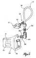
- figure 1 shows a perspective view of a hearing aid according to a form of embodiment of the present invention
- figure 2a , 2b and 2c show cross-section views of the hearing aids in figure 1 , along the cross-section plane II-II of figure 1 , according to different forms of embodiment of the present invention
- figure 3 shows a cross-section view of detail III of the hearing aid in figure 1 ;
- figure 4 shows a perspective view of a hearing aid according to a further form of embodiment of the present invention.
- figure 5 shows a perspective view in separate parts of a hearing aid according to a further form of embodiment of the present invention
- figure 6 shows a perspective view of a detail of a hearing aid according to a further form of embodiment of the present invention
- FIGS 7-9 show perspective views from different angles, of examples of insertion in the ear canal of the hearing aids according to present invention.
- reference numeral 4 is taken to globally denote a hearing aid suitable for inserting in an outer ear canal 8.
- the hearing aid 4 comprises a microphone 12 able to pick up sounds from the external environment; such microphone may be of the unidirectional or omnidirectional type.
- the hearing aid 4 comprises a circuit 16, electrically connected to the microphone 12, able to amplify the signals received from the microphone 12.
- the circuit 16 may, for example, be fitted with digital filters to cut out some frequencies or other devices able to process the sound signal.
- the hearing aid 4 also comprises a receiver 20 electrically connected to the circuit 16 and able to convey sounds into the ear canal 8, as well as a power supply 24 of the circuit 16, such as for example, a battery of a known type.
- the hearing aid 4 comprises a body of the hearing aid 28, suitable for insertion in the ear canal 8, which houses the circuit 16, the receiver 20 and the power supply 24 internally.
- the body of the hearing aid 28 is an ITE portion of the hearing aid according to the present invention, suitable for insertion in the external ear canal 8.
- the microphone 12 is situated outside the body of the hearing aid 28 and is connected to it by means of a connection and attachment tube 36 which creates an electrical connection between the circuit 16 and the microphone 12, as well as providing a secure and stable attachment of the microphone to the ear.
- the microphone is the BTE portion of the hearing aid of the present invention.
- connection and attachment tube 36 is configured so as to constitute a support element for the microphone 12 and an attachment element of the hearing aid 4 to the ear 40.
- connection and attachment tube goes from a first extremity 64, where it connects to the microphone 12, to a second extremity 68, where it connects to the body of the hearing aid 28.
- connection and attachment tube 36 comprises an external casing 44 which contains inside it an electric conductor wire 48 able to form an electrical connection between the microphone 12 and the circuit 16.
- the external casing 44 is made from non-allergenic, electrically insulated material.
- connection and attachment tube 36 comprises a core 37, preferably made using a cable, for example in metallic material.
- said core 37 is covered by a sheath 38, for example in polymer material, so as to electrically insulate the core 37.
- the electrical conductor wires 48 are situated in the space 39 between the core 37 and the tube.
- the core 37 makes the connection and attachment tube 36 flexible so that in the event of the tube 36 being bent it ensures a flexible effect of the curved tube.
- said space 39 has a circular crown cross-section ( figure 2a ).
- the internal cross-section of the tube 36 is divided into two parts by an inner septum 40.
- the septum 40 has an arched shape so as to define a ring-shaped seat 43 able to house said core 37 of the connection and attachment tube 36 ( figure 2b ).
- said inner septum,40 divides the tube into two practically symmetrical portions 54, with an essentially semi-circular cross-section, able to house the core 37 and the electrical conductor wires 48 ( figure 2c ).
- the septum 40 ensures that no contacts and/or friction between the electrical conductor wires 48 and the core 37 occur.
- the septum 40 makes the connection and attachment tube 36 more resistant and ensures that the tube 36 maintains its curved configuration.
- connection tube 36 is made in a rectilinear shape ( figure 1 ) so that subsequently it can be bent as required in the light of the morphology of the ear which it is to be applied to.
- connection and attachment tube 36 is bent so that , in a rest configuration in which it is not worn by the user, it comprises a hook portion 41 which closes into a ring shape, so as to form a sort of flexible hook able to fasten the hearing aid to the ear.
- the tube closes onto a hook portion 41 ( figures 4,5 ).
- the hook portion 41 is flexibly opened and hooked onto the ear. Thanks to the core 37, the hook portion 41 tends to pinch the ear, creating a firm and safe attachment which ensures the immobility of the microphone 12.
- the hook portion 41 is curved on the side opposite the body of the hearing aid 28 so as to position the microphone 12 in a close position to the ear 40.
- connection and attachment tube 36 has a curved section 52 able to adapt to the morphology of the portion of the ear connected to the head.
- the hearing aid 4 comprises a containment casing 60 of the microphone 12 which houses the microphone 12.
- connection and attachment tube 36 at its first extremity 64, is connected to the containment casing 60.
- the first extremity 64 has a connection portion 58 able to create an axial connection between the tube and the connectable containment casing 60.
- connection portion 58 permits relative rotation between the extremity 64 and the containment casing 60.
- connection portion 58 comprises at least one tab 59, for example ring-shaped, which by means of a snap coupling, preferably shaped, makes it possible to snap the extremity 64 of the tube 36 onto the casing 60.
- the extremity 64 can be snapped onto a collar 53 of the casing 60. This way, thanks to the relative rotation of the casing in relation to the first extremity 64,it is possible to adapt the hearing aid to the exact morphology of the wearer.
- connection and attachment tube 36 is made in one piece with the containment casing 60.
- the second extremity 68 of the connection and attachment tube 36 is connected mechanically to a closing cap 72 of the body of the hearing aid 28.
- the closing cap 72 can be removed from the body of the hearing aid 28 so as to enable access to the inside of the body of the hearing aid.
- the closing cap 72 comprises an access hatch 76 to the power supply 24, such as batteries.
- connection and attachment tube 36 at the second extremity 68, comprises a connection portion 58 able to create an axial connection between the tube and the associable body of the hearing aid 28.
- connection portion 58 permits relative rotation between the second extremity 68 of the tube 36 and the body of the hearing aid 28.
- the connection portion 58 comprises at least one tab 59, for example ring-shaped, which by means of a snap coupling, preferably shaped, makes it possible to snap the second extremity 68 of the tube 36 onto the body of the hearing aid 28.
- This way thanks to the relative rotation of the body 28 in relation to the second extremity 68,it is possible to adapt the hearing aid to the exact morphology of the ear of the wearer.
- a joint 89 which comprises a collar able to receive the connection portion 58 of the tube 36 and a further connection portion 58 suitable for attachment to the body of the hearing aid 28.
- connection and attachment tube 36 at the second extremity 68, comprises electric wires 48 at least partially sunk and fixed in the thickness of the wall of the tube 36; the second extremity 68 comprises a pair of slots 92, preferably positioned at 180 degrees from each other.
- the body of the hearing aid 28, preferably the joint 89, comprises an electric connection terminal board 90 which printed electric circuit boards 91 are sunk into, electrically connected to the electric components housed in the body of the hearing aid 28.
- the electric connection terminal board 590 comprises two series of printed electric circuit boards 91, positioned symmetrically to each other at 180 degrees, so that by turning the second extremity 68 by 180 degrees in relation to the printed electric circuit boards 91, to change from the right configuration to the left configuration and/or vice versa, the electrical connection between the body of the hearing aid 28 and the tube 36 is always ensured.
- the electric wires 48 of the second extremity 68 overlap the printed electric circuit boards 91 after connecting the second extremity 68 of the tube 36 to the body, creating an electrical connection between the tube and the body of the hearing aid 28.
- the electric connection terminal board 90 comprises at least one raised part 93 able to form a shaped coupling with said slots 92.
- the slots 92 of the second extremity 68 positioned at 180 degrees to each other, couple with the raised part 93 situated on the joint 89 and ensure the correct angular position and relative electrical connection between the second extremity 68 of the tube 36 and the body of the hearing aid 8.
- the second extremity 68 of the tube 36 fits into the closing cap 72 of the body, by means of interposed bushing 94, for example in polymeric material, to prevent friction and excessive curvature of the tube 36 at the second extremity 68.
- connection and attachment tube 36, at the second extremity 68, is made in one piece with the closing cap 72 of the body of the hearing aid 28.
- the containment casing 60 of the microphone 12 comprises at least one aperture 80 for the connection of the microphone 12 with the outside of the casing 60.
- said aperture 80 faces the opposite way to the body of the hearing aid 28 as well as to a support surface of the relative ear.
- the containment casing 60 of the microphone comprises blocking devices 84 of the microphone inside it.
- the blocking devices 84 comprise at least one strip 88 able to flexibly direct the microphone 12 against an inner wall of said casing, opposite the said strip.
- the blocking devices once removed, enable extraction of the microphone 12 from its casing 60.
- the body of the hearing aid 28 may comprise at least one ventilation channel (not shown) able to allow the passage of air through the body of the hearing aid 28, so as to allow the ear canal 8, which receives the body of the hearing aid 28, to communicate with the external environment.
- the phenomenon of autophony can also be reduced by using a casing or body of the hearing aid 28 which is smaller than the ear canal, avoiding the 'Larsen' phenomenon in any case thanks to the specific distance and position of the microphone, behind the ear which thus constitutes a further obstacle to the onset of the 'Larsen' effect.
- the body of the hearing aid 28 may be a truncated cone shape with a slot, suitable for application in very small ear canals ( figure 1 ).
- the hearing aid according to the invention makes it possible to overcome the drawbacks referred to in the technical note.
- the hearing aid according to the present invention makes it possible to distance the microphone from the receiver eliminating the phenomenon of acoustic feedback, at the same time permitting a variety of applications ranging from medium hearing loss to severe deafness, impossible to achieve with known, state-of- the-hearing aids.
- the hearing aid according to the present invention is extremely advantageous given that it makes for particularly limited dimensions of the external portion, making it comparable to a hearing aid of the ITE type.
- the dimensions and conformation of the hearing aid of the present invention also permit greater comfort and convenience.
- connection and attachment tube has such flexible properties as to make it suitable for any anatomical conformation of the wearer. Thanks to the elasticity of the tube, given by the core of the tube, the tube acts as a hook on the ear and ensures secure attachment over time, preventing shifting during normal use.
- the tube has such characteristics of dimension and weight as to make it practically invisible from outside and is not perceived by the wearer.
- connection and attachment tube can be adapted to any morphology of the wearer.
- the hearing aid can be converted from right to left and vice versa by exploiting the bendiness of the tube.
- the core means that following a rotation of 180 degrees of the tube, the said tube maintains the new curvature assumed.
- connection portions at the extremities of the tube may be facilitated by the use of connection portions at the extremities of the tube.
- connection and attachment tube has a double shaping or curvature, given by the hook portion and by the curved section, making perfect adherence possible both on the outside part of the ear and in the part positioned behind the ear.
- connection tube has an anatomical form which ensures comfort and convenience and which at the same time improves the acoustic features of the hearing aid.
- the hearing aid of the present invention is free from feedback phenomena, given that the microphone is situated at a considerable distance from the receiver.
- the hearing aid therefore offers a practically unlimited range of applications in cases of over 80 dB of hearing loss.
- the BTE portion of the present hearing aid is particularly small and light in that it comprises solely the microphone.
- the relatively large and heavy components of the hearing aid such as the battery and the electronic components are in fact all contained in the body of the hearing aid lodged in the ear canal.
Landscapes
- Health & Medical Sciences (AREA)
- General Health & Medical Sciences (AREA)
- Neurosurgery (AREA)
- Otolaryngology (AREA)
- Physics & Mathematics (AREA)
- Engineering & Computer Science (AREA)
- Acoustics & Sound (AREA)
- Signal Processing (AREA)
- Headphones And Earphones (AREA)
- Finger-Pressure Massage (AREA)
- Adornments (AREA)
- Prostheses (AREA)
Claims (15)
- Hörgerät (4) umfassend- ein Mikrophon (12), einen Schaltkreis (16), der mit dem Mikrophon (12) elektrisch leitend verbunden ist und im Stande ist, die Signale, die vom Mikrophon (12) empfangen werden, zu verstärken, einen Empfänger (20), der mit dem Schaltkreis (16) elektrisch leitend verbunden ist und im Stande ist, Töne an den Gehörgang (8) zu übermitteln, eine Stromversorgung (24) des Schaltkreises (16),- wobei das Hörgerät (4) einen Hörgerätekörper (28) umfasst, in dem der Schaltkreis (16), der Empfänger (20) und die Stromversorgung (24) aufgenommen sind, wobei der Hörgerätekörper (28) geeignet ist, in den Gehörgang (8) eingeführt zu werden,
wobei- das Mikrophon (12) außerhalb des Hörgerätekörpers (28) angeordnet ist und mittels eines Verbindungs- und Befestigungsrohres (36), das eine elektrisch leitende Verbindung zwischen dem Schaltkreis (16) und dem Mikrophon (12) erzeugt und das Hörgerät an dem Ohr festlegt, mit diesem verbunden ist,- das Verbindungs- und Befestigungsrohr (36) sich von einem ersten Ende (64), an dem es mit dem Mikrophon (12) verbunden ist, zu einem zweiten Ende (68), an dem es mit Hörgerätekörper (28) verbunden ist, erstreckt,
dadurch gekennzeichnet,
dass das Verbindungs- und Befestigungsrohr (36) einen Hakenabschnitt (41) umfasst, der derart aufgebaut ist, dass er ein Stützelement des Mikrophons (12) und ein elastisches Element zum Festhaken des Mikrophons (12) an dem Ohr (40) bildet, wobei das Verbindungs- und Befestigungsrohr (36) derart gebogen ist, dass es in einer Ruhekonfiguration, in der es nicht von dem Benutzer getragen wird, einen Hakenabschnitt (41) umfasst, der derart mit einer Ringform schließt, dass eine Art flexibler Haken gebildet wird, der im Stande ist, das Hörgerät an dem Ohr festzulegen. - Hörgerät (4) gemäß Anspruch 1, wobei das Verbindungs- und Befestigungsrohr (36) ein Außengehäuse (44) umfasst, das im Inneren wenigstens einen elektrisch leitenden Leiterdraht (48) enthält, der im Stande ist, eine elektrisch leitende Verbindung zwischen dem Mikrophon (12) und dem Schaltkreis (16) zu bilden.
- Hörgerät (4) gemäß irgend einem der vorangehenden Ansprüche, wobei das Verbindungsrohr (36) in einer geradlinigen Form ausgebildet und danach gebogen wird, um den Hakenabschnitt (41) unter Berücksichtigung der Morphologie des Ohres zu bilden, wobei der Kern (37) sicherstellt, dass er seinen gebogenen Aufbau und die flexible Wirkung des Hakenabschnitts (41) aufrechterhält.
- Hörgerät (4) gemäß irgend einem der vorangehenden Ansprüche, wobei der Hakenabschnitt (41) an der dem Hörgerätekörper (28) entgegengesetzten Sei-te derart gebogen ist, dass das Mikrophon (12) in einer engen Position zu dem Ohr (40) angeordnet ist.
- Hörgerät (4) gemäß irgend einem der vorangehenden Ansprüche, wobei das Verbindungs- und Befestigungsrohr (36) einen gebogenen Abschnitt (52) aufweist, der an die Morphologie des Abschnitts des Ohres (40), der mit dem Kopf verbunden ist, anpassbar ist.
- Hörgerät (4) gemäß irgend einem der vorangehenden Ansprüche, wobei das Verbindungs- und Befestigungsrohr (36) an dem zweiten Ende (68) elektrisch leitende Drähte (48) umfasst, die wenigstens teilweise in der Dicke der Wand des Rohres (36) eingelassen und befestigt sind, und wobei der Hörgerätekör-per (28) eine elektrische Anschlussplatte (90) umfasst, deren gedruckte elektrische Schaltkreisplatten (91) in den elektrischen Bauteilen eingelassen und mit diesen elektrisch leitend verbunden sind, die in dem Hörgerätekörper (28) aufgenommen sind.
- Hörgerät (4) gemäß Anspruch 6, wobei die elektrische Anschlussplatte (90) zwei Reihen von gedruckten elektrischen Schaltkreisplatten (91) umfasst, die um 180° zueinander symmetrisch angeordnet sind, so dass durch Drehen des zweiten Endes (68) um 180° in Beziehung zu der gedruckten elektrischen Schaltkreisplatte (91), zur Veränderung von dem rechten Aufbau zu dem linken Aufbau und/oder umgekehrt, die elektrisch leitende Verbindung zwischen dem Hörgerätekörper (28) und dem Verbindungs- und Befesti-gungsrohr (36) stets sichergestellt ist.
- Hörgerät (4) gemäß Anspruch 6 oder 7, wobei das zweite Ende (68) zwei ein Paar bildende Schlitze (92) umfasst und der Hörgerätekörper (28) einen erhöhten Abschnitt (93) umfasst, der eine Formschlussverbindung mit den Schlitzen (92) bilden kann, um die Ausrichtung und die elektrisch leitende Verbindung zwischen der gedruckten elektrischen Anschlussplatte (91) und den elektrischen Drähten (48) des Rohres (36) sicherzustellen.
- Hörgerät (4) gemäß Anspruch 8, wobei die Schlitze (92) des zweiten Endes (68) um 180 ° zueinander angeordnet sind, um die korrekte Winkelposition und die entsprechende elektrisch leitende Verbindung zwischen dem zweiten Ende (68) des Rohres (36) und dem Hörgerätkörper (8) beim Ändern von einem rechten auf einen linken Aufbau des Hörgeräts sicherzustellen.
- Hörgerät (4) gemäß irgend einem der vorangehenden Ansprüche, wobei das zweite Ende (68) des Rohres (36) in eine Verschlusskappe (72) des Hörgerä-tekörpers (28) mittels einer zwischengeschalteten Hülse (94) passt.
- Hörgerät (4) gemäß irgend einem der vorangehenden Ansprüche, wobei das Verbindungs- und Befestigungsrohr (36) mit einem Aufnahmegehäuse (60) des Mikrophons (12) und/oder mit einer Verschlusskappe (72) des Hörgerätekörpers (28) einstückig ausgebildet ist.
- Hörgerät (4) gemäß irgend einem der vorangehenden Ansprüche, wobei das Aufnahmegehäuse (60) des Mikrophons (12) wenigstens eine Öffnung (80) für die Verbindung des Mikrophons (12) mit der Außenseite des Gehäuses (60) umfasst.
- Hörgerät (4) gemäß Anspruch 12, wobei die Öffnung (80) in entgegen-gesetzter Richtung zu dem Hörgerätekörper (28) als auch zu einer Stützfläche des jeweiligen Ohres weist.
- Hörgerät (4) gemäß irgend einem der vorangehenden Ansprüche, wobei ein Aufnahmegehäuse (60) des Mikrophons (12) Sperrvorrichtungen (84) für das Mikrophon im Inneren umfasst.
- Hörgerät (4) gemäß irgend einem der vorangehenden Ansprüche, wobei der Hörgerätekörper (28) wenigstens einen Belüftungskanal umfasst, der im Stan-de ist, das Passieren eines Luftstroms durch den Hörgerätekörper (28) zu er-möglichen, um zu erlauben, dass der Gehörgang (8), der den Hörgerätekörper (28) aufnimmt, mit der Außenumgebung kommuniziert.
Applications Claiming Priority (2)
| Application Number | Priority Date | Filing Date | Title |
|---|---|---|---|
| IT000113A ITBS20070113A1 (it) | 2007-07-30 | 2007-07-30 | Protesi acustica |
| PCT/IT2007/000916 WO2009016671A1 (en) | 2007-07-30 | 2007-12-27 | Hearing aid |
Publications (2)
| Publication Number | Publication Date |
|---|---|
| EP2060150A1 EP2060150A1 (de) | 2009-05-20 |
| EP2060150B1 true EP2060150B1 (de) | 2010-04-28 |
Family
ID=38441607
Family Applications (1)
| Application Number | Title | Priority Date | Filing Date |
|---|---|---|---|
| EP07866847A Not-in-force EP2060150B1 (de) | 2007-07-30 | 2007-12-27 | Hörgerät |
Country Status (8)
| Country | Link |
|---|---|
| US (1) | US20100195859A1 (de) |
| EP (1) | EP2060150B1 (de) |
| AT (1) | ATE466458T1 (de) |
| DE (1) | DE602007006210D1 (de) |
| DK (1) | DK2060150T3 (de) |
| ES (1) | ES2345224T3 (de) |
| IT (1) | ITBS20070113A1 (de) |
| WO (1) | WO2009016671A1 (de) |
Families Citing this family (7)
| Publication number | Priority date | Publication date | Assignee | Title |
|---|---|---|---|---|
| DE102009032981B4 (de) | 2009-07-14 | 2013-11-28 | Siemens Medical Instruments Pte. Ltd. | Hörerschlauch |
| WO2010089422A2 (en) * | 2010-05-25 | 2010-08-12 | Phonak Ag | Hearing device |
| DE102010041524A1 (de) | 2010-09-28 | 2012-02-02 | Siemens Medical Instruments Pte. Ltd. | Hörhilfeapparat mit elastischem Hörerschlauch |
| US20150043766A1 (en) * | 2013-08-09 | 2015-02-12 | Otorix AB | Hearing device system |
| ES2647672B1 (es) * | 2016-06-24 | 2018-10-10 | Victor Gustavo SLAVUTSKY JOISON | Dispositivo de estimulación auditiva |
| WO2018117997A1 (en) * | 2016-12-20 | 2018-06-28 | Williams Todd Edward | Active earmolds |
| JP7614907B2 (ja) | 2021-03-30 | 2025-01-16 | リオン株式会社 | 補聴器、線状部材ユニット、及び、治工具 |
Family Cites Families (13)
| Publication number | Priority date | Publication date | Assignee | Title |
|---|---|---|---|---|
| US3783201A (en) * | 1970-12-02 | 1974-01-01 | Beltone Electronics Corp | Miniature hearing aid structure |
| DE8814162U1 (de) * | 1988-11-11 | 1988-12-29 | Hörgeräte Geers GmbH & Co. KG, 4600 Dortmund | Hörgerät |
| GB2239162B (en) | 1989-10-14 | 1993-08-04 | David Anthony Batten | Flexible earphone bands |
| US6275596B1 (en) * | 1997-01-10 | 2001-08-14 | Gn Resound Corporation | Open ear canal hearing aid system |
| US5987146A (en) * | 1997-04-03 | 1999-11-16 | Resound Corporation | Ear canal microphone |
| US6181801B1 (en) * | 1997-04-03 | 2001-01-30 | Resound Corporation | Wired open ear canal earpiece |
| US5875254A (en) * | 1997-12-18 | 1999-02-23 | Siemens Hearing Instruments, Inc. | Binaural hearing aid with integrated retrieval line and microphone |
| DE29801567U1 (de) * | 1998-01-30 | 1998-04-16 | Siemens Audiologische Technik | Hinter dem Ohr tragbares Hörhilfegerät |
| DE19858399C2 (de) * | 1998-12-17 | 2003-02-20 | Phonak Ag Staefa | Elektroakustischer Wandler für Hörgeräte zur Luftschallabstrahlung in den äußeren Gehörgang |
| WO2002052890A1 (en) * | 2000-12-22 | 2002-07-04 | Nextlink.To A/S | An acoustic device with means for being secured in a human ear |
| US7421086B2 (en) * | 2002-09-10 | 2008-09-02 | Vivatone Hearing Systems, Llc | Hearing aid system |
| DE102004036860B3 (de) * | 2004-07-29 | 2006-01-19 | Bruckhoff Apparatebau Gmbh | Hörgerät und Verfahren zu dessen Herstellung |
| DE102004044318B3 (de) * | 2004-09-10 | 2005-11-24 | Hansaton Akustik Gmbh | Schlauchförmige Verbindungsleitung für ein Hörgerät und Hörgerät |
-
2007
- 2007-07-30 IT IT000113A patent/ITBS20070113A1/it unknown
- 2007-12-27 EP EP07866847A patent/EP2060150B1/de not_active Not-in-force
- 2007-12-27 WO PCT/IT2007/000916 patent/WO2009016671A1/en not_active Ceased
- 2007-12-27 AT AT07866847T patent/ATE466458T1/de not_active IP Right Cessation
- 2007-12-27 DK DK07866847.2T patent/DK2060150T3/da active
- 2007-12-27 ES ES07866847T patent/ES2345224T3/es active Active
- 2007-12-27 US US12/671,353 patent/US20100195859A1/en not_active Abandoned
- 2007-12-27 DE DE602007006210T patent/DE602007006210D1/de active Active
Also Published As
| Publication number | Publication date |
|---|---|
| DE602007006210D1 (de) | 2010-06-10 |
| US20100195859A1 (en) | 2010-08-05 |
| ATE466458T1 (de) | 2010-05-15 |
| ITBS20070113A1 (it) | 2009-01-31 |
| ES2345224T3 (es) | 2010-09-17 |
| EP2060150A1 (de) | 2009-05-20 |
| DK2060150T3 (da) | 2010-08-09 |
| WO2009016671A1 (en) | 2009-02-05 |
Similar Documents
| Publication | Publication Date | Title |
|---|---|---|
| EP2449797B1 (de) | Hörgerät mit lüftungserweiterung | |
| EP2060150B1 (de) | Hörgerät | |
| EP3748992B1 (de) | Hörgeräteeinheit entlang einer einzelnen gekrümmten achse | |
| EP1510104B1 (de) | Äusserer ohreinsatz zum verbessern der hörverständlichkeit | |
| EP2033487B1 (de) | Hörgerät mit einem länglichen glied | |
| US7899200B2 (en) | Universal-fit hearing device | |
| US8755549B2 (en) | Universal flexible in-the-ear hearing aid | |
| US6094493A (en) | Hearing aid | |
| CN102006543B (zh) | 一种新型耳内助听器 | |
| US20040165742A1 (en) | Canal hearing device with tubular insert | |
| US20100166241A1 (en) | Hearing aid ear dome | |
| US20120237068A1 (en) | Soft Concha Ring Behind-The-Ear Hearing Aid | |
| EP3334179B1 (de) | Hörgerät mit einer erweiterten kuppel | |
| EP4007302A1 (de) | Ohrstück einer hörvorrichtung mit geneigtem mikrofon/empfänger | |
| EP2025202B1 (de) | Universell passendes hörgerät | |
| CN202077178U (zh) | 一种新型耳内助听器 | |
| CN215581652U (zh) | 一种新型耳机及助听器 | |
| CN207995394U (zh) | 一种耳腔式助听器 | |
| Natalizia et al. | Hearing loss in older adults: perspectives for rehabilitation with customised hearing aids and a follow-up fitting procedure |
Legal Events
| Date | Code | Title | Description |
|---|---|---|---|
| PUAI | Public reference made under article 153(3) epc to a published international application that has entered the european phase |
Free format text: ORIGINAL CODE: 0009012 |
|
| 17P | Request for examination filed |
Effective date: 20090226 |
|
| AK | Designated contracting states |
Kind code of ref document: A1 Designated state(s): AT BE BG CH CY CZ DE DK EE ES FI FR GB GR HU IE IS IT LI LT LU LV MC MT NL PL PT RO SE SI SK TR |
|
| AX | Request for extension of the european patent |
Extension state: AL BA HR MK RS |
|
| 17Q | First examination report despatched |
Effective date: 20090810 |
|
| GRAP | Despatch of communication of intention to grant a patent |
Free format text: ORIGINAL CODE: EPIDOSNIGR1 |
|
| RTI1 | Title (correction) |
Free format text: HEARING AID |
|
| DAX | Request for extension of the european patent (deleted) | ||
| GRAS | Grant fee paid |
Free format text: ORIGINAL CODE: EPIDOSNIGR3 |
|
| GRAA | (expected) grant |
Free format text: ORIGINAL CODE: 0009210 |
|
| AK | Designated contracting states |
Kind code of ref document: B1 Designated state(s): AT BE BG CH CY CZ DE DK EE ES FI FR GB GR HU IE IS IT LI LT LU LV MC MT NL PL PT RO SE SI SK TR |
|
| REG | Reference to a national code |
Ref country code: GB Ref legal event code: FG4D |
|
| REG | Reference to a national code |
Ref country code: CH Ref legal event code: EP |
|
| REG | Reference to a national code |
Ref country code: IE Ref legal event code: FG4D |
|
| REF | Corresponds to: |
Ref document number: 602007006210 Country of ref document: DE Date of ref document: 20100610 Kind code of ref document: P |
|
| REG | Reference to a national code |
Ref country code: CH Ref legal event code: NV Representative=s name: JACOBACCI & PARTNERS S.P.A. |
|
| REG | Reference to a national code |
Ref country code: NL Ref legal event code: T3 |
|
| REG | Reference to a national code |
Ref country code: DK Ref legal event code: T3 |
|
| REG | Reference to a national code |
Ref country code: ES Ref legal event code: FG2A Ref document number: 2345224 Country of ref document: ES Kind code of ref document: T3 |
|
| LTIE | Lt: invalidation of european patent or patent extension |
Effective date: 20100428 |
|
| PG25 | Lapsed in a contracting state [announced via postgrant information from national office to epo] |
Ref country code: SE Free format text: LAPSE BECAUSE OF FAILURE TO SUBMIT A TRANSLATION OF THE DESCRIPTION OR TO PAY THE FEE WITHIN THE PRESCRIBED TIME-LIMIT Effective date: 20100428 Ref country code: LT Free format text: LAPSE BECAUSE OF FAILURE TO SUBMIT A TRANSLATION OF THE DESCRIPTION OR TO PAY THE FEE WITHIN THE PRESCRIBED TIME-LIMIT Effective date: 20100428 |
|
| PG25 | Lapsed in a contracting state [announced via postgrant information from national office to epo] |
Ref country code: SI Free format text: LAPSE BECAUSE OF FAILURE TO SUBMIT A TRANSLATION OF THE DESCRIPTION OR TO PAY THE FEE WITHIN THE PRESCRIBED TIME-LIMIT Effective date: 20100428 Ref country code: IS Free format text: LAPSE BECAUSE OF FAILURE TO SUBMIT A TRANSLATION OF THE DESCRIPTION OR TO PAY THE FEE WITHIN THE PRESCRIBED TIME-LIMIT Effective date: 20100828 Ref country code: FI Free format text: LAPSE BECAUSE OF FAILURE TO SUBMIT A TRANSLATION OF THE DESCRIPTION OR TO PAY THE FEE WITHIN THE PRESCRIBED TIME-LIMIT Effective date: 20100428 Ref country code: AT Free format text: LAPSE BECAUSE OF FAILURE TO SUBMIT A TRANSLATION OF THE DESCRIPTION OR TO PAY THE FEE WITHIN THE PRESCRIBED TIME-LIMIT Effective date: 20100428 Ref country code: LV Free format text: LAPSE BECAUSE OF FAILURE TO SUBMIT A TRANSLATION OF THE DESCRIPTION OR TO PAY THE FEE WITHIN THE PRESCRIBED TIME-LIMIT Effective date: 20100428 |
|
| PG25 | Lapsed in a contracting state [announced via postgrant information from national office to epo] |
Ref country code: PL Free format text: LAPSE BECAUSE OF FAILURE TO SUBMIT A TRANSLATION OF THE DESCRIPTION OR TO PAY THE FEE WITHIN THE PRESCRIBED TIME-LIMIT Effective date: 20100428 Ref country code: CY Free format text: LAPSE BECAUSE OF FAILURE TO SUBMIT A TRANSLATION OF THE DESCRIPTION OR TO PAY THE FEE WITHIN THE PRESCRIBED TIME-LIMIT Effective date: 20100609 |
|
| PG25 | Lapsed in a contracting state [announced via postgrant information from national office to epo] |
Ref country code: EE Free format text: LAPSE BECAUSE OF FAILURE TO SUBMIT A TRANSLATION OF THE DESCRIPTION OR TO PAY THE FEE WITHIN THE PRESCRIBED TIME-LIMIT Effective date: 20100428 Ref country code: PT Free format text: LAPSE BECAUSE OF FAILURE TO SUBMIT A TRANSLATION OF THE DESCRIPTION OR TO PAY THE FEE WITHIN THE PRESCRIBED TIME-LIMIT Effective date: 20100830 |
|
| PG25 | Lapsed in a contracting state [announced via postgrant information from national office to epo] |
Ref country code: SK Free format text: LAPSE BECAUSE OF FAILURE TO SUBMIT A TRANSLATION OF THE DESCRIPTION OR TO PAY THE FEE WITHIN THE PRESCRIBED TIME-LIMIT Effective date: 20100428 Ref country code: RO Free format text: LAPSE BECAUSE OF FAILURE TO SUBMIT A TRANSLATION OF THE DESCRIPTION OR TO PAY THE FEE WITHIN THE PRESCRIBED TIME-LIMIT Effective date: 20100428 Ref country code: CZ Free format text: LAPSE BECAUSE OF FAILURE TO SUBMIT A TRANSLATION OF THE DESCRIPTION OR TO PAY THE FEE WITHIN THE PRESCRIBED TIME-LIMIT Effective date: 20100428 Ref country code: BE Free format text: LAPSE BECAUSE OF FAILURE TO SUBMIT A TRANSLATION OF THE DESCRIPTION OR TO PAY THE FEE WITHIN THE PRESCRIBED TIME-LIMIT Effective date: 20100428 |
|
| PLBE | No opposition filed within time limit |
Free format text: ORIGINAL CODE: 0009261 |
|
| STAA | Information on the status of an ep patent application or granted ep patent |
Free format text: STATUS: NO OPPOSITION FILED WITHIN TIME LIMIT |
|
| 26N | No opposition filed |
Effective date: 20110131 |
|
| PG25 | Lapsed in a contracting state [announced via postgrant information from national office to epo] |
Ref country code: GR Free format text: LAPSE BECAUSE OF FAILURE TO SUBMIT A TRANSLATION OF THE DESCRIPTION OR TO PAY THE FEE WITHIN THE PRESCRIBED TIME-LIMIT Effective date: 20100729 |
|
| PG25 | Lapsed in a contracting state [announced via postgrant information from national office to epo] |
Ref country code: MC Free format text: LAPSE BECAUSE OF NON-PAYMENT OF DUE FEES Effective date: 20101231 |
|
| PG25 | Lapsed in a contracting state [announced via postgrant information from national office to epo] |
Ref country code: IE Free format text: LAPSE BECAUSE OF NON-PAYMENT OF DUE FEES Effective date: 20101227 |
|
| PG25 | Lapsed in a contracting state [announced via postgrant information from national office to epo] |
Ref country code: MT Free format text: LAPSE BECAUSE OF FAILURE TO SUBMIT A TRANSLATION OF THE DESCRIPTION OR TO PAY THE FEE WITHIN THE PRESCRIBED TIME-LIMIT Effective date: 20100428 Ref country code: IT Free format text: LAPSE BECAUSE OF NON-PAYMENT OF DUE FEES Effective date: 20101227 |
|
| PG25 | Lapsed in a contracting state [announced via postgrant information from national office to epo] |
Ref country code: BG Free format text: LAPSE BECAUSE OF FAILURE TO SUBMIT A TRANSLATION OF THE DESCRIPTION OR TO PAY THE FEE WITHIN THE PRESCRIBED TIME-LIMIT Effective date: 20100428 Ref country code: LU Free format text: LAPSE BECAUSE OF NON-PAYMENT OF DUE FEES Effective date: 20101227 Ref country code: HU Free format text: LAPSE BECAUSE OF FAILURE TO SUBMIT A TRANSLATION OF THE DESCRIPTION OR TO PAY THE FEE WITHIN THE PRESCRIBED TIME-LIMIT Effective date: 20101029 |
|
| PG25 | Lapsed in a contracting state [announced via postgrant information from national office to epo] |
Ref country code: TR Free format text: LAPSE BECAUSE OF FAILURE TO SUBMIT A TRANSLATION OF THE DESCRIPTION OR TO PAY THE FEE WITHIN THE PRESCRIBED TIME-LIMIT Effective date: 20100428 |
|
| PG25 | Lapsed in a contracting state [announced via postgrant information from national office to epo] |
Ref country code: BG Free format text: LAPSE BECAUSE OF FAILURE TO SUBMIT A TRANSLATION OF THE DESCRIPTION OR TO PAY THE FEE WITHIN THE PRESCRIBED TIME-LIMIT Effective date: 20100728 |
|
| PGFP | Annual fee paid to national office [announced via postgrant information from national office to epo] |
Ref country code: GB Payment date: 20141219 Year of fee payment: 8 Ref country code: CH Payment date: 20141219 Year of fee payment: 8 Ref country code: ES Payment date: 20141222 Year of fee payment: 8 |
|
| PGFP | Annual fee paid to national office [announced via postgrant information from national office to epo] |
Ref country code: NL Payment date: 20141219 Year of fee payment: 8 |
|
| REG | Reference to a national code |
Ref country code: CH Ref legal event code: PCAR Free format text: NEW ADDRESS: VIA LUGANETTO 3, 6962 LUGANO (CH) |
|
| PGFP | Annual fee paid to national office [announced via postgrant information from national office to epo] |
Ref country code: FR Payment date: 20141231 Year of fee payment: 8 |
|
| PGFP | Annual fee paid to national office [announced via postgrant information from national office to epo] |
Ref country code: DK Payment date: 20151230 Year of fee payment: 9 |
|
| PGFP | Annual fee paid to national office [announced via postgrant information from national office to epo] |
Ref country code: DE Payment date: 20160302 Year of fee payment: 9 |
|
| REG | Reference to a national code |
Ref country code: CH Ref legal event code: PL |
|
| GBPC | Gb: european patent ceased through non-payment of renewal fee |
Effective date: 20151227 |
|
| REG | Reference to a national code |
Ref country code: NL Ref legal event code: MM Effective date: 20160101 |
|
| REG | Reference to a national code |
Ref country code: FR Ref legal event code: ST Effective date: 20160831 |
|
| PG25 | Lapsed in a contracting state [announced via postgrant information from national office to epo] |
Ref country code: GB Free format text: LAPSE BECAUSE OF NON-PAYMENT OF DUE FEES Effective date: 20151227 Ref country code: LI Free format text: LAPSE BECAUSE OF NON-PAYMENT OF DUE FEES Effective date: 20151231 Ref country code: CH Free format text: LAPSE BECAUSE OF NON-PAYMENT OF DUE FEES Effective date: 20151231 Ref country code: NL Free format text: LAPSE BECAUSE OF NON-PAYMENT OF DUE FEES Effective date: 20160101 |
|
| PG25 | Lapsed in a contracting state [announced via postgrant information from national office to epo] |
Ref country code: FR Free format text: LAPSE BECAUSE OF NON-PAYMENT OF DUE FEES Effective date: 20151231 |
|
| PG25 | Lapsed in a contracting state [announced via postgrant information from national office to epo] |
Ref country code: ES Free format text: LAPSE BECAUSE OF NON-PAYMENT OF DUE FEES Effective date: 20151228 |
|
| REG | Reference to a national code |
Ref country code: DE Ref legal event code: R119 Ref document number: 602007006210 Country of ref document: DE |
|
| REG | Reference to a national code |
Ref country code: DK Ref legal event code: EBP Effective date: 20161231 |
|
| PG25 | Lapsed in a contracting state [announced via postgrant information from national office to epo] |
Ref country code: DE Free format text: LAPSE BECAUSE OF NON-PAYMENT OF DUE FEES Effective date: 20170701 |
|
| PG25 | Lapsed in a contracting state [announced via postgrant information from national office to epo] |
Ref country code: DK Free format text: LAPSE BECAUSE OF NON-PAYMENT OF DUE FEES Effective date: 20161231 |
|
| REG | Reference to a national code |
Ref country code: ES Ref legal event code: FD2A Effective date: 20180703 |
|
| PGFP | Annual fee paid to national office [announced via postgrant information from national office to epo] |
Ref country code: IT Payment date: 20201207 Year of fee payment: 14 |
|
| PG25 | Lapsed in a contracting state [announced via postgrant information from national office to epo] |
Ref country code: IT Free format text: LAPSE BECAUSE OF NON-PAYMENT OF DUE FEES Effective date: 20211227 |