EP2059832B1 - Sonar mit verformbarer antenne und entsprechendes signalverarbeitungsverfahren zur herstellung einer synthetischen antenne - Google Patents
Sonar mit verformbarer antenne und entsprechendes signalverarbeitungsverfahren zur herstellung einer synthetischen antenne Download PDFInfo
- Publication number
- EP2059832B1 EP2059832B1 EP07823787.2A EP07823787A EP2059832B1 EP 2059832 B1 EP2059832 B1 EP 2059832B1 EP 07823787 A EP07823787 A EP 07823787A EP 2059832 B1 EP2059832 B1 EP 2059832B1
- Authority
- EP
- European Patent Office
- Prior art keywords
- antenna
- acoustic
- head
- physical antenna
- sonar
- Prior art date
- Legal status (The legal status is an assumption and is not a legal conclusion. Google has not performed a legal analysis and makes no representation as to the accuracy of the status listed.)
- Active
Links
- 238000000034 method Methods 0.000 title claims description 10
- 238000012545 processing Methods 0.000 title claims description 6
- 238000003384 imaging method Methods 0.000 claims description 3
- 230000001066 destructive effect Effects 0.000 claims description 2
- 238000001514 detection method Methods 0.000 claims description 2
- 241000251468 Actinopterygii Species 0.000 description 10
- 238000004891 communication Methods 0.000 description 7
- 230000005540 biological transmission Effects 0.000 description 5
- 230000015572 biosynthetic process Effects 0.000 description 4
- 230000010363 phase shift Effects 0.000 description 4
- 230000005484 gravity Effects 0.000 description 3
- 238000006073 displacement reaction Methods 0.000 description 2
- 238000003672 processing method Methods 0.000 description 2
- 238000003786 synthesis reaction Methods 0.000 description 2
- 230000001133 acceleration Effects 0.000 description 1
- 230000015556 catabolic process Effects 0.000 description 1
- 238000006731 degradation reaction Methods 0.000 description 1
- 230000010365 information processing Effects 0.000 description 1
- 230000003287 optical effect Effects 0.000 description 1
- 239000013307 optical fiber Substances 0.000 description 1
- 238000011160 research Methods 0.000 description 1
- 230000000630 rising effect Effects 0.000 description 1
- 239000013535 sea water Substances 0.000 description 1
- 239000002689 soil Substances 0.000 description 1
- 239000007787 solid Substances 0.000 description 1
- 230000002123 temporal effect Effects 0.000 description 1
- 238000012546 transfer Methods 0.000 description 1
- 238000013519 translation Methods 0.000 description 1
Images
Classifications
-
- G—PHYSICS
- G01—MEASURING; TESTING
- G01S—RADIO DIRECTION-FINDING; RADIO NAVIGATION; DETERMINING DISTANCE OR VELOCITY BY USE OF RADIO WAVES; LOCATING OR PRESENCE-DETECTING BY USE OF THE REFLECTION OR RERADIATION OF RADIO WAVES; ANALOGOUS ARRANGEMENTS USING OTHER WAVES
- G01S15/00—Systems using the reflection or reradiation of acoustic waves, e.g. sonar systems
- G01S15/88—Sonar systems specially adapted for specific applications
- G01S15/89—Sonar systems specially adapted for specific applications for mapping or imaging
- G01S15/8902—Side-looking sonar
- G01S15/8904—Side-looking sonar using synthetic aperture techniques
-
- G—PHYSICS
- G01—MEASURING; TESTING
- G01S—RADIO DIRECTION-FINDING; RADIO NAVIGATION; DETERMINING DISTANCE OR VELOCITY BY USE OF RADIO WAVES; LOCATING OR PRESENCE-DETECTING BY USE OF THE REFLECTION OR RERADIATION OF RADIO WAVES; ANALOGOUS ARRANGEMENTS USING OTHER WAVES
- G01S7/00—Details of systems according to groups G01S13/00, G01S15/00, G01S17/00
- G01S7/52—Details of systems according to groups G01S13/00, G01S15/00, G01S17/00 of systems according to group G01S15/00
- G01S7/521—Constructional features
-
- G—PHYSICS
- G01—MEASURING; TESTING
- G01V—GEOPHYSICS; GRAVITATIONAL MEASUREMENTS; DETECTING MASSES OR OBJECTS; TAGS
- G01V1/00—Seismology; Seismic or acoustic prospecting or detecting
- G01V1/38—Seismology; Seismic or acoustic prospecting or detecting specially adapted for water-covered areas
- G01V1/3817—Positioning of seismic devices
- G01V1/3835—Positioning of seismic devices measuring position, e.g. by GPS or acoustically
Definitions
- the subject of the present invention is that of sonar imaging in a marine environment. More particularly, the invention relates to an improved sonar and an associated method of signal processing.
- an underwater device or fish
- the flanks of the fish carry respectively sonar, said side.
- the acoustic antenna of each of these lateral sonars is formed by a row of a plurality of transducers operating in reception, associated with at least one transducer operating in transmission.
- the fish sails so that it is positioned for example at about thirty meters above the bottom to image up to a range of 300 meters. More generally, the fish sails at an altitude above the bottom which corresponds to about 10% of the maximum observation distance.
- Each lateral sonar then makes it possible to observe a strip of land that runs along parallel to the trajectory of movement of the fish and broadly, in a vertical plane transverse to the trajectory of the fish, within a sector angular sonar origin and extending generally between 30 ° and 80 ° relative to the vertical.
- the resolution of a sonar depends, at a given working frequency, essentially the length of the receiving antenna. To improve sonar resolution, it was therefore, initially, to increase the length of their antenna. But, the increase in the length of the antenna is limited by the size of the support fish. It is thus difficult to go beyond an antenna of the order of 3 m due to congestion fish on board the surface vessel, and especially difficulties in launching and recovering this fish. Different means of extending the antenna have been proposed.
- the document FR2738918 discloses a synthetic aperture sonar system which, by means of a signal processing device and method, makes it possible to have a larger virtual antenna than the physical antenna, for example about 30 m for the virtual antenna while the Physical antenna measures about 3 m.
- this device and this method lead to a limitation of the speed of the carrier which must remain less than half of the antenna length by recurrence, typically 5 nodes for 2 m antenna and 300 m range.
- the document US 5747724 discloses a sonar system for seismic surveys, the antenna of which, initially picked up within the body of an underwater traction means, can be deployed and dragged behind the traction means which can itself be towed by a surface ship.
- the antenna is constituted by a series of acoustic detectors connected to each other by a support cable.
- a telemetric housing is connected by a communication cable to the pulling means.
- This telemetry unit comprises the electronics necessary for multiplexing the signals coming from each of the acoustic detectors and retransmitting the multiplexed signal to the traction means via the communication cable.
- a floating anchor At the rear end of the antenna, on the side opposite to the traction means, a floating anchor, the drag of which is important, makes it possible to tension the antenna support cable when the traction means moves, so that the Acoustic detectors are maintained in a rigid relative position, substantially rearward, along the path of the traction means.
- each acoustic detector is animated by instantaneous movements that separate it from the trajectory followed. The consequence of these movements is a degradation of sonar properties compared to those expected, and in particular a low resolution, which may be acceptable for applications such as seismic research, where the working wavelength is order of or greater than 10 cm, but is not acceptable for lower wavelengths such as those used for side sonars.
- the subject of the invention is a sonar system according to claim 1.
- the instantaneous position of a receiver is given by three positioning coordinates and three angular orientation coordinates.
- the deformable antenna has more than 24 receivers and a length greater than or equal to 2m.
- the invention also relates to a sonar imaging method according to claim 4.
- the positions of each of the transducers of the deformable antenna are determined in real time. From this information, adapted signal processing means reconstruct an image equivalent to that which could be obtained by means of a rigid linear antenna of equivalent size.
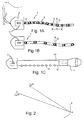
- a surface vessel 1 tows, by means of a cable 2, a sonar 3 with a deformable antenna.
- the sonar 3 comprises a head 4 and a deformable antenna 5.
- the flexible antenna 3 is formed of a plurality of N sections 6 j coupled one after the other by as many joints 7 j junction.
- Each section 6 j is provided with a transducer 8 j as well as associated low level electronics 9 j allowing the emission and / or the reception of an acoustic signal in the surrounding medium.
- the communication from the electronics 9 j of a given section 6 j to the head 4, or from the head 4 to at least one electronic 9 j of a given section 6 j is possible thanks to the presence of communication means adapted.
- these communication means are electrical cables, but, alternatively, could be optical fibers or a means of communication by electromagnetic or acoustic waves of short range between transmission / reception means on the head 4 and means of transmission.
- transmission / reception equipping each of the sections 6 j .
- the sonar 3 is in communication, rising and falling, with the surface vessel 1 via an umbilical 10.
- the head 4 of the sonar comprises only means for transmitting the information collected from the different sections 6 j to the surface vessel 1, possibly by amplifying them, and to transmit the downward signals from the surface vessel 1 to, by example, the corresponding section 6 j .
- the head 4 of the sonar 3 is also equipped with an inertial unit 11.
- the inertial unit 11 makes it possible, by measuring linear accelerations and angular speeds of rotation, to determine, at each instant, the position of the head 4: three positioning coordinates of a reference point, such as the center of gravity of the head 4, and three angular position coordinates of a reference linked to the head 4 with respect to an inertial reference frame of reference.
- each ball joint 7 j between two consecutive sections 6 j-1 and 6 j is instrumented so as to measure the three angles corresponding to the three degrees of freedom between the two sections considered.
- the various angular sensors placed at the level of the ball joints 7 j measure an instantaneous angular information, of angle or angular velocity, which is communicated, thanks to the means previously described, to the head 4 of the sonar 3.
- the ball 7 j may have less degree of freedom.
- the ball may be a pivot type connection whose axis is oriented to be substantially vertical during the use of the sonar 3.
- the number of angles and / or angular velocities instantaneous to measure is reduced.
- a pivot connection a single angle and / or a single angular velocity must be measured at each instant to know the relative position of the section 6 j relative to the section 6 j-1 .
- the information generated by the inertial unit as well as the various angular information from each ball 7 j are transmitted along the umbilical 10 to the surface vessel 1 where suitable calculation means 15 allow information processing according to a method which will be described in detail below.
- the calculation means 15 comprise a calculation unit and a storage unit.
- the storage unit stores the value of different variables or parameters as well as instructions of different programs that can be executed by the computing unit. In the most preferable embodiment, among the various stored programs, there is a program for implementing the signal processing method according to the invention.
- the inertial unit 11 makes it possible to know precisely the position, for example, of the center of gravity of the head 4 of the sonar 3 and the orientation thereof in an inertial frame originating from the center of gravity.
- a translation of known length along a direction also known to determine the position of the ball 7 1 connecting the head to the end of the head of the deformable antenna 5. From the angular information given by the sensors placed on the ball 7 1 , the instantaneous position and orientation of the section 6 1 and the transducer 8 1 are determined .
- the instantaneous position of the ball joint 7 2 is also determined .
- the angular information given by the sensors placed on the ball 72 2 to determine the instantaneous position and orientation of the section 6 2 and the transducer 8 2 , as well as the position of the ball 7 3 .
- Step by step the instantaneous position and orientation of each of the transducers are determined.
- the successive instantaneous shapes of the antenna are entirely determined.
- the time signal received by each of the sensors 8 i is then processed taking into account this succession of instantaneous shapes. Consequently, according to the invention, the instantaneous positions of the antenna are taken into account to generate the image of the seabed.
- the sonar system operates periodically. For a range of up to 300 meters, each recurrence of operation is separated by a duration about 400 milliseconds.
- the antenna first emits an acoustic pulse having a frequency typical of 100 kHz and a very short duration of the order of 10 ms. Then, during the rest of the recurrence, the antenna operates as a receiver and listens to the acoustic wave reverberated by the soil of the seabed or underwater objects. During this operation receiver, the antenna is deformed.
- Each section 6 i has slightly changed position, which influences the time signal detected by the associated transducer 8 i . It is therefore necessary to process the measured signal to separate the contributions from the source of the echo, on the one hand, and the displacement of the transducer generating said signal, on the other hand.
- each recurrence i of a series of recurrences required for the formation of a synthetic antenna and at each sensor j on the N sensors forming the flexible physical antenna, are associated a time signal S i, j (t) and a position C i, j (t), where t varies from 0 to T, where T is the duration of a recurrence.
- P M AT M ⁇ e j ⁇ M ⁇ S E
- the amplitude modulation A M is specific to the point M, whereas the phase shift ⁇ M depends on the relative position of the point emission C i, E (0), the reflection point M and the detection point C i, j (t).
- the aim of the processing is to calculate the amplitude modulation A M for each point M of the ground and to display it on a screen, to record it or any other use.
- This instantaneous phase shift is known thanks to the knowledge of the points C iE (0), C i, j (t) and M.
- the output is corrected signals in phase S ' i, j (t).
- the amplitude modulation A M is evaluated from the constructive and destructive interferences of these corrected signals in the phase S ' i, j (t).
- the Figure 1B represents a variant in which the different sections of the antenna are inserted inside a tube or sheath 15.
- This tube can be filled with a gel allowing a good transfer of the acoustic energy from the outside to the transducers or screws versa.
- the deformable antenna is flexible.
- the sensors making it possible to know the instantaneous position of the corresponding transducer are positioned near the receivers.
- the deformation of the antenna can be approximated more accurately by a polynomial form extrapolating the instantaneous positions measured by the different sensors. As a result, the number of sensors required to determine the instantaneous deformation of the antenna is reduced.
- a flute is constituted by a lower cable 16 and an upper cable 16 'fixed to a head 4.
- the various transducers are carried by the lower cable 16 serving as a support.
- a floating anchor 17 attached to the end of the flute allows, when the head is moved by traction, to stretch the flute.
- the instantaneous deformation of the antenna is determined by the use of a precise positioning means of the floating anchor 17 relative to the head 4 without the need for instrumentation of each of the transducers.
- this deformable antenna can be used on several recurrences for the formation of a synthetic antenna.
- the use of a physical antenna of great length makes it possible to increase the speed of movement of the sonar.
- the rear part of the physical antenna at the next recurrence coincides with the front part of the physical antenna at the previous recurrence.
- This partial overlap of the physical antenna between two successive recurrences makes it possible to correlate the signals obtained and to synthesize an antenna. Consequently, it is necessary that between two successive recurrences, the speed of movement of the antenna is not greater than half the length of the antenna that divides the period T of a recurrence.
- the maximum speed of movement is about 4 knots.
- the speed of movement of the antenna to make the synthesis can be increased.
- the use of such an antenna therefore makes it possible to map a site not only more precisely but also in a much shorter time.
Claims (4)
- Sonarsystem (3) mit- einer physischen Antenne (5) und- einer Recheneinheit (15),- wobei die physische Antenne (5) verformbar ist und eine Mehrzahl akustischer Empfänger (8) mit zueinander veränderbaren Positionen aufweist, wobei das System mit Positioniermitteln ausgestattet ist, die ermöglichen, in Echtzeit die momentane Position jedes der akustischen Empfänger (8j) zu bestimmen, und wobei die Recheneinheit (15) ermöglicht, ein Sonarbild unter Berücksichtigung der momentanen Position jedes der akustischen Empfänger (8j) zu rekonstruieren,- wobei das System (3) in der physischen Antenne (5) wenigstens einen akustischen Sender aufweist,
wobei das System (3) dadurch gekennzeichnet ist, daß- die physische Antenne (5) mit der Rückseite eines geschleppten Kopfes (4) verbunden ist, wobei der Kopf (4) mit einer Trägheitszentrale (11) ausgestattet ist, die geeignet ist, die momentane Position und die momentane Orientierung des Kopfes (4) zu bestimmen, und die physische Antenne (5) mit Sensoren bestückt ist, die ermöglichen, eine momentane relative Position des akustischen Senders und jedes der akustischen Empfänger (8j) in Bezug auf den Kopf (4) zu bestimmten, wobei die physische Antenne (5) aus einer Mehrzahl von mittels einer gleich großen Zahl von Gelenkverbindungen (7j) fortlaufend aneinander gekoppelten Abschnitten gebildet ist, wobei jede Gelenkverbindung (7j) instrumentiert ist, wobei die Sensoren Winkelsensoren sind, die eine momentane Winkelinformation zwischen zwei jeweiligen Abschnitten messen, und daß- die Recheneinheit (15) ermöglicht, durch Einbeziehen einer Folge wiederholten Funktionierens des Sonarsystems eine synthetische Antenne zu bilden. - Sonarsystem gemäß Anspruch 1, dadurch gekennzeichnet, daß die momentane Position eines akustischen Empfängers (8j) durch drei Positionskoordinaten und drei Orientierungswinkelkoordinaten gegeben ist.
- Sonarsystem gemäß Anspruch 1 oder Anspruch 2, dadurch gekennzeichnet, daß die physische Antenne (5) mehr als 24 akustische Empfänger (8j) aufweist und eine Länge von mehr als oder gleich 2 m hat.
- Sonarbildverfahren zum Verarbeiten einer Mehrzahl zeitlicher Signale, die jeweils am Ausgang einer Mehrzahl akustischer Empfänger (8j) einer physischen Antenne (5) bei der Erfassung der Reflexion wenigstens einer von einem akustischen Sender ausgestrahlten Welle erhalten werden, wobei die zeitlichen Signale durch eine Recheneinheit (15) gesammelt werden, die geeignet ist, das besagte Verfahren durchzuführen,
dadurch gekennzeichnet, daß- das besagte Verfahren in einem Sonarsystem (3) nach einem der vorangehenden Ansprüche durchgeführt wird, wobei die physische Antenne (5) eine verformbare Antenne ist, die einen Sender beinhaltet, wobei die physische Antenne (5) mit der Rückseite eines geschleppten Kopfes (4) verbunden ist, wobei der Kopf (4) mit einer Trägheitszentrale (11) ausgestattet ist, die geeignet ist, die momentane Position und die momentane Orientierung des Kopfes (4) zu bestimmen, und die physische Antenne (5) mit Sensoren bestückt ist, die ermöglichen, eine momentane relative Position des akustischen Senders und jedes der akustischen Empfänger (8j) in Bezug auf den Kopf (4) zu bestimmen, daß- das Verfahren einen Schritt zum Bestimmen in Echtzeit der momentanen Position jedes Empfängers der Mehrzahl akustischer Empfänger (8j) und der Position des akustischen Senders zum Zeitpunkt der Ausstrahlung, sowie einen Schritt zum zu jeder Zeit erfolgenden Ausgleichen der Phasenvariation der Phase des zeitlichen Signals aufgrund der Bewegungen des akustischen Senders und des akustischen Empfängers (8j) aufweist, wobei das Signal dergestalt gebildet wird, daß eine Mehrzahl korrigierter zeitlicher Signale bestimmt wird, und einen Schritt zum Bestimmen der Amplitudenmodulation eines abzubildenden Punkts in Abhängigkeit von konstruktiven und destruktiven Interferenzen zwischen den verschiedenen korrigierten zeitlichen Signalen aufweist, und daß- die zeitlichen Signale nicht nur jedem akustischen Empfänger (8j), sondern auch jedem wiederholten Funktionieren des Sonarsystems zugeordnet werden, um eine synthetische Antenne zu bilden.
Applications Claiming Priority (2)
| Application Number | Priority Date | Filing Date | Title |
|---|---|---|---|
| FR0653647A FR2905766B1 (fr) | 2006-09-08 | 2006-09-08 | Sonar a antenne deformable et procede associe de traitement du signal pour former une antenne synthetique |
| PCT/FR2007/051891 WO2008029068A1 (fr) | 2006-09-08 | 2007-09-07 | Sonar a antenne deformable et procede associe de traitement du signal pour former une antenne synthetique |
Publications (2)
| Publication Number | Publication Date |
|---|---|
| EP2059832A1 EP2059832A1 (de) | 2009-05-20 |
| EP2059832B1 true EP2059832B1 (de) | 2015-12-30 |
Family
ID=38038753
Family Applications (1)
| Application Number | Title | Priority Date | Filing Date |
|---|---|---|---|
| EP07823787.2A Active EP2059832B1 (de) | 2006-09-08 | 2007-09-07 | Sonar mit verformbarer antenne und entsprechendes signalverarbeitungsverfahren zur herstellung einer synthetischen antenne |
Country Status (7)
| Country | Link |
|---|---|
| US (1) | US8085618B2 (de) |
| EP (1) | EP2059832B1 (de) |
| JP (1) | JP2010502975A (de) |
| CA (1) | CA2662743A1 (de) |
| FR (1) | FR2905766B1 (de) |
| NO (1) | NO20091403L (de) |
| WO (1) | WO2008029068A1 (de) |
Families Citing this family (5)
| Publication number | Priority date | Publication date | Assignee | Title |
|---|---|---|---|---|
| CA3044970C (en) | 2011-05-06 | 2021-10-19 | Hadal, Inc. | Systems and methods for synthetic aperture sonar |
| US9529082B1 (en) | 2012-03-21 | 2016-12-27 | Hadal, Inc. | Systems and methods for bi-static or multi-static holographic navigation |
| FR3013850B1 (fr) * | 2013-11-22 | 2017-07-21 | Commissariat Energie Atomique | Procede de reconstruction d'une surface d'une piece |
| DE102015118819A1 (de) * | 2015-11-03 | 2017-05-04 | Atlas Elektronik Gmbh | Verfahren zum Ermitteln von Sonardaten und Unterwasserfahrzeug |
| DE102018212415A1 (de) | 2018-07-25 | 2019-06-13 | Atlas Elektronik Gmbh | Unterwasserantenne mit einem Auslenkungs-Messmittel sowie Verfahren zum Betreiben einer solchen Unterwasserantenne |
Citations (1)
| Publication number | Priority date | Publication date | Assignee | Title |
|---|---|---|---|---|
| FR2769372A1 (fr) * | 1997-10-07 | 1999-04-09 | Thomson Marconi Sonar Sas | Procede de correction des effets des mouvements parasites de l'antenne dans un sonar a antenne synthetique |
Family Cites Families (27)
| Publication number | Priority date | Publication date | Assignee | Title |
|---|---|---|---|---|
| US3713082A (en) * | 1971-09-01 | 1973-01-23 | Us Navy | Optical ranging system |
| US4204210A (en) * | 1972-09-15 | 1980-05-20 | The United States Of America As Represented By The Secretary Of The Air Force | Synthetic array radar command air launched missile system |
| US4088978A (en) * | 1976-09-27 | 1978-05-09 | Westinghouse Electric Corp. | Synthetic aperture side-looking sonar system |
| US4608571A (en) * | 1981-03-26 | 1986-08-26 | Luly Robert A | Collapsible parabolic reflector |
| JPH02278178A (ja) * | 1989-04-19 | 1990-11-14 | Nec Corp | えい航式パッシブソーナー装置 |
| US4930111A (en) * | 1989-06-30 | 1990-05-29 | The United States Of America As Represented By The Secretary Of The Navy | Overlap correlator synthetic aperture processor |
| FR2651950B1 (fr) * | 1989-09-08 | 1992-04-17 | Thomson Csf | Antenne hydrophonique lineaire et dispositif electronique de levee d'ambiguite droite-gauche associe a cette antenne. |
| US4987563A (en) * | 1990-02-07 | 1991-01-22 | Westinghouse Electric Corp. | Synthetic aperture minimum redundancy sonar apparatus |
| US5117400A (en) * | 1990-12-24 | 1992-05-26 | General Electric Company | Optical calibration of towed sensor array |
| US5528554A (en) * | 1992-12-01 | 1996-06-18 | Hughes Aircraft Company | Linear array lateral motion compensation method |
| FR2729041B1 (fr) * | 1994-12-28 | 1997-01-31 | Thomson Csf | Procede d'emission acoustique pour sonar |
| SE506479C2 (sv) * | 1995-03-28 | 1997-12-22 | Boliden Mineral Ab | Hagel för våtjakt samt framställning av sådana hagel |
| FR2738919B1 (fr) | 1995-09-15 | 1997-10-17 | Commissariat Energie Atomique | Procede et dispositif pour la correction de mesure spectrometrique dans le domaine de la detection de photons gamma |
| FR2738918B1 (fr) * | 1995-09-19 | 1997-12-05 | Thomson Csf | Procede d'autofocalisation pour sonar a antenne synthetique |
| FR2756931B1 (fr) * | 1996-12-10 | 1999-02-19 | Thomson Marconi Sonar Sas | Sonar lateral a antenne synthetique |
| FR2758629B1 (fr) * | 1997-01-17 | 1999-04-09 | Thomson Marconi Sonar Sas | Procede de recalage d'images sonar au moyen de sous-antennes |
| JP2000147093A (ja) * | 1998-11-13 | 2000-05-26 | Hitachi Ltd | 音響計測装置及び該装置を構成する自己位置計測機能付きケーブル |
| FR2818486B1 (fr) * | 2000-12-19 | 2004-07-23 | Thomson Marconi Sonar Sas | Antenne sonar synthetique interferometrique |
| FR2822960B3 (fr) * | 2001-03-30 | 2003-06-20 | Thomson Marconi Sonar Sas | Systeme de detection sous-marine basse frequence remorque |
| FR2843461B1 (fr) * | 2002-08-06 | 2004-09-10 | Thales Sa | Antenne sonar synthetique |
| JP4120334B2 (ja) * | 2002-09-26 | 2008-07-16 | 日本電気株式会社 | 合成開口ソーナー及びそれに用いる動揺補正方法並びにそのプログラム |
| US6847588B1 (en) * | 2004-03-16 | 2005-01-25 | L-3 Communications Corporation | Method for changing the frequency for sampling sonar wavefronts |
| US6943738B1 (en) * | 2004-05-18 | 2005-09-13 | Motorola, Inc. | Compact multiband inverted-F antenna |
| US7046582B1 (en) * | 2004-11-24 | 2006-05-16 | Raytheon Company | Method and system for synthetic aperture sonar |
| US7226328B1 (en) * | 2005-02-16 | 2007-06-05 | Raytheon Company | Extendable spar buoy sea-based communication system |
| FR2901364B1 (fr) * | 2006-05-16 | 2008-08-22 | Ixsea Soc Par Actions Simplifi | Systeme d'imagerie sonar a ouverture synthetique |
| US7835221B2 (en) * | 2006-07-06 | 2010-11-16 | Westerngeco L.L.C. | Optical methods and systems in marine seismic surveying |
-
2006
- 2006-09-08 FR FR0653647A patent/FR2905766B1/fr active Active
-
2007
- 2007-09-07 CA CA002662743A patent/CA2662743A1/fr not_active Abandoned
- 2007-09-07 JP JP2009527183A patent/JP2010502975A/ja active Pending
- 2007-09-07 US US12/440,545 patent/US8085618B2/en active Active
- 2007-09-07 WO PCT/FR2007/051891 patent/WO2008029068A1/fr active Application Filing
- 2007-09-07 EP EP07823787.2A patent/EP2059832B1/de active Active
-
2009
- 2009-04-06 NO NO20091403A patent/NO20091403L/no not_active Application Discontinuation
Patent Citations (1)
| Publication number | Priority date | Publication date | Assignee | Title |
|---|---|---|---|---|
| FR2769372A1 (fr) * | 1997-10-07 | 1999-04-09 | Thomson Marconi Sonar Sas | Procede de correction des effets des mouvements parasites de l'antenne dans un sonar a antenne synthetique |
Non-Patent Citations (1)
| Title |
|---|
| HUANG Y ET AL: "Synthetic aperture sonar movement stimation -the adaptive kalman filter approach", NEURAL NETWORKS AND SIGNAL PROCESSING, 2003. PROCEEDINGS OF THE 2003 I NTERNATIONAL CONFERENCE ON NANJING, CHINA DEC. 14-17, 2003, PISCATAWAY, NJ, USA,IEEE, vol. 1, 14 December 2003 (2003-12-14), pages 830 - 833, XP010692969, ISBN: 978-0-7803-7702-8, DOI: 10.1109/ICNNSP.2003.1279404 * |
Also Published As
| Publication number | Publication date |
|---|---|
| WO2008029068A1 (fr) | 2008-03-13 |
| US20100014385A1 (en) | 2010-01-21 |
| NO20091403L (no) | 2009-04-06 |
| JP2010502975A (ja) | 2010-01-28 |
| US8085618B2 (en) | 2011-12-27 |
| CA2662743A1 (fr) | 2008-03-13 |
| EP2059832A1 (de) | 2009-05-20 |
| FR2905766A1 (fr) | 2008-03-14 |
| FR2905766B1 (fr) | 2011-09-30 |
Similar Documents
| Publication | Publication Date | Title |
|---|---|---|
| EP0271537B1 (de) | Verfahren zur bestimmung der geometrie eines seismischen vielfach-wellengenerators | |
| EP0267840B1 (de) | Verfahren und Gerät zur Positionsbestimmung von Unterwasserobjekten mit Bezug auf das sie ziehende Schiff | |
| EP2059832B1 (de) | Sonar mit verformbarer antenne und entsprechendes signalverarbeitungsverfahren zur herstellung einer synthetischen antenne | |
| EP0555148B1 (de) | Verfahren zur Bestimmung der Fernfeldsignatur einer Anzahl seismischer Quellen | |
| FR2729041A1 (fr) | Procede d'emission acoustique pour sonar | |
| WO2015136089A1 (fr) | Sonar a antenne synthetique et procede de formation de voies d'antenne synthetique | |
| EP0133135B1 (de) | Ultraschallmultisensor mit Sensoren von verschiedenen Grössen | |
| EP0446111B1 (de) | Verfahren und Gerät zur akustischen Standortsbestimmung eines Unterwasserobjektes und Anwendung für ein Schleppnetz | |
| WO1996018116A1 (fr) | Procede de reception avec levee d'ambiguite pour une antenne acoustique lineaire remorquee | |
| FR3015052A1 (de) | ||
| EP0718638A1 (de) | Verfahren zum Entdecken von Gegenständen in der Bodenfläche oder zum Bestimmen der Ausbreitungsmerkmale einer akustischen Welle im Boden und Vorrichtung dafür | |
| EP0688437B1 (de) | Vorrichtung zum aufspüren im boden eingebetteter objekte | |
| EP1099958B1 (de) | Verfahren und Gerät zur Bestimmung der Form einer linearen Antenna und zur Auflösung der Richtungsmehrdeutigkeit | |
| FR2590032A1 (fr) | Procede de localisation acoustique d'objets sous-marins | |
| EP0458947B1 (de) | Verfahren und vorrichtung zur datenerfassung von seismischen messwerten aus bohrlöchern in zwei entgegengesetzten richtungen | |
| FR2664503A1 (fr) | Appareil pour detecter l'impact d'un projectile lance lors d'une activite sportive, notamment pour detecter l'impact d'une balle de golf. | |
| EP3195007B1 (de) | Radarverfahren zur schätzung der grösse von herabfallenden gesteinsblöcken | |
| EP0626073B1 (de) | Verfahren zur Detektion eines Unterwasserzieles unter Verwendung von Frequenzdiversität | |
| CA2129753C (fr) | Procede de stabilisation et de formation de voies pour sonar et sonar pour sa mise en oeuvre | |
| WO2018172536A1 (fr) | Dispositif de reperage par ultrasons | |
| FR2685782A1 (fr) | Procede de compensation du mouvement de l'antenne pour un sonar. | |
| WO1990000135A1 (fr) | Equipement de controle d'un emetteur d'ondes acoustiques sous-marin remorque, notamment pour le dragage des mines | |
| FR2916054A1 (fr) | Procede et dispositif de detection acoustique en milieu liquide. | |
| FR2735873A1 (fr) | Procede de mesure de vitesse a l'aide d'un loch doppler a precision amelioree |
Legal Events
| Date | Code | Title | Description |
|---|---|---|---|
| PUAI | Public reference made under article 153(3) epc to a published international application that has entered the european phase |
Free format text: ORIGINAL CODE: 0009012 |
|
| 17P | Request for examination filed |
Effective date: 20090305 |
|
| AK | Designated contracting states |
Kind code of ref document: A1 Designated state(s): AT BE BG CH CY CZ DE DK EE ES FI FR GB GR HU IE IS IT LI LT LU LV MC MT NL PL PT RO SE SI SK TR |
|
| AX | Request for extension of the european patent |
Extension state: AL BA HR MK RS |
|
| RAP1 | Party data changed (applicant data changed or rights of an application transferred) |
Owner name: IXBLUE |
|
| 17Q | First examination report despatched |
Effective date: 20110927 |
|
| DAX | Request for extension of the european patent (deleted) | ||
| GRAP | Despatch of communication of intention to grant a patent |
Free format text: ORIGINAL CODE: EPIDOSNIGR1 |
|
| RIC1 | Information provided on ipc code assigned before grant |
Ipc: G01S 15/89 20060101AFI20150820BHEP Ipc: G01S 7/521 20060101ALI20150820BHEP Ipc: G01V 1/38 20060101ALI20150820BHEP |
|
| INTG | Intention to grant announced |
Effective date: 20150901 |
|
| GRAS | Grant fee paid |
Free format text: ORIGINAL CODE: EPIDOSNIGR3 |
|
| GRAA | (expected) grant |
Free format text: ORIGINAL CODE: 0009210 |
|
| AK | Designated contracting states |
Kind code of ref document: B1 Designated state(s): AT BE BG CH CY CZ DE DK EE ES FI FR GB GR HU IE IS IT LI LT LU LV MC MT NL PL PT RO SE SI SK TR |
|
| REG | Reference to a national code |
Ref country code: GB Ref legal event code: FG4D Free format text: NOT ENGLISH |
|
| REG | Reference to a national code |
Ref country code: CH Ref legal event code: EP |
|
| REG | Reference to a national code |
Ref country code: AT Ref legal event code: REF Ref document number: 767723 Country of ref document: AT Kind code of ref document: T Effective date: 20160115 |
|
| REG | Reference to a national code |
Ref country code: IE Ref legal event code: FG4D Free format text: LANGUAGE OF EP DOCUMENT: FRENCH |
|
| REG | Reference to a national code |
Ref country code: DE Ref legal event code: R096 Ref document number: 602007044412 Country of ref document: DE |
|
| REG | Reference to a national code |
Ref country code: LT Ref legal event code: MG4D |
|
| PG25 | Lapsed in a contracting state [announced via postgrant information from national office to epo] |
Ref country code: LT Free format text: LAPSE BECAUSE OF FAILURE TO SUBMIT A TRANSLATION OF THE DESCRIPTION OR TO PAY THE FEE WITHIN THE PRESCRIBED TIME-LIMIT Effective date: 20151230 |
|
| REG | Reference to a national code |
Ref country code: NL Ref legal event code: MP Effective date: 20151230 |
|
| REG | Reference to a national code |
Ref country code: AT Ref legal event code: MK05 Ref document number: 767723 Country of ref document: AT Kind code of ref document: T Effective date: 20151230 |
|
| PG25 | Lapsed in a contracting state [announced via postgrant information from national office to epo] |
Ref country code: LV Free format text: LAPSE BECAUSE OF FAILURE TO SUBMIT A TRANSLATION OF THE DESCRIPTION OR TO PAY THE FEE WITHIN THE PRESCRIBED TIME-LIMIT Effective date: 20151230 Ref country code: GR Free format text: LAPSE BECAUSE OF FAILURE TO SUBMIT A TRANSLATION OF THE DESCRIPTION OR TO PAY THE FEE WITHIN THE PRESCRIBED TIME-LIMIT Effective date: 20160331 Ref country code: FI Free format text: LAPSE BECAUSE OF FAILURE TO SUBMIT A TRANSLATION OF THE DESCRIPTION OR TO PAY THE FEE WITHIN THE PRESCRIBED TIME-LIMIT Effective date: 20151230 Ref country code: SE Free format text: LAPSE BECAUSE OF FAILURE TO SUBMIT A TRANSLATION OF THE DESCRIPTION OR TO PAY THE FEE WITHIN THE PRESCRIBED TIME-LIMIT Effective date: 20151230 |
|
| REG | Reference to a national code |
Ref country code: FR Ref legal event code: PLFP Year of fee payment: 10 |
|
| PG25 | Lapsed in a contracting state [announced via postgrant information from national office to epo] |
Ref country code: NL Free format text: LAPSE BECAUSE OF FAILURE TO SUBMIT A TRANSLATION OF THE DESCRIPTION OR TO PAY THE FEE WITHIN THE PRESCRIBED TIME-LIMIT Effective date: 20151230 |
|
| PG25 | Lapsed in a contracting state [announced via postgrant information from national office to epo] |
Ref country code: ES Free format text: LAPSE BECAUSE OF FAILURE TO SUBMIT A TRANSLATION OF THE DESCRIPTION OR TO PAY THE FEE WITHIN THE PRESCRIBED TIME-LIMIT Effective date: 20151230 Ref country code: CZ Free format text: LAPSE BECAUSE OF FAILURE TO SUBMIT A TRANSLATION OF THE DESCRIPTION OR TO PAY THE FEE WITHIN THE PRESCRIBED TIME-LIMIT Effective date: 20151230 Ref country code: IT Free format text: LAPSE BECAUSE OF FAILURE TO SUBMIT A TRANSLATION OF THE DESCRIPTION OR TO PAY THE FEE WITHIN THE PRESCRIBED TIME-LIMIT Effective date: 20151230 |
|
| PG25 | Lapsed in a contracting state [announced via postgrant information from national office to epo] |
Ref country code: AT Free format text: LAPSE BECAUSE OF FAILURE TO SUBMIT A TRANSLATION OF THE DESCRIPTION OR TO PAY THE FEE WITHIN THE PRESCRIBED TIME-LIMIT Effective date: 20151230 Ref country code: EE Free format text: LAPSE BECAUSE OF FAILURE TO SUBMIT A TRANSLATION OF THE DESCRIPTION OR TO PAY THE FEE WITHIN THE PRESCRIBED TIME-LIMIT Effective date: 20151230 Ref country code: PL Free format text: LAPSE BECAUSE OF FAILURE TO SUBMIT A TRANSLATION OF THE DESCRIPTION OR TO PAY THE FEE WITHIN THE PRESCRIBED TIME-LIMIT Effective date: 20151230 Ref country code: IS Free format text: LAPSE BECAUSE OF FAILURE TO SUBMIT A TRANSLATION OF THE DESCRIPTION OR TO PAY THE FEE WITHIN THE PRESCRIBED TIME-LIMIT Effective date: 20160430 Ref country code: PT Free format text: LAPSE BECAUSE OF FAILURE TO SUBMIT A TRANSLATION OF THE DESCRIPTION OR TO PAY THE FEE WITHIN THE PRESCRIBED TIME-LIMIT Effective date: 20160502 Ref country code: SK Free format text: LAPSE BECAUSE OF FAILURE TO SUBMIT A TRANSLATION OF THE DESCRIPTION OR TO PAY THE FEE WITHIN THE PRESCRIBED TIME-LIMIT Effective date: 20151230 Ref country code: RO Free format text: LAPSE BECAUSE OF FAILURE TO SUBMIT A TRANSLATION OF THE DESCRIPTION OR TO PAY THE FEE WITHIN THE PRESCRIBED TIME-LIMIT Effective date: 20151230 |
|
| REG | Reference to a national code |
Ref country code: DE Ref legal event code: R097 Ref document number: 602007044412 Country of ref document: DE |
|
| PG25 | Lapsed in a contracting state [announced via postgrant information from national office to epo] |
Ref country code: DK Free format text: LAPSE BECAUSE OF FAILURE TO SUBMIT A TRANSLATION OF THE DESCRIPTION OR TO PAY THE FEE WITHIN THE PRESCRIBED TIME-LIMIT Effective date: 20151230 |
|
| PLBE | No opposition filed within time limit |
Free format text: ORIGINAL CODE: 0009261 |
|
| STAA | Information on the status of an ep patent application or granted ep patent |
Free format text: STATUS: NO OPPOSITION FILED WITHIN TIME LIMIT |
|
| 26N | No opposition filed |
Effective date: 20161003 |
|
| PG25 | Lapsed in a contracting state [announced via postgrant information from national office to epo] |
Ref country code: BE Free format text: LAPSE BECAUSE OF NON-PAYMENT OF DUE FEES Effective date: 20160930 Ref country code: SI Free format text: LAPSE BECAUSE OF FAILURE TO SUBMIT A TRANSLATION OF THE DESCRIPTION OR TO PAY THE FEE WITHIN THE PRESCRIBED TIME-LIMIT Effective date: 20151230 |
|
| PG25 | Lapsed in a contracting state [announced via postgrant information from national office to epo] |
Ref country code: MC Free format text: LAPSE BECAUSE OF FAILURE TO SUBMIT A TRANSLATION OF THE DESCRIPTION OR TO PAY THE FEE WITHIN THE PRESCRIBED TIME-LIMIT Effective date: 20151230 |
|
| REG | Reference to a national code |
Ref country code: CH Ref legal event code: PL |
|
| REG | Reference to a national code |
Ref country code: FR Ref legal event code: PLFP Year of fee payment: 11 |
|
| REG | Reference to a national code |
Ref country code: IE Ref legal event code: MM4A |
|
| PG25 | Lapsed in a contracting state [announced via postgrant information from national office to epo] |
Ref country code: LI Free format text: LAPSE BECAUSE OF NON-PAYMENT OF DUE FEES Effective date: 20160930 Ref country code: IE Free format text: LAPSE BECAUSE OF NON-PAYMENT OF DUE FEES Effective date: 20160907 Ref country code: CH Free format text: LAPSE BECAUSE OF NON-PAYMENT OF DUE FEES Effective date: 20160930 |
|
| PG25 | Lapsed in a contracting state [announced via postgrant information from national office to epo] |
Ref country code: LU Free format text: LAPSE BECAUSE OF NON-PAYMENT OF DUE FEES Effective date: 20160907 |
|
| REG | Reference to a national code |
Ref country code: BE Ref legal event code: MM Effective date: 20160930 |
|
| PG25 | Lapsed in a contracting state [announced via postgrant information from national office to epo] |
Ref country code: HU Free format text: LAPSE BECAUSE OF FAILURE TO SUBMIT A TRANSLATION OF THE DESCRIPTION OR TO PAY THE FEE WITHIN THE PRESCRIBED TIME-LIMIT; INVALID AB INITIO Effective date: 20070907 Ref country code: CY Free format text: LAPSE BECAUSE OF FAILURE TO SUBMIT A TRANSLATION OF THE DESCRIPTION OR TO PAY THE FEE WITHIN THE PRESCRIBED TIME-LIMIT Effective date: 20151230 |
|
| REG | Reference to a national code |
Ref country code: FR Ref legal event code: PLFP Year of fee payment: 12 |
|
| PG25 | Lapsed in a contracting state [announced via postgrant information from national office to epo] |
Ref country code: TR Free format text: LAPSE BECAUSE OF FAILURE TO SUBMIT A TRANSLATION OF THE DESCRIPTION OR TO PAY THE FEE WITHIN THE PRESCRIBED TIME-LIMIT Effective date: 20151230 Ref country code: MT Free format text: LAPSE BECAUSE OF FAILURE TO SUBMIT A TRANSLATION OF THE DESCRIPTION OR TO PAY THE FEE WITHIN THE PRESCRIBED TIME-LIMIT Effective date: 20151230 |
|
| PG25 | Lapsed in a contracting state [announced via postgrant information from national office to epo] |
Ref country code: BG Free format text: LAPSE BECAUSE OF FAILURE TO SUBMIT A TRANSLATION OF THE DESCRIPTION OR TO PAY THE FEE WITHIN THE PRESCRIBED TIME-LIMIT Effective date: 20151230 |
|
| REG | Reference to a national code |
Ref country code: FR Ref legal event code: PLFP Year of fee payment: 16 |
|
| P01 | Opt-out of the competence of the unified patent court (upc) registered |
Effective date: 20230524 |
|
| REG | Reference to a national code |
Ref country code: DE Ref legal event code: R081 Ref document number: 602007044412 Country of ref document: DE Owner name: EXAIL SAS, FR Free format text: FORMER OWNER: IXBLUE, MARLY LE ROI, FR |
|
| PGFP | Annual fee paid to national office [announced via postgrant information from national office to epo] |
Ref country code: GB Payment date: 20231124 Year of fee payment: 17 |
|
| PGFP | Annual fee paid to national office [announced via postgrant information from national office to epo] |
Ref country code: FR Payment date: 20231124 Year of fee payment: 17 Ref country code: DE Payment date: 20231127 Year of fee payment: 17 |