EP2059832B1 - Sonar with deformable antenna and associated method of signal processing to form a synthetic antenna - Google Patents
Sonar with deformable antenna and associated method of signal processing to form a synthetic antenna Download PDFInfo
- Publication number
- EP2059832B1 EP2059832B1 EP07823787.2A EP07823787A EP2059832B1 EP 2059832 B1 EP2059832 B1 EP 2059832B1 EP 07823787 A EP07823787 A EP 07823787A EP 2059832 B1 EP2059832 B1 EP 2059832B1
- Authority
- EP
- European Patent Office
- Prior art keywords
- antenna
- acoustic
- head
- physical antenna
- sonar
- Prior art date
- Legal status (The legal status is an assumption and is not a legal conclusion. Google has not performed a legal analysis and makes no representation as to the accuracy of the status listed.)
- Active
Links
- 238000000034 method Methods 0.000 title claims description 10
- 238000012545 processing Methods 0.000 title claims description 6
- 238000003384 imaging method Methods 0.000 claims description 3
- 230000001066 destructive effect Effects 0.000 claims description 2
- 238000001514 detection method Methods 0.000 claims description 2
- 241000251468 Actinopterygii Species 0.000 description 10
- 238000004891 communication Methods 0.000 description 7
- 230000005540 biological transmission Effects 0.000 description 5
- 230000015572 biosynthetic process Effects 0.000 description 4
- 230000010363 phase shift Effects 0.000 description 4
- 230000005484 gravity Effects 0.000 description 3
- 238000006073 displacement reaction Methods 0.000 description 2
- 238000003672 processing method Methods 0.000 description 2
- 238000003786 synthesis reaction Methods 0.000 description 2
- 230000001133 acceleration Effects 0.000 description 1
- 230000015556 catabolic process Effects 0.000 description 1
- 238000006731 degradation reaction Methods 0.000 description 1
- 230000010365 information processing Effects 0.000 description 1
- 230000003287 optical effect Effects 0.000 description 1
- 239000013307 optical fiber Substances 0.000 description 1
- 238000011160 research Methods 0.000 description 1
- 230000000630 rising effect Effects 0.000 description 1
- 239000013535 sea water Substances 0.000 description 1
- 239000002689 soil Substances 0.000 description 1
- 239000007787 solid Substances 0.000 description 1
- 230000002123 temporal effect Effects 0.000 description 1
- 238000012546 transfer Methods 0.000 description 1
- 238000013519 translation Methods 0.000 description 1
Images
Classifications
-
- G—PHYSICS
- G01—MEASURING; TESTING
- G01S—RADIO DIRECTION-FINDING; RADIO NAVIGATION; DETERMINING DISTANCE OR VELOCITY BY USE OF RADIO WAVES; LOCATING OR PRESENCE-DETECTING BY USE OF THE REFLECTION OR RERADIATION OF RADIO WAVES; ANALOGOUS ARRANGEMENTS USING OTHER WAVES
- G01S15/00—Systems using the reflection or reradiation of acoustic waves, e.g. sonar systems
- G01S15/88—Sonar systems specially adapted for specific applications
- G01S15/89—Sonar systems specially adapted for specific applications for mapping or imaging
- G01S15/8902—Side-looking sonar
- G01S15/8904—Side-looking sonar using synthetic aperture techniques
-
- G—PHYSICS
- G01—MEASURING; TESTING
- G01S—RADIO DIRECTION-FINDING; RADIO NAVIGATION; DETERMINING DISTANCE OR VELOCITY BY USE OF RADIO WAVES; LOCATING OR PRESENCE-DETECTING BY USE OF THE REFLECTION OR RERADIATION OF RADIO WAVES; ANALOGOUS ARRANGEMENTS USING OTHER WAVES
- G01S7/00—Details of systems according to groups G01S13/00, G01S15/00, G01S17/00
- G01S7/52—Details of systems according to groups G01S13/00, G01S15/00, G01S17/00 of systems according to group G01S15/00
- G01S7/521—Constructional features
-
- G—PHYSICS
- G01—MEASURING; TESTING
- G01V—GEOPHYSICS; GRAVITATIONAL MEASUREMENTS; DETECTING MASSES OR OBJECTS; TAGS
- G01V1/00—Seismology; Seismic or acoustic prospecting or detecting
- G01V1/38—Seismology; Seismic or acoustic prospecting or detecting specially adapted for water-covered areas
- G01V1/3817—Positioning of seismic devices
- G01V1/3835—Positioning of seismic devices measuring position, e.g. by GPS or acoustically
Definitions
- the subject of the present invention is that of sonar imaging in a marine environment. More particularly, the invention relates to an improved sonar and an associated method of signal processing.
- an underwater device or fish
- the flanks of the fish carry respectively sonar, said side.
- the acoustic antenna of each of these lateral sonars is formed by a row of a plurality of transducers operating in reception, associated with at least one transducer operating in transmission.
- the fish sails so that it is positioned for example at about thirty meters above the bottom to image up to a range of 300 meters. More generally, the fish sails at an altitude above the bottom which corresponds to about 10% of the maximum observation distance.
- Each lateral sonar then makes it possible to observe a strip of land that runs along parallel to the trajectory of movement of the fish and broadly, in a vertical plane transverse to the trajectory of the fish, within a sector angular sonar origin and extending generally between 30 ° and 80 ° relative to the vertical.
- the resolution of a sonar depends, at a given working frequency, essentially the length of the receiving antenna. To improve sonar resolution, it was therefore, initially, to increase the length of their antenna. But, the increase in the length of the antenna is limited by the size of the support fish. It is thus difficult to go beyond an antenna of the order of 3 m due to congestion fish on board the surface vessel, and especially difficulties in launching and recovering this fish. Different means of extending the antenna have been proposed.
- the document FR2738918 discloses a synthetic aperture sonar system which, by means of a signal processing device and method, makes it possible to have a larger virtual antenna than the physical antenna, for example about 30 m for the virtual antenna while the Physical antenna measures about 3 m.
- this device and this method lead to a limitation of the speed of the carrier which must remain less than half of the antenna length by recurrence, typically 5 nodes for 2 m antenna and 300 m range.
- the document US 5747724 discloses a sonar system for seismic surveys, the antenna of which, initially picked up within the body of an underwater traction means, can be deployed and dragged behind the traction means which can itself be towed by a surface ship.
- the antenna is constituted by a series of acoustic detectors connected to each other by a support cable.
- a telemetric housing is connected by a communication cable to the pulling means.
- This telemetry unit comprises the electronics necessary for multiplexing the signals coming from each of the acoustic detectors and retransmitting the multiplexed signal to the traction means via the communication cable.
- a floating anchor At the rear end of the antenna, on the side opposite to the traction means, a floating anchor, the drag of which is important, makes it possible to tension the antenna support cable when the traction means moves, so that the Acoustic detectors are maintained in a rigid relative position, substantially rearward, along the path of the traction means.
- each acoustic detector is animated by instantaneous movements that separate it from the trajectory followed. The consequence of these movements is a degradation of sonar properties compared to those expected, and in particular a low resolution, which may be acceptable for applications such as seismic research, where the working wavelength is order of or greater than 10 cm, but is not acceptable for lower wavelengths such as those used for side sonars.
- the subject of the invention is a sonar system according to claim 1.
- the instantaneous position of a receiver is given by three positioning coordinates and three angular orientation coordinates.
- the deformable antenna has more than 24 receivers and a length greater than or equal to 2m.
- the invention also relates to a sonar imaging method according to claim 4.
- the positions of each of the transducers of the deformable antenna are determined in real time. From this information, adapted signal processing means reconstruct an image equivalent to that which could be obtained by means of a rigid linear antenna of equivalent size.
- a surface vessel 1 tows, by means of a cable 2, a sonar 3 with a deformable antenna.
- the sonar 3 comprises a head 4 and a deformable antenna 5.
- the flexible antenna 3 is formed of a plurality of N sections 6 j coupled one after the other by as many joints 7 j junction.
- Each section 6 j is provided with a transducer 8 j as well as associated low level electronics 9 j allowing the emission and / or the reception of an acoustic signal in the surrounding medium.
- the communication from the electronics 9 j of a given section 6 j to the head 4, or from the head 4 to at least one electronic 9 j of a given section 6 j is possible thanks to the presence of communication means adapted.
- these communication means are electrical cables, but, alternatively, could be optical fibers or a means of communication by electromagnetic or acoustic waves of short range between transmission / reception means on the head 4 and means of transmission.
- transmission / reception equipping each of the sections 6 j .
- the sonar 3 is in communication, rising and falling, with the surface vessel 1 via an umbilical 10.
- the head 4 of the sonar comprises only means for transmitting the information collected from the different sections 6 j to the surface vessel 1, possibly by amplifying them, and to transmit the downward signals from the surface vessel 1 to, by example, the corresponding section 6 j .
- the head 4 of the sonar 3 is also equipped with an inertial unit 11.
- the inertial unit 11 makes it possible, by measuring linear accelerations and angular speeds of rotation, to determine, at each instant, the position of the head 4: three positioning coordinates of a reference point, such as the center of gravity of the head 4, and three angular position coordinates of a reference linked to the head 4 with respect to an inertial reference frame of reference.
- each ball joint 7 j between two consecutive sections 6 j-1 and 6 j is instrumented so as to measure the three angles corresponding to the three degrees of freedom between the two sections considered.
- the various angular sensors placed at the level of the ball joints 7 j measure an instantaneous angular information, of angle or angular velocity, which is communicated, thanks to the means previously described, to the head 4 of the sonar 3.
- the ball 7 j may have less degree of freedom.
- the ball may be a pivot type connection whose axis is oriented to be substantially vertical during the use of the sonar 3.
- the number of angles and / or angular velocities instantaneous to measure is reduced.
- a pivot connection a single angle and / or a single angular velocity must be measured at each instant to know the relative position of the section 6 j relative to the section 6 j-1 .
- the information generated by the inertial unit as well as the various angular information from each ball 7 j are transmitted along the umbilical 10 to the surface vessel 1 where suitable calculation means 15 allow information processing according to a method which will be described in detail below.
- the calculation means 15 comprise a calculation unit and a storage unit.
- the storage unit stores the value of different variables or parameters as well as instructions of different programs that can be executed by the computing unit. In the most preferable embodiment, among the various stored programs, there is a program for implementing the signal processing method according to the invention.
- the inertial unit 11 makes it possible to know precisely the position, for example, of the center of gravity of the head 4 of the sonar 3 and the orientation thereof in an inertial frame originating from the center of gravity.
- a translation of known length along a direction also known to determine the position of the ball 7 1 connecting the head to the end of the head of the deformable antenna 5. From the angular information given by the sensors placed on the ball 7 1 , the instantaneous position and orientation of the section 6 1 and the transducer 8 1 are determined .
- the instantaneous position of the ball joint 7 2 is also determined .
- the angular information given by the sensors placed on the ball 72 2 to determine the instantaneous position and orientation of the section 6 2 and the transducer 8 2 , as well as the position of the ball 7 3 .
- Step by step the instantaneous position and orientation of each of the transducers are determined.
- the successive instantaneous shapes of the antenna are entirely determined.
- the time signal received by each of the sensors 8 i is then processed taking into account this succession of instantaneous shapes. Consequently, according to the invention, the instantaneous positions of the antenna are taken into account to generate the image of the seabed.
- the sonar system operates periodically. For a range of up to 300 meters, each recurrence of operation is separated by a duration about 400 milliseconds.
- the antenna first emits an acoustic pulse having a frequency typical of 100 kHz and a very short duration of the order of 10 ms. Then, during the rest of the recurrence, the antenna operates as a receiver and listens to the acoustic wave reverberated by the soil of the seabed or underwater objects. During this operation receiver, the antenna is deformed.
- Each section 6 i has slightly changed position, which influences the time signal detected by the associated transducer 8 i . It is therefore necessary to process the measured signal to separate the contributions from the source of the echo, on the one hand, and the displacement of the transducer generating said signal, on the other hand.
- each recurrence i of a series of recurrences required for the formation of a synthetic antenna and at each sensor j on the N sensors forming the flexible physical antenna, are associated a time signal S i, j (t) and a position C i, j (t), where t varies from 0 to T, where T is the duration of a recurrence.
- P M AT M ⁇ e j ⁇ M ⁇ S E
- the amplitude modulation A M is specific to the point M, whereas the phase shift ⁇ M depends on the relative position of the point emission C i, E (0), the reflection point M and the detection point C i, j (t).
- the aim of the processing is to calculate the amplitude modulation A M for each point M of the ground and to display it on a screen, to record it or any other use.
- This instantaneous phase shift is known thanks to the knowledge of the points C iE (0), C i, j (t) and M.
- the output is corrected signals in phase S ' i, j (t).
- the amplitude modulation A M is evaluated from the constructive and destructive interferences of these corrected signals in the phase S ' i, j (t).
- the Figure 1B represents a variant in which the different sections of the antenna are inserted inside a tube or sheath 15.
- This tube can be filled with a gel allowing a good transfer of the acoustic energy from the outside to the transducers or screws versa.
- the deformable antenna is flexible.
- the sensors making it possible to know the instantaneous position of the corresponding transducer are positioned near the receivers.
- the deformation of the antenna can be approximated more accurately by a polynomial form extrapolating the instantaneous positions measured by the different sensors. As a result, the number of sensors required to determine the instantaneous deformation of the antenna is reduced.
- a flute is constituted by a lower cable 16 and an upper cable 16 'fixed to a head 4.
- the various transducers are carried by the lower cable 16 serving as a support.
- a floating anchor 17 attached to the end of the flute allows, when the head is moved by traction, to stretch the flute.
- the instantaneous deformation of the antenna is determined by the use of a precise positioning means of the floating anchor 17 relative to the head 4 without the need for instrumentation of each of the transducers.
- this deformable antenna can be used on several recurrences for the formation of a synthetic antenna.
- the use of a physical antenna of great length makes it possible to increase the speed of movement of the sonar.
- the rear part of the physical antenna at the next recurrence coincides with the front part of the physical antenna at the previous recurrence.
- This partial overlap of the physical antenna between two successive recurrences makes it possible to correlate the signals obtained and to synthesize an antenna. Consequently, it is necessary that between two successive recurrences, the speed of movement of the antenna is not greater than half the length of the antenna that divides the period T of a recurrence.
- the maximum speed of movement is about 4 knots.
- the speed of movement of the antenna to make the synthesis can be increased.
- the use of such an antenna therefore makes it possible to map a site not only more precisely but also in a much shorter time.
Description
La présente invention a pour domaine celui de l'imagerie sonar en milieu marin. Plus particulièrement, l'invention porte sur un sonar amélioré et un procédé associé de traitement du signal.The subject of the present invention is that of sonar imaging in a marine environment. More particularly, the invention relates to an improved sonar and an associated method of signal processing.
Il est connu « d'éclairer » le fond marin dont on souhaite obtenir une image ou une cible sous-marine que l'on souhaite repérer avec une impulsion acoustique, puis d'écouter le signal temporel généré par la réverbération de l'impulsion acoustique émise.It is known "to illuminate" the seabed which is desired to obtain an underwater image or target that is to be identified with an acoustic pulse, then to listen to the temporal signal generated by the reverberation of the acoustic pulse issued.
Pour cela, il est connu d'utiliser un appareil sous-marin, ou poisson, tracté par un bâtiment de surface. Les flancs du poisson portent respectivement des sonars, dit latéraux. L'antenne acoustique de chacun des ces sonars latéraux est formée par une rangée d'une pluralité de transducteurs fonctionnant en réception, associés à au moins un transducteur fonctionnant en émission. Lors d'une plongée pour réaliser une image d'un fond marin, le poisson navigue de telle sorte qu'il soit positionné par exemple à une trentaine de mètres au dessus du fond pour imager jusqu'à une portée de 300 mètres. De façon plus générale, le poisson navigue à une altitude au dessus du fond qui correspond à environ 10% de la distance maximale d'observation. Chaque sonar latéral permet alors l'observation d'une bande de terrain qui se défile en long parallèlement à la trajectoire de déplacement du poisson et en large, dans un plan vertical transversal à la trajectoire du poisson, à l'intérieure d'un secteur angulaire ayant pour origine le sonar et s'étendant généralement entre 30° et 80° par rapport à la verticale.For this, it is known to use an underwater device, or fish, towed by a surface vessel. The flanks of the fish carry respectively sonar, said side. The acoustic antenna of each of these lateral sonars is formed by a row of a plurality of transducers operating in reception, associated with at least one transducer operating in transmission. During a dive to make an image of a seabed, the fish sails so that it is positioned for example at about thirty meters above the bottom to image up to a range of 300 meters. More generally, the fish sails at an altitude above the bottom which corresponds to about 10% of the maximum observation distance. Each lateral sonar then makes it possible to observe a strip of land that runs along parallel to the trajectory of movement of the fish and broadly, in a vertical plane transverse to the trajectory of the fish, within a sector angular sonar origin and extending generally between 30 ° and 80 ° relative to the vertical.
Or, la résolution d'un sonar dépend, à une fréquence de travail donnée, essentiellement de la longueur de l'antenne de réception. Pour améliorer la résolution des sonars, il s'est donc agit, dans un premier temps, d'augmenter la longueur de leur antenne. Mais, l'augmentation de la longueur de l'antenne est limitée par la taille du poisson support. Il est ainsi difficile d'aller au-delà d'une antenne de l'ordre de 3 m du fait de l'encombrement du poisson à bord du navire de surface, et surtout des difficultés de mise à l'eau et de récupération de ce poisson. Différents moyens d'allongement de l'antenne ont donc été proposés.However, the resolution of a sonar depends, at a given working frequency, essentially the length of the receiving antenna. To improve sonar resolution, it was therefore, initially, to increase the length of their antenna. But, the increase in the length of the antenna is limited by the size of the support fish. It is thus difficult to go beyond an antenna of the order of 3 m due to congestion fish on board the surface vessel, and especially difficulties in launching and recovering this fish. Different means of extending the antenna have been proposed.
Le document
Cependant, ce dispositif et ce procédé conduisent à une limitation de la vitesse du porteur qui doit rester inférieure à la moitié de la longueur d'antenne par récurrence, typiquement 5 noeuds pour 2 m d'antenne et 300 m de portée.However, this device and this method lead to a limitation of the speed of the carrier which must remain less than half of the antenna length by recurrence, typically 5 nodes for 2 m antenna and 300 m range.
Ainsi, le document
Le document
Cependant, lors du déplacement du moyen de traction le long d'une trajectoire, l'antenne décrite ne peut être considérée comme un solide. Cette antenne n'a pas réellement une forme rectiligne constante au cours du temps, contrairement à l'hypothèse qui est faite dans le document
On connaît également par
L'intérêt d'un sonar à antenne déformable étant reconnu, Il y a donc un besoin d'un tel système sonar à antenne déformable amélioré permettant de résoudre les problèmes mentionnés ci-dessus et en particulier permettant effectivement d'atteindre de grandes résolutions.The interest of a deformable antenna sonar being recognized, there is therefore a need for such an improved deformable antenna sonar system to solve the problems mentioned above and in particular to actually achieve high resolutions.
Pour cela l'invention a pour objet un système sonar selon la revendication 1.For this, the subject of the invention is a sonar system according to
Dans un mode de réalisation la position instantanée d'un récepteur est donnée par trois coordonnées de positionnement et trois coordonnées angulaires d'orientation.In one embodiment, the instantaneous position of a receiver is given by three positioning coordinates and three angular orientation coordinates.
De préférence l'antenne déformable comporte plus de 24 récepteurs et à une longueur supérieure ou égale à 2m.Preferably the deformable antenna has more than 24 receivers and a length greater than or equal to 2m.
L'invention a également pour objet un procédé d'imagerie sonar selon la revendication 4.The invention also relates to a sonar imaging method according to claim 4.
Avantageusement, selon la présente invention, les positions de chacun des transducteurs de l'antenne déformable sont déterminées en temps réel. A partir de ces informations, des moyens de traitement du signal adaptés reconstruisent une image équivalente à celle que l'on pourrait obtenir au moyen d'une antenne linaire rigide d'une taille équivalente.Advantageously, according to the present invention, the positions of each of the transducers of the deformable antenna are determined in real time. From this information, adapted signal processing means reconstruct an image equivalent to that which could be obtained by means of a rigid linear antenna of equivalent size.
L'invention sera mieux comprise et d'autres buts, détails, caractéristiques et avantages de celle-ci apparaîtront plus clairement au cours de la description d'un mode de réalisation particulier de l'invention donné uniquement à titre illustratif et non limitatif en référence aux dessins annexés. Sur ces dessins :
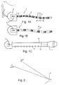
- Les
Figures 1A-C sont des représentations schématiques de la partie matérielle du système sonar selon l'invention dans trois modes de réalisations différents ; - La
figure 2 est une représentation géométrique de la situation physique prise en compte par le procédé de traitement du signal selon l'invention ;
- The
Figures 1A-C are schematic representations of the hardware part of the sonar system according to the invention in three different embodiments; - The
figure 2 is a geometric representation of the physical situation taken into account by the signal processing method according to the invention;
Comme cela est représenté sur la
Selon le premier mode de réalisation représenté sur la
Le sonar 3 est en communication, montante et descendante, avec le navire de surface 1 via un ombilical 10. Dans ce cas, la tête 4 du sonar ne comporte que des moyens permettant d'émettre les informations collectées depuis les différentes sections 6j vers le navire de surface 1, éventuellement en les amplifiant, et d'émettre les signaux descendants depuis le navire de surface 1 vers, par exemple, la section 6j correspondante.The sonar 3 is in communication, rising and falling, with the
Dans ce premier mode de réalisation, la tête 4 du sonar 3 est également équipée d'une centrale inertielle 11. La centrale inertielle 11 permet, en mesurant des accélérations linéaires et des vitesses angulaires de rotation, la détermination, à chaque instant, la position de la tête 4 : trois coordonnées de positionnement d'un point de référence, tel que le centre de gravité de la tête 4, et trois coordonnées angulaire d'attitude d'un repère lié à la tête 4 par rapport à un référentiel inertiel de référence.In this first embodiment, the head 4 of the sonar 3 is also equipped with an
Par ailleurs, chaque rotule 7j entre deux sections 6j-1 et 6j consécutives est instrumentée de manière à mesurer les trois angles correspondant aux trois degrés de liberté entre les deux sections considérées. Les différents capteurs angulaires placés au niveau des rotules 7j mesurent une information angulaire instantanée, d'angle ou de vitesse angulaire, qui est communiquée, grâce au moyen décrit précédemment, vers la tête 4 du sonar 3.Moreover, each ball joint 7 j between two consecutive sections 6 j-1 and 6 j is instrumented so as to measure the three angles corresponding to the three degrees of freedom between the two sections considered. The various angular sensors placed at the level of the ball joints 7 j measure an instantaneous angular information, of angle or angular velocity, which is communicated, thanks to the means previously described, to the head 4 of the sonar 3.
On notera que, dans des variantes de réalisation, la rotule 7j peut avoir moins de degré de liberté. Par exemple, la rotule peut être une liaison de type pivot dont l'axe est orienté pour être sensiblement verticale au cours de l'utilisation du sonar 3. En conséquence de quoi, le nombre d'angles et/ou de vitesses angulaires instantanés à mesurer est réduit. Par exemple, dans le cas d'une liaison pivot, un unique angle et/ou une unique vitesse angulaire doit être mesuré à chaque instant pour connaître le position relative de la section 6j par rapport à la section 6j-1.It will be noted that, in alternative embodiments, the ball 7 j may have less degree of freedom. For example, the ball may be a pivot type connection whose axis is oriented to be substantially vertical during the use of the sonar 3. As a result, the number of angles and / or angular velocities instantaneous to measure is reduced. For example, in the case of a pivot connection, a single angle and / or a single angular velocity must be measured at each instant to know the relative position of the section 6 j relative to the section 6 j-1 .
Les informations générées par la centrale inertielle ainsi que les différentes informations angulaires provenant de chaque rotule 7j sont transmises le long de l'ombilical 10 vers le bateau de surface 1 où des moyens de calcul adaptés 15 permettent un traitement de l'information selon un procédé qui va être décrit en détail ci-après.The information generated by the inertial unit as well as the various angular information from each ball 7 j are transmitted along the umbilical 10 to the
Les moyens de calcul 15 comportent une unité de calcul et une unité de mémorisation. L'unité de mémorisation stocke la valeur de différentes variables ou paramètres ainsi que des instructions de différents programmes aptes à être exécutées par l'unité de calcul. Dans le mode de réalisation le plus préférable, parmi les différents programmes mémorisés, il existe un programme permettant une mise oeuvre de la méthode de traitement du signal selon l'invention.The calculation means 15 comprise a calculation unit and a storage unit. The storage unit stores the value of different variables or parameters as well as instructions of different programs that can be executed by the computing unit. In the most preferable embodiment, among the various stored programs, there is a program for implementing the signal processing method according to the invention.
De manière simplifiée, on comprend que la centrale inertielle 11 permet de connaître précisément la position par exemple du centre de gravité de la tête 4 du sonar 3 et l'orientation de celle-ci dans un repère inertiel ayant pour origine le centre de gravité. Une translation d'une longueur connue le long d'une direction également connue permet de déterminer la position de la rotule 71 reliant la tête à l'extrémité côté tête de l'antenne déformable 5. A partir des informations angulaires données par les capteurs placés sur la rotule 71, on détermine la position et l'orientation instantanées de la section 61 et du transducteur 81. On détermine également la position instantanée de la rotule 72. De manière itérative, les informations angulaires données par les capteurs placés sur la rotule 72 permettent de déterminer la position et l'orientation instantanées de la section 62 et du transducteur 82, ainsi que la position de la rotule 73. De proche en proche, la position et l'orientation instantanées de chacun des transducteurs sont déterminées.In a simplified way, it is understood that the
Ainsi, au cours de la réception du signal d'écho réfléchi par un relief du fond marin par exemple, les formes instantanées successives de l'antenne sont entièrement déterminées. Le signal temporel reçu par chacun des capteurs 8i est alors traité compte tenu de cette succession de formes instantanées. En conséquence, selon l'invention, on prend en compte les positions instantanés de l'antenne pour générer l'image du fond marin.Thus, during the reception of the echo signal reflected by a relief of the seabed for example, the successive instantaneous shapes of the antenna are entirely determined. The time signal received by each of the sensors 8 i is then processed taking into account this succession of instantaneous shapes. Consequently, according to the invention, the instantaneous positions of the antenna are taken into account to generate the image of the seabed.
De manière plus détaillée, le système sonar fonctionne de manière périodique. Pour une portée maximale de 300 mètres, chaque récurrence de fonctionnement est séparée par une durée d'environ 400 millisecondes. Au cours d'une récurrence, l'antenne émet d'abord un pulse acoustique ayant une fréquence typique de 100 kHz et une durée très courte de l'ordre de 10 ms. Puis, pendant le reste de la récurrence, l'antenne fonctionne en récepteur et écoute l'onde acoustique réverbérée par le sol du fond marin ou des objets sous-marins. Pendant ce fonctionnement en récepteur, l'antenne se déforme. Chaque section 6i a légèrement changée de position, ce qui influe sur le signal temporel détecté par le transducteur 8i associé. Il faut donc traiter le signal mesuré pour séparer les contributions provenant de la source de l'écho, d'une part, et du déplacement du transducteur générant ledit signal, d'autre part.In more detail, the sonar system operates periodically. For a range of up to 300 meters, each recurrence of operation is separated by a duration about 400 milliseconds. During a recurrence, the antenna first emits an acoustic pulse having a frequency typical of 100 kHz and a very short duration of the order of 10 ms. Then, during the rest of the recurrence, the antenna operates as a receiver and listens to the acoustic wave reverberated by the soil of the seabed or underwater objects. During this operation receiver, the antenna is deformed. Each section 6 i has slightly changed position, which influences the time signal detected by the associated transducer 8 i . It is therefore necessary to process the measured signal to separate the contributions from the source of the echo, on the one hand, and the displacement of the transducer generating said signal, on the other hand.
A chaque récurrence i d'une série de R récurrences requises pour la formation d'une antenne synthétique, et à chaque capteur j sur les N capteurs formant l'antenne physique souple, sont associés un signal temporel Si,j(t) et une position Ci,j(t), où t varie de 0 à T, ou T est la durée d'une récurrence.At each recurrence i of a series of recurrences required for the formation of a synthetic antenna, and at each sensor j on the N sensors forming the flexible physical antenna, are associated a time signal S i, j (t) and a position C i, j (t), where t varies from 0 to T, where T is the duration of a recurrence.
Le signal Si,j(t) est la somme de toutes les contributions de la partie du fond marin insonifiée : ![]()
![]()
![]()
![]()
La contribution PM de chaque point M est principalement un déphasage et une modulation d'amplitude du signal émis SE : ![]()
![]()
La modulation d'amplitude AM est spécifique au point M, alors que le déphasage ϕM dépend de la position relative du point d'émission Ci,E(0), du point de réflexion M et du point de détection Ci,j(t).The amplitude modulation A M is specific to the point M, whereas the phase shift φ M depends on the relative position of the point emission C i, E (0), the reflection point M and the detection point C i, j (t).
Le traitement a pour but de calculer la modulation d'amplitude AM pour chaque point M du sol et de l'afficher sur un écran, de l'enregistrer ou tout autre utilisation. Pour cela, on corrige d'abord en phase chaque signal Si,j(t) en compensant le déphasage, qui est une fonction du temps, généré par le trajet du signal entre la position de l'émetteur à l'instant de l'émission et la position du détecteur j à l'instant t. Ce déphasage instantané est connu grâce à la connaissance des points CiE(0), Ci,j(t) et M. On obtient en sortie des signaux corrigés en phase S'i,j(t).The aim of the processing is to calculate the amplitude modulation A M for each point M of the ground and to display it on a screen, to record it or any other use. For this, first corrects each phase signal S i, j (t) by compensating the phase shift, which is a function of time, generated by the path of the signal between the position of the transmitter at the instant of transmission. emission and the position of the detector j at time t. This instantaneous phase shift is known thanks to the knowledge of the points C iE (0), C i, j (t) and M. The output is corrected signals in phase S ' i, j (t).
Puis, dans un second temps, on évalue la modulation d'amplitude AM à partir des interférences constructives et destructives de ces signaux corrigés en phase S'i,j(t).Then, in a second step, the amplitude modulation A M is evaluated from the constructive and destructive interferences of these corrected signals in the phase S ' i, j (t).
Bien que l'invention ait été décrite en référence à un mode de réalisation particulier, elle n'est nullement limitée à ce mode de réalisation. Elle comprend tous les équivalents techniques des moyens décrits ainsi que leurs combinaisons qui entrent dans le cadre de l'invention.Although the invention has been described with reference to a particular embodiment, it is not limited to this embodiment. It includes all the technical equivalents of the means described as well as their combinations which come within the scope of the invention.
Ainsi, la
Sur la
Bien évidemment, cette antenne déformable peut être utilisée sur plusieurs récurrences pour la formation d'une antenne synthétique. En particulier, l'utilisation d'une antenne physique de grande longueur permet d'augmenter la vitesse de déplacement du sonar. En effet, dans la synthèse d'antenne, il faut que la partie arrière de l'antenne physique à la récurrence suivante coïncide avec la partie avant de l'antenne physique à la récurrence précédente. Ce recouvrement partiel de l'antenne physique entre deux récurrences successives permet de corréler les signaux obtenus et de synthétiser une antenne. En conséquence, il faut qu'entre deux récurrences successives, la vitesse de déplacement de l'antenne ne soit pas supérieure à la moitié de la longueur de l'antenne que divise la période T d'une récurrence. Au moyen des antennes de l'art antérieur, la vitesse maximale de déplacement est d'environ 4 noeuds. Selon l'invention, en mettant à disposition des antennes physiques ayant de grandes dimensions, la vitesse de déplacement de l'antenne pour faire de la synthèse peut être augmentée. L'utilisation d'une telle antenne permet donc de réaliser la cartographie d'un site non seulement de manière pus précise mais également en un temps beaucoup plus court.Of course, this deformable antenna can be used on several recurrences for the formation of a synthetic antenna. In particular, the use of a physical antenna of great length makes it possible to increase the speed of movement of the sonar. Indeed, in the antenna synthesis, it is necessary that the rear part of the physical antenna at the next recurrence coincides with the front part of the physical antenna at the previous recurrence. This partial overlap of the physical antenna between two successive recurrences makes it possible to correlate the signals obtained and to synthesize an antenna. Consequently, it is necessary that between two successive recurrences, the speed of movement of the antenna is not greater than half the length of the antenna that divides the period T of a recurrence. Using antennas of the prior art, the maximum speed of movement is about 4 knots. According to the invention, by providing physical antennas having large dimensions, the speed of movement of the antenna to make the synthesis can be increased. The use of such an antenna therefore makes it possible to map a site not only more precisely but also in a much shorter time.
Claims (4)
- A sonar system (3) comprising:- a physical antenna (5) ; and- a calculation unit (15);
said physical antenna (5) being deformable and comprising a plurality of acoustic receivers (8j) having variable positions relative to each other, said system (3) being equipped with positioning means making it possible to determine, in real time, the instantaneous position of each of the acoustic receivers (8j), and said calculation unit (15) making it possible to reconstruct a sonar image by taking account of instantaneous positions of each acoustic receiver (8j),
the system (3) comprising at least one acoustic transmitter inside the physical antenna (5); the system (3) being characterized in that- the physical antenna (5) is connected to the rear of a towed head (4), said head (4) being provided with an inertial unit (11) adapted to determine the instantaneous position and orientation of said head (4) and in that the physical antenna (5) is equipped with sensors making it possible to determine a relative instantaneous position of the acoustic transmitter and of each acoustic receiver (8j) with respect to the head, the physical antenna (5) being formed of a plurality of sections coupled one after the other by as many ball joints (7j), each ball joint (7j) being instrumented, said sensors being angular sensors measuring an instantaneous angular information between two considered sections, and in that- said calculation unit (15) makes it possible to form a synthetic antenna by considering a succession of operation recurrences of the sonar system (3). - The system according to claim 1, characterized in that said instantaneous position of an acoustic receiver (8j) is given by three positioning coordinates and three angular orientation coordinates.
- The system according to claim 1 or claim 2, characterized in that said physical antenna (5) includes more than 24 acoustic receivers (8j) and has a length greater than or equal to 2 meters.
- Method of sonar imaging for processing a plurality of time signals obtained at the output of a plurality of acoustic receivers (8j) of a physical antenna (5) during the detection of the reflection of at least one wave emitted by an acoustic transmitter, said time signals being collected by a calculation unit (15) adapted to implement said method,
characterized in that- said method is implemented in a sonar system (3) according to any one of the preceding claims, said physical antenna (5) being a deformable antenna including at least one acoustic transmitter, said physical antenna (5) being connected to the rear of a towed head (4), said head (4) being provided with an inertial unit (11) adapted to determine the instantaneous position and orientation of said head (4) and the physical antenna (5) being equipped with sensors making it possible to determine a relative instantaneous position of the acoustic transmitter and of each acoustic receiver (8j) with respect to the head (4); and in that- said method comprises a step of determining, in real time, the instantaneous position of each receiver of said plurality of acoustic receivers (8j) and the position of said acoustic transmitter at the time of emission, then a step of compensating, at each instant of time, the phase of each time signal for the phase variation due to the movements of the acoustic transmitter and of the acoustic receiver (8j) generating said signal, so as to determine a plurality or corrected time signals, and a step of determining the amplitude modulation of a point to be imaged according to the mutual constructive and destructive interferences of the different corrected time signals, and in that- said time signals are associated not only with each acoustic receiver (8j), but also with each operation recurrence of the sonar system, whereby a synthetic antenna is formed.
Applications Claiming Priority (2)
| Application Number | Priority Date | Filing Date | Title |
|---|---|---|---|
| FR0653647A FR2905766B1 (en) | 2006-09-08 | 2006-09-08 | DEFORMABLE ANTENNA SONAR AND ASSOCIATED SIGNAL PROCESSING METHOD FOR FORMING SYNTHETIC ANTENNA |
| PCT/FR2007/051891 WO2008029068A1 (en) | 2006-09-08 | 2007-09-07 | Sonar with deformable antenna and associated method of signal processing to form a synthetic antenna |
Publications (2)
| Publication Number | Publication Date |
|---|---|
| EP2059832A1 EP2059832A1 (en) | 2009-05-20 |
| EP2059832B1 true EP2059832B1 (en) | 2015-12-30 |
Family
ID=38038753
Family Applications (1)
| Application Number | Title | Priority Date | Filing Date |
|---|---|---|---|
| EP07823787.2A Active EP2059832B1 (en) | 2006-09-08 | 2007-09-07 | Sonar with deformable antenna and associated method of signal processing to form a synthetic antenna |
Country Status (7)
| Country | Link |
|---|---|
| US (1) | US8085618B2 (en) |
| EP (1) | EP2059832B1 (en) |
| JP (1) | JP2010502975A (en) |
| CA (1) | CA2662743A1 (en) |
| FR (1) | FR2905766B1 (en) |
| NO (1) | NO20091403L (en) |
| WO (1) | WO2008029068A1 (en) |
Families Citing this family (5)
| Publication number | Priority date | Publication date | Assignee | Title |
|---|---|---|---|---|
| CA3044964C (en) | 2011-05-06 | 2021-11-23 | Hadal, Inc. | Systems and methods for synthetic aperture sonar |
| US9529082B1 (en) | 2012-03-21 | 2016-12-27 | Hadal, Inc. | Systems and methods for bi-static or multi-static holographic navigation |
| FR3013850B1 (en) * | 2013-11-22 | 2017-07-21 | Commissariat Energie Atomique | METHOD FOR RECONSTRUCTING A SURFACE OF A PIECE |
| DE102015118819A1 (en) * | 2015-11-03 | 2017-05-04 | Atlas Elektronik Gmbh | Method for determining sonar data and underwater vehicle |
| DE102018212415A1 (en) | 2018-07-25 | 2019-06-13 | Atlas Elektronik Gmbh | Underwater antenna with a deflection measuring means and method for operating such an underwater antenna |
Citations (1)
| Publication number | Priority date | Publication date | Assignee | Title |
|---|---|---|---|---|
| FR2769372A1 (en) * | 1997-10-07 | 1999-04-09 | Thomson Marconi Sonar Sas | Method of correction of parasitic movements of sonar antenna |
Family Cites Families (27)
| Publication number | Priority date | Publication date | Assignee | Title |
|---|---|---|---|---|
| US3713082A (en) * | 1971-09-01 | 1973-01-23 | Us Navy | Optical ranging system |
| US4204210A (en) * | 1972-09-15 | 1980-05-20 | The United States Of America As Represented By The Secretary Of The Air Force | Synthetic array radar command air launched missile system |
| US4088978A (en) * | 1976-09-27 | 1978-05-09 | Westinghouse Electric Corp. | Synthetic aperture side-looking sonar system |
| US4608571A (en) * | 1981-03-26 | 1986-08-26 | Luly Robert A | Collapsible parabolic reflector |
| JPH02278178A (en) * | 1989-04-19 | 1990-11-14 | Nec Corp | Towing type passive sonar apparatus |
| US4930111A (en) * | 1989-06-30 | 1990-05-29 | The United States Of America As Represented By The Secretary Of The Navy | Overlap correlator synthetic aperture processor |
| FR2651950B1 (en) * | 1989-09-08 | 1992-04-17 | Thomson Csf | LINEAR HYDROPHONIC ANTENNA AND ELECTRONIC RIGHT-LEFT AMBIGUITY LIFTING DEVICE ASSOCIATED WITH THIS ANTENNA. |
| US4987563A (en) * | 1990-02-07 | 1991-01-22 | Westinghouse Electric Corp. | Synthetic aperture minimum redundancy sonar apparatus |
| US5117400A (en) * | 1990-12-24 | 1992-05-26 | General Electric Company | Optical calibration of towed sensor array |
| US5528554A (en) * | 1992-12-01 | 1996-06-18 | Hughes Aircraft Company | Linear array lateral motion compensation method |
| FR2729041B1 (en) * | 1994-12-28 | 1997-01-31 | Thomson Csf | ACOUSTIC TRANSMISSION PROCESS FOR SONAR |
| SE506479C2 (en) | 1995-03-28 | 1997-12-22 | Boliden Mineral Ab | Hail for wet hunting and the production of such hail |
| FR2738919B1 (en) | 1995-09-15 | 1997-10-17 | Commissariat Energie Atomique | METHOD AND DEVICE FOR THE CORRECTION OF SPECTROMETRIC MEASUREMENT IN THE FIELD OF GAMMA PHOTON DETECTION |
| FR2738918B1 (en) * | 1995-09-19 | 1997-12-05 | Thomson Csf | SELF-FOCUSING METHOD FOR SYNTHETIC ANTENNA SONAR |
| FR2756931B1 (en) * | 1996-12-10 | 1999-02-19 | Thomson Marconi Sonar Sas | LATERAL SONAR WITH SYNTHETIC ANTENNA |
| FR2758629B1 (en) * | 1997-01-17 | 1999-04-09 | Thomson Marconi Sonar Sas | METHOD OF RECORDING SONAR IMAGES USING SUB-ANTENNAS |
| JP2000147093A (en) * | 1998-11-13 | 2000-05-26 | Hitachi Ltd | Acoustic measuring apparatus and cable with self- positioning measuring function constituting the same |
| FR2818486B1 (en) * | 2000-12-19 | 2004-07-23 | Thomson Marconi Sonar Sas | SYNTHETIC INTERFEROMETRIC SONAR ANTENNA |
| FR2822960B3 (en) * | 2001-03-30 | 2003-06-20 | Thomson Marconi Sonar Sas | LOW FREQUENCY UNDERWATER DETECTION SYSTEM |
| FR2843461B1 (en) * | 2002-08-06 | 2004-09-10 | Thales Sa | SYNTHETIC SONAR ANTENNA |
| JP4120334B2 (en) * | 2002-09-26 | 2008-07-16 | 日本電気株式会社 | Synthetic aperture sonar, shake correction method and program therefor |
| US6847588B1 (en) * | 2004-03-16 | 2005-01-25 | L-3 Communications Corporation | Method for changing the frequency for sampling sonar wavefronts |
| US6943738B1 (en) * | 2004-05-18 | 2005-09-13 | Motorola, Inc. | Compact multiband inverted-F antenna |
| US7046582B1 (en) * | 2004-11-24 | 2006-05-16 | Raytheon Company | Method and system for synthetic aperture sonar |
| US7226328B1 (en) * | 2005-02-16 | 2007-06-05 | Raytheon Company | Extendable spar buoy sea-based communication system |
| FR2901364B1 (en) * | 2006-05-16 | 2008-08-22 | Ixsea Soc Par Actions Simplifi | SONAR IMAGING SYSTEM WITH SYNTHETIC OPENING |
| US7835221B2 (en) * | 2006-07-06 | 2010-11-16 | Westerngeco L.L.C. | Optical methods and systems in marine seismic surveying |
-
2006
- 2006-09-08 FR FR0653647A patent/FR2905766B1/en active Active
-
2007
- 2007-09-07 CA CA002662743A patent/CA2662743A1/en not_active Abandoned
- 2007-09-07 WO PCT/FR2007/051891 patent/WO2008029068A1/en active Application Filing
- 2007-09-07 US US12/440,545 patent/US8085618B2/en active Active
- 2007-09-07 EP EP07823787.2A patent/EP2059832B1/en active Active
- 2007-09-07 JP JP2009527183A patent/JP2010502975A/en active Pending
-
2009
- 2009-04-06 NO NO20091403A patent/NO20091403L/en not_active Application Discontinuation
Patent Citations (1)
| Publication number | Priority date | Publication date | Assignee | Title |
|---|---|---|---|---|
| FR2769372A1 (en) * | 1997-10-07 | 1999-04-09 | Thomson Marconi Sonar Sas | Method of correction of parasitic movements of sonar antenna |
Non-Patent Citations (1)
| Title |
|---|
| HUANG Y ET AL: "Synthetic aperture sonar movement stimation -the adaptive kalman filter approach", NEURAL NETWORKS AND SIGNAL PROCESSING, 2003. PROCEEDINGS OF THE 2003 I NTERNATIONAL CONFERENCE ON NANJING, CHINA DEC. 14-17, 2003, PISCATAWAY, NJ, USA,IEEE, vol. 1, 14 December 2003 (2003-12-14), pages 830 - 833, XP010692969, ISBN: 978-0-7803-7702-8, DOI: 10.1109/ICNNSP.2003.1279404 * |
Also Published As
| Publication number | Publication date |
|---|---|
| EP2059832A1 (en) | 2009-05-20 |
| US20100014385A1 (en) | 2010-01-21 |
| WO2008029068A1 (en) | 2008-03-13 |
| US8085618B2 (en) | 2011-12-27 |
| CA2662743A1 (en) | 2008-03-13 |
| NO20091403L (en) | 2009-04-06 |
| FR2905766A1 (en) | 2008-03-14 |
| JP2010502975A (en) | 2010-01-28 |
| FR2905766B1 (en) | 2011-09-30 |
Similar Documents
| Publication | Publication Date | Title |
|---|---|---|
| EP0271537B1 (en) | Method for determining the geometry of a multisource seismic wave emission device | |
| EP0267840B1 (en) | Method and apparatus for determining the position of submerged objects with respect to the ship trawling them | |
| EP2059832B1 (en) | Sonar with deformable antenna and associated method of signal processing to form a synthetic antenna | |
| EP0555148B1 (en) | Process for determining the far-field signature of a plurality of seismic sources | |
| FR2729041A1 (en) | ACOUSTIC TRANSMISSION PROCESS FOR SONAR | |
| EP3117237A1 (en) | Synthetic antenna sonar and method for forming synthetic antenna channels | |
| EP0133135B1 (en) | Ultrasonic search unit with several transducers of different dimensions | |
| EP0446111B1 (en) | Method and device for determining acoustically the position of a submarine object and application thereof to a trawl-net | |
| WO1996018116A1 (en) | Reception method with ambiguity removal for a towed linear acoustic antenna | |
| FR3015052A1 (en) | ||
| EP0718638A1 (en) | Method of detection of objects located in a ground area or of determination of the propagation characteristics of an acoustic wave in the ground, and system to carry out these methods | |
| EP0688437B1 (en) | Sonar for sensing buried objects | |
| EP1099958B1 (en) | Method and device to determine the shape of a linear antenna and resolve its directional ambiguity | |
| FR2590032A1 (en) | Acoustic method for locating underwater objects | |
| EP0458947B1 (en) | Method and device for acquiring seismic data in a weill in two opposite directions | |
| FR2664503A1 (en) | APPARATUS FOR DETECTING THE IMPACT OF A PROJECTILE LAUNCHED DURING A SPORTS ACTIVITY, IN PARTICULAR FOR DETECTING THE IMPACT OF A GOLF BALL. | |
| EP3195007B1 (en) | Radar method for estimating the size of falling rocky blocks | |
| EP0626073B1 (en) | Process for frequency diversity detection of an underwater target | |
| CA2129753C (en) | Method for stabilizing and forming channels for sonar and sonar used to implement such method | |
| WO2018172536A1 (en) | Device for location by ultrasound | |
| FR2685782A1 (en) | Method of compensating for antenna movement in a sonar system | |
| WO1990000135A1 (en) | Control equipment for a towed submarine acoustic-wave emitter, in particular for mine dredging | |
| FR2916054A1 (en) | Acoustic detection method for e.g. coastal marine medium, involves determining reversal operator corresponding to transfer matrix, determining vectors and values of operator, and detecting singularity in medium based on vectors and values | |
| FR2735873A1 (en) | Doppler log emitting modulated pulses with directional reception |
Legal Events
| Date | Code | Title | Description |
|---|---|---|---|
| PUAI | Public reference made under article 153(3) epc to a published international application that has entered the european phase |
Free format text: ORIGINAL CODE: 0009012 |
|
| 17P | Request for examination filed |
Effective date: 20090305 |
|
| AK | Designated contracting states |
Kind code of ref document: A1 Designated state(s): AT BE BG CH CY CZ DE DK EE ES FI FR GB GR HU IE IS IT LI LT LU LV MC MT NL PL PT RO SE SI SK TR |
|
| AX | Request for extension of the european patent |
Extension state: AL BA HR MK RS |
|
| RAP1 | Party data changed (applicant data changed or rights of an application transferred) |
Owner name: IXBLUE |
|
| 17Q | First examination report despatched |
Effective date: 20110927 |
|
| DAX | Request for extension of the european patent (deleted) | ||
| GRAP | Despatch of communication of intention to grant a patent |
Free format text: ORIGINAL CODE: EPIDOSNIGR1 |
|
| RIC1 | Information provided on ipc code assigned before grant |
Ipc: G01S 15/89 20060101AFI20150820BHEP Ipc: G01S 7/521 20060101ALI20150820BHEP Ipc: G01V 1/38 20060101ALI20150820BHEP |
|
| INTG | Intention to grant announced |
Effective date: 20150901 |
|
| GRAS | Grant fee paid |
Free format text: ORIGINAL CODE: EPIDOSNIGR3 |
|
| GRAA | (expected) grant |
Free format text: ORIGINAL CODE: 0009210 |
|
| AK | Designated contracting states |
Kind code of ref document: B1 Designated state(s): AT BE BG CH CY CZ DE DK EE ES FI FR GB GR HU IE IS IT LI LT LU LV MC MT NL PL PT RO SE SI SK TR |
|
| REG | Reference to a national code |
Ref country code: GB Ref legal event code: FG4D Free format text: NOT ENGLISH |
|
| REG | Reference to a national code |
Ref country code: CH Ref legal event code: EP |
|
| REG | Reference to a national code |
Ref country code: AT Ref legal event code: REF Ref document number: 767723 Country of ref document: AT Kind code of ref document: T Effective date: 20160115 |
|
| REG | Reference to a national code |
Ref country code: IE Ref legal event code: FG4D Free format text: LANGUAGE OF EP DOCUMENT: FRENCH |
|
| REG | Reference to a national code |
Ref country code: DE Ref legal event code: R096 Ref document number: 602007044412 Country of ref document: DE |
|
| REG | Reference to a national code |
Ref country code: LT Ref legal event code: MG4D |
|
| PG25 | Lapsed in a contracting state [announced via postgrant information from national office to epo] |
Ref country code: LT Free format text: LAPSE BECAUSE OF FAILURE TO SUBMIT A TRANSLATION OF THE DESCRIPTION OR TO PAY THE FEE WITHIN THE PRESCRIBED TIME-LIMIT Effective date: 20151230 |
|
| REG | Reference to a national code |
Ref country code: NL Ref legal event code: MP Effective date: 20151230 |
|
| REG | Reference to a national code |
Ref country code: AT Ref legal event code: MK05 Ref document number: 767723 Country of ref document: AT Kind code of ref document: T Effective date: 20151230 |
|
| PG25 | Lapsed in a contracting state [announced via postgrant information from national office to epo] |
Ref country code: LV Free format text: LAPSE BECAUSE OF FAILURE TO SUBMIT A TRANSLATION OF THE DESCRIPTION OR TO PAY THE FEE WITHIN THE PRESCRIBED TIME-LIMIT Effective date: 20151230 Ref country code: GR Free format text: LAPSE BECAUSE OF FAILURE TO SUBMIT A TRANSLATION OF THE DESCRIPTION OR TO PAY THE FEE WITHIN THE PRESCRIBED TIME-LIMIT Effective date: 20160331 Ref country code: FI Free format text: LAPSE BECAUSE OF FAILURE TO SUBMIT A TRANSLATION OF THE DESCRIPTION OR TO PAY THE FEE WITHIN THE PRESCRIBED TIME-LIMIT Effective date: 20151230 Ref country code: SE Free format text: LAPSE BECAUSE OF FAILURE TO SUBMIT A TRANSLATION OF THE DESCRIPTION OR TO PAY THE FEE WITHIN THE PRESCRIBED TIME-LIMIT Effective date: 20151230 |
|
| REG | Reference to a national code |
Ref country code: FR Ref legal event code: PLFP Year of fee payment: 10 |
|
| PG25 | Lapsed in a contracting state [announced via postgrant information from national office to epo] |
Ref country code: NL Free format text: LAPSE BECAUSE OF FAILURE TO SUBMIT A TRANSLATION OF THE DESCRIPTION OR TO PAY THE FEE WITHIN THE PRESCRIBED TIME-LIMIT Effective date: 20151230 |
|
| PG25 | Lapsed in a contracting state [announced via postgrant information from national office to epo] |
Ref country code: ES Free format text: LAPSE BECAUSE OF FAILURE TO SUBMIT A TRANSLATION OF THE DESCRIPTION OR TO PAY THE FEE WITHIN THE PRESCRIBED TIME-LIMIT Effective date: 20151230 Ref country code: CZ Free format text: LAPSE BECAUSE OF FAILURE TO SUBMIT A TRANSLATION OF THE DESCRIPTION OR TO PAY THE FEE WITHIN THE PRESCRIBED TIME-LIMIT Effective date: 20151230 Ref country code: IT Free format text: LAPSE BECAUSE OF FAILURE TO SUBMIT A TRANSLATION OF THE DESCRIPTION OR TO PAY THE FEE WITHIN THE PRESCRIBED TIME-LIMIT Effective date: 20151230 |
|
| PG25 | Lapsed in a contracting state [announced via postgrant information from national office to epo] |
Ref country code: AT Free format text: LAPSE BECAUSE OF FAILURE TO SUBMIT A TRANSLATION OF THE DESCRIPTION OR TO PAY THE FEE WITHIN THE PRESCRIBED TIME-LIMIT Effective date: 20151230 Ref country code: EE Free format text: LAPSE BECAUSE OF FAILURE TO SUBMIT A TRANSLATION OF THE DESCRIPTION OR TO PAY THE FEE WITHIN THE PRESCRIBED TIME-LIMIT Effective date: 20151230 Ref country code: PL Free format text: LAPSE BECAUSE OF FAILURE TO SUBMIT A TRANSLATION OF THE DESCRIPTION OR TO PAY THE FEE WITHIN THE PRESCRIBED TIME-LIMIT Effective date: 20151230 Ref country code: IS Free format text: LAPSE BECAUSE OF FAILURE TO SUBMIT A TRANSLATION OF THE DESCRIPTION OR TO PAY THE FEE WITHIN THE PRESCRIBED TIME-LIMIT Effective date: 20160430 Ref country code: PT Free format text: LAPSE BECAUSE OF FAILURE TO SUBMIT A TRANSLATION OF THE DESCRIPTION OR TO PAY THE FEE WITHIN THE PRESCRIBED TIME-LIMIT Effective date: 20160502 Ref country code: SK Free format text: LAPSE BECAUSE OF FAILURE TO SUBMIT A TRANSLATION OF THE DESCRIPTION OR TO PAY THE FEE WITHIN THE PRESCRIBED TIME-LIMIT Effective date: 20151230 Ref country code: RO Free format text: LAPSE BECAUSE OF FAILURE TO SUBMIT A TRANSLATION OF THE DESCRIPTION OR TO PAY THE FEE WITHIN THE PRESCRIBED TIME-LIMIT Effective date: 20151230 |
|
| REG | Reference to a national code |
Ref country code: DE Ref legal event code: R097 Ref document number: 602007044412 Country of ref document: DE |
|
| PG25 | Lapsed in a contracting state [announced via postgrant information from national office to epo] |
Ref country code: DK Free format text: LAPSE BECAUSE OF FAILURE TO SUBMIT A TRANSLATION OF THE DESCRIPTION OR TO PAY THE FEE WITHIN THE PRESCRIBED TIME-LIMIT Effective date: 20151230 |
|
| PLBE | No opposition filed within time limit |
Free format text: ORIGINAL CODE: 0009261 |
|
| STAA | Information on the status of an ep patent application or granted ep patent |
Free format text: STATUS: NO OPPOSITION FILED WITHIN TIME LIMIT |
|
| 26N | No opposition filed |
Effective date: 20161003 |
|
| PG25 | Lapsed in a contracting state [announced via postgrant information from national office to epo] |
Ref country code: BE Free format text: LAPSE BECAUSE OF NON-PAYMENT OF DUE FEES Effective date: 20160930 Ref country code: SI Free format text: LAPSE BECAUSE OF FAILURE TO SUBMIT A TRANSLATION OF THE DESCRIPTION OR TO PAY THE FEE WITHIN THE PRESCRIBED TIME-LIMIT Effective date: 20151230 |
|
| PG25 | Lapsed in a contracting state [announced via postgrant information from national office to epo] |
Ref country code: MC Free format text: LAPSE BECAUSE OF FAILURE TO SUBMIT A TRANSLATION OF THE DESCRIPTION OR TO PAY THE FEE WITHIN THE PRESCRIBED TIME-LIMIT Effective date: 20151230 |
|
| REG | Reference to a national code |
Ref country code: CH Ref legal event code: PL |
|
| REG | Reference to a national code |
Ref country code: FR Ref legal event code: PLFP Year of fee payment: 11 |
|
| REG | Reference to a national code |
Ref country code: IE Ref legal event code: MM4A |
|
| PG25 | Lapsed in a contracting state [announced via postgrant information from national office to epo] |
Ref country code: LI Free format text: LAPSE BECAUSE OF NON-PAYMENT OF DUE FEES Effective date: 20160930 Ref country code: IE Free format text: LAPSE BECAUSE OF NON-PAYMENT OF DUE FEES Effective date: 20160907 Ref country code: CH Free format text: LAPSE BECAUSE OF NON-PAYMENT OF DUE FEES Effective date: 20160930 |
|
| PG25 | Lapsed in a contracting state [announced via postgrant information from national office to epo] |
Ref country code: LU Free format text: LAPSE BECAUSE OF NON-PAYMENT OF DUE FEES Effective date: 20160907 |
|
| REG | Reference to a national code |
Ref country code: BE Ref legal event code: MM Effective date: 20160930 |
|
| PG25 | Lapsed in a contracting state [announced via postgrant information from national office to epo] |
Ref country code: HU Free format text: LAPSE BECAUSE OF FAILURE TO SUBMIT A TRANSLATION OF THE DESCRIPTION OR TO PAY THE FEE WITHIN THE PRESCRIBED TIME-LIMIT; INVALID AB INITIO Effective date: 20070907 Ref country code: CY Free format text: LAPSE BECAUSE OF FAILURE TO SUBMIT A TRANSLATION OF THE DESCRIPTION OR TO PAY THE FEE WITHIN THE PRESCRIBED TIME-LIMIT Effective date: 20151230 |
|
| REG | Reference to a national code |
Ref country code: FR Ref legal event code: PLFP Year of fee payment: 12 |
|
| PG25 | Lapsed in a contracting state [announced via postgrant information from national office to epo] |
Ref country code: TR Free format text: LAPSE BECAUSE OF FAILURE TO SUBMIT A TRANSLATION OF THE DESCRIPTION OR TO PAY THE FEE WITHIN THE PRESCRIBED TIME-LIMIT Effective date: 20151230 Ref country code: MT Free format text: LAPSE BECAUSE OF FAILURE TO SUBMIT A TRANSLATION OF THE DESCRIPTION OR TO PAY THE FEE WITHIN THE PRESCRIBED TIME-LIMIT Effective date: 20151230 |
|
| PG25 | Lapsed in a contracting state [announced via postgrant information from national office to epo] |
Ref country code: BG Free format text: LAPSE BECAUSE OF FAILURE TO SUBMIT A TRANSLATION OF THE DESCRIPTION OR TO PAY THE FEE WITHIN THE PRESCRIBED TIME-LIMIT Effective date: 20151230 |
|
| REG | Reference to a national code |
Ref country code: FR Ref legal event code: PLFP Year of fee payment: 16 |
|
| P01 | Opt-out of the competence of the unified patent court (upc) registered |
Effective date: 20230524 |
|
| REG | Reference to a national code |
Ref country code: DE Ref legal event code: R081 Ref document number: 602007044412 Country of ref document: DE Owner name: EXAIL SAS, FR Free format text: FORMER OWNER: IXBLUE, MARLY LE ROI, FR |
|
| PGFP | Annual fee paid to national office [announced via postgrant information from national office to epo] |
Ref country code: GB Payment date: 20231124 Year of fee payment: 17 |
|
| PGFP | Annual fee paid to national office [announced via postgrant information from national office to epo] |
Ref country code: FR Payment date: 20231124 Year of fee payment: 17 Ref country code: DE Payment date: 20231127 Year of fee payment: 17 |