EP2058064B1 - Vorrichtung zum kontinuierlichen Gießen von Metallblöcken - Google Patents
Vorrichtung zum kontinuierlichen Gießen von Metallblöcken Download PDFInfo
- Publication number
- EP2058064B1 EP2058064B1 EP09153186.3A EP09153186A EP2058064B1 EP 2058064 B1 EP2058064 B1 EP 2058064B1 EP 09153186 A EP09153186 A EP 09153186A EP 2058064 B1 EP2058064 B1 EP 2058064B1
- Authority
- EP
- European Patent Office
- Prior art keywords
- casting
- molten metal
- mould
- trough
- ingot
- Prior art date
- Legal status (The legal status is an assumption and is not a legal conclusion. Google has not performed a legal analysis and makes no representation as to the accuracy of the status listed.)
- Expired - Lifetime
Links
Images


Classifications
-
- B—PERFORMING OPERATIONS; TRANSPORTING
- B22—CASTING; POWDER METALLURGY
- B22D—CASTING OF METALS; CASTING OF OTHER SUBSTANCES BY THE SAME PROCESSES OR DEVICES
- B22D11/00—Continuous casting of metals, i.e. casting in indefinite lengths
- B22D11/14—Plants for continuous casting
- B22D11/147—Multi-strand plants
-
- B—PERFORMING OPERATIONS; TRANSPORTING
- B22—CASTING; POWDER METALLURGY
- B22D—CASTING OF METALS; CASTING OF OTHER SUBSTANCES BY THE SAME PROCESSES OR DEVICES
- B22D11/00—Continuous casting of metals, i.e. casting in indefinite lengths
- B22D11/14—Plants for continuous casting
-
- B—PERFORMING OPERATIONS; TRANSPORTING
- B22—CASTING; POWDER METALLURGY
- B22D—CASTING OF METALS; CASTING OF OTHER SUBSTANCES BY THE SAME PROCESSES OR DEVICES
- B22D11/00—Continuous casting of metals, i.e. casting in indefinite lengths
- B22D11/08—Accessories for starting the casting procedure
- B22D11/081—Starter bars
- B22D11/083—Starter bar head; Means for connecting or detaching starter bars and ingots
-
- B—PERFORMING OPERATIONS; TRANSPORTING
- B22—CASTING; POWDER METALLURGY
- B22D—CASTING OF METALS; CASTING OF OTHER SUBSTANCES BY THE SAME PROCESSES OR DEVICES
- B22D11/00—Continuous casting of metals, i.e. casting in indefinite lengths
- B22D11/10—Supplying or treating molten metal
-
- B—PERFORMING OPERATIONS; TRANSPORTING
- B22—CASTING; POWDER METALLURGY
- B22D—CASTING OF METALS; CASTING OF OTHER SUBSTANCES BY THE SAME PROCESSES OR DEVICES
- B22D11/00—Continuous casting of metals, i.e. casting in indefinite lengths
- B22D11/10—Supplying or treating molten metal
- B22D11/103—Distributing the molten metal, e.g. using runners, floats, distributors
-
- B—PERFORMING OPERATIONS; TRANSPORTING
- B22—CASTING; POWDER METALLURGY
- B22D—CASTING OF METALS; CASTING OF OTHER SUBSTANCES BY THE SAME PROCESSES OR DEVICES
- B22D11/00—Continuous casting of metals, i.e. casting in indefinite lengths
- B22D11/14—Plants for continuous casting
- B22D11/143—Plants for continuous casting for horizontal casting
-
- B—PERFORMING OPERATIONS; TRANSPORTING
- B22—CASTING; POWDER METALLURGY
- B22D—CASTING OF METALS; CASTING OF OTHER SUBSTANCES BY THE SAME PROCESSES OR DEVICES
- B22D11/00—Continuous casting of metals, i.e. casting in indefinite lengths
- B22D11/14—Plants for continuous casting
- B22D11/148—Safety arrangements
Definitions
- the invention generally relates to an apparatus for continuous casting of metal ingots and apparatus for starting or restarting such machines after they have been stopped for use therewith.
- Horizontal continuous casting is commonly used in the production of metal ingots from molten metal.
- Continuous casters can produce ingots of various cross-sectional shape and girth, by varying the casting mould used in the caster. Ingots can then be cut to desired lengths downstream of the caster.
- An example of a conventional horizontal continuous caster can be seen in, for example, US Patent No. 3,455, 369 .
- Multi-strand horizontal casters are a particular type of caster, which allow multiple strands of ingots to be cast at the same time.
- Such casters generally have a molten metal feed trough connected to multiple casting moulds either via a single header box or via dedicated separate connecting troughs for each mould.
- the caster After the caster has been shut-down, and indeed at a time that the caster is to be started or restarted, it must operate in a manner that is both safe and minimizes any start-up losses of molten or cast metal.
- a common concern in start-up is proper alignment of the cast ingot as it travels towards the cutting equipment.
- metal leaving the casting mould is generally direct chilled by coolant sprays that impinge on the emerging ingot. In start up, it is important to prevent contact between the coolant and the molten metal, which can lead to explosions and fires.
- the disclosure makes it possible to use a remotely actuated shutoff device to terminate flow through one or more connecting troughs. After termination of flow, the disclosure also allows easy access to the connecting troughs and the mould.
- US 4,178,000 discloses sealing a space between the walls of a cooled continuous casting mould and the head of a starter bar by means of an elastic member in an annular peripheral recess of the starter bar head.
- the preamble of claim 1 is based on this document.
- FR 2779673 discloses a starter block having an anchoring means to which solidified metal becomes attached.
- One form of the anchoring means is a threaded hole in a head of the starter block into which molten metal is received.
- an apparatus for continuous casting of metal ingots comprising a feed trough for carrying molten metal, at least one casting mould for casting metal ingots and a connecting trough separately connecting each casting mould to the feed trough for transferring molten metal
- a shutoff gate is associated with each connecting trough and located adjacent the feed trough, this gate being movable between an open position and a closed position.
- Each connecting trough also includes a drop-down portion located between the shutoff gate and the casing mould, this drop-down portion being adapted to swing downwardly and thereby rapidly drain molten metal from the connecting trough and an entrance of the mould.
- the present invention provides, as defined by claim 1, an apparatus for continuous casting of metal ingots, comprising a feed trough for carrying molten metal, a casting mould for receiving molten metal, and casting the metal into metal ingots.
- a source of coolant is positioned to impinge upon a surface of an ingot emerging from the mould to cool the ingot and a conveying device is aligned in the direction of casting of the ingot, for conveying the cast ingot from the casting mould.
- the apparatus also includes an elongated starter block, adapted to be inserted into the mould and supported by the conveying device and having a threaded recess formed therein for receiving molten metal and an O-ring fitted to the starter block for sealing the block against the casting mould. Further features of the apparatus of the present invention are defined in claim 1.
- the present disclosure provides, but not recited in the claims, a method of stopping casting of at least one strand in a multi-strand continuous molten metal caster for casting ingots.
- the caster has a feed trough for carrying molten metal, at least one casting mould for casting metal ingots, a connecting trough separately connecting each casting mould to the feed trough for transferring molten metal, a shutoff gate associated with each connecting trough and located adjacent the feed trough, the gate being movable between an open position and a closed position and each connecting trough including a drop-down potion located between the shutoff gate and the casing mould, the drop-down portion being adapted to swing downwardly.
- the method comprises closing a shutoff gate to isolate at least one connecting trough from the feed trough and swinging the drop-down portion downwardly to rapidly drain molten metal from the connecting trough and an entrance of the mould.
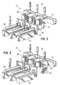
- Fig. 1 shows a multi-strand horizontal casting machine 10, and in particular a two-strand caster, with its associated downstream equipment.
- a three-strand casting machine is shown in more detail in Fig. 2 .
- Molten metal 12 travels from a common feed trough 14 to casting moulds 16 which form and produce cast ingots 18 of the desired cross section shape and size.
- the casting moulds 16 are generally made of metal (e. g. aluminum) body with a refractory entry tube, and may include graphite liners.
- Each mould 16 most commonly comprises a cooling jacket within the mould body connected to a first coolant source for cooling the molten metal passing through it to form a skin on the ingot.
- Cast ingots are then carried away by conveying devices 52 for downstream processing.
- Dedicated connecting troughs 20 connect each casting mould 16 to feed trough 14 to form each strand of the multi-strand casting machine 10.
- a shutoff gate 22 is positioned in each connecting trough 20 adjacent the feed trough 14. The shutoff gate 22 is open for normal operation and can be closed to isolate individual strands from the molten metal 12, in the case of a shut down.
- Each connecting. trough is provided with a drop-down portion 24 adjacent the casting mould 16. This drop-down portion 24 remains in an upright position for normal operation of the caster 10.
- Fig. 3 illustrates one shutoff gate 22 in its closed position to isolate the particular strand from the feed trough 14.
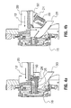
- Figs. 4a and 4b are cross-sectional views showing respectively the operational and shutdown positions of the drop-down portion 24.
- Each drop-down portion 24 is preferably in the form of a block of refractory material with a passageway 25 therein to carry the molten metal.
- This passageway 25 has an inlet in the top face of the block and an outlet in an end face thereof, which align respectively with an outlet opening in the connecting trough 20 and an inlet opening to a mould 16.
- a Fiberfrax TM paper is applied to the contacting faces.
- the feed trough 14 and the connecting troughs 20 are preferably heated troughs. This helps to keep the metal in molten form as it travels to the casting mould.
- a feed trough 14 has been illustrated in Figs. 2 and 3 as being connected to the casting moulds 16 via dedicated connecting troughs 20, it is to be understood that the feed trough 14 can also be connected via a single header box (not shown) for supplying molten metal to each casting mould 16.
- the shutoff gate 22 lies adjacent the header box to isolate it from the feed trough during shutdown.
- each casting mould 16 preferably includes a two piece mould body 17 machined from aluminum which includes an annular channel 26 within the mould body.
- a refractory entry channel 19 can also be included with the mould 16, and that mates at its inlet end with a downstream end of the drop-down trough section 24.
- the mould is further lined with a graphite member 21.
- the channel 26 is connected to a second coolant supply line 28 and includes at least one annular slot or a plurality of holes 32 running from the channel 26 to a surface of the casting mould 16 adjacent the emerging ingot 18. Coolant from the second coolant supply line 28 flows out through the slot or holes 32 to impinge against the skin formed on the emerging ingot 18, thereby cooling and solidifying the ingot 18.
- a gas supply line 30 is also connected to the channel 26 to supply gas for clearing the slot or holes 32 of coolant and preventing the entry of molten metal 12.
- Another embodiment of mould suitable for use is described in US Patent No. 7,079,186 .
- the flowchart of Fig. 6 illustrates some possible reasons for shutting down a particular strand of a multi-strand casting machine 10, and the subsequent steps that can be taken to isolate and shut down the strand.
- the breakout detector may be any sensor capable of identifying a liquid metal leak from the mould, but is preferably one as described in US Patent 6,446, 704 (Collins ).
- Other faults that may cause the sequence of events in the flowchart to occur include failure of a cutoff saw used to cut the continuously emerging ingot into sections or loss of synchronization between the ingot withdrawal mechanism and the ingot movement.
- the apparatus that may give rise to these types of shutdown events is described in US Patent No. 7,028,750 .
- the particular strand is isolated from the feed trough 14 or from the reservoir, depending on the configuration, by closing the shutoff gate 22.
- the shutoff gate 22 is preferably biased closed and includes an actuator for holding the gate in an open position for normal operation. Suitable shutoff gates can include, for example normally closed gate valves.
- the next step is to lower the drop-down portion 24 to a downwards position so as to rapidly drain any molten metal 12 from the connecting trough 20 and the casting mould 16. The molten metal 12 can then be collected via channels 33 into dump bins 34, such as those illustrated in Fig. 1 .
- a further preferred step is to stop coolant flow from the coolant supply line 28 to the ingot 18.
- a final preferred step is to inject gas from the gas supply line 30 to the annular channel 26 and through the outlet holes 32 to clear these holes 32 of coolant and molten metal.
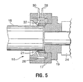
- Figs. 7 and 8 show a starter block 36 for starting up or restarting a particular strand.
- the block 36 is generally elongated and sized at one end to be inserted in the mouth of the mould 16 and supported on the conveying device 52.
- a threaded, conical, recess 38 is formed in the block 36, parallel to the direction of flow of molten metal, for receiving molten metal.
- the starter block further comprises a circumferential groove 48 for receiving an O-ring 40.
- the O-ring 40 is adapted to engage the mouth of the casting mould 16 to positively seal the block 36 against the casting mould 16.
- the starter block 36 has a concave annular depression 42 adjacent the mould 16 adapted to deflect coolant away from the O-ring 40 thereby preventing contact between the coolant and the molten metal.
- the starter block 36 further or alternatively comprises an air vent 44, formed between the threaded recess 38 and a surface of the starter block 36, to allow venting of air from the recess 38 as it receives molten metal 12.
- a porous plug 46 is provided in the recess 38 at the entrance to the air vent 44 that allows venting of air from the recess 38 while preventing molten metal from passing through the vent 44.
- the starter block 36 disengages from the mouth of the mould 16 and exposes the ingot to the impinging coolant streams, thereby cooling and further solidifying the ingot 18.
- the starter block can then be unthreaded from the ingot for re-use.
Landscapes
- Engineering & Computer Science (AREA)
- Mechanical Engineering (AREA)
- Continuous Casting (AREA)
- Molds, Cores, And Manufacturing Methods Thereof (AREA)
- Control And Safety Of Cranes (AREA)
- Injection Moulding Of Plastics Or The Like (AREA)
Claims (2)
- Vorrichtung (10) zum kontinuierlichen Gießen von Metall-Gussblöcken (18), mit:(a) einer Rinne (14, 20) zum Führen geschmolzenen Metalls;(b) einer Gussform (16) zum Aufnehmen geschmolzenen Metalls und zum Gießen des Metalls in Metall-Gussblöcke;(c) einer Kühlmittelquelle, die angeordnet ist, um die Oberfläche des Gussblocks zu beaufschlagen und den Gussblock zu kühlen;(d) einer Fördereinrichtung (52) zum Abtransportieren des gegossenen Gussblocks aus der Gussform, ausgerichtet in Gussrichtung des Gussblocks;(e) einem gestreckten Starterblock (36), der ausgeführt ist, um in die Form eingebracht zu sein und durch die Fördereinrichtung gehalten ist; und(f) einem O-Ring (40), der an dem Starterblock befestigt ist, um den Blocks gegen die Gussform abzudichten;gekennzeichnet dadurch, dass:der gestreckte Starterblock eine darin vorgesehene, mit einem Gewinde versehene Ausnehmung (38) zum Aufnehmen geschmolzenen Metalls, aufweist;wobei der Starterblock ferner eine Entlüftung (44) aufweist, die in der mit dem Gewinde versehenen Ausnehmung ausgebildet ist und zu einer an den Starterblock angrenzende Fläche führt, um die Entlüftung von Luft aus der Ausnehmung, wenn diese geschmolzenes Metall aufnimmt, zu gestatten; und/oderwobei der Starterblock an einer äußeren Fläche desselben eine konkave kreisringförmige Vertiefung, angrenzend an die Form aufweist, die ausgeführt ist, um Kühlmittel weg von dem O-Ring zu lenken.
- Vorrichtung gemäß Anspruch 1, weiter mit einem porösen Verschluss (46), der in der mit dem Gewinde versehenen Ausnehmung, angrenzend an die Entlüftung platziert ist, um geschmolzenes Metall in der Ausnehmung zu halten, während die Entlüftung von Luft aus der Ausnehmung gestattet ist.
Applications Claiming Priority (2)
| Application Number | Priority Date | Filing Date | Title |
|---|---|---|---|
| US10/735,074 US7004229B2 (en) | 2003-12-11 | 2003-12-11 | Method and apparatus for starting and stopping a horizontal casting machine |
| EP04802273A EP1691943B1 (de) | 2003-12-11 | 2004-12-09 | Verfahren und vorrichtung zum starten und anhalten einer horizontalgiessmaschine |
Related Parent Applications (2)
| Application Number | Title | Priority Date | Filing Date |
|---|---|---|---|
| EP04802273A Division EP1691943B1 (de) | 2003-12-11 | 2004-12-09 | Verfahren und vorrichtung zum starten und anhalten einer horizontalgiessmaschine |
| EP04802273.5 Division | 2004-12-09 |
Publications (2)
| Publication Number | Publication Date |
|---|---|
| EP2058064A1 EP2058064A1 (de) | 2009-05-13 |
| EP2058064B1 true EP2058064B1 (de) | 2013-06-26 |
Family
ID=34653526
Family Applications (2)
| Application Number | Title | Priority Date | Filing Date |
|---|---|---|---|
| EP09153186.3A Expired - Lifetime EP2058064B1 (de) | 2003-12-11 | 2004-12-09 | Vorrichtung zum kontinuierlichen Gießen von Metallblöcken |
| EP04802273A Expired - Lifetime EP1691943B1 (de) | 2003-12-11 | 2004-12-09 | Verfahren und vorrichtung zum starten und anhalten einer horizontalgiessmaschine |
Family Applications After (1)
| Application Number | Title | Priority Date | Filing Date |
|---|---|---|---|
| EP04802273A Expired - Lifetime EP1691943B1 (de) | 2003-12-11 | 2004-12-09 | Verfahren und vorrichtung zum starten und anhalten einer horizontalgiessmaschine |
Country Status (12)
| Country | Link |
|---|---|
| US (1) | US7004229B2 (de) |
| EP (2) | EP2058064B1 (de) |
| JP (2) | JP4559434B2 (de) |
| KR (1) | KR101177584B1 (de) |
| CN (2) | CN1894058B (de) |
| AT (1) | ATE469713T1 (de) |
| CA (1) | CA2546061C (de) |
| DE (1) | DE602004027527D1 (de) |
| ES (2) | ES2433923T3 (de) |
| NO (2) | NO337973B1 (de) |
| PT (2) | PT2058064E (de) |
| WO (1) | WO2005056216A1 (de) |
Families Citing this family (8)
| Publication number | Priority date | Publication date | Assignee | Title |
|---|---|---|---|---|
| US7926548B2 (en) * | 2004-11-16 | 2011-04-19 | Rti International Metals, Inc. | Method and apparatus for sealing an ingot at initial startup |
| JP5004195B2 (ja) * | 2009-05-14 | 2012-08-22 | 株式会社日本製鋼所 | コールドクルーシブル溶解法 |
| CA2817810C (en) | 2010-12-22 | 2015-02-10 | Novelis Inc. | Elimination of shrinkage cavity in cast ingots |
| WO2016178877A1 (en) * | 2015-05-04 | 2016-11-10 | Retech Systems Llc | Tapered threaded puller head |
| NO341337B1 (en) * | 2015-07-03 | 2017-10-16 | Norsk Hydro As | Equipment for continuous or semi-continuous casting of metal with improved metal filling arrangement |
| CN117680631B (zh) * | 2023-11-08 | 2024-10-25 | 广东伟业铝材有限公司 | 一种铝合金圆棒铸造设备 |
| KR102844558B1 (ko) | 2024-04-16 | 2025-08-11 | 주식회사 지엠알 | 수평형 알루미늄 괴 제조설비 |
| CN118123000A (zh) * | 2024-05-06 | 2024-06-04 | 沈阳富创精密设备股份有限公司 | 一种适用于异形浇铸槽的多位置浇铸装置 |
Family Cites Families (35)
| Publication number | Priority date | Publication date | Assignee | Title |
|---|---|---|---|---|
| US2880989A (en) * | 1956-11-13 | 1959-04-07 | Kaiser Aluminium Chem Corp | Apparatus for discharging molten metal |
| US3344845A (en) * | 1965-08-16 | 1967-10-03 | Aluminum Co Of America | Horizontal continuous casting apparatus |
| US3455369A (en) * | 1966-09-16 | 1969-07-15 | Aluminum Co Of America | Horizontal continuous casting |
| US3653427A (en) * | 1969-08-12 | 1972-04-04 | Mitsubishi Heavy Ind Ltd | Dummy bar mechanism |
| US3630266A (en) * | 1969-11-21 | 1971-12-28 | Technicon Corp | Continuous casting process |
| US3623534A (en) * | 1970-08-19 | 1971-11-30 | American Pipe & Constr Co | A method for starting a continuous casting |
| US3908746A (en) * | 1973-03-30 | 1975-09-30 | Clark Automation Inc | Continuous casting machine |
| US3850225A (en) * | 1973-09-27 | 1974-11-26 | Gen Motors Corp | Start-up method and apparatus for continuous casting |
| GB1505063A (en) * | 1977-01-24 | 1978-03-22 | Nauch Proizv Obiedine | Gas venting in the mould of a continuous casting machine |
| AT348170B (de) * | 1977-03-25 | 1979-02-12 | Voest Ag | Anfahrstrang fuer stranggiessanlagen |
| CH631645A5 (de) * | 1978-08-24 | 1982-08-31 | Alusuisse | Vorrichtung zum herausziehen eines metallstranges aus der kokille einer stranggussanlage. |
| IT1104455B (it) * | 1978-09-05 | 1985-10-21 | Piombino Acciaierie | Materozza per lingottiera di colata continua |
| GB2037634B (en) * | 1978-11-27 | 1983-02-09 | Secretary Industry Brit | Casting thixotropic material |
| JPS602145B2 (ja) * | 1979-07-09 | 1985-01-19 | 日本鋼管株式会社 | 水平連続鋳造用タンデイツシユ |
| US4381030A (en) * | 1980-01-25 | 1983-04-26 | Concast Ag | Dummy bar head for a steel continuous casting installation containing an open-ended mold |
| US4291748A (en) * | 1980-02-25 | 1981-09-29 | Concast Incorporated | Dummy bar for a continuous casting machine |
| US4454907A (en) * | 1981-12-02 | 1984-06-19 | Aluminum Company Of America | Continuous casting mold-starting plug alignment system |
| DE3411769C2 (de) * | 1984-03-30 | 1986-03-20 | Mannesmann Ag, 4000 Duesseldorf | Horizontalstranggießvorrichtung |
| NZ209807A (en) * | 1984-07-27 | 1986-11-12 | Showa Aluminium Ind | Horizontal continuous casting of metal |
| JPS6289552A (ja) * | 1985-10-15 | 1987-04-24 | Nippon Kokan Kk <Nkk> | 水平連続鋳造機 |
| DE3611287C1 (de) * | 1986-04-04 | 1987-04-23 | Mannesmann Ag | Horizontalstranggiessvorrichtung fuer mehrere Giessstraenge |
| JPH0832356B2 (ja) * | 1987-07-07 | 1996-03-29 | 昭和電工株式会社 | 金属の水平連続鋳造方法及び装置 |
| JPH02169158A (ja) * | 1988-12-21 | 1990-06-29 | Sumitomo Metal Ind Ltd | タンディッシュ及びそれを用いた連続鋳造方法 |
| JPH0744354Y2 (ja) * | 1989-03-17 | 1995-10-11 | ワイケイケイ株式会社 | 水平連続鋳造装置における樋遮断装置 |
| JPH0675749B2 (ja) * | 1989-05-11 | 1994-09-28 | 吉田工業株式会社 | 水平連続鋳造装置 |
| JPH0620599B2 (ja) * | 1989-05-11 | 1994-03-23 | 吉田工業株式会社 | 水平連続鋳造における鋳出し方法 |
| US5228496A (en) * | 1989-05-11 | 1993-07-20 | Yoshida Kogyo K.K. | Cast starting method in horizontal continuous casting |
| US6446704B1 (en) * | 1997-06-27 | 2002-09-10 | Richard J. Collins | Continuous casting mold plug activation and bleedout detection system |
| FR2779673B1 (fr) * | 1998-06-10 | 2000-08-18 | Meca Lebeau | Mannequin d'une installation de coulee continue en lingotiere |
| NL1014024C2 (nl) | 2000-01-06 | 2001-07-09 | Corus Technology Bv | Inrichting en werkwijze voor het continu of semi-continu gieten van aluminium. |
| US7079186B2 (en) | 2000-10-13 | 2006-07-18 | Pentax Corporation | Diaphragm device of a television camera lens for a CCTV surveillance camera |
| CA2350861C (en) | 2001-06-15 | 2008-09-16 | London Machinery Inc. | Flip chute safety and assist mechanism |
| US6609603B2 (en) * | 2001-06-18 | 2003-08-26 | London Machinery Inc. | Flip chute safety and assist mechanism |
| CN1208154C (zh) * | 2002-08-20 | 2005-06-29 | 西安理工大学 | 水平连铸方法生产铸铁管的装置 |
| US7028750B2 (en) | 2003-12-11 | 2006-04-18 | Novelis, Inc. | Apparatus and method for horizontal casting and cutting of metal billets |
-
2003
- 2003-12-11 US US10/735,074 patent/US7004229B2/en not_active Expired - Lifetime
-
2004
- 2004-12-09 ES ES09153186T patent/ES2433923T3/es not_active Expired - Lifetime
- 2004-12-09 PT PT91531863T patent/PT2058064E/pt unknown
- 2004-12-09 DE DE602004027527T patent/DE602004027527D1/de not_active Expired - Lifetime
- 2004-12-09 PT PT04802273T patent/PT1691943E/pt unknown
- 2004-12-09 EP EP09153186.3A patent/EP2058064B1/de not_active Expired - Lifetime
- 2004-12-09 AT AT04802273T patent/ATE469713T1/de active
- 2004-12-09 CN CN2004800370501A patent/CN1894058B/zh not_active Expired - Lifetime
- 2004-12-09 JP JP2006543329A patent/JP4559434B2/ja not_active Expired - Lifetime
- 2004-12-09 ES ES04802273T patent/ES2346225T3/es not_active Expired - Lifetime
- 2004-12-09 CA CA002546061A patent/CA2546061C/en not_active Expired - Lifetime
- 2004-12-09 WO PCT/CA2004/002096 patent/WO2005056216A1/en not_active Ceased
- 2004-12-09 KR KR1020067013831A patent/KR101177584B1/ko not_active Expired - Lifetime
- 2004-12-09 CN CN2009101704330A patent/CN101653821B/zh not_active Expired - Lifetime
- 2004-12-09 EP EP04802273A patent/EP1691943B1/de not_active Expired - Lifetime
-
2006
- 2006-07-07 NO NO20063152A patent/NO337973B1/no unknown
-
2010
- 2010-05-28 JP JP2010122262A patent/JP5230687B2/ja not_active Expired - Lifetime
-
2015
- 2015-07-15 NO NO20150938A patent/NO339942B1/no unknown
Also Published As
| Publication number | Publication date |
|---|---|
| CN101653821B (zh) | 2012-06-06 |
| US7004229B2 (en) | 2006-02-28 |
| CA2546061C (en) | 2009-05-12 |
| US20050126744A1 (en) | 2005-06-16 |
| PT2058064E (pt) | 2013-09-03 |
| KR101177584B1 (ko) | 2012-08-27 |
| KR20060121929A (ko) | 2006-11-29 |
| CA2546061A1 (en) | 2005-06-23 |
| NO337973B1 (no) | 2016-07-18 |
| EP1691943A1 (de) | 2006-08-23 |
| NO339942B1 (no) | 2017-02-20 |
| JP2007513772A (ja) | 2007-05-31 |
| CN1894058A (zh) | 2007-01-10 |
| EP1691943B1 (de) | 2010-06-02 |
| NO20150938A1 (no) | 2006-07-07 |
| JP5230687B2 (ja) | 2013-07-10 |
| EP1691943A4 (de) | 2007-03-14 |
| ES2433923T3 (es) | 2013-12-13 |
| JP4559434B2 (ja) | 2010-10-06 |
| ES2346225T3 (es) | 2010-10-13 |
| PT1691943E (pt) | 2010-06-28 |
| JP2010179372A (ja) | 2010-08-19 |
| WO2005056216A1 (en) | 2005-06-23 |
| CN101653821A (zh) | 2010-02-24 |
| ATE469713T1 (de) | 2010-06-15 |
| EP2058064A1 (de) | 2009-05-13 |
| NO20063152L (no) | 2006-07-07 |
| CN1894058B (zh) | 2010-05-26 |
| DE602004027527D1 (de) | 2010-07-15 |
Similar Documents
| Publication | Publication Date | Title |
|---|---|---|
| JP5230687B2 (ja) | 水平鋳造機の始動及び停止方法及び装置 | |
| KR100754567B1 (ko) | 스트립 연속 주조 장치 및 그 사용방법 | |
| US8365807B2 (en) | Reduction of butt curl by pulsed water flow in DC casting | |
| CN101557892B (zh) | 用于带有可渗透周壁的熔融金属模具的气流控制系统 | |
| HU194757B (en) | Release valve for casting ladles containing melt and casting ladle having the release valve | |
| US6929052B2 (en) | Method and apparatus for uphill casting with a slide valve closure placed on the casting table | |
| KR100426672B1 (ko) | 직립로의주조장에서액상금속을이송하는장치및이장치의작동방법 | |
| EP1637254B1 (de) | Formmontage | |
| EP1640088B1 (de) | Druckgiessen von Batterieklemmen | |
| KR101224014B1 (ko) | 턴디쉬의 주입노즐 급속 폐쇄 장치 및 방법 | |
| US4308908A (en) | Methods and apparatus for effecting quick mandrel changes in continuous casting operations | |
| CA2168120A1 (en) | Method and device for unplugging a molten metal discharge port | |
| EP1329271A1 (de) | Vorrichtung zum Erleichtern des Öffnens eines Gefässes für schmelzflüssige Metalle | |
| KR200184910Y1 (ko) | 연속주조기용 슬래그 유입방지장치 | |
| KR100840238B1 (ko) | 용강 유출 차단장치 | |
| WO1995004622A1 (en) | Method and device for unplugging a molten metal discharge port | |
| KR20030035663A (ko) | 연속주조설비의 세그먼트 갭 개방장치 |
Legal Events
| Date | Code | Title | Description |
|---|---|---|---|
| PUAI | Public reference made under article 153(3) epc to a published international application that has entered the european phase |
Free format text: ORIGINAL CODE: 0009012 |
|
| AC | Divisional application: reference to earlier application |
Ref document number: 1691943 Country of ref document: EP Kind code of ref document: P |
|
| AK | Designated contracting states |
Kind code of ref document: A1 Designated state(s): AT BE BG CH CY CZ DE DK EE ES FI FR GB GR HU IE IS IT LI LT LU MC NL PL PT RO SE SI SK TR |
|
| AX | Request for extension of the european patent |
Extension state: AL BA HR LV MK YU |
|
| 17P | Request for examination filed |
Effective date: 20091111 |
|
| AKX | Designation fees paid |
Designated state(s): AT BE BG CH CY CZ DE DK EE ES FI FR GB GR HU IE IS IT LI LT LU MC NL PL PT RO SE SI SK TR |
|
| AXX | Extension fees paid |
Extension state: YU Payment date: 20091111 Extension state: MK Payment date: 20091111 Extension state: LV Payment date: 20091111 Extension state: HR Payment date: 20091111 Extension state: BA Payment date: 20091111 Extension state: AL Payment date: 20091111 |
|
| 17Q | First examination report despatched |
Effective date: 20100629 |
|
| GRAP | Despatch of communication of intention to grant a patent |
Free format text: ORIGINAL CODE: EPIDOSNIGR1 |
|
| GRAS | Grant fee paid |
Free format text: ORIGINAL CODE: EPIDOSNIGR3 |
|
| RAP1 | Party data changed (applicant data changed or rights of an application transferred) |
Owner name: NOVELIS INC. |
|
| GRAA | (expected) grant |
Free format text: ORIGINAL CODE: 0009210 |
|
| AC | Divisional application: reference to earlier application |
Ref document number: 1691943 Country of ref document: EP Kind code of ref document: P |
|
| AK | Designated contracting states |
Kind code of ref document: B1 Designated state(s): AT BE BG CH CY CZ DE DK EE ES FI FR GB GR HU IE IS IT LI LT LU MC NL PL PT RO SE SI SK TR |
|
| AX | Request for extension of the european patent |
Extension state: AL BA HR LV MK YU |
|
| REG | Reference to a national code |
Ref country code: GB Ref legal event code: FG4D |
|
| REG | Reference to a national code |
Ref country code: CH Ref legal event code: EP |
|
| REG | Reference to a national code |
Ref country code: AT Ref legal event code: REF Ref document number: 618463 Country of ref document: AT Kind code of ref document: T Effective date: 20130715 |
|
| REG | Reference to a national code |
Ref country code: IE Ref legal event code: FG4D |
|
| REG | Reference to a national code |
Ref country code: CH Ref legal event code: NV Representative=s name: E. BLUM AND CO. AG PATENT- UND MARKENANWAELTE , CH |
|
| REG | Reference to a national code |
Ref country code: DE Ref legal event code: R096 Ref document number: 602004042569 Country of ref document: DE Effective date: 20130822 |
|
| REG | Reference to a national code |
Ref country code: PT Ref legal event code: SC4A Free format text: AVAILABILITY OF NATIONAL TRANSLATION Effective date: 20130828 |
|
| REG | Reference to a national code |
Ref country code: NL Ref legal event code: T3 |
|
| PG25 | Lapsed in a contracting state [announced via postgrant information from national office to epo] |
Ref country code: SE Free format text: LAPSE BECAUSE OF FAILURE TO SUBMIT A TRANSLATION OF THE DESCRIPTION OR TO PAY THE FEE WITHIN THE PRESCRIBED TIME-LIMIT Effective date: 20130626 Ref country code: GR Free format text: LAPSE BECAUSE OF FAILURE TO SUBMIT A TRANSLATION OF THE DESCRIPTION OR TO PAY THE FEE WITHIN THE PRESCRIBED TIME-LIMIT Effective date: 20130927 Ref country code: FI Free format text: LAPSE BECAUSE OF FAILURE TO SUBMIT A TRANSLATION OF THE DESCRIPTION OR TO PAY THE FEE WITHIN THE PRESCRIBED TIME-LIMIT Effective date: 20130626 Ref country code: LT Free format text: LAPSE BECAUSE OF FAILURE TO SUBMIT A TRANSLATION OF THE DESCRIPTION OR TO PAY THE FEE WITHIN THE PRESCRIBED TIME-LIMIT Effective date: 20130626 Ref country code: SI Free format text: LAPSE BECAUSE OF FAILURE TO SUBMIT A TRANSLATION OF THE DESCRIPTION OR TO PAY THE FEE WITHIN THE PRESCRIBED TIME-LIMIT Effective date: 20130626 |
|
| REG | Reference to a national code |
Ref country code: LT Ref legal event code: MG4D |
|
| PG25 | Lapsed in a contracting state [announced via postgrant information from national office to epo] |
Ref country code: BG Free format text: LAPSE BECAUSE OF FAILURE TO SUBMIT A TRANSLATION OF THE DESCRIPTION OR TO PAY THE FEE WITHIN THE PRESCRIBED TIME-LIMIT Effective date: 20130926 |
|
| REG | Reference to a national code |
Ref country code: ES Ref legal event code: FG2A Ref document number: 2433923 Country of ref document: ES Kind code of ref document: T3 Effective date: 20131213 |
|
| PG25 | Lapsed in a contracting state [announced via postgrant information from national office to epo] |
Ref country code: IS Free format text: LAPSE BECAUSE OF FAILURE TO SUBMIT A TRANSLATION OF THE DESCRIPTION OR TO PAY THE FEE WITHIN THE PRESCRIBED TIME-LIMIT Effective date: 20131026 Ref country code: CY Free format text: LAPSE BECAUSE OF FAILURE TO SUBMIT A TRANSLATION OF THE DESCRIPTION OR TO PAY THE FEE WITHIN THE PRESCRIBED TIME-LIMIT Effective date: 20130731 Ref country code: EE Free format text: LAPSE BECAUSE OF FAILURE TO SUBMIT A TRANSLATION OF THE DESCRIPTION OR TO PAY THE FEE WITHIN THE PRESCRIBED TIME-LIMIT Effective date: 20130626 Ref country code: CZ Free format text: LAPSE BECAUSE OF FAILURE TO SUBMIT A TRANSLATION OF THE DESCRIPTION OR TO PAY THE FEE WITHIN THE PRESCRIBED TIME-LIMIT Effective date: 20130626 Ref country code: BE Free format text: LAPSE BECAUSE OF FAILURE TO SUBMIT A TRANSLATION OF THE DESCRIPTION OR TO PAY THE FEE WITHIN THE PRESCRIBED TIME-LIMIT Effective date: 20130626 Ref country code: SK Free format text: LAPSE BECAUSE OF FAILURE TO SUBMIT A TRANSLATION OF THE DESCRIPTION OR TO PAY THE FEE WITHIN THE PRESCRIBED TIME-LIMIT Effective date: 20130626 |
|
| PG25 | Lapsed in a contracting state [announced via postgrant information from national office to epo] |
Ref country code: RO Free format text: LAPSE BECAUSE OF FAILURE TO SUBMIT A TRANSLATION OF THE DESCRIPTION OR TO PAY THE FEE WITHIN THE PRESCRIBED TIME-LIMIT Effective date: 20130626 Ref country code: PL Free format text: LAPSE BECAUSE OF FAILURE TO SUBMIT A TRANSLATION OF THE DESCRIPTION OR TO PAY THE FEE WITHIN THE PRESCRIBED TIME-LIMIT Effective date: 20130626 |
|
| PG25 | Lapsed in a contracting state [announced via postgrant information from national office to epo] |
Ref country code: CY Free format text: LAPSE BECAUSE OF FAILURE TO SUBMIT A TRANSLATION OF THE DESCRIPTION OR TO PAY THE FEE WITHIN THE PRESCRIBED TIME-LIMIT Effective date: 20130626 |
|
| PG25 | Lapsed in a contracting state [announced via postgrant information from national office to epo] |
Ref country code: DK Free format text: LAPSE BECAUSE OF FAILURE TO SUBMIT A TRANSLATION OF THE DESCRIPTION OR TO PAY THE FEE WITHIN THE PRESCRIBED TIME-LIMIT Effective date: 20130626 |
|
| PLBE | No opposition filed within time limit |
Free format text: ORIGINAL CODE: 0009261 |
|
| STAA | Information on the status of an ep patent application or granted ep patent |
Free format text: STATUS: NO OPPOSITION FILED WITHIN TIME LIMIT |
|
| 26N | No opposition filed |
Effective date: 20140327 |
|
| REG | Reference to a national code |
Ref country code: DE Ref legal event code: R097 Ref document number: 602004042569 Country of ref document: DE Effective date: 20140327 |
|
| PG25 | Lapsed in a contracting state [announced via postgrant information from national office to epo] |
Ref country code: MC Free format text: LAPSE BECAUSE OF FAILURE TO SUBMIT A TRANSLATION OF THE DESCRIPTION OR TO PAY THE FEE WITHIN THE PRESCRIBED TIME-LIMIT Effective date: 20130626 Ref country code: LU Free format text: LAPSE BECAUSE OF FAILURE TO SUBMIT A TRANSLATION OF THE DESCRIPTION OR TO PAY THE FEE WITHIN THE PRESCRIBED TIME-LIMIT Effective date: 20131209 |
|
| REG | Reference to a national code |
Ref country code: IE Ref legal event code: MM4A |
|
| PG25 | Lapsed in a contracting state [announced via postgrant information from national office to epo] |
Ref country code: IE Free format text: LAPSE BECAUSE OF NON-PAYMENT OF DUE FEES Effective date: 20131209 |
|
| PG25 | Lapsed in a contracting state [announced via postgrant information from national office to epo] |
Ref country code: TR Free format text: LAPSE BECAUSE OF FAILURE TO SUBMIT A TRANSLATION OF THE DESCRIPTION OR TO PAY THE FEE WITHIN THE PRESCRIBED TIME-LIMIT Effective date: 20130626 |
|
| PG25 | Lapsed in a contracting state [announced via postgrant information from national office to epo] |
Ref country code: HU Free format text: LAPSE BECAUSE OF FAILURE TO SUBMIT A TRANSLATION OF THE DESCRIPTION OR TO PAY THE FEE WITHIN THE PRESCRIBED TIME-LIMIT; INVALID AB INITIO Effective date: 20041209 |
|
| REG | Reference to a national code |
Ref country code: FR Ref legal event code: PLFP Year of fee payment: 12 |
|
| REG | Reference to a national code |
Ref country code: FR Ref legal event code: PLFP Year of fee payment: 13 |
|
| PG25 | Lapsed in a contracting state [announced via postgrant information from national office to epo] |
Ref country code: IT Free format text: LAPSE BECAUSE OF NON-PAYMENT OF DUE FEES Effective date: 20151209 |
|
| PG25 | Lapsed in a contracting state [announced via postgrant information from national office to epo] |
Ref country code: IT Free format text: LAPSE BECAUSE OF NON-PAYMENT OF DUE FEES Effective date: 20151209 |
|
| PGRI | Patent reinstated in contracting state [announced from national office to epo] |
Ref country code: IT Effective date: 20170710 |
|
| REG | Reference to a national code |
Ref country code: FR Ref legal event code: PLFP Year of fee payment: 14 |
|
| PGFP | Annual fee paid to national office [announced via postgrant information from national office to epo] |
Ref country code: NL Payment date: 20191125 Year of fee payment: 16 |
|
| REG | Reference to a national code |
Ref country code: NL Ref legal event code: MM Effective date: 20210101 |
|
| PG25 | Lapsed in a contracting state [announced via postgrant information from national office to epo] |
Ref country code: NL Free format text: LAPSE BECAUSE OF NON-PAYMENT OF DUE FEES Effective date: 20210101 |
|
| P01 | Opt-out of the competence of the unified patent court (upc) registered |
Effective date: 20230518 |
|
| PGFP | Annual fee paid to national office [announced via postgrant information from national office to epo] |
Ref country code: GB Payment date: 20231124 Year of fee payment: 20 |
|
| PGFP | Annual fee paid to national office [announced via postgrant information from national office to epo] |
Ref country code: PT Payment date: 20231122 Year of fee payment: 20 Ref country code: FR Payment date: 20231122 Year of fee payment: 20 Ref country code: DE Payment date: 20231121 Year of fee payment: 20 Ref country code: AT Payment date: 20231123 Year of fee payment: 20 |
|
| PGFP | Annual fee paid to national office [announced via postgrant information from national office to epo] |
Ref country code: ES Payment date: 20240102 Year of fee payment: 20 |
|
| PGFP | Annual fee paid to national office [announced via postgrant information from national office to epo] |
Ref country code: CH Payment date: 20240101 Year of fee payment: 20 |
|
| REG | Reference to a national code |
Ref country code: DE Ref legal event code: R071 Ref document number: 602004042569 Country of ref document: DE |
|
| REG | Reference to a national code |
Ref country code: CH Ref legal event code: PL |
|
| REG | Reference to a national code |
Ref country code: ES Ref legal event code: FD2A Effective date: 20241230 |
|
| REG | Reference to a national code |
Ref country code: GB Ref legal event code: PE20 Expiry date: 20241208 |
|
| REG | Reference to a national code |
Ref country code: AT Ref legal event code: MK07 Ref document number: 618463 Country of ref document: AT Kind code of ref document: T Effective date: 20241209 |
|
| PG25 | Lapsed in a contracting state [announced via postgrant information from national office to epo] |
Ref country code: PT Free format text: LAPSE BECAUSE OF EXPIRATION OF PROTECTION Effective date: 20241218 |
|
| PG25 | Lapsed in a contracting state [announced via postgrant information from national office to epo] |
Ref country code: GB Free format text: LAPSE BECAUSE OF EXPIRATION OF PROTECTION Effective date: 20241208 |
|
| PG25 | Lapsed in a contracting state [announced via postgrant information from national office to epo] |
Ref country code: ES Free format text: LAPSE BECAUSE OF EXPIRATION OF PROTECTION Effective date: 20241210 |
|
| PG25 | Lapsed in a contracting state [announced via postgrant information from national office to epo] |
Ref country code: PT Free format text: LAPSE BECAUSE OF EXPIRATION OF PROTECTION Effective date: 20241218 Ref country code: GB Free format text: LAPSE BECAUSE OF EXPIRATION OF PROTECTION Effective date: 20241208 Ref country code: ES Free format text: LAPSE BECAUSE OF EXPIRATION OF PROTECTION Effective date: 20241210 |
|
| PGFP | Annual fee paid to national office [announced via postgrant information from national office to epo] |
Ref country code: IT Payment date: 20231121 Year of fee payment: 20 |