EP2057295B1 - Rod or wire heat treatment system and related method - Google Patents
Rod or wire heat treatment system and related method Download PDFInfo
- Publication number
- EP2057295B1 EP2057295B1 EP07799599.1A EP07799599A EP2057295B1 EP 2057295 B1 EP2057295 B1 EP 2057295B1 EP 07799599 A EP07799599 A EP 07799599A EP 2057295 B1 EP2057295 B1 EP 2057295B1
- Authority
- EP
- European Patent Office
- Prior art keywords
- quenchant
- wire
- rod
- continuously provided
- heat transfer
- Prior art date
- Legal status (The legal status is an assumption and is not a legal conclusion. Google has not performed a legal analysis and makes no representation as to the accuracy of the status listed.)
- Not-in-force
Links
Images


Classifications
-
- C—CHEMISTRY; METALLURGY
- C21—METALLURGY OF IRON
- C21D—MODIFYING THE PHYSICAL STRUCTURE OF FERROUS METALS; GENERAL DEVICES FOR HEAT TREATMENT OF FERROUS OR NON-FERROUS METALS OR ALLOYS; MAKING METAL MALLEABLE, e.g. BY DECARBURISATION OR TEMPERING
- C21D1/00—General methods or devices for heat treatment, e.g. annealing, hardening, quenching or tempering
- C21D1/62—Quenching devices
- C21D1/63—Quenching devices for bath quenching
- C21D1/64—Quenching devices for bath quenching with circulating liquids
-
- C—CHEMISTRY; METALLURGY
- C21—METALLURGY OF IRON
- C21D—MODIFYING THE PHYSICAL STRUCTURE OF FERROUS METALS; GENERAL DEVICES FOR HEAT TREATMENT OF FERROUS OR NON-FERROUS METALS OR ALLOYS; MAKING METAL MALLEABLE, e.g. BY DECARBURISATION OR TEMPERING
- C21D1/00—General methods or devices for heat treatment, e.g. annealing, hardening, quenching or tempering
- C21D1/62—Quenching devices
- C21D1/63—Quenching devices for bath quenching
-
- C—CHEMISTRY; METALLURGY
- C21—METALLURGY OF IRON
- C21D—MODIFYING THE PHYSICAL STRUCTURE OF FERROUS METALS; GENERAL DEVICES FOR HEAT TREATMENT OF FERROUS OR NON-FERROUS METALS OR ALLOYS; MAKING METAL MALLEABLE, e.g. BY DECARBURISATION OR TEMPERING
- C21D8/00—Modifying the physical properties of ferrous metals or ferrous alloys by deformation combined with, or followed by, heat treatment
- C21D8/06—Modifying the physical properties of ferrous metals or ferrous alloys by deformation combined with, or followed by, heat treatment during manufacturing of rods or wires
-
- C—CHEMISTRY; METALLURGY
- C21—METALLURGY OF IRON
- C21D—MODIFYING THE PHYSICAL STRUCTURE OF FERROUS METALS; GENERAL DEVICES FOR HEAT TREATMENT OF FERROUS OR NON-FERROUS METALS OR ALLOYS; MAKING METAL MALLEABLE, e.g. BY DECARBURISATION OR TEMPERING
- C21D9/00—Heat treatment, e.g. annealing, hardening, quenching or tempering, adapted for particular articles; Furnaces therefor
- C21D9/52—Heat treatment, e.g. annealing, hardening, quenching or tempering, adapted for particular articles; Furnaces therefor for wires; for strips ; for rods of unlimited length
- C21D9/54—Furnaces for treating strips or wire
-
- C—CHEMISTRY; METALLURGY
- C21—METALLURGY OF IRON
- C21D—MODIFYING THE PHYSICAL STRUCTURE OF FERROUS METALS; GENERAL DEVICES FOR HEAT TREATMENT OF FERROUS OR NON-FERROUS METALS OR ALLOYS; MAKING METAL MALLEABLE, e.g. BY DECARBURISATION OR TEMPERING
- C21D9/00—Heat treatment, e.g. annealing, hardening, quenching or tempering, adapted for particular articles; Furnaces therefor
- C21D9/52—Heat treatment, e.g. annealing, hardening, quenching or tempering, adapted for particular articles; Furnaces therefor for wires; for strips ; for rods of unlimited length
- C21D9/54—Furnaces for treating strips or wire
- C21D9/56—Continuous furnaces for strip or wire
- C21D9/573—Continuous furnaces for strip or wire with cooling
- C21D9/5732—Continuous furnaces for strip or wire with cooling of wires; of rods
-
- C—CHEMISTRY; METALLURGY
- C21—METALLURGY OF IRON
- C21D—MODIFYING THE PHYSICAL STRUCTURE OF FERROUS METALS; GENERAL DEVICES FOR HEAT TREATMENT OF FERROUS OR NON-FERROUS METALS OR ALLOYS; MAKING METAL MALLEABLE, e.g. BY DECARBURISATION OR TEMPERING
- C21D1/00—General methods or devices for heat treatment, e.g. annealing, hardening, quenching or tempering
- C21D1/56—General methods or devices for heat treatment, e.g. annealing, hardening, quenching or tempering characterised by the quenching agents
- C21D1/60—Aqueous agents
Definitions
- the present invention relates to a rod or wire manufacturing system including at least one heating-cooling unit. Also, the present invention relates to a method for manufacturing a rod or wire including heating and subsequently cooling the rod or wire. Further, the present invention relates to the products resulting from the use of a rod or wire manufacturing system and/or a method for manufacturing a rod or wire including heating and subsequently cooling the rod or wire.
- Drawn rod or wires for industrial purposes can be made from a variety of metals or alloys including without limitation aluminum, copper, alloy steels, and carbon steels. When made using a carbon steel the carbon content can range from about 0.35 to 1.1 % by weight. Carbon steel may also contain alloying elements such as chromium (Cr), boron (B), silicon (Si) or combinations of these elements.
- alloying elements such as chromium (Cr), boron (B), silicon (Si) or combinations of these elements.
- a material is usually subjected to a heat treatment known as annealing.
- the heat treatment consists of passing a rod or wire through a heat source such as a furnace to heat the rod or wire to about 930°C to 1020°C.
- This high temperature treatment produces a uniform face centered cubic austenite phase with a regulated grain size to help determine the product's subsequent ductility.
- Subsequent cooling in air or more commonly in molten lead or fluidized sand produces a phase transformation from face centered cubic austenite to body centered cubic ferrite and orthorhombic cementite arranged in alternating plates, jointly called pearlite. This transformation is rapid since the sections treated are relatively small (generally less than 3.5 mm).
- the resulting structure consists of very fine pearlite preferably with no grain boundary ferrite or cementite.
- the fineness of the pearlite depends on the product chemistry and the temperature to which the product is reduced after austenitizing.
- fine pearlite rod or wire is able to be drawn to reductions of area up to and sometimes exceeding 97%, resulting in very high drawn filament strengths.
- the final drawn filament strength provides exceptional fatigue resistance due to the very fine pearlite size, superior surface quality and the alignment of cementite plates in the drawn direction.
- Heat processing metal objects by a fluidized bed is known where the temperature of a solid medium, such as sand suspended in a gas is used to regulate the rate of heat transfer.
- the rate of heat transferred to the surrounding media per unit surface area of the rod or wire is determined by the temperature of the media since the convective heat transfer coefficient is constant for the media chosen.
- Heat processing metal objects by means of a liquid lead bath or media is also known where the temperature of the liquid lead is used to regulate the rate of heat transfer.
- the rate of heat transferred to the surrounding media per unit surface area of the wire is determined by the temperature of the media.
- JP 57 110623 A method for heat treating wires is known in which the wires are guided after hot rolling through a cooling liquid in which bubbles are produced by blowing gas into the liquid.
- Heat processing metal objects by means of air is also known where the temperature and velocity of the air is used to regulate the rate of heat transfer.
- Metal alloys such as steel alloys are produced with many different characteristics for use in different industries for different purposes.
- a large demand has developed for steel strands or wires for use in industrial applications such as vehicle tires, bridge strands, prestressed strands, galvanized drawn wire, music wire, saw wire and other products to improve their durability and strength.
- tires are generally referred to as steel belted radials which are realized as stronger and last much longer than conventional, non-belted tires.
- Such a cooling unit includes at least one heat transfer coefficient adaptable quenching zone and at least one heat transfer coefficient adaptable soaking zone.
- the at least one heat transfer coefficient adaptable quenching zone is capable of quenching to a soaking temperature at least one continuously provided rod or at least one continuously provided wire.
- the at least one heat transfer coefficient adaptable soaking zone is capable of maintaining substantially at the soaking temperature the at least one continuously provided rod or the at least one continuously provided wire so as to be capable of substantially completing a heat treating.
- a heating-cooling operation includes at least one heating unit.
- Such heating unit is capable of heating to a preselected temperature at least one continuously provided rod or the at least one continuously provided wire.
- a heating-cooling operation also includes at least one feed unit and at least one take-up unit.
- the at least one feed unit is capable of continuously providing at least one rod or at least one wire.
- the at least one take-up unit is capable of continuously gathering the at least one heat treated rod or the at least one heat treated wire.
- One aspect of the present invention is to provide a cooling unit or a heating-cooling operation including a cooling unit both useable with a rod or wire manufacturing system.
- a cooling unit includes at least one heat transfer coefficient adaptable quenching zone and at least one heat transfer coefficient adaptable soaking zone.
- the at least one heat transfer coefficient adaptable quenching zone is capable of quenching to a soaking temperature at least one continuously provided rod or at least one continuously provided wire.
- the at least one heat transfer coefficient adaptable soaking zone is capable of maintaining substantially at the soaking temperature the at least one continuously provided rod or the at least one continuously provided wire so as to be capable of substantially completing a heat treating.
- a heating-cooling operation includes at least one heating unit.
- Such heating unit is capable of heating to a preselected temperature at least one continuously provided rod or the at least one continuously provided wire.
- a heating-cooling operation also includes at least one feed unit and at least one take-up unit.
- the at least one feed unit is capable of continuously providing at least one rod or at least one wire.
- the at least one take-up unit is capable of continuously gathering the at least one heat treated rod or the at least one heat treated wire.
- Another aspect of the present invention is to provide a rod or wire manufacturing system that includes at least one feed unit, at least one heating unit, at least one cooling unit, and at least one take-up unit.
- the at least one feed unit is capable of continuously providing at least one rod or at least one wire.
- the at least one heating unit is capable of heating to a preselected temperature the at least one continuously provided rod or the at least one continuously provided wire.
- the at least one cooling unit downstream of at least one heating unit includes at least one adaptable quenching zone and at least one adaptable soaking zone.
- the at least one adaptable quenching zone is capable of quenching to a preselected soak temperature the at least one continuously provided rod or the at least one continuously provided wire.
- the at least one adaptable soaking zone is capable of substantially maintaining at the preselected soak temperature the at least one continuously provided rod or the at least one continuously provided wire. In this manner, the at least one adaptable soaking zone facilitates a substantially complete heat treatment of the at least one continuously provided rod or the at least one continuously provided wire.
- the at least one take-up unit capable of continuously gathering the at least one heat treated rod or the at least one heat treated wire.
- Still another aspect of the present invention is to provide a method for manufacturing a rod or wire.
- Such method includes steps of providing, heating, quenching, substantially maintaining at a preselected temperature, and gathering at least one rod or at least one wire.
- the providing can be a continuous providing of at least one rod or at least one wire.
- the heating includes heating the at least one continuously provided rod or the at least one continuously provided wire to a preselected temperature.
- the quenching includes cooling the at least one continuously provided rod or the at least one continuously provided wire to a preselected soak temperature.
- the substantially maintaining at the preselected soak temperature can be achieved by providing at least a foaming liquid quenchant so as to substantially complete a heat treatment of the at least one continuously provided rod or the at least one continuously provided wire may be achievable.
- the gathering can be a continuous gathering of the at least one heat treated rod or the at least one heat treated wire.
- An additional aspect of the present invention is to provide a method for heat treating of a rod or wire.
- Such heat treating includes heating, quenching, and soaking.
- the heating includes a heating to a preselected temperature at least one continuously provided rod or at least one continuously provided wire.
- the quenching includes quenching to a soaking temperature the at least one continuously provided rod or the at least one continuously provided wire.
- the soaking includes providing at least a foaming liquid quenchant to substantially maintain at the soaking temperature the at least one continuously provided rod or the at least one continuously provided wire so as to be capable of substantially completing a heat treating.
- Another additional aspect of the present invention is to provide a method for treating metal.
- the method includes heating, subjecting to at least one quenchant, controlling, and removing.
- the heating includes heating the metal.
- the subjecting includes subjecting the heated metal to at least one quenchant comprising a liquid and a gas or gaseous media mixture.
- the controlling includes controlling the at least one liquid/gas or gaseous media mixture.
- the removing includes removing the treated metal from the quenchant.
- Still another additional aspect of the present invention is to provide a steel rod or steel wire comprising at least about 39 area percent fine pearlite.
- such a steel rod or steel wire includes up to about 45 area percent fine pearlite.
- An alternative aspect of the present invention is to provide a treated metal having an improved tensile strength.
- Such metal can be formed by heating, guiding to least one liquid and gas or gaseous media mixture, and removing.
- the heating includes heating a metal to a selected temperature.
- the guiding includes guiding the heated metal into at least one liquid and gas or gaseous media mixture to treat the metal.
- the removing includes removing the treated metal from the at least one liquid and or gaseous media mixture.
- a rod or wire manufacturing system 10 is shown constructed according to the present invention.
- a rod or wire manufacturing system 10 includes at least one feed unit 14, at least one heating-cooling operation 12, and at least one take-up unit 16.
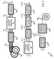
- a rod or wire manufacturing system 10 may include other components, such as, one or more drawing units 20, 20', & 20", one or more cleaning units 24 & 24", one or more coating units 26, and one or more finishing or combining units, such as one or more stranding units 30. Further, it will be appreciated that a rod or wire manufacturing system 10 might include some of the components depicted in FIG. 2 , all of the components depicted in FIG. 2 , components in addition to those depicted in FIG. 2 , or any combination thereof. As would be appreciated, FIGs. 1A , 1B , 1C , and 2 does not fully demonstrate all the mechanical, electrical and/or other components as used herein.
- one or more drawing units 20, 20', & 20", one or more cleaning units 24 & 24", one or more coating units 26, and one or more finishing or combining units, such as one or more stranding units 30 can be conventional in the trade and can vary in size, shape and efficiency depending on their particular requirements.
- a rod or wire manufacturing system 10 as depicted in FIG. 2 in operation using feed unit 14 provides one or more rods or wires 11 while a take-up unit 16 gathers one or more intermediate or finished products 18 that, in an aspect of an embodiment of the present invention, may be one or more heat treated rods or wires 11.
- the one or more rods or wires 11 can be run, for example, through a first drawing unit 20 to provide an intermediate product 17.
- Such intermediate product 17 can be subjected to a first heating-cooling operation 12 so as to anneal and quench the intermediate product 1.7 in turn resulting in an other intermediate product 17'.
- This other intermediate product 17' can then be run through a second drawing operation 20' to provide intermediate product 17".
- each unit performing one or more operations can result in one or more intermediate products 17, 17', 17", ... 17 (n) , 17 (n-1) .
- a take-up unit 16 gathers one or more intermediate or finished products 18 that might be used individually as a feedstock in a further manufacturing process or, alternatively, brought together or combined in one or more operations, such as by using a stranding unit 30 as depicted in FIG. 2 , to create an intermediate or finished product 18 to be used in a brought together or combined form as a feedstock in a further manufacturing process.
- intermediate or finished product 18 can include, be used as, or be included in, without limitation, any one of wire (e.g., fencing wire; livestock wire including without limitation wire for cattle fencing, sheep fencing, horse fencing, rabbit proof fencing, ...
- horticultural wire including without limitation trellising; aquaculture wire including without limitation marine mesh cages; bright wire; galvanized wire; chainmesh wire; mechanical spring wire; nail wire; concrete reinforcing wire ... etc.); rod and/or bar (e.g., coiled rod, straight rod, rounds, squares, hexagons, deformed bar, flats, light structural ... etc.); reinforcing (e.g., mesh bar, reinforcing bar, mining mesh, industrial mesh, rural mesh ... etc.); steel in concrete (e.g., roads, bridges, tunnels, houses, residential buildings, warehouses, shopping centers, factories, accessories, concrete pipes, railway sleepers...
- concrete e.g., roads, bridges, tunnels, houses, residential buildings, warehouses, shopping centers, factories, accessories, concrete pipes, railway sleepers...
- mining e.g., dragline ropes, shovel ropes, strata control bolts, strata control mesh, cable belt, ... etc.
- manufacturing e.g., spring manufacturing including without limitation rail clips, general springs, mattress coils and/or springs, ... etc., welding including without limitation welding electrodes and/or welding wire, fabrication including without limitation screens, grating, and sheds; fasteners including without limitation nails and other fasteners, automotive including without limitation springs, tire cord, tire bead wire, other steel tire reinforcement, bright bar ... etc.; ... etc.).
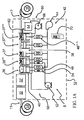
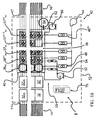
- FIGs. 1A and 1B depicted a heating-cooling operation 12, in plan view and top view respectfully, according to an aspect of the present invention.
- a feed unit 14 that provides one or more rods or wires 11 to one or more heating units 32, 32' to heat the one or more rods or wires 11 to a preselected temperature.
- a cooling unit 8 that includes one or more adaptable quenching zones 36, ..., 36( n-1 ) and one or more adaptable soaking zones 37, ..., 37 (n-1) , 37 (n) ,
- FIGs. 1A , 1B , and 1C depict second cell type 90 within a quenchant reservoir 40, according to an aspect of an embodiment of the present invention, for use as one or more adaptable quenching zones 36, 36 (n-1) .
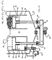
- FIG. 1C depicts further details about a second cell type 90.
- second cell type 90 can be capable of providing a quenchant, for example, as a liquid welling up above the upper level of the second cell type 90.
- a flow of the liquid quenchant 38 can be controlled by a second heat transfer adjuster 50 that includes a liquid quenchant supplier 52, such as a pump, and an adjusting mechanism 54, such as a valve, a flow meter, or valve in combination with a flow meter.
- a liquid quenchant supplier 52 such as a pump
- an adjusting mechanism 54 such as a valve, a flow meter, or valve in combination with a flow meter.
- a flow rate of liquid quenchant 38 to a second cell type 90 of adaptable quenching zones 36, 36 (n-1) can be adjusted to tailor a heat transfer coefficient between the liquid quenchant 38 and the one or more rods or wires 11 traveling through the welling liquid quenchant 38.
- the flow rate of the liquid quenchant 38 interacting with a rod or wire 11 can affect the heat transfer coefficient at the wire quenchant interface.
- Applicant believes that as the flow rate of quenchant is increased, the tendency to form a boiling film (also referred to as film boiling or film water cooling) at a rod or wire 11/liquid quenchant 38 interface can be decreased to create a more intimate contact between the traveling rod or wire 11 and the liquid quenchant 38 and thus increase a heat transfer coefficient at such interface.
- a boiling film also referred to as film boiling or film water cooling
- the rate of heat removal can be adjusted by changing a composition of a liquid quenchant 38 to create a smaller or larger heat transfer coefficient and, in turn, smaller or larger rate of heat removal.
- adaptable quenching zones 36, 36 (n-1) can provide one or more adjustable quenching zones 36, 36 (n-1) having a capability of a tailorable heat removal rate that can be substantially continuously tailored through an independent manipulation of a heat transfer coefficient or a liquid quenchant 38 temperature, or through a combined manipulation of a heat transfer coefficient and a liquid quenchant 38 temperature.
- one or more adaptable quenching zones 36, 36 (n-1) can use a second cell type 90 capable of providing a quenchant, for example, a foam (e.g., formed by trapping many gas bubbles in a liquid quenchant 38), above an upper level of the second cell type 90.
- a first heat transfer adjuster 42 that includes a gaseous media supply 44, such as a blower or compressed gas source, and an adjusting mechanism 46, such as a valve, a flow meter, or valve in combination with a flow meter, in communication with a diffuser 82 including a porous media 84 submerged in a quenchant 38.
- heat transfer adjuster 42 communicating with a second cell type 90 can include a gaseous media cleaner 45 for cleaning a gas provided by the gaseous media supply 44, pressure equalizer 47 and a pressure regulator 48 that together allow a preselected gas volume to be provided a diffuser 82 at a preselected pressure so as to tailor a foam composition (e.g., an amount gas entrapped as bubbles in liquid quenchant 38 to create a foam) and/or volume to attain a preselected rate of heat transfer.
- a gaseous media cleaner 45 for cleaning a gas provided by the gaseous media supply 44
- pressure equalizer 47 and a pressure regulator 48 that together allow a preselected gas volume to be provided a diffuser 82 at a preselected pressure so as to tailor a foam composition (e.g., an amount gas entrapped as bubbles in liquid quenchant 38 to create a foam) and/or volume to attain a preselected rate of heat transfer.
- a foam composition e.g., an amount
- FIG. 1C Further features of a second cell type 90 are depicted in FIG. 1C and include an ability to provide liquid quenchant 38 through quenchant supplier 52 at an appropriate volume and pressure to well up a liquid quenchant 38 above the upper level of the second cell type 90 and an ability to provide liquid quenchant 38 from quenchant reservoir 40 and by passing quenchant supplier 52 when a liquid quenchant 38 is provided as a foam up above the upper level of the second cell type 90.
- a mechanism or selector 94 such as a three-way valve as depicted in FIG.
- FIGs. 1A . 1B , and 1C depict first cell type 80 within a quenchant reservoir 40, according to another aspect of an embodiment of the present invention, for use as one or more adaptable soaking zones 37, ... 37 (n-1) , 37 (n) .
- FIG. 1C depicts further details about a first cell type 80.
- first cell type 80 can be capable of providing a quenchant, for example, as a foam (e.g., formed by trapping many gas bubbles in a liquid quenchant 38) above an upper level of the first cell type 80.
- An amount of gas that becomes entrapped in liquid quenchant 38 as bubbles can be controlled by a first heat transfer adjuster 42 that includes a gaseous media supply 44, such as a blower or compressed gas source, and an adjusting mechanism 46, such as a valve, a flow meter, or valve in combination with a flow meter, in communication with a diffuser 82 including a porous media 84 submerged in a quenchant 38. Further details of heat transfer adjuster 42 communicating with a first cell type 80 are depicted in FIG.
- 1C can include a gaseous media cleaner 45 for cleaning a gas provided by the gaseous media supply 44, pressure equalizer 47 and a pressure regulator 48 that together allow a preselected gas volume to be provided a diffuser 82 at a preselected pressure so as to tailor a foam composition (e.g., an amount of gas entrapped as bubbles in liquid quenchant 38 to create a foam) and/or volume to attain a preselected rate of heat transfer.
- a gaseous media cleaner 45 for cleaning a gas provided by the gaseous media supply 44
- pressure equalizer 47 and a pressure regulator 48 that together allow a preselected gas volume to be provided a diffuser 82 at a preselected pressure so as to tailor a foam composition (e.g., an amount of gas entrapped as bubbles in liquid quenchant 38 to create a foam) and/or volume to attain a preselected rate of heat transfer.
- a foam composition e.g., an amount of gas entrapped as bubbles
- a flow rate of gas to a first cell type 80 of adaptable soaking zones 37, ... 37 (n-1) , 37 (n) can be adjusted to tailor a heat transfer coefficient between a foaming quenchant and the one or more rods or wires 11 traveling through the foaming quenchant.
- the flow rate of gas used to create foaming quenchant interacting with a rod or wire 11 can affect the heat transfer coefficient.
- Applicant has found that as the flow rate of gas used to create a foaming quenchant is increased, there is a tendency to decrease the amount of intimate contact between the traveling rod or wire 11 and a liquid quenchant 38 of the foam. Thus, there is a decrease in the rate of heat transfer.
- the rate of heat removal can be adjusted by changing a composition of a liquid quenchant 38 to create a smaller or larger heat transfer coefficient and, in turn, smaller or larger rate of heat removal.
- the rate of heat removal can be adjusted by preselecting a temperature of the liquid quenchant 38 used to create foaming quenchant.
- adaptable soaking zones 37, ... 37 (n-1) , 37 (n) include a quenchant reservoir 40 independent of each other and/or of adaptable quenching zones 36, 36 (n-1) according to an aspect of an embodiment of the present invention one can provide one or more adaptable soaking zones 37, ...
- 37 (n-1) , 37 (n) having a capability of a tailorable heat removal rate that can be substantially continuously tailored through an independent manipulation of a heat transfer coefficient or a liquid quenchant 38 temperature, or a composition of a liquid quenchant 38, or through a combined manipulation of any combination of any of the preceding (e.g., manipulation of a heat transfer coefficient and a liquid quenchant 38 temperature; manipulation of a composition of a liquid quenchant 38 and a liquid quenchant 38 temperature; manipulation of a heat transfer coefficient and a composition of a liquid quenchant 38; manipulation of a heat transfer coefficient, a liquid quenchant 38 temperature; and a composition of a liquid quenchant 38).
- manipulation of a heat transfer coefficient and a liquid quenchant 38 temperature manipulation of a composition of a liquid quenchant 38 and a liquid quenchant 38 temperature
- manipulation of a heat transfer coefficient, a liquid quenchant 38 temperature manipulation of a heat transfer coefficient, a liquid quenchant 38 temperature; and a composition of
- socket 86 can be created by providing one or more detents for accommodating one or more seal materials (e.g., o-rings) in either its inner perimeter or its outer perimeter.
- seal materials e.g., o-rings
- a conduit having an inner perimeter substantially matching the outer perimeter can be engaged with the socket 86.
- a conduit having an outer perimeter substantially matching the inner perimeter can be engaged with the socket 86.
- the one or more detent might be formed in a perimeter rather than in the socket 86.
- a diffuser 82 in a second cell type 90 and a first cell type 80 it may be of any design that is capable of providing a volume of gas in a manner that results in an entrapment of gas bubbles in a liquid quenchant 38 to create a foaming quenchant.
- porous media 84 such as that commercially available from Purolator EFP (having locations in Tulsa, OK; Houston, TX; Shelby, NC; St. Catharines, Ontario, Canada; and Dalton, GA) and sold as POROPLATE® sintered laminate screen packs to work.
- Applicant has found that the outer surface of porous media 84 of diffuser 82 can be submerged in quenchant reservoir 40 an amount that is substantially just below the surface of liquid quenchant 38 of quenchant reservoir 40.
- a pressure for example, in pressure equalizer 47 and/or pressure regulator 48 is sufficient if it is just slightly greater than the height of liquid quenchant 38 above the outer surface of porous media 84 of diffuser 82.
- Applicant has founds that an entrapment of gas in liquid quenchant 38 in creating a foaming quenchant can create such a recirculation of liquid quenchant 38 within quenchant reservoir 40 so that the temperature of the liquid quenchant 38 can be substantially homogeneous throughout.
- a liquid quenchant 38 of quenchant reservoir 40 can be any liquid or liquid mixture that permits the one or more adaptable quenching zones 36, 36 (n-1) and/or the one or more adaptable soaking zones 37, ... 37 (n-1) , 37 (n) to each function for their intended purpose.
- a liquid quenchant 38 can be any liquid or liquid mixture that permits the one or more second cell types 90 of the one or more adaptable quenching zones 36, 36 (n-1) and/or the one or more first cell types 80 one or more adaptable soaking zones 37, ... 37 (n-1) , 37 (n) to each function for its intended purpose.
- RAQ-TWT quenching solution is a proprietary formula containing: polyalkylene glycol - about 45.5%; polyethylene glycol ester - about 12%, a proprietary metal working fluid additive - about 12%, a defoamer - about 0.5%, and water - about 30%, with a typical pH of about 3-9%.
- RAQ-TWT-2 quenching solution is substantially the same as RAQ-TWT-2 quenching solution but without the defoamer.
- quenchant solutions can be diluted to up to about 90% by volume or more with water prior to use. Measured characteristics for each quenchant solution when added at a concentration of about 1% to water are summarized in Tables 1 and 2 below. It will be appreciated that other commercial quenching liquids or water can also or instead be used.
- a quenchant level control 60 that can include a quenchant level setter 62, a quenchant supply 64, and a quenchant resupply 66. It will be appreciated that a quenchant level control 60 may be any structure or combination of structures that are capable of maintaining a prescribed level of liquid quenchant 38 in a quenchant reservoir 40 so that the one or more adaptable quenching zones 36, 36 (n-1) and the one or more adaptable soaking zones 37, ... 37 (n-1) , 37 (n) of cooling system 8 are capable of operating in the various modes or manners described herein. To that end, FIGs.
- quenchant level setter 62 depict quenchant level setter 62 as conduit toward an upper portion of quenchant reservoir 40 to allow excess of liquid quenchant 38 to flow to quenchant supply 64.
- quenchant supply 64 is depicted as a tank while quenchant resupply 66 is depicted as a pump.
- quenchant level setter 62 can maintain a level of liquid quenchant 38 above the one or more second cell types 90 of the one or more adaptable quenching zones 36, 36 (n-1) and/or the one or more first cell types 80 one or more adaptable soaking zones 37, ... 37 (n-1) 37 (n) so that each functions for its indented purpose.
- a temperature of liquid quenchant 38 it can be desirable to adjust a temperature of liquid quenchant 38 to able to tailor the rate of heat transfer from the one or more rods or wire 11.
- such one or more temperature regulators could include a heater, a cooler, or a heater and a cooler. Further, it will be appreciated that such one or more temperature regulators are commercially available.
- a plurality of rods or wires 11 can be processed using either a rod or wire manufacturing system 10 as depicted in FIG. 2 including one or more heating-cooling operations 12, 12' or a heating-cooling operations 12 as depicted in FIGs. 1A and 1B .
- bundles of wires having about 5-90 or more wires per bundle could be processed simultaneously during normal production.
- Other metal strand materials could likewise be treated.
- such plurality of rods or wires 11 can include a plurality of rod or wire 11 chemistries, a plurality of rod or wire 11 diameters or a plurality of rod or wire 11 chemistries and diameters.
- FIG. 1A depicts one bank as the at least one feed unit 14 that provides one or more rods or wires 11 to one or more heating units 32,32'; one or more adaptable quenching zones 36, 36 (n-1) ; one or more adaptable soaking zones 37, ... 37 (n-1) , 37 (n) ; and the corresponding at least one take-up unit 16.
- FIG. 1A depicts one bank as the at least one feed unit 14 that provides one or more rods or wires 11 to one or more heating units 32,32'; one or more adaptable quenching zones 36, 36 (n-1) ; one or more adaptable soaking zones 37, ... 37 (n-1) , 37 (n) ; and the corresponding at least one take-up unit 16.
- FIG. 1A depicts one bank as the at least one feed unit 14 that provides one or more rods or wires 11 to one or more heating units 32,32'; one or more adaptable quenching zones 36, 36 (n-1) ; one or more adaptable soaking zones
- 1B depicts a second bank as the at least one feed unit 14 that provides one or more rods or wires 11 to one or more heating units 32 (k) , 32' (k) ; one or more adaptable quenching zones 36 (k) , 36 (n-1) (k) ; one or more adaptable soaking zones 37 (k) , ... 37 (n-1) (k) , 37 (n) (k) ; and the corresponding at least one take-up unit 16.
- 1A and 1B can have such a capability as result of an independent adjustability of the one or more heating-cooling operations 12, 12'.
- independent adjustability can arise from an independent adjustability within the one or more heating-cooling operations 12, 12'.
- the rate of heat removal can be tailored independent for each of the one or more adaptable quenching zones 36, 36 (n-1) and the one or more adaptable soaking zones 37, ... 37 (n-1) , 37 (n) .
- a cooling unit 8 has further adjustability through an ability to change a length of an adaptable quenching zones 36, 36 (n-1) and/or a length of an adaptable soaking zones 37, ... 37 (n-1) , 37 (n) .
- one or more adaptable quenching zones 36, 36 (n-1) provide either a welling liquid quenchant or a foaming liquid quenchant while one or more adaptable soaking zones 37, ... 37 (n-1) , 37 (n) provide a foaming liquid quenchant.
- one or more adaptable quenching zones 36, 36 (n-1) provide a foaming liquid quenchant while one or more adaptable soaking zones 37, ... 37 (n-1) , 37 (n) provide a foaming liquid quenchant.
- one or more adaptable quenching zones 36, 36 (n-1) provide either a foaming liquid quenchant while one or more adaptable soaking zones 37, ... 37 (n-1) , 37 (n) provide either a foaming liquid quenchant or a gaseous quenchant, such as air or an inert gas.
- one or more adaptable quenching zones 36, 36 (n-1) provide either a welling liquid quenchant while some of the one or more adaptable soaking zones 37, ... 37 (n-1) , 37 (n) provide a foaming liquid quenchant and other of the one or more adaptable soaking zones 37, ... 37 (n-1) , 37 (n) provide a gaseous quenchant, such as air or an inert gas.
- controller 70 that is capable of communicating with one or more of the units or components of either a rod or wire manufacturing system 10 as depicted in FIG. 2 including one or more heating-cooling operations 12, 12' or a heating-cooling operations 12 as depicted in FIGs. 1A and 1B .
- controller 70 can regulate a rate of rod or wire payout from the feed unit 14 and a rate of take up of intermediate or finished product 18 by take-up unit 16 and thereby having a capability to set a prescribed tension of the one or more rods or wires 11 as they travel through the heating units 32, 32', and the cooling unit 8.
- controller 70 can be configured to communicate with any of the variety of heat transfer adjusters 42, 50 so as to permit an adjustment of a rate of heat transfer by for example changing a heat transfer coefficient, a liquid quenchant 38 temperature, a number of adaptable quenching zones 36, 36 (n-1) , a number of adaptable soaking zones 37, ... 37 (n-1) , 37 (n) , or any combination of any of the preceding as may be appropriate.
- a controller 70 can be a commercially available controller with a plurality of inputs and outputs that meet the requirements of any peripherals.
- the controller 70 can be any one of a micro-controller, a PC with appropriate hardware and software, and combinations of one or more thereof. Details concerning controllers that may be used in rod or wire manufacturing system 10 or one or more heating-cooling operations 12, 12 are discussed in, for example, U.S. Pat. Nos. 5,980,078 ; 5,726,912 ; 5,689,415 ; 5,579,218 ; 5,351,200 ; 4,916,600 ; 4,646,223 ; 4,344,127 ; and 4,396,976 , the entire disclosure of each being incorporated by reference herein.
- a temperature of the one or more rods or wires 11 can be measured using, for example, a temperature measurement apparatus (e.g., an optical type pyrometer such as a thermometer such as a Raytex 500-1100°C close focus fiber optical type from Raytex Equipment Company, Houston, Texas or any other suitable alternative type) after any one of each the one of more heating units 32, 32', each of the one or more adaptable quenching zones 36, 36 (n-1) , each of the one or more a number of adaptable soaking zones 37, ... 37 (n-1) , 37 (n) , or any combination of any of the preceding.
- a temperature measurement apparatus e.g., an optical type pyrometer such as a thermometer such as a Raytex 500-1100°C close focus fiber optical type from Raytex Equipment Company, Houston, Texas or any other suitable alternative type
- a heating-cooling operation 12 might be adjusted to correspond to a level appropriate for obtaining a prescribed or desired intermediate or finished product 18.
- a rod or wire 11 temperature might be measured while setting up a system, operation, unit, and/or zone when a rod or wire 11 is first provided to the system.
- temperature measurement of a rod or wire 11 might be made as or after it travels through an operation, unit, and/or zone to set the appropriate a level of operation of each.
- a heating-cooling operations 12 including a feed operation 14, heating unit 32, a cooling unit 8, and take-up unit 16 was constructed.
- the heating unit 32 e.g., a Thermcraft 6' long, 1600°C tube furnace manufactured by Thermcraft, Inc. of Winston Salem, North Carolina 27177-2037
- the temperature measurement apparatus a pyrometer (700-1400°C) from Pyrometer Instrument Company of Windsor, New Jersey, 08561-0479) to measure the temperature of a wire 11 as it exits.
- the cooling unit 8 includes five (5) consecutive cells.
- a first cell (20) is substantially of a type as second cell type 90 as depicted in FIG. 1C and further includes a heat source (e.g., a conventional electric immersion heater rated at 240V, 4.5Kw, 3 phase sized to be capable of maintaining a liquid quenchant at a preselected temperature such as about 100°C).
- a heat source e.g., a conventional electric immersion heater rated at 240V, 4.5Kw, 3 phase sized to be capable of maintaining a liquid quenchant at a preselected temperature such as about 100°C.
- the cooling unit 8 includes an air regulator (a Dwyer Air Flow meter rated 0-50 L/min from Dwyer Instruments, Inc. of Michigan City, Indiana) in communication with gaseous media supply 44 (e.g., including an ACSI digital pressure meter (part No.
- the cooling unit 8 includes a quenchant supplier 52 (such as a Bell & Gossett NBF-220 110°C, 15PASI, 115V, 2 watt (P83033 model) re-circulating pump).
- the four (4) subsequent cells are substantially of a type as first cell type 80 as depicted in FIG. 1C and further include a heat source (e.g., a conventional electric immersion heater rated at 240V, 4.5Kw, 3 phase).
- a coil of wire 11 conventional steel wire designated 1090 (e.g., AISI-SAE steel alloy designation) having a nominal diameter of 2.0 mm, or alternatively 1070 (e.g., AISI-SAE steel alloy designation) having a nominal diameter of 1.2 mm is mounted in feed operation 14 as in a typical industrial treatment operation.
- Wire 11 is fed through heating unit 32 for heating purposes, for example to about 930-1020°C for wire 11 comprising steel. Heated wire 11 is then directed, for example, by roller guides (not depicted in FIGs.
- a first of the subsequent four (4) cells can be configured either as adaptable quenching zone 36 or an adaptable soaking zone 37 while the second through the fourth of the subsequent four (4) cells are typically configured as an adaptable soaking zone 37.
- wire 11 After passing through foaming liquid quenchant of the fourth (24) of the subsequent four (4) cells, wire 11 dries by evaporation through the air to form an intermediate or finished product 18 (e.g., a treated wire) that passes through roller guides and is wound onto a reel at take-up unit 16 at the terminal end of heating-cooling operation 12.
- an intermediate or finished product 18 e.g., a treated wire
- a gaseous media e.g., any one of one or more substantially inert gasses, one or more reactive gasses, or one or more inert gasses and one or more reactive gasses as may be appropriate
- gaseous media supply 44 may be used to form a foaming liquid quenchant.
- An amount of gaseous media entrapped in liquid quenchant 38 can be varied, for example, by varying a gaseous media flow rate and/or volume percentage of gaseous media entrapped to tailor a forced convective heat transfer coefficient. For example, FIG.
- FIG. 3 depicts a variation of a convective heat transfer coefficient for air entrapped in a liquid quenchant 38 where air is estimated to be about 0.5 W/(sq.m*K) and liquid quenchant 38 substantially air free water) is estimated to be about 10,000 W/(sq.m*K).
- a forced convective heat transfer coefficient can vary linearly as an amount of air entrapped in liquid coefficient can vary linearly as an amount of air entrapped in liquid quenchant 38 (e.g., water) varies as shown in FIG. 3 .
- FIG. 4 depicts a typical Time, Temperature, Transformation (TTT) curve for a 1080 steel (e.g., AISI-SAE steel alloy designation).
- TTT Time, Temperature, Transformation
- phase transforming rod or wire e.g., unstable austenite to pearlite
- a heat of transformation that can heat the traveling rod or wire to raise its temperature in a manner that here to date has been substantially unaddressable.
- FIG. 5 depicts for an eutectoid steel (iron/carbon steel with about 0.8 to 0.83 carbon) a TTT curve and indicates that there could be at least three different rates of heat removal regions during a processing of a rod or wire having such a composition so as to capture the desired structure.
- such different rate of heat removal regions can be accommodated using a heating-cooling operation 12 having one or more adaptable quenching zones 36, ..., 36 (n-1) , and one or more adaptable soaking zones 37, ..., 37 (n-1) , 37 (n) .
- FIG. 1 depicts for an eutectoid steel (iron/carbon steel with about 0.8 to 0.83 carbon) a TTT curve and indicates that there could be at least three different rates of heat removal regions during a processing of a rod or wire having such a composition so as to capture the desired structure.
- a heating-cooling operation 12 having one or more adaptable quenching zones 36, ..., 36 (n-1) , and one or more adapt
- 5 can provides a guide as to how one might specify such one or more adaptable quenching zones 36, ..., 36 (n-1) and one or more adaptable soaking zones 37, ..., 37 (n-1) , 37 (n) , to capture a desired structure.
- a high rate of heat transfer would be desired.
- a high rate of heat transfer would be desired.
- some of the above options are available. It appears that there could be gains in heat flux by manipulating a temperature of a liquid quenchant 38 to achieve a greater temperature difference (Tw-Tm). Also it appears that there could be greater gains in heat flux by manipulating the convective heat transfer coefficient at region (60) of FIG. 5 .
- Tw-Tm temperature difference
- at least one adaptable quenching zone 36 could be specified.
- a traveling rod or wire 11 is to be maintained substantially isothermal.
- austenite to pearlite transformation e.g., exothermic transformation.
- Tw-Tm temperature difference
- At least one adaptable quenching zone 36 or at least one adaptable soaking zone 37 or at least one adaptable quenching zone 36 and at least one adaptable soaking zone 37could be specified as would be appropriate to hold a traveling rod or wire 11 at temperature during the exothermic reaction of austenite to pearlite.
- a traveling rod or wire 11 is to be maintained substantially isothermal, for example, to substantially complete the austenite to pearlite transformation then to be cooled a safe operating temperature.
- a temperature of a liquid quenchant 38 to achieve a greater temperature difference (Tw-Tm) or by manipulating the convective heat transfer coefficient at region (62) of FIG. 5 would be desirable.
- at least one adaptable soaking zone 37 could be specified as would be appropriate to control a temperature of a traveling rod or wire 11.
- cooling units 8, methods, and/or heating-cooling operations 12 according to an aspect of an embodiment of the present invention involving AISI-SAE 1090 steel are provided in Table 3 below.
- Table 3 experimental data for AISI-SAE 1090 steel, nominal 2.0 mm diameter Flow Rate.
- a cooling unit 8 including a liquid quenchant 38 (e.g., comprising water mixed with RAQ-TWT quenching solution as described above) and an adjusting mechanism 46 of gaseous media supply 44 to provide a gaseous media (e.g., comprising air) at different rates to the a plurality of cells (20-24) thereby forming a variety foaming liquid quenchant configurations.
- a liquid quenchant 38 e.g., comprising water mixed with RAQ-TWT quenching solution as described above
- gaseous media supply 44 e.g., comprising air
- Example 1 treating a nominal 2mm diameter wire (1090 steel) using a cooling unit 8 configured with four of the plurality of cells (20-24) produced a treated wire having breaking load of 3600 Newtons (N) and a tensile strength of 1192 Megapascals (MPa).
- Example 6 treating the same nominal 2mm diameter wire (1090 steel) using a cooling unit 8 configured with only two of the plurality of cells (20-24) produced a treated wire having an increased breaking load of 3947 N with a tensile strength of 1305 MPa.
- Example 20 as summarized in Table 3, treating a nominal 2mm diameter wire (1090 steel) using a cooling unit 8 configured with all of the plurality of cells (20-24) produced a treated wire having an increased breaking increasing to 4171 N and a tensile strength increasing to 1381 MPa. All of the examples as summarized in Table 3, a rod or wire 11 comprising a nominal 2mm diameter wire (1090 steel) was run at a constant wire speed of about 7 meters per minute.
- cooling units 8, methods, and/or heating-cooling operations 12 according to an aspect of an embodiment of the present invention involving AISI-SAE 1070 steel are provided in Table 4 below and FIGs. 6 , 7 , and 8 depict corresponding TTT curves. Table 4. experimental data for AISI-SAE 1070 steel.
- a nominally 1.2mm diameter AISI-SAE 1070 steel wire was processed using a heating-cooling operation 12 including a plurality of cells (20-24) configured as at least one adaptable quenching zone 36 and at least one adaptable soaking zone 37.
- a cooling unit 8 including a liquid quenchant 38 (e.g., comprising water mixed with RAQ-TWT quenching solution as described above), an adjusting mechanism 54 of quenchant supplier 52 to provide liquid quenchant 38 at different rates to a first cell (20) of the a plurality of cells (20-24), and an adjusting mechanism 46 of gaseous media supply 44 to provide a gaseous media (e.g., comprising air) at different rates to the plurality of cells (20-24) thereby forming a variety of foaming liquid quenchant configurations.
- a liquid quenchant 38 e.g., comprising water mixed with RAQ-TWT quenching solution as described above
- an adjusting mechanism 54 of quenchant supplier 52 to provide liquid quenchant 38 at different rates to a first cell (20) of the a plurality of cells (20-24
- an adjusting mechanism 46 of gaseous media supply 44 to provide a gaseous media (e.g., comprising air) at different rates to the plurality of cells (20-24)
- Example A the first cell (20) of the plurality of cells (20-24) was modified to apply an about 3/8 inch round spray perpendicular to a traveling rod or wire 11.
- Example B-E the first cell (20) of the plurality of cells (20-24) was modified to apply an about 6 inch flat spray parallel (about 1/8 inch thick) to a traveling rod or wire 11.
- the first cell (20) of the plurality of cells (20-24) was modified to provide liquid quenchant 38 at various flow rates in the range of 1.5-3 g/m while the traveling rod or wire 11 was encased in a nominally 3/8 inch diameter, 4 inch long pipe
- Example A as summarized in Table 4, treating a nominal 1.2mm diameter wire (1070 steel) using a cooling unit 8 as configured produced a treated wire having an increased breaking load of 1289 Newtons (N) and a tensile strength of 1148 Megapascals (MPa).
- Example D as summarized in Table 4, treating a nominal 1.2mm diameter wire (1070 steel) using a cooling unit 8 as configured produced a treated wire having an increased breaking load of 1276 N with a tensile strength of 1168 MPa.
- Example H as summarized in Table 4, treating a nominal 1.2mm diameter wire (1070 steel) using a cooling unit 8 as configured and a first cell (20) configured to provide full liquid quenchant 38 immersion of a heated traveling rod or wire 11 as it is guided through a pipe filled with flowing liquid quenchant 38 produced a treated wire having an increased breaking load of 1267 N with a tensile strength of 1153 MPa.
- Example I as summarized in Table 4, treating a nominal 1.2mm diameter wire (1070 steel) using a cooling unit 8 as configured and a first cell (20) configured to provide full liquid quenchant 38 immersion of a heated traveling rod or wire 11 as it is guided through a pipe filled with flowing liquid quenchant 38 produced a treated wire having an increased breaking load of 1407 N with a tensile strength of 1234 MPa. All of the examples as summarized in Table 3, a rod or wire 11 comprising a nominal 2mm diameter wire (1070 steel) was run at a constant wire speed of about 12.5 meters per minute.
- a AISI-SAE 1090 drawn wire from one heat of steel was purchased, divided into lots and supplied to tire cord-manufacturing participants for comparison of a liquid quenchant fluidized bed technology (a cooling unit 8 and/or a heating-cooling operation 12 according to an aspect of an embodiment of the present and referred to as LQF herein after), a lead based operation (also referred to as lead patenting and STD herein after), and an air fluidized sand bed based operation (also referred to as fluidized bed patenting and FBP herein after).
- the wire, nominally 1.95 mm was drawn to nominally 0.35 mm after patenting and plating using the various techniques (e.g., as described with reference to FIG. 2 ).
- Table 6 Results of Microstructural Analysis AIS-SAE Designation 1080 1090Cr 1090 1090 1080 1090 1070 Patenting Operation STD STD STD LQF LQF LQF LQF LQF FIG.
Landscapes
- Chemical & Material Sciences (AREA)
- Engineering & Computer Science (AREA)
- Materials Engineering (AREA)
- Thermal Sciences (AREA)
- Crystallography & Structural Chemistry (AREA)
- Mechanical Engineering (AREA)
- Physics & Mathematics (AREA)
- Metallurgy (AREA)
- Organic Chemistry (AREA)
- Manufacturing & Machinery (AREA)
- Heat Treatment Of Strip Materials And Filament Materials (AREA)
- Metal Extraction Processes (AREA)
- Winding, Rewinding, Material Storage Devices (AREA)
Applications Claiming Priority (2)
| Application Number | Priority Date | Filing Date | Title |
|---|---|---|---|
| US11/487,044 US20080011394A1 (en) | 2006-07-14 | 2006-07-14 | Thermodynamic metal treating apparatus and method |
| PCT/US2007/073549 WO2008009009A2 (en) | 2006-07-14 | 2007-07-14 | Rod or wire heat treatment system, related methods, and related products |
Publications (2)
| Publication Number | Publication Date |
|---|---|
| EP2057295A2 EP2057295A2 (en) | 2009-05-13 |
| EP2057295B1 true EP2057295B1 (en) | 2015-09-02 |
Family
ID=38924262
Family Applications (1)
| Application Number | Title | Priority Date | Filing Date |
|---|---|---|---|
| EP07799599.1A Not-in-force EP2057295B1 (en) | 2006-07-14 | 2007-07-14 | Rod or wire heat treatment system and related method |
Country Status (4)
| Country | Link |
|---|---|
| US (1) | US20080011394A1 (enExample) |
| EP (1) | EP2057295B1 (enExample) |
| JP (2) | JP2009543948A (enExample) |
| WO (1) | WO2008009009A2 (enExample) |
Families Citing this family (3)
| Publication number | Priority date | Publication date | Assignee | Title |
|---|---|---|---|---|
| US8506878B2 (en) * | 2006-07-14 | 2013-08-13 | Thermcraft, Incorporated | Rod or wire manufacturing system, related methods, and related products |
| CN109647928B (zh) * | 2018-12-20 | 2020-10-16 | 贵州航天南海科技有限责任公司 | 一种具有冷却功能的拉丝机收卷系统 |
| CN113862432A (zh) * | 2021-08-31 | 2021-12-31 | 大连环新精密特钢股份有限公司 | 一种碳钢线材空淬方法及装置 |
Family Cites Families (23)
| Publication number | Priority date | Publication date | Assignee | Title |
|---|---|---|---|---|
| US2756169A (en) * | 1950-10-19 | 1956-07-24 | John A Roebling S Sons Corp | Method of heat treating hot rolled steel rods |
| BE559389A (enExample) * | 1956-07-20 | |||
| JPS498611B1 (enExample) * | 1968-01-24 | 1974-02-27 | ||
| US3735966A (en) * | 1971-06-07 | 1973-05-29 | Schloemann Ag | Method for heat treating steel wire rod |
| US3961777A (en) * | 1972-07-28 | 1976-06-08 | Ab Volvo | Apparatus for the regulated cooling of hot objects for quenching or hardening purposes |
| JPS5135611A (ja) * | 1974-09-20 | 1976-03-26 | Nippon Steel Corp | Senzainorenzokunetsushorihoho |
| FR2297248A1 (fr) * | 1975-01-10 | 1976-08-06 | Centre Rech Metallurgique | Procede pour la fabrication du fil machine |
| US4087290A (en) * | 1975-07-03 | 1978-05-02 | E. F. Houghton & Co. | Process for the controlled cooling of ferrous metal |
| JPS5259015A (en) * | 1975-11-10 | 1977-05-16 | Shinko Wire Co Ltd | Patenting process of wire |
| DE2815090C2 (de) * | 1977-04-08 | 1985-05-09 | Centre de Recherches Métallurgiques - Centrum voor Research in de Metallurgie - Association sans but lucratif - Vereniging zonder winstoogmerk, Bruxelles | Verfahren und Vorrichtung zur Herstellung von Walzdraht aus hartem Stahl |
| US4168993A (en) * | 1978-08-10 | 1979-09-25 | Morgan Construction Company | Process and apparatus for sequentially forming and treating steel rod |
| DE3039605A1 (de) * | 1979-10-26 | 1981-05-07 | Centre de Recherches Métallurgiques-Centrum voor Research in de Metallurgie-Association sans but lucratif-Vereniging zonder winstoogmerk, Bruxelles | Verfahren zur kontinuierlichen abkuehlung von walzdraht aus stahl mit niedrigem kohlenstoffgehalt |
| JPS57110623A (en) * | 1980-12-27 | 1982-07-09 | Kawasaki Steel Corp | Production of middle and high carbon steel wire rod |
| EP0126481B1 (en) * | 1983-05-24 | 1988-09-07 | Sumitomo Electric Industries Limited | Method and apparatus for direct heat treatment of medium- to high-carbon steel rods |
| LU85475A1 (fr) * | 1984-07-23 | 1986-02-12 | Arbed | Procede pour fabriquer du fil machine en acier dur |
| GB8505491D0 (en) * | 1985-03-04 | 1985-04-03 | Bekaert Sa Nv | Heat treatment of steel |
| GB8523882D0 (en) * | 1985-09-27 | 1985-10-30 | Bekaert Sa Nv | Treatment of steel wires |
| CA1265421A (en) * | 1985-10-31 | 1990-02-06 | Norio Anzawa | Method and apparatus for cooling rolled steels |
| DE3790510C2 (enExample) * | 1986-09-04 | 1990-12-06 | Nippon Steel Corp. | |
| JP2721861B2 (ja) * | 1988-09-16 | 1998-03-04 | トーア・スチール株式会社 | 熱間圧延鋼線材の直接急冷方法 |
| ZA924360B (en) * | 1991-07-22 | 1993-03-31 | Bekaert Sa Nv | Heat treatment of steel wire |
| IT1295566B1 (it) * | 1997-06-05 | 1999-05-13 | Danieli Off Mecc | Procedimento di trattamento termico per laminati |
| BE1014868A3 (fr) * | 2002-06-06 | 2004-05-04 | Four Industriel Belge | Procede et dispositif de patentage de fils d'acier |
-
2006
- 2006-07-14 US US11/487,044 patent/US20080011394A1/en not_active Abandoned
-
2007
- 2007-07-14 JP JP2009519717A patent/JP2009543948A/ja active Pending
- 2007-07-14 WO PCT/US2007/073549 patent/WO2008009009A2/en not_active Ceased
- 2007-07-14 EP EP07799599.1A patent/EP2057295B1/en not_active Not-in-force
-
2014
- 2014-10-17 JP JP2014212817A patent/JP2015045093A/ja active Pending
Also Published As
| Publication number | Publication date |
|---|---|
| JP2015045093A (ja) | 2015-03-12 |
| JP2009543948A (ja) | 2009-12-10 |
| WO2008009009A3 (en) | 2008-05-15 |
| WO2008009009A2 (en) | 2008-01-17 |
| EP2057295A2 (en) | 2009-05-13 |
| US20080011394A1 (en) | 2008-01-17 |
Similar Documents
| Publication | Publication Date | Title |
|---|---|---|
| US9139888B2 (en) | Rod or wire manufacturing system, related methods, and related products | |
| RU2582326C2 (ru) | Гибкая труба с переменными механическими свойствами и способ ее изготовления непрерывной термообработкой | |
| EP2175043B1 (en) | Steel rod and high strenght steel wire having superior ductility and methods of production of the same | |
| EP3015563A1 (en) | High-carbon steel wire rod and method for manufacturing same | |
| EP3115478B1 (en) | High-carbon steel wire having superior wire drawing properties and method for producing same | |
| EP3282027B1 (en) | High-carbon steel wire material with excellent wire drawability, and steel wire | |
| EP3165625A1 (en) | Wire material for steel wire, and steel wire | |
| JP4714828B2 (ja) | 温間制御圧延により大ひずみが導入された金属線材、およびその製造方法と製造装置 | |
| EP2290112B1 (en) | Method for predicting a specific heat of a steel sheet in a cooling process | |
| CN110199036B (zh) | 用于制造热处理钢板的动态调整方法 | |
| EP2057295A2 (en) | Rod or wire heat treatment system, related methods, and related products | |
| EP2700724A2 (en) | Method and apparatus for heat treating rails | |
| EP1402965A1 (en) | HEAT−TREATED DEFORMED STEEL WIRE, AND METHOD AND APPARATUS FOR MANUFACTURING THE SAME | |
| EP2824205B1 (en) | Steel wire rod with excellent spring workability for high-strength spring, process for manufacturing same, and high-strength spring | |
| JP3765412B2 (ja) | 熱間圧延線材の直接熱処理方法 | |
| CN107653364B (zh) | 粗钢丝的强制水冷 | |
| JP3979023B2 (ja) | 高強度冷延鋼板の製造方法 | |
| JP4215413B2 (ja) | 熱処理異形鋼線の製造方法 | |
| JP3922026B2 (ja) | 鋼線材および鋼線 | |
| JPWO2017170439A1 (ja) | 耐遅れ破壊特性に優れた鋼線 | |
| KR102139175B1 (ko) | 비틀림 특성이 향상된 고강도 선재, 강선 및 이들의 제조방법 | |
| Bargujer et al. | Thermo Mechanical Processing of Hypereutectoid Steel Wire Rod in Lead Patenting | |
| US20150203950A1 (en) | Method for Treating Elongated Metal Product by Heating and Oxidizing the Surface in a Controlled Environment | |
| JP2025185868A (ja) | 亜鉛めっき鋼板の製造設備、および、亜鉛めっき鋼板の製造方法 | |
| KR20240051961A (ko) | 고인성 고탄소 강판 및 그 제조방법 |
Legal Events
| Date | Code | Title | Description |
|---|---|---|---|
| PUAI | Public reference made under article 153(3) epc to a published international application that has entered the european phase |
Free format text: ORIGINAL CODE: 0009012 |
|
| 17P | Request for examination filed |
Effective date: 20090212 |
|
| AK | Designated contracting states |
Kind code of ref document: A2 Designated state(s): AT BE BG CH CY CZ DE DK EE ES FI FR GB GR HU IE IS IT LI LT LU LV MC MT NL PL PT RO SE SI SK TR |
|
| DAX | Request for extension of the european patent (deleted) | ||
| 17Q | First examination report despatched |
Effective date: 20111011 |
|
| GRAP | Despatch of communication of intention to grant a patent |
Free format text: ORIGINAL CODE: EPIDOSNIGR1 |
|
| INTG | Intention to grant announced |
Effective date: 20150303 |
|
| GRAS | Grant fee paid |
Free format text: ORIGINAL CODE: EPIDOSNIGR3 |
|
| GRAA | (expected) grant |
Free format text: ORIGINAL CODE: 0009210 |
|
| AK | Designated contracting states |
Kind code of ref document: B1 Designated state(s): AT BE BG CH CY CZ DE DK EE ES FI FR GB GR HU IE IS IT LI LT LU LV MC MT NL PL PT RO SE SI SK TR |
|
| REG | Reference to a national code |
Ref country code: GB Ref legal event code: FG4D |
|
| REG | Reference to a national code |
Ref country code: AT Ref legal event code: REF Ref document number: 746676 Country of ref document: AT Kind code of ref document: T Effective date: 20150915 Ref country code: CH Ref legal event code: EP |
|
| REG | Reference to a national code |
Ref country code: IE Ref legal event code: FG4D |
|
| REG | Reference to a national code |
Ref country code: DE Ref legal event code: R096 Ref document number: 602007042914 Country of ref document: DE |
|
| REG | Reference to a national code |
Ref country code: AT Ref legal event code: MK05 Ref document number: 746676 Country of ref document: AT Kind code of ref document: T Effective date: 20150902 |
|
| PG25 | Lapsed in a contracting state [announced via postgrant information from national office to epo] |
Ref country code: FI Free format text: LAPSE BECAUSE OF FAILURE TO SUBMIT A TRANSLATION OF THE DESCRIPTION OR TO PAY THE FEE WITHIN THE PRESCRIBED TIME-LIMIT Effective date: 20150902 Ref country code: LT Free format text: LAPSE BECAUSE OF FAILURE TO SUBMIT A TRANSLATION OF THE DESCRIPTION OR TO PAY THE FEE WITHIN THE PRESCRIBED TIME-LIMIT Effective date: 20150902 Ref country code: LV Free format text: LAPSE BECAUSE OF FAILURE TO SUBMIT A TRANSLATION OF THE DESCRIPTION OR TO PAY THE FEE WITHIN THE PRESCRIBED TIME-LIMIT Effective date: 20150902 Ref country code: GR Free format text: LAPSE BECAUSE OF FAILURE TO SUBMIT A TRANSLATION OF THE DESCRIPTION OR TO PAY THE FEE WITHIN THE PRESCRIBED TIME-LIMIT Effective date: 20151203 |
|
| REG | Reference to a national code |
Ref country code: LT Ref legal event code: MG4D Ref country code: NL Ref legal event code: MP Effective date: 20150902 |
|
| PG25 | Lapsed in a contracting state [announced via postgrant information from national office to epo] |
Ref country code: ES Free format text: LAPSE BECAUSE OF FAILURE TO SUBMIT A TRANSLATION OF THE DESCRIPTION OR TO PAY THE FEE WITHIN THE PRESCRIBED TIME-LIMIT Effective date: 20150902 Ref country code: AT Free format text: LAPSE BECAUSE OF FAILURE TO SUBMIT A TRANSLATION OF THE DESCRIPTION OR TO PAY THE FEE WITHIN THE PRESCRIBED TIME-LIMIT Effective date: 20150902 Ref country code: PL Free format text: LAPSE BECAUSE OF FAILURE TO SUBMIT A TRANSLATION OF THE DESCRIPTION OR TO PAY THE FEE WITHIN THE PRESCRIBED TIME-LIMIT Effective date: 20150902 Ref country code: SE Free format text: LAPSE BECAUSE OF FAILURE TO SUBMIT A TRANSLATION OF THE DESCRIPTION OR TO PAY THE FEE WITHIN THE PRESCRIBED TIME-LIMIT Effective date: 20150902 |
|
| PG25 | Lapsed in a contracting state [announced via postgrant information from national office to epo] |
Ref country code: EE Free format text: LAPSE BECAUSE OF FAILURE TO SUBMIT A TRANSLATION OF THE DESCRIPTION OR TO PAY THE FEE WITHIN THE PRESCRIBED TIME-LIMIT Effective date: 20150902 Ref country code: IT Free format text: LAPSE BECAUSE OF FAILURE TO SUBMIT A TRANSLATION OF THE DESCRIPTION OR TO PAY THE FEE WITHIN THE PRESCRIBED TIME-LIMIT Effective date: 20150902 Ref country code: NL Free format text: LAPSE BECAUSE OF FAILURE TO SUBMIT A TRANSLATION OF THE DESCRIPTION OR TO PAY THE FEE WITHIN THE PRESCRIBED TIME-LIMIT Effective date: 20150902 Ref country code: CZ Free format text: LAPSE BECAUSE OF FAILURE TO SUBMIT A TRANSLATION OF THE DESCRIPTION OR TO PAY THE FEE WITHIN THE PRESCRIBED TIME-LIMIT Effective date: 20150902 Ref country code: IS Free format text: LAPSE BECAUSE OF FAILURE TO SUBMIT A TRANSLATION OF THE DESCRIPTION OR TO PAY THE FEE WITHIN THE PRESCRIBED TIME-LIMIT Effective date: 20160102 Ref country code: SK Free format text: LAPSE BECAUSE OF FAILURE TO SUBMIT A TRANSLATION OF THE DESCRIPTION OR TO PAY THE FEE WITHIN THE PRESCRIBED TIME-LIMIT Effective date: 20150902 |
|
| PG25 | Lapsed in a contracting state [announced via postgrant information from national office to epo] |
Ref country code: RO Free format text: LAPSE BECAUSE OF FAILURE TO SUBMIT A TRANSLATION OF THE DESCRIPTION OR TO PAY THE FEE WITHIN THE PRESCRIBED TIME-LIMIT Effective date: 20150902 Ref country code: PT Free format text: LAPSE BECAUSE OF FAILURE TO SUBMIT A TRANSLATION OF THE DESCRIPTION OR TO PAY THE FEE WITHIN THE PRESCRIBED TIME-LIMIT Effective date: 20160104 |
|
| REG | Reference to a national code |
Ref country code: DE Ref legal event code: R097 Ref document number: 602007042914 Country of ref document: DE |
|
| PLBE | No opposition filed within time limit |
Free format text: ORIGINAL CODE: 0009261 |
|
| STAA | Information on the status of an ep patent application or granted ep patent |
Free format text: STATUS: NO OPPOSITION FILED WITHIN TIME LIMIT |
|
| 26N | No opposition filed |
Effective date: 20160603 |
|
| PG25 | Lapsed in a contracting state [announced via postgrant information from national office to epo] |
Ref country code: SI Free format text: LAPSE BECAUSE OF FAILURE TO SUBMIT A TRANSLATION OF THE DESCRIPTION OR TO PAY THE FEE WITHIN THE PRESCRIBED TIME-LIMIT Effective date: 20150902 Ref country code: DK Free format text: LAPSE BECAUSE OF FAILURE TO SUBMIT A TRANSLATION OF THE DESCRIPTION OR TO PAY THE FEE WITHIN THE PRESCRIBED TIME-LIMIT Effective date: 20150902 |
|
| PGFP | Annual fee paid to national office [announced via postgrant information from national office to epo] |
Ref country code: GB Payment date: 20160826 Year of fee payment: 10 |
|
| PG25 | Lapsed in a contracting state [announced via postgrant information from national office to epo] |
Ref country code: BE Free format text: LAPSE BECAUSE OF FAILURE TO SUBMIT A TRANSLATION OF THE DESCRIPTION OR TO PAY THE FEE WITHIN THE PRESCRIBED TIME-LIMIT Effective date: 20150902 |
|
| REG | Reference to a national code |
Ref country code: DE Ref legal event code: R119 Ref document number: 602007042914 Country of ref document: DE |
|
| REG | Reference to a national code |
Ref country code: CH Ref legal event code: PL |
|
| PG25 | Lapsed in a contracting state [announced via postgrant information from national office to epo] |
Ref country code: MC Free format text: LAPSE BECAUSE OF FAILURE TO SUBMIT A TRANSLATION OF THE DESCRIPTION OR TO PAY THE FEE WITHIN THE PRESCRIBED TIME-LIMIT Effective date: 20150902 |
|
| PG25 | Lapsed in a contracting state [announced via postgrant information from national office to epo] |
Ref country code: LI Free format text: LAPSE BECAUSE OF NON-PAYMENT OF DUE FEES Effective date: 20160731 Ref country code: DE Free format text: LAPSE BECAUSE OF NON-PAYMENT OF DUE FEES Effective date: 20170201 Ref country code: FR Free format text: LAPSE BECAUSE OF NON-PAYMENT OF DUE FEES Effective date: 20160801 Ref country code: CH Free format text: LAPSE BECAUSE OF NON-PAYMENT OF DUE FEES Effective date: 20160731 |
|
| REG | Reference to a national code |
Ref country code: FR Ref legal event code: ST Effective date: 20170331 |
|
| REG | Reference to a national code |
Ref country code: IE Ref legal event code: MM4A |
|
| PG25 | Lapsed in a contracting state [announced via postgrant information from national office to epo] |
Ref country code: IE Free format text: LAPSE BECAUSE OF NON-PAYMENT OF DUE FEES Effective date: 20160714 |
|
| PG25 | Lapsed in a contracting state [announced via postgrant information from national office to epo] |
Ref country code: LU Free format text: LAPSE BECAUSE OF NON-PAYMENT OF DUE FEES Effective date: 20160714 |
|
| GBPC | Gb: european patent ceased through non-payment of renewal fee |
Effective date: 20170714 |
|
| PG25 | Lapsed in a contracting state [announced via postgrant information from national office to epo] |
Ref country code: GB Free format text: LAPSE BECAUSE OF NON-PAYMENT OF DUE FEES Effective date: 20170714 |
|
| PG25 | Lapsed in a contracting state [announced via postgrant information from national office to epo] |
Ref country code: HU Free format text: LAPSE BECAUSE OF FAILURE TO SUBMIT A TRANSLATION OF THE DESCRIPTION OR TO PAY THE FEE WITHIN THE PRESCRIBED TIME-LIMIT; INVALID AB INITIO Effective date: 20070714 Ref country code: CY Free format text: LAPSE BECAUSE OF FAILURE TO SUBMIT A TRANSLATION OF THE DESCRIPTION OR TO PAY THE FEE WITHIN THE PRESCRIBED TIME-LIMIT Effective date: 20150902 |
|
| PG25 | Lapsed in a contracting state [announced via postgrant information from national office to epo] |
Ref country code: TR Free format text: LAPSE BECAUSE OF FAILURE TO SUBMIT A TRANSLATION OF THE DESCRIPTION OR TO PAY THE FEE WITHIN THE PRESCRIBED TIME-LIMIT Effective date: 20150902 Ref country code: MT Free format text: LAPSE BECAUSE OF NON-PAYMENT OF DUE FEES Effective date: 20160731 |
|
| PG25 | Lapsed in a contracting state [announced via postgrant information from national office to epo] |
Ref country code: BG Free format text: LAPSE BECAUSE OF FAILURE TO SUBMIT A TRANSLATION OF THE DESCRIPTION OR TO PAY THE FEE WITHIN THE PRESCRIBED TIME-LIMIT Effective date: 20150902 |