EP2055410A1 - Flüssigkeitsgekühlte Kokille zum Stranggießen von Metallen - Google Patents
Flüssigkeitsgekühlte Kokille zum Stranggießen von Metallen Download PDFInfo
- Publication number
- EP2055410A1 EP2055410A1 EP08018629A EP08018629A EP2055410A1 EP 2055410 A1 EP2055410 A1 EP 2055410A1 EP 08018629 A EP08018629 A EP 08018629A EP 08018629 A EP08018629 A EP 08018629A EP 2055410 A1 EP2055410 A1 EP 2055410A1
- Authority
- EP
- European Patent Office
- Prior art keywords
- mold
- plates
- plate
- adapter
- chill
- Prior art date
- Legal status (The legal status is an assumption and is not a legal conclusion. Google has not performed a legal analysis and makes no representation as to the accuracy of the status listed.)
- Granted
Links
Images




Classifications
-
- B—PERFORMING OPERATIONS; TRANSPORTING
- B22—CASTING; POWDER METALLURGY
- B22D—CASTING OF METALS; CASTING OF OTHER SUBSTANCES BY THE SAME PROCESSES OR DEVICES
- B22D11/00—Continuous casting of metals, i.e. casting in indefinite lengths
- B22D11/04—Continuous casting of metals, i.e. casting in indefinite lengths into open-ended moulds
-
- B—PERFORMING OPERATIONS; TRANSPORTING
- B22—CASTING; POWDER METALLURGY
- B22D—CASTING OF METALS; CASTING OF OTHER SUBSTANCES BY THE SAME PROCESSES OR DEVICES
- B22D11/00—Continuous casting of metals, i.e. casting in indefinite lengths
- B22D11/04—Continuous casting of metals, i.e. casting in indefinite lengths into open-ended moulds
- B22D11/0406—Moulds with special profile
-
- B—PERFORMING OPERATIONS; TRANSPORTING
- B22—CASTING; POWDER METALLURGY
- B22D—CASTING OF METALS; CASTING OF OTHER SUBSTANCES BY THE SAME PROCESSES OR DEVICES
- B22D11/00—Continuous casting of metals, i.e. casting in indefinite lengths
- B22D11/04—Continuous casting of metals, i.e. casting in indefinite lengths into open-ended moulds
- B22D11/055—Cooling the moulds
Definitions
- the invention relates to a liquid-cooled mold for the continuous casting of metals according to the features in the preamble of patent claim 1.
- a Beam Blank mold is used for the casting production of a double-T pre-profile, which is further processed by rolling technique.
- the casting surface geometry and also the cooling channel geometry are generated.
- the mold plates are very thick-walled. Due to this construction and manufacturing principle, the possibilities of designing the cooling gap geometry according to requirements are limited. Furthermore, thermal expansions of the casting area near areas, which arise as a result of the heat input through the molten metal, obstructed due to the thick-walled and therefore rigid design of the mold plate, whereby the operating load in the casting area near areas is increased.
- the mounting bolts were preferably used to connect the mold plate with the adapter plate greater than M 16, there was no difficulty, larger distances between the Observe fastening bolts.
- fastening bolts which are smaller than or equal to M 16 due to the limited depth of engagement of the mounting bolts.
- the invention is based on the object to provide a mold, in particular a beam blank mold for continuous casting of metals, in which a thin-walled mold plate, especially in their problematic head and foot areas, can be properly connected to an adapter plate.
- the mold plate and the adapter plate are selectively coupled together in their head and foot areas by means of holding plates.
- the connection of the mold plate with the adapter plate is therefore on the basis of a combination of known fastening bolts on the one hand and novel holding plates in the head and foot areas of mold plate and adapter plate on the other.
- the retaining plates are firmly connected to the adapter plate.
- the coupling of the retaining plates with the mold plate is in contrast designed so that the retaining plates allow no movement of the mold plate in the direction of the mold cavity of the mold.
- the mold plate can stretch in the transverse and vertical directions to minimize the material stresses caused during continuous casting by the thermal loading of the mold plate. It is particularly advantageous in the context of the invention that due to the holding plates a full-surface optimum cooling of the mold plate is guaranteed to the immediate head and foot areas inside.
- the mold is in particular a beam blank mold, wherein the mold plate is preferably part of a wide side plate of the Beam Blank mold.
- the mold may also be a slab or thin-slab mold.
- the coupling of the mold plate with the adapter plate on retaining plates in the head and foot areas also allows to pass in the immediate vicinity of the retaining plates straight seals without their course is disturbed by here usually arranged fastening bolts.
- the seals are embedded in grooves of the adapter plate and abut against the back of the mold plate.
- the fastening bolts preferably engage in the back of the mold plate protruding, island-like plateau base, which protrude at least partially into the cooling gap between the mold plate and the adapter plate and have adapted to the flow direction of the cooling medium streamlined shape.
- the production costs of the broadside plate according to the invention are significantly cheaper than in conventional production.
- higher strength Cu materials such as CuAg, CuCrZr, CuCoBe or CuNiBe can be used.
- the mold plate can be both worked from the solid as well as preformed sheet metal.
- the holding plates engage in particular large projections in head and foot-side recesses of the adapter plate.
- they can be bolted to the adapter plate and can also be peripherally coupled to the mold plate via tongue and groove formations. It is advantageous in this case that two retaining plates are provided both in the head and in the foot region. This not only facilitates their installation, but also the disassembly of the retaining plates due to the large voltages generated in the mold plate during operation.
- the retaining plates engage with projections in head and foot-side recesses of the adapter plate, they find a secure fit and form due to a perfect abutment for thermally induced, limited movable fixation of the mold plate.
- the mold plate in the head and foot has longitudinal grooves, in which engage the retaining plates with peripheral springs.
- the longitudinal grooves are bounded on the one hand by edge beads of the mold plate and on the other hand by webs formed on their rear side.
- This embodiment is particularly advantageous for the formation of a thin-walled mold plate.
- the springs on the retaining plates are formed on the basis of inner recesses of the retaining plates, which engage over the webs on the mold plate and the webs adjacent strips on the adapter plate and thereby contribute to the proper coupling of mold plate and adapter plate.
- This slide strips and retaining strips allow a directed displacement of the mold plate, wherein in the region of the contact surfaces to the transverse plates of the broad side plate, the sliding strips support the mold plate such that no deformation of the mold plate can arise due to the clamping forces in these areas.
- slide strips are an integral part of the mold plate.
- the retaining strips are expediently releasably secured in grooves of the cooling side of the adapter plate.
- the holding plates provided in the foot region can be provided with bevels on the face side of the springs.
- the bevel provided in the foot region of the mold plate on the casting side prevents the steel strand from abutting the mold plate in this region. In this way, the heat transfer is reduced and thus prevents the seal between the mold plate and the adapter plate is damaged due to the high heating of the mold plate.
- FIG. 1 1 is a broadside plate for a liquid-cooled beam blank, not shown, for the continuous casting of metals. Two such wide side plates 1 together with also not shown narrow side plates form the cavity of the beam blank mold.
- the broad side plate 1 is composed of a thin-walled mold plate 2 and a die plate 2 supporting, contrast, thick-walled adapter plate 3 together (see also FIGS. 6 to 8 ).
- the mold plate 2 comprises a central web 4, adjoining the web 4 oblique legs 5 and end flanges 6.
- the transitions 7, 8 from the web 4 on the legs 5 and of the legs 5 to the flanges 6 are rounded ,
- the retaining plates 19 summarize with projections 22 in head and foot-side recesses 23, 24 of the adapter plate 3 and are connected to the adapter plate 3, as shown in the FIGS. 1 . 4 and 5 can be seen screwed. In the embodiment, 19 five screws 25 are provided per retaining plate.
- the springs 18 on the retaining plates 19 are formed on the basis of inner recesses 26 of the retaining plates 19, which engage over the webs 14 on the mold plate 2 and to the webs 14 adjacent strips 27 on the adapter plate 3.
- Analogous to the sliding strips 13 of the mold plate 2 are on the cooling side 32 of the adapter plate 3 ( FIGS. 4 and 5 ) In the region of the grooves 33 between the edge-side flanges 34 and the oblique legs 35 vertically extending retaining strips 36 are arranged.
- the retaining strips 36 are releasably fixed in grooves 37 of the cooling side 32 of the adapter plate 3.
- FIGS. 1 . 6 and 8th show that in the foot region 21 of the mold plate 2 on the casting side 39 a chamfer 40 is provided.
Landscapes
- Engineering & Computer Science (AREA)
- Mechanical Engineering (AREA)
- Continuous Casting (AREA)
Abstract
Description
- Die Erfindung betrifft eine flüssigkeitsgekühlte Kokille zum Stranggießen von Metallen gemäß den Merkmalen im Oberbegriff des Patentanspruchs 1.
- Es zählt zum Stand der Technik, kupferne Kokillenplatten aus massiven Cu-Blöcken herauszuarbeiten, insbesondere wenn es sich bei den Kokillenplatten um einen Bestandteil einer Breitseitenplatte einer Beam Blank-Kokille handelt. Eine Beam Blank-Kokille dient zur gießtechnischen Erzeugung eines Doppel-T-Vorprofils, das nach dem Gießen walztechnisch weiterverarbeitet wird. Durch spanabhebende Bearbeitung der Cu-Blöcke werden die Gießflächengeometrie und auch die Kühlkanalgeometrie erzeugt. Die Kokillenplatten sind sehr dickwandig. Auf Grund dieses Könstruktions- und Fertigungsprinzips sind die Möglichkeiten, die Kühlspaltgeometrie anforderungsgerecht zu gestalten, eingeschränkt. Des Weiteren werden thermische Dehnungen der gießflächennahen Bereiche, die als Folge des Wärmeeintrags durch die Metallschmelze entstehen, auf Grund der dickwandigen und daher steifen Ausführung der Kokillenplatte behindert, wodurch die Betriebsbelastung in den gießflächennahen Bereichen erhöht wird.
- Im Hinblick auf den Sachverhalt, dass bislang die kupferne Kokillenplatte in aller Regel dickwandig ausgebildet wurde, wobei die Befestigungsbolzen zur Verbindung der Kokillenplatte mit der Adapterplatte typischerweise größer als M 16 gewählt wurden, bestand keine Schwierigkeit, größere Abstände zwischen den Befestigungsbolzen einzuhalten. Im Zuge des Übergangs auf dünnwandigere Kokillenplatten kann auf Grund der begrenzten Einschraubtiefe der Befestigungsbolzen nur noch mit Befestigungsbolzen gearbeitet werden, die kleiner oder gleich M 16 sind. Infolge der Belastungen der Kokillenplatte während des Stranggießens in Form von Wärmedehnungen, Kühlwasserdruck, Klemmkräften, der Verspannung zwischen der Kokillenplatte und der Adapterplatte sowie des limitierten Raums für die Befestigung der Kokillenplatte an der Adapterplatte entsteht insbesondere in den Kopf- und Fußbereichen der Breitseitenplatte das Problem, eine formstabile Fixierung der dünnwandigen Kokillenplatte zu gewährleisten.
- Auch ist die konventionelle Verspannung der Kokillenplatte und der Adapterplatte mittels Befestigungsbolzen auf Grund der notwendigen Abdichtung der Kokillenplatte zur Adapterplatte störend, da eine Dichtung um die Befestigungsbolzen herumgeführt werden muss. Außerdem führen im Randbereich angeordnete Befestigungsbolzen zu zusätzlichen ungekühlten bzw. schlecht gekühlten Bereichen der Kokillenplatte. Schließlich kommt bei einer Beam Blank-Kokille erschwerend die spezielle Geometrie einer Breitseitenplatte im Bereich der gerundeten Übergänge zwischen den Schenkeln und dem mittleren Steg einerseits bzw. den Schenkeln und den randseitigen Flanschen andererseits hinzu. Hier müssen hohe Druckkräfte überträgen werden, ohne aber genügend Platz für eine ausreichende Anzahl an Befestigungsbolzen zu haben.
- Der Erfindung liegt die Aufgabe zu Grunde, eine Kokille, insbesondere eine Beam Blank-Kokille, zum Stranggießen von Metallen zu schaffen, bei der eine dünnwandige Kokillenplatte, insbesondere in ihren problematischen Kopf- und Fußbereichen, einwandfrei mit einer Adapterplatte verbunden werden kann.
- Diese Aufgabe wird gemäß der Erfindung mit den im Anspruch 1 angegebenen Merkmalen gelöst.
- Vorteilhafte Weiterbildungen des Erfindungsgedankens sind Gegenstand der Unteransprüche.
- Erfindungsgemäß sind die Kokillenplatte und die Adapterplatte in ihren Kopf- und Fußbereichen gezielt mittels Halteblechen miteinander gekoppelt. Die Verbindung der Kokillenplatte mit der Adapterplatte erfolgt mithin auf Grund einer Kombination an sich bekannter Befestigungsbolzen einerseits und neuartiger Haltebleche in den Kopf- und Fußbereichen von Kokillenplatte und Adapterplatte andererseits. Hierbei sind die Haltebleche mit der Adapterplatte fest verbunden. Die Kopplung der Haltebleche mit der Kokillenplatte ist demgegenüber so gestaltet, dass die Haltebleche keine Bewegung der Kokillenplatte in Richtung zum Formhohlraum der Kokille zulassen. Die Kokillenplatte kann sich jedoch in Quer- und Vertikalrichtung dehnen, um die Materialspannungen zu minimieren, die während des Stranggießens durch die thermische Belastung der Kokillenplatte hervorgerufen werden. Besonders vorteilhaft ist es im Rahmen der Erfindung, dass auf Grund der Haltebleche eine ganzflächige optimale Kühlung der Kokillenplatte bis in die unmittelbaren Kopf- und Fußbereiche hinein gewährleistet ist.
- Bei der Kokille handelt es sich insbesondere um eine Beam Blank-Kokille, wobei die Kokillenplatte bevorzugt Bestandteil einer Breitseitenplatte der Beam Blank-Kokille ist. Es kann sich bei der Kokille auch um eine Brammen- oder Dünnbrammenkokille handeln.
- Die Kopplung der Kokillenplatte mit der Adapterplatte über Haltebleche in den Kopf- und Fußbereichen erlaubt es darüber hinaus, in unmittelbarer Nachbarschaft der Haltebleche gerade verlaufende Dichtungen vorbeizuführen, ohne dass deren Verlauf durch hier üblicherweise angeordnete Befestigungsbolzen gestört wird. Bevorzugt sind die Dichtungen in Nuten der Adapterplatte eingebettet und liegen an der Rückseite der Kokillenplatte an.
- Die Befestigungsbolzen greifen bevorzugt in rückseitig der Kokillenplatte vorstehende, inselartige Plateau-Sockel, die zumindest teilweise in den Kühlspalt zwischen der Kokillenplatte und der Adapterplatte hineinragen und eine an die Strömungsrichtung des Kühlmediums angepasste stromlinienförmige Gestalt besitzen.
- Die Fertigungskosten der erfindungsgemäßen Breitseitenplatte sind deutlich günstiger als bei der herkömmlichen Fertigung. Außerdem können Cu-Werkstoffe höherer Festigkeiten wie CuAg, CuCrZr, CuCoBe oder CuNiBe verwendet werden. Die Kokillenplatte kann sowohl aus dem Vollen gearbeitet sein als auch aus vorgeformtem Blech hergestellt werden.
- Vorteilhaft greifen die Haltebleche mit insbesondere großflächigen Vorsprüngen in kopf- und fußseitige Ausnehmungen der Adapterplatte ein. Außerdem können sie hier mit der Adapterplatte verschraubt und können zudem randseitig mit der Kokillenplatte über Nut/Federausbildungen gekoppelt sein. Es ist hierbei von Vorteil, dass sowohl im Kopf- als auch im Fußbereich jeweils zwei Haltebleche vorgesehen werden. Dies erleichtert nicht nur ihre Montage, sondern auch die Demontage der Haltebleche auf Grund der im Betrieb in der Kokillenplatte erzeugten großen Spannungen.
- Im Hinblick darauf, dass die Haltebleche mit Vorsprüngen in kopf- und fußseitige Ausnehmungen der Adapterplatte eingreifen, finden sie einen sicheren Halt und bilden auf Grund dessen ein einwandfreies Widerlager zur thermisch bedingten, begrenzt beweglichen Fixierung der Kokillenplatte.
- In diesem Zusammenhang ist es besonders vorteilhaft, wenn die Kokillenplatte im Kopf- und Fußbereich Längsnuten aufweist, in welche die Haltebleche mit randseitigen Federn eingreifen.
- Bevorzugt sind die Längsnuten einerseits von Randwülsten der Kokillenplatte und andererseits von an ihrer Rückseite ausgebildeten Stegen begrenzt. Diese Ausgestaltung kommt der Ausbildung einer dünnwandigen Kokillenplatte besonders vorteilhaft entgegen.
- Zweckmäßig ist es ferner, wenn die Stege im Bereich der seitlichen Stirnflächen der Kokillenplatte zu deren Rückseite hin schräg auslaufen.
- Gemäß einer Weiterbildung sind die Federn an den Halteblechen auf Grund von inneren Aussparungen der Haltebleche gebildet, welche die Stege an der Kokillenplatte und zu den Stegen benachbarte Leisten an der Adapterplatte übergreifen und dadurch zur einwandfreien Kopplung von Kokillenplatte und Adapterplatte beitragen.
- Um an den gerundeten Übergängen von den Schenkeln auf die endseitigen Flansche der Kokillenplatte Kräfte, die an der Kökillenplatte wirken, in zwei Richtungen aufzunehmen und gleichzeitig eine Bewegung in vertikaler und Querrichtung zulassen zu können, ohne die Wärmeabfuhr in diesen Bereichen negativ zu beeinflussen, ist vorgesehen, dass auf der Rückseite der Kokillenplatte entlang der konvex gerundeten Übergänge von den sich an den mittleren Steg anschließende Schenkeln auf die randseitigen Flansche vertikal, d.h. in Gießrichtung, verlaufende Gleitleisten vorgesehen sind, während analog zu den Gleitleisten der Kokillenplatte an der Kühlseite der Adapterplatte im Bereich der Kehlen zwischen den randseitigen Flanschen und den schrägen Schenkeln sich vertikal, also auch in Gießrichtung, erstreckende Halteleisten angeordnet sind. Diese Gleitleisten und Halteleisten erlauben eine gerichtete Verschiebung der Kokillenplatte, wobei im Bereich der Kontaktflächen zu den Querplatten der Breitseitenplatte die Gleitleisten die Kokillenplatte derart abstützen, dass durch die Klemmkräfte in diesen Bereichen keine Verformung der Kokillenplatte entstehen kann.
- Es ist ferner von Vorteil, wenn die Gleitleisten einstückiger Bestandteil der Kokillenplatte sind.
- Die Halteleisten sind zweckmäßig in Nuten der Kühlseite der Adapterplatte lösbar festgelegt.
- Entsprechend einer vorteilhaften Weiterbildung können die im Fußbereich vorgesehenen Haltebleche stirnseitig der Federn mit Fasen versehen sein.
- Die im Fußbereich der Kokillenplatte auf der Gießseite vorgesehene Fase verhindert, dass in diesem Bereich der Stahlstrang an der Kokillenplatte anliegt. Auf diese Weise wird der Wärmeübergang reduziert und damit verhindert, dass die Dichtung zwischen der Kokillenplatte und der Adapterplatte auf Grund der hohen Erwärmung der Kokillenplatte beschädigt wird.
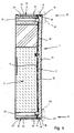
- Die Erfindung ist nachfolgend anhand von in den Zeichnungen veranschaulichten Ausführungsbeispielen näher erläutert. Es zeigen:
- Figur 1
- in der Perspektive eine Breitseitenplatte einer Beam Blank-Kokille von der Gießseite her gesehen;
- Figur 2
- ebenfalls in der Perspektive und von der Gießseite her gesehen eine Kokillenplatte der Breitseitenplatte;
- Figur 3
- in der Perspektive die Rückseite der Kokillenplatte der
Figur 2 ; - Figur 4
- in der Perspektive die Breitseitenplatte der
Figur 1 bei entfernter Kokillenplatte; - Figur 5
- in vergrößerter Darstellung den Ausschnitt V der
Figur 4 ; - Figur 6
- einen vertikalen Querschnitt durch die Darstellung der
Figur 1 entlang der Linie VI-VI in Richtung der Pfeile VIa gesehen; - Figur 7
- in vergrößerter Darstellung den Ausschnitt VII der
Figur 6 und - Figur 8
- in vergrößerter Darstellung den Ausschnitt VIII der
Figur 6 . - In der
Figur 1 ist mit 1 eine Breitseitenplatte für eine nicht näher dargestellte flüssigkeitsgekühlte Beam Blank-Kokille zum Stranggießen von Metallen bezeichnet. Zwei derartige Breitseitenplatten 1 bilden zusammen mit ebenfalls nicht näher dargestellten Schmalseitenplatten den Formhohlraum der Beam Blank-Kokille. - Die Breitseitenplatte 1 setzt sich aus einer dünnwandigen Kokillenplatte 2 und einer die Kokillenplatte 2 tragenden, demgegenüber dickwandigen Adapterplatte 3 zusammen (siehe auch
Figuren 6 bis 8 ). - Wie aus den
Figuren 2 und 3 zu erkennen ist, umfasst die Kokillenplatte 2 einen mittleren Steg 4, sich an den Steg 4 anschließende schräge Schenkel 5 sowie endseitige Flansche 6. Die Übergänge 7, 8 vom Steg 4 auf die Schenkel 5 und von den Schenkeln 5 auf die Flansche 6 sind gerundet. - Auf der Rückseite 9 der Kokillenplatte 2 befinden sich rautenförmige Plateau-Sockel 10, welche der Fixierung von Gewindehülsen 11 dienen, in die aus den
Figuren 4 und 5 erkennbare Befestigungsbolzen 12 zum Verbinden der Kokillenplatte 2 mit der Adapterplatte 3 eingeschraubt werden können. - Ferner ist aus der
Figur 3 ersichtlich, dass auf der Rückseite 9 der Kokillenplatte 2 entlang der konvex gerundeten Übergänge 8 von den Schenkeln 5 auf die Flansche 6 vertikal verlaufende Gleitleisten 13 vorgesehen sind. Die Gleitleisten 13 bilden einen einstückigen Bestandteil der Kokillenplatte 2. Sie erstrecken sich allerdings in diesem Fall über ca. 80 % der Höhe der Kokillenplatte 2. - Am oberen und unteren Rand der Kokillenplatte 2 erstrecken sich auf der Rückseite 9 quer zur Gießrichtung verlaufende Stege 14, die im Bereich der seitlichen Stirnflächen 15 der Kokillenplatte 2 zu deren Rückseite 9 hin schräg auslaufen. Wie bei gemeinsamer Betrachtung der
Figuren 3 und6 bis 8 zu erkennen ist, begrenzen die Stege 14 zusammen mit Randwülsten 16 der Kokillenplatte 2 Längsnuten 17. In die Längsnuten 17 fassen Federn 18, die randseitig von aus denFiguren 1 und4 bis 8 erkennbaren Halteblechen 19 angeordnet sind. Die Haltebleche 19 sind an die Konfiguration der Breitseitenplatte 1 angepasst. Es sind jeweils zwei Haltebleche 19 im Kopf- und Fußbereich 20, 21 der Breitseitenplatte 1 vorgesehen, welche in der vertikalen Mittelquerebene der Breitseitenplatte 1 aneinander stoßen. - Die Haltebleche 19 fassen mit Vorsprüngen 22 in kopf- und fußseitige Ausnehmungen 23, 24 der Adapterplatte 3 ein und sind mit der Adapterplatte 3, wie aus den
Figuren 1 ,4 und 5 ersichtlich ist, verschraubt. Im Ausführungsbeispiel sind je Halteblech 19 fünf Verschraubungen 25 vorgesehen. Die Federn 18 an den Halteblechen 19 sind auf Grund von inneren Aussparungen 26 der Haltebleche 19 gebildet, welche die Stege 14 an der Kokillenplatte 2 und zu den Stegen 14 benachbarte Leisten 27 an der Adapterplatte 3 übergreifen. - Im Bereich der Stege 14 und der Leisten 27 befinden sich in Nuten 28 der Adapterplatte 3 eingesetzte Dichtungen 29. Außerdem ist in
Figur 6 zu erkennen, dass zwischen der Kokillenplatte 2 und der Adapterplatte 3 ein Kühlspalt 30 zur Führung eines Kühlmediums vorgesehen ist. Die Zuführungen 31 für das Kühlmedium sind in denFiguren 6 bis 8 erkennbar. - Analog zu den Gleitleisten 13 der Kokillenplatte 2 sind an der Kühlseite 32 der Adapterplatte 3 (
Figuren 4 und 5 ) im Bereich der Kehlen 33 zwischen den randseitigen Flanschen 34 und den schrägen Schenkeln 35 sich vertikal erstreckende Halteleisten 36 angeordnet. Die Halteleisten 36 sind in Nuten 37 der Kühlseite 32 der Adapterplatte 3 lösbar festgelegt. - Die
Figuren 1 ,6 und8 zeigen, dass im Fußbereich 21 der Kokillenplatte 2 an der Gießseite 39 eine Fase 40 vorgesehen ist. - Auch an den im Fußbereich 21 vorgesehenen Halteblechen 19 befinden sich Fasen 38 an den Federn 18.
-
- 1 -
- Breitseitenplatte
- 2 -
- Kokillenplatte
- 3 -
- Adapterplatte
- 4 -
- Steg v. 2
- 5 -
- Schenkel v. 2
- 6 -
- Flansche v. 2
- 7 -
- Übergänge v. 4 auf 5
- 8 -
- Übergänge v. 5 auf 6
- 9 -
- Rückseite v. 2
- 10 -
- Plateausockel
- 11 -
- Gewindehülsen in 10
- 12 -
- Befestigungsbolzen
- 13 -
- Gleitleisten
- 14 -
- Stege an.2
- 15 -
- Stirnflächen v. 2
- 16 -
- Randwülste v. 2
- 17 -
- Längsnuten
- 18 -
- Federn an 19
- 19 -
- Haltebleche
- 20-
- Kopfbereich v. 1, 2, 3
- 21 -
- Fußbereich v. 1, 2, 3
- 22 -
- Vorsprünge an 19
- 23 -
- obere Ausnehmung in 3
- 24 -
- untere Ausnehmung in 3
- 25 -
- Verschraubungen f. 19
- 26 -
- Aussparungen in 19
- 27 -
- Leisten an 3
- 28 -
- Nuten in 3
- 29 -
- Dichtungen in 28
- 30 -
- Kühlspalt
- 31 -
- Zuführungen zu 30
- 32 -
- Kühlseite v. 3
- 33 -
- Kehlen an 3
- 34 -
- Flansche v. 3
- 35 -
- Schenkel v. 3
- 36 -
- Halteleisten an 3
- 37 -
- Nuten in 33
- 38 -
- Fasen an 19
- 39 -
- Gießseite v. 2
- 40 -
- Fase an 39
Claims (13)
- Flüssigkeitsgekühlte Kokille zum Stranggießen - von Metallen, umfassend Kokillenplatten (2) aus Kupfer oder einer Kupferlegierung und Adapterplatten (3), an welchen die Kokillenplatten (2) über Befestigungsbolzen (12) befestigt sind, dadurch gekennzeichnet, dass die Kokillenplatten (3) zusätzlich zu den Befestigungsbolzen (12) über in ihren Kopf- und Fußbereichen (20, 21) angeordnete Haltebleche (19) mit den Adapterplatten (3) gekoppelt sind.
- Kokille nach Anspruch 1, dadurch gekennzeichnet, dass die Kokillenplatte (2) Bestandteil von Brammen- oder Dünnbrammenkokillen oder Bestandteil einer Breitseitenplatte (1) einer Beam Blank-Kokille ist.
- Kokille nach Anspruch 1 oder 2, dadurch gekennzeichnet, dass die Haltebleche (19) mit Vorsprüngen (22) in kopf- und fußseitige Ausnehmungen (23, 24) der Adapterplatte (3) eingreifen.
- Kokille nach einem der Ansprüche 1 bis 3, dadurch gekennzeichnet, dass die Haltebleche (19) mit der Kokillenplatte (2) über Nut/Federausbildungen (17, 18) gekoppelt sind.
- Kokille nach Anspruch 3, dadurch gekennzeichnet, dass die Kokillenplatte (2) im Kopfbereich (20) und im Fußbereich (21) Längsnuten (17) aufweist, in welche die Haltebleche (19) mit randseitigen Federn (18) eingreifen.
- Kokille nach Anspruch 5, dadurch gekennzeichnet, dass die Längsnuten (17) einerseits von Randwülsten (16) der Kokillenplatte (2) und andererseits von an ihrer Rückseite (9) ausgebildeten Stegen (14) begrenzt sind.
- Kokille nach Anspruch 6, dadurch gekennzeichnet, dass die Stege (14) im Bereich der seitlichen Stirnflächen (15) der Kokillenplatte (2) zu deren Rückseite (9) hin schräg auslaufen.
- Kokille nach Anspruch 6 oder 7, dadurch gekennzeichnet, dass die Federn (18) an den Halteblechen (19) auf Grund von inneren Aussparungen (26) der Haltebleche (19) gebildet sind, welche die Stege (14) an der Kokillenplatte (2) und zu den Stegen (14) benachbarte Leisten (27) an der Adapterplatte (3) übergreifen.
- Kokille nach einem der Ansprüche 1 bis 8, dadurch gekennzeichnet, dass die Kokillenplatte (2) einen mittleren Steg (4), sich an den mittleren Steg (4) anschließende Schenkel (5) und sich an die Schenkel (5) randseitig anschließende Flansche (6) aufweist, wobei sich zwischen den Schenkeln (5) und den Flanschen (6) gerundete Übergänge (8) befinden, wobei die Kokillenplatte (2) auf ihrer Rückseite (9) im Bereich der Übergänge (7) sich in Gießrichtung erstreckende Gleitleisten (13) aufweist, während analog zu den Gleitleisten (13) der Kokillenplatte (2) an einer Kühlseite (32) der Adapterplatte (3) im Bereich von Kehlen (33) zwischen den randseitigen Flanschen (34) und den schrägen Schenkeln (35) sich ebenfalls in Gießrichtung erstreckende Halteleisten (36) angeordnet sind.
- Kokille nach Anspruch 9, dadurch gekennzeichnet, dass die Gleitleisten (13) ein einstückiger Bestandteil der Kokillenplatte (2) sind.
- Kokille nach Anspruch 9 oder 10, dadurch gekennzeichnet, dass die Halteleisten (36) in Nuten (37) der Kühlseite (32) der Adapterplatte (3) lösbar festgelegt sind.
- Kokille nach einem der Ansprüche 1 bis 11, dadurch gekennzeichnet, dass die im Fußbereich (21) vorgesehenen Haltebleche (19) stirnseitig der Federn (18) mit Fasen (38) versehen sind.
- Kokille nach einem der Ansprüche 1 bis 12, dadurch gekennzeichnet, dass die Gießseite (39) der Kokillenplatte (2) im Fußbereich (21) mit einer Fase (40) versehen ist.
Priority Applications (1)
| Application Number | Priority Date | Filing Date | Title |
|---|---|---|---|
| PL08018629T PL2055410T3 (pl) | 2007-11-01 | 2008-10-24 | Chłodzona cieczą forma kokilowa do ciągłego odlewania metali |
Applications Claiming Priority (2)
| Application Number | Priority Date | Filing Date | Title |
|---|---|---|---|
| DE202007015266 | 2007-11-01 | ||
| DE102008007082A DE102008007082A1 (de) | 2007-11-01 | 2008-01-31 | Flüssigkeitsgekühlte Kokille zum Stranggießen von Metallen |
Publications (2)
| Publication Number | Publication Date |
|---|---|
| EP2055410A1 true EP2055410A1 (de) | 2009-05-06 |
| EP2055410B1 EP2055410B1 (de) | 2014-06-18 |
Family
ID=40328451
Family Applications (1)
| Application Number | Title | Priority Date | Filing Date |
|---|---|---|---|
| EP08018629.9A Active EP2055410B1 (de) | 2007-11-01 | 2008-10-24 | Flüssigkeitsgekühlte Kokille zum Stranggießen von Metallen |
Country Status (2)
| Country | Link |
|---|---|
| EP (1) | EP2055410B1 (de) |
| PL (1) | PL2055410T3 (de) |
Citations (3)
| Publication number | Priority date | Publication date | Assignee | Title |
|---|---|---|---|---|
| WO1995021036A1 (en) | 1994-02-02 | 1995-08-10 | Sms Concast Inc. | Mold for continuous casting and method of making the mold |
| EP1013361B1 (de) | 1998-12-21 | 2003-07-16 | KM Europa Metal AG | Kokillenrohr und Verfahren zum Rekalibrieren eines Kokillenrohrs |
| EP1468760A1 (de) | 2003-04-16 | 2004-10-20 | Concast Ag | Rohrkokille zum Stranggiessen |
Family Cites Families (1)
| Publication number | Priority date | Publication date | Assignee | Title |
|---|---|---|---|---|
| FR2800654B1 (fr) * | 1999-11-05 | 2001-12-14 | Lorraine Laminage | Lingotiere a section large pour la coulee continue verticale en charge des metaux |
-
2008
- 2008-10-24 EP EP08018629.9A patent/EP2055410B1/de active Active
- 2008-10-24 PL PL08018629T patent/PL2055410T3/pl unknown
Patent Citations (3)
| Publication number | Priority date | Publication date | Assignee | Title |
|---|---|---|---|---|
| WO1995021036A1 (en) | 1994-02-02 | 1995-08-10 | Sms Concast Inc. | Mold for continuous casting and method of making the mold |
| EP1013361B1 (de) | 1998-12-21 | 2003-07-16 | KM Europa Metal AG | Kokillenrohr und Verfahren zum Rekalibrieren eines Kokillenrohrs |
| EP1468760A1 (de) | 2003-04-16 | 2004-10-20 | Concast Ag | Rohrkokille zum Stranggiessen |
Also Published As
| Publication number | Publication date |
|---|---|
| PL2055410T3 (pl) | 2014-11-28 |
| EP2055410B1 (de) | 2014-06-18 |
Similar Documents
| Publication | Publication Date | Title |
|---|---|---|
| EP2014393B1 (de) | Kokille zum Stranggiessen von Vorblöcken, Brammen oder Knüppeln | |
| DE102008007082A1 (de) | Flüssigkeitsgekühlte Kokille zum Stranggießen von Metallen | |
| EP1472729A1 (de) | Kühlkörper für halbleiterbauelemente oder dgl. einrichtungen, verfahren zu dessen herstellung und werkzeug zur durchführung des verfahrens | |
| EP1792676A1 (de) | Kokille zum Stranggiessen von Metall | |
| EP3487650B1 (de) | Kokillenplatte und kokille | |
| AT403668B (de) | Kokille für stranggiessanlagen | |
| EP2321075A1 (de) | Stranggiesskokille für flüssiges metall, insbesondere für flüssigen stahl | |
| DE1957332A1 (de) | Stranggiesskokille zum Giessen von Metall,insbesondere Stahl | |
| EP0102345B1 (de) | Kokille einer Stranggiessanlage | |
| EP2483017B1 (de) | Giessform | |
| EP2049286A1 (de) | Stranggiesskokille für flüssige metalle, insbesondere für flüssige stahlwerkstoffe | |
| EP2055410B1 (de) | Flüssigkeitsgekühlte Kokille zum Stranggießen von Metallen | |
| EP1007246B1 (de) | Stranggiesskokille | |
| WO2024235396A1 (de) | Kokille | |
| DE1939777B2 (de) | Anordnung und Ausbildung von Übergangsstücken in einer Stranggießkokille | |
| AT17199U1 (de) | Form zum Stranggießen | |
| DE19801728C1 (de) | Stranggießkokille | |
| EP2263815B1 (de) | Kokille zum Stranggiessen von Vorprofilen, insbesondere Doppel-T-Vorprofilen | |
| EP1918042A1 (de) | Stranggiesskokille für Vorprofile | |
| EP3898028B1 (de) | Kokilleneinheit zum stranggiessen von metallprodukten sowie stranggiessanlage | |
| EP1525930B1 (de) | Anfahrvorrichtung für eine Stranggiessanlage | |
| EP1535678B2 (de) | Zusammenbau von Kupferplattenkassetten | |
| WO2019001888A1 (de) | KOKILLENPLATTE UND KOKILLE FÜR EINE STRANGGIEßANLAGE SOWIE STRANGGUSS-VERFAHREN | |
| DE4220523A1 (de) | Verfahren zum Herstellen eines einen Preßabschnitt aufweisenden Werkstücks und Vorrichtung zur Durchführung des Verfahrens | |
| WO2006061046A1 (de) | GIEßFORM ZUM GIEßEN EINES MOTORBLOCKES FUER EINEN VERBRENNUNGSMOTOR, MOTORBLOCK FUER EINEN VERBRENNUNGSMOTOR UND VERWENDUNG EINES HOHLPROFILELEMENTS |
Legal Events
| Date | Code | Title | Description |
|---|---|---|---|
| PUAI | Public reference made under article 153(3) epc to a published international application that has entered the european phase |
Free format text: ORIGINAL CODE: 0009012 |
|
| AK | Designated contracting states |
Kind code of ref document: A1 Designated state(s): AT BE BG CH CY CZ DE DK EE ES FI FR GB GR HR HU IE IS IT LI LT LU LV MC MT NL NO PL PT RO SE SI SK TR |
|
| AX | Request for extension of the european patent |
Extension state: AL BA MK RS |
|
| 17P | Request for examination filed |
Effective date: 20091020 |
|
| AKX | Designation fees paid |
Designated state(s): AT BE BG CH CY CZ DE DK EE ES FI FR GB GR HR HU IE IS IT LI LT LU LV MC MT NL NO PL PT RO SE SI SK TR |
|
| 17Q | First examination report despatched |
Effective date: 20100128 |
|
| RAP1 | Party data changed (applicant data changed or rights of an application transferred) |
Owner name: KME GERMANY GMBH & CO. KG |
|
| GRAP | Despatch of communication of intention to grant a patent |
Free format text: ORIGINAL CODE: EPIDOSNIGR1 |
|
| INTG | Intention to grant announced |
Effective date: 20140129 |
|
| GRAS | Grant fee paid |
Free format text: ORIGINAL CODE: EPIDOSNIGR3 |
|
| GRAA | (expected) grant |
Free format text: ORIGINAL CODE: 0009210 |
|
| AK | Designated contracting states |
Kind code of ref document: B1 Designated state(s): AT BE BG CH CY CZ DE DK EE ES FI FR GB GR HR HU IE IS IT LI LT LU LV MC MT NL NO PL PT RO SE SI SK TR |
|
| REG | Reference to a national code |
Ref country code: GB Ref legal event code: FG4D Free format text: NOT ENGLISH |
|
| REG | Reference to a national code |
Ref country code: CH Ref legal event code: EP |
|
| REG | Reference to a national code |
Ref country code: AT Ref legal event code: REF Ref document number: 673042 Country of ref document: AT Kind code of ref document: T Effective date: 20140715 Ref country code: CH Ref legal event code: NV Representative=s name: ALDO ROEMPLER PATENTANWALT, CH |
|
| REG | Reference to a national code |
Ref country code: IE Ref legal event code: FG4D Free format text: LANGUAGE OF EP DOCUMENT: GERMAN |
|
| REG | Reference to a national code |
Ref country code: DE Ref legal event code: R096 Ref document number: 502008011891 Country of ref document: DE Effective date: 20140731 |
|
| REG | Reference to a national code |
Ref country code: NL Ref legal event code: T3 |
|
| REG | Reference to a national code |
Ref country code: ES Ref legal event code: FG2A Ref document number: 2502891 Country of ref document: ES Kind code of ref document: T3 Effective date: 20141006 |
|
| PG25 | Lapsed in a contracting state [announced via postgrant information from national office to epo] |
Ref country code: CY Free format text: LAPSE BECAUSE OF FAILURE TO SUBMIT A TRANSLATION OF THE DESCRIPTION OR TO PAY THE FEE WITHIN THE PRESCRIBED TIME-LIMIT Effective date: 20140618 Ref country code: LT Free format text: LAPSE BECAUSE OF FAILURE TO SUBMIT A TRANSLATION OF THE DESCRIPTION OR TO PAY THE FEE WITHIN THE PRESCRIBED TIME-LIMIT Effective date: 20140618 Ref country code: FI Free format text: LAPSE BECAUSE OF FAILURE TO SUBMIT A TRANSLATION OF THE DESCRIPTION OR TO PAY THE FEE WITHIN THE PRESCRIBED TIME-LIMIT Effective date: 20140618 Ref country code: GR Free format text: LAPSE BECAUSE OF FAILURE TO SUBMIT A TRANSLATION OF THE DESCRIPTION OR TO PAY THE FEE WITHIN THE PRESCRIBED TIME-LIMIT Effective date: 20140919 Ref country code: NO Free format text: LAPSE BECAUSE OF FAILURE TO SUBMIT A TRANSLATION OF THE DESCRIPTION OR TO PAY THE FEE WITHIN THE PRESCRIBED TIME-LIMIT Effective date: 20140918 |
|
| REG | Reference to a national code |
Ref country code: LT Ref legal event code: MG4D |
|
| PG25 | Lapsed in a contracting state [announced via postgrant information from national office to epo] |
Ref country code: HR Free format text: LAPSE BECAUSE OF FAILURE TO SUBMIT A TRANSLATION OF THE DESCRIPTION OR TO PAY THE FEE WITHIN THE PRESCRIBED TIME-LIMIT Effective date: 20140618 Ref country code: LV Free format text: LAPSE BECAUSE OF FAILURE TO SUBMIT A TRANSLATION OF THE DESCRIPTION OR TO PAY THE FEE WITHIN THE PRESCRIBED TIME-LIMIT Effective date: 20140618 Ref country code: SE Free format text: LAPSE BECAUSE OF FAILURE TO SUBMIT A TRANSLATION OF THE DESCRIPTION OR TO PAY THE FEE WITHIN THE PRESCRIBED TIME-LIMIT Effective date: 20140618 |
|
| REG | Reference to a national code |
Ref country code: PL Ref legal event code: T3 |
|
| PG25 | Lapsed in a contracting state [announced via postgrant information from national office to epo] |
Ref country code: PT Free format text: LAPSE BECAUSE OF FAILURE TO SUBMIT A TRANSLATION OF THE DESCRIPTION OR TO PAY THE FEE WITHIN THE PRESCRIBED TIME-LIMIT Effective date: 20141020 Ref country code: CZ Free format text: LAPSE BECAUSE OF FAILURE TO SUBMIT A TRANSLATION OF THE DESCRIPTION OR TO PAY THE FEE WITHIN THE PRESCRIBED TIME-LIMIT Effective date: 20140618 Ref country code: RO Free format text: LAPSE BECAUSE OF FAILURE TO SUBMIT A TRANSLATION OF THE DESCRIPTION OR TO PAY THE FEE WITHIN THE PRESCRIBED TIME-LIMIT Effective date: 20140618 Ref country code: SK Free format text: LAPSE BECAUSE OF FAILURE TO SUBMIT A TRANSLATION OF THE DESCRIPTION OR TO PAY THE FEE WITHIN THE PRESCRIBED TIME-LIMIT Effective date: 20140618 Ref country code: EE Free format text: LAPSE BECAUSE OF FAILURE TO SUBMIT A TRANSLATION OF THE DESCRIPTION OR TO PAY THE FEE WITHIN THE PRESCRIBED TIME-LIMIT Effective date: 20140618 |
|
| PG25 | Lapsed in a contracting state [announced via postgrant information from national office to epo] |
Ref country code: IS Free format text: LAPSE BECAUSE OF FAILURE TO SUBMIT A TRANSLATION OF THE DESCRIPTION OR TO PAY THE FEE WITHIN THE PRESCRIBED TIME-LIMIT Effective date: 20141018 |
|
| REG | Reference to a national code |
Ref country code: DE Ref legal event code: R097 Ref document number: 502008011891 Country of ref document: DE |
|
| PLBE | No opposition filed within time limit |
Free format text: ORIGINAL CODE: 0009261 |
|
| STAA | Information on the status of an ep patent application or granted ep patent |
Free format text: STATUS: NO OPPOSITION FILED WITHIN TIME LIMIT |
|
| PG25 | Lapsed in a contracting state [announced via postgrant information from national office to epo] |
Ref country code: DK Free format text: LAPSE BECAUSE OF FAILURE TO SUBMIT A TRANSLATION OF THE DESCRIPTION OR TO PAY THE FEE WITHIN THE PRESCRIBED TIME-LIMIT Effective date: 20140618 |
|
| 26N | No opposition filed |
Effective date: 20150319 |
|
| PG25 | Lapsed in a contracting state [announced via postgrant information from national office to epo] |
Ref country code: MC Free format text: LAPSE BECAUSE OF FAILURE TO SUBMIT A TRANSLATION OF THE DESCRIPTION OR TO PAY THE FEE WITHIN THE PRESCRIBED TIME-LIMIT Effective date: 20140618 |
|
| PG25 | Lapsed in a contracting state [announced via postgrant information from national office to epo] |
Ref country code: BE Free format text: LAPSE BECAUSE OF NON-PAYMENT OF DUE FEES Effective date: 20141031 |
|
| REG | Reference to a national code |
Ref country code: IE Ref legal event code: MM4A |
|
| PG25 | Lapsed in a contracting state [announced via postgrant information from national office to epo] |
Ref country code: SI Free format text: LAPSE BECAUSE OF FAILURE TO SUBMIT A TRANSLATION OF THE DESCRIPTION OR TO PAY THE FEE WITHIN THE PRESCRIBED TIME-LIMIT Effective date: 20140618 |
|
| PG25 | Lapsed in a contracting state [announced via postgrant information from national office to epo] |
Ref country code: IE Free format text: LAPSE BECAUSE OF NON-PAYMENT OF DUE FEES Effective date: 20141024 |
|
| REG | Reference to a national code |
Ref country code: FR Ref legal event code: PLFP Year of fee payment: 8 |
|
| PGFP | Annual fee paid to national office [announced via postgrant information from national office to epo] |
Ref country code: GB Payment date: 20151030 Year of fee payment: 8 |
|
| PGFP | Annual fee paid to national office [announced via postgrant information from national office to epo] |
Ref country code: ES Payment date: 20151126 Year of fee payment: 8 Ref country code: FR Payment date: 20151030 Year of fee payment: 8 Ref country code: PL Payment date: 20151022 Year of fee payment: 8 |
|
| PG25 | Lapsed in a contracting state [announced via postgrant information from national office to epo] |
Ref country code: BG Free format text: LAPSE BECAUSE OF FAILURE TO SUBMIT A TRANSLATION OF THE DESCRIPTION OR TO PAY THE FEE WITHIN THE PRESCRIBED TIME-LIMIT Effective date: 20140618 |
|
| PG25 | Lapsed in a contracting state [announced via postgrant information from national office to epo] |
Ref country code: HU Free format text: LAPSE BECAUSE OF FAILURE TO SUBMIT A TRANSLATION OF THE DESCRIPTION OR TO PAY THE FEE WITHIN THE PRESCRIBED TIME-LIMIT; INVALID AB INITIO Effective date: 20081024 Ref country code: MT Free format text: LAPSE BECAUSE OF FAILURE TO SUBMIT A TRANSLATION OF THE DESCRIPTION OR TO PAY THE FEE WITHIN THE PRESCRIBED TIME-LIMIT Effective date: 20140618 |
|
| GBPC | Gb: european patent ceased through non-payment of renewal fee |
Effective date: 20161024 |
|
| REG | Reference to a national code |
Ref country code: FR Ref legal event code: ST Effective date: 20170630 |
|
| PG25 | Lapsed in a contracting state [announced via postgrant information from national office to epo] |
Ref country code: GB Free format text: LAPSE BECAUSE OF NON-PAYMENT OF DUE FEES Effective date: 20161024 Ref country code: FR Free format text: LAPSE BECAUSE OF NON-PAYMENT OF DUE FEES Effective date: 20161102 |
|
| PG25 | Lapsed in a contracting state [announced via postgrant information from national office to epo] |
Ref country code: PL Free format text: LAPSE BECAUSE OF NON-PAYMENT OF DUE FEES Effective date: 20161024 |
|
| PG25 | Lapsed in a contracting state [announced via postgrant information from national office to epo] |
Ref country code: ES Free format text: LAPSE BECAUSE OF NON-PAYMENT OF DUE FEES Effective date: 20161025 |
|
| REG | Reference to a national code |
Ref country code: ES Ref legal event code: FD2A Effective date: 20180626 |
|
| REG | Reference to a national code |
Ref country code: DE Ref legal event code: R081 Ref document number: 502008011891 Country of ref document: DE Owner name: CUNOVA GMBH, DE Free format text: FORMER OWNER: KME GERMANY GMBH & CO. KG, 49074 OSNABRUECK, DE Ref country code: DE Ref legal event code: R081 Ref document number: 502008011891 Country of ref document: DE Owner name: KME SPECIAL PRODUCTS & SOLUTIONS GMBH, DE Free format text: FORMER OWNER: KME GERMANY GMBH & CO. KG, 49074 OSNABRUECK, DE |
|
| REG | Reference to a national code |
Ref country code: DE Ref legal event code: R081 Ref document number: 502008011891 Country of ref document: DE Owner name: CUNOVA GMBH, DE Free format text: FORMER OWNER: KME SPECIAL PRODUCTS GMBH & CO. KG, 49074 OSNABRUECK, DE Ref country code: DE Ref legal event code: R081 Ref document number: 502008011891 Country of ref document: DE Owner name: KME SPECIAL PRODUCTS & SOLUTIONS GMBH, DE Free format text: FORMER OWNER: KME SPECIAL PRODUCTS GMBH & CO. KG, 49074 OSNABRUECK, DE |
|
| REG | Reference to a national code |
Ref country code: DE Ref legal event code: R081 Ref document number: 502008011891 Country of ref document: DE Owner name: CUNOVA GMBH, DE Free format text: FORMER OWNER: KME SPECIAL PRODUCTS & SOLUTIONS GMBH, 49074 OSNABRUECK, DE |
|
| REG | Reference to a national code |
Ref country code: NL Ref legal event code: PD Owner name: CUNOVA GMBH; DE Free format text: DETAILS ASSIGNMENT: CHANGE OF OWNER(S), ASSIGNMENT; FORMER OWNER NAME: KME SPECIAL PRODUCTS GMBH Effective date: 20241127 Ref country code: NL Ref legal event code: HC Owner name: KME SPECIAL PRODUCTS GMBH; DE Free format text: DETAILS ASSIGNMENT: CHANGE OF OWNER(S), CHANGE OF OWNER(S) NAME; FORMER OWNER NAME: KME GERMANY GMBH Effective date: 20241127 |
|
| REG | Reference to a national code |
Ref country code: AT Ref legal event code: PC Ref document number: 673042 Country of ref document: AT Kind code of ref document: T Owner name: CUNOVA GMBH, DE Effective date: 20250428 |
|
| REG | Reference to a national code |
Ref country code: CH Ref legal event code: U11 Free format text: ST27 STATUS EVENT CODE: U-0-0-U10-U11 (AS PROVIDED BY THE NATIONAL OFFICE) Effective date: 20251101 |
|
| PGFP | Annual fee paid to national office [announced via postgrant information from national office to epo] |
Ref country code: NL Payment date: 20251024 Year of fee payment: 18 Ref country code: LU Payment date: 20251024 Year of fee payment: 18 |
|
| PGFP | Annual fee paid to national office [announced via postgrant information from national office to epo] |
Ref country code: DE Payment date: 20251028 Year of fee payment: 18 |
|
| PGFP | Annual fee paid to national office [announced via postgrant information from national office to epo] |
Ref country code: AT Payment date: 20251020 Year of fee payment: 18 |
|
| PGFP | Annual fee paid to national office [announced via postgrant information from national office to epo] |
Ref country code: IT Payment date: 20251022 Year of fee payment: 18 |
|
| PGFP | Annual fee paid to national office [announced via postgrant information from national office to epo] |
Ref country code: TR Payment date: 20251010 Year of fee payment: 18 |
|
| PGFP | Annual fee paid to national office [announced via postgrant information from national office to epo] |
Ref country code: CH Payment date: 20251101 Year of fee payment: 18 |