EP2053252B1 - Dispositif hydraulique destiné à la commande d'au moins un composant de véhicule - Google Patents
Dispositif hydraulique destiné à la commande d'au moins un composant de véhicule Download PDFInfo
- Publication number
- EP2053252B1 EP2053252B1 EP08017112.7A EP08017112A EP2053252B1 EP 2053252 B1 EP2053252 B1 EP 2053252B1 EP 08017112 A EP08017112 A EP 08017112A EP 2053252 B1 EP2053252 B1 EP 2053252B1
- Authority
- EP
- European Patent Office
- Prior art keywords
- housing
- piston
- hydraulic arrangement
- piston rod
- arrangement according
- Prior art date
- Legal status (The legal status is an assumption and is not a legal conclusion. Google has not performed a legal analysis and makes no representation as to the accuracy of the status listed.)
- Not-in-force
Links
Images

Classifications
-
- F—MECHANICAL ENGINEERING; LIGHTING; HEATING; WEAPONS; BLASTING
- F15—FLUID-PRESSURE ACTUATORS; HYDRAULICS OR PNEUMATICS IN GENERAL
- F15B—SYSTEMS ACTING BY MEANS OF FLUIDS IN GENERAL; FLUID-PRESSURE ACTUATORS, e.g. SERVOMOTORS; DETAILS OF FLUID-PRESSURE SYSTEMS, NOT OTHERWISE PROVIDED FOR
- F15B7/00—Systems in which the movement produced is definitely related to the output of a volumetric pump; Telemotors
- F15B7/06—Details
- F15B7/08—Input units; Master units
-
- F—MECHANICAL ENGINEERING; LIGHTING; HEATING; WEAPONS; BLASTING
- F16—ENGINEERING ELEMENTS AND UNITS; GENERAL MEASURES FOR PRODUCING AND MAINTAINING EFFECTIVE FUNCTIONING OF MACHINES OR INSTALLATIONS; THERMAL INSULATION IN GENERAL
- F16D—COUPLINGS FOR TRANSMITTING ROTATION; CLUTCHES; BRAKES
- F16D25/00—Fluid-actuated clutches
- F16D25/08—Fluid-actuated clutches with fluid-actuated member not rotating with a clutching member
- F16D2025/081—Hydraulic devices that initiate movement of pistons in slave cylinders for actuating clutches, i.e. master cylinders
Definitions
- the present invention relates to a hydraulic system for driving at least one component of a vehicle according to the preamble of claim 1.
- the present invention relates to a hydraulic arrangement with a master cylinder comprising a pressure chamber formed in its housing, in which a displaceable piston is movable, wherein Limiting the extension movement of the piston, at least one stop is provided, which cooperates with a piston-side stop.
- a hydraulic system for a motor vehicle comprising a master cylinder with a housing and a piston arranged axially displaceably in this.
- the piston delimits a filled with a hydraulic fluid pressure chamber and is axially displaced upon actuation of the master cylinder by means of a piston rod acting on the piston, wherein the piston rod is connected via a ball joint with the piston.
- the pressure chamber of the master cylinder is connected via a pressure line with a slave cylinder. With the slave cylinder a releaser of a clutch is actuated via a release mechanism.
- a stop plate is arranged on the side facing away from the piston of the ball joint.
- the movement of the piston is limited by a retaining clip backwards by the stopper plate abuts the retaining clip. In this way, an effective in the pulling direction stop exists.
- the retaining clip is attached in the known hydraulic arrangement to a welding ring. The welding ring in turn receives the piston for axial guidance and is welded to the housing.
- the piston rod of the master cylinder has to transmit a pull-out force of up to 1500 Newtons.
- This pull-out force is transmitted through the stop or the retaining clip and the welding ring on the housing. Therefore, the weld must be made very robust in the known hydraulic arrangement, so that destruction of this compound is prevented in extreme pedal operations.
- a hydraulic system according to the preamble of claim 1 is known from DE 103 51 907 A1 known.
- the present invention is based on the object to propose a hydraulic system of the type described above, which ensures the safest possible operation and in the installation space and installation adjustments without extensive changes are possible.
- the housing is designed in several parts, the pull-out force is absorbed, for example, in a pedal stop directly from the housing parts.
- the connection between the welding ring and the housing is not acted upon by the pull-out force, so that this connection does not have to be made additionally robust.
- the welding ring as an inner component in a space or installation adjustment does not need to be adjusted. This results in a significant reduction of the required modification effort, since only the housing parts may be changed as external parts.
- the welding ring can be standardized, so as to be able to save development costs and development time. Any change requests to the master cylinder can be carried out quickly, because only the housing is provided as an outer part.
- the housing part associated with the piston rod has recesses or the like in the radial direction for receiving a retaining element.
- the housing part is connected to an additional holding element in order to jointly form the housing-side stop area.
- the holding element may extend in the radial direction through the housing.
- the retaining element can be releasably retained in recesses or the like of the housing. In this case, for example, positive or non-positive connections can be used.
- the holding element is preferably designed as a roughly U-shaped retaining clip or the like.
- the retaining clip for example, can be inserted radially through the housing part associated with the piston rod in the region of the piston rod, thus forming a housing-side stop region for the piston.
- the two legs of the U-shaped retaining clip have a distance between each other, which is at least slightly smaller than the diameter of a stop plate designed as a piston-side stop. In this way, the two legs form a housing-side stop for the stop plate.
- the shape of the stop plate can be chosen arbitrarily.
- the stop plate may be attached to the piston rod. There are also other possible arrangements of the stop plate conceivable.
- the distance is at least slightly greater than the diameter of the piston rod.
- the piston rod associated with the housing part is releasably connected as a lid to the housing base part. It is also conceivable that further housing parts are provided. As a releasable connection may preferably be provided a snap ring connection or a bayonet closure. However, other types of connection are conceivable.
- the hydraulic system can preferably be used for driving a clutch.
- other applications are conceivable.
- the hydraulic arrangement comprises a master cylinder 1, which has a multi-part housing with a housing base part 2 and a further housing part 3 as cover. By the housing, a pressure chamber 16 is formed.
- a pressure medium connection 18 is arranged, which is connected to a pressure medium line, not shown, which leads to a slave cylinder also not shown for driving the clutch.
- the housing base part 2 and the housing part 3 are connected to each other via a detachable connection, for example via a snap-in connection or a bayonet closure.
- the connecting piece 4 is connected to a pressure medium reservoir, not shown, can run from the pressure medium.
- an axially displaceable piston 5 is arranged in the filled with a hydraulic fluid pressure chamber 16, an axially displaceable piston 5 is arranged.
- the piston 5 Upon actuation of the master cylinder 1, the piston 5 is displaced axially against the spring force of a return spring 9 via a piston rod 5 fastened to the piston 5, in order to produce a corresponding pressure in the slave cylinder for actuating the clutch applied.
- the axial movement of the piston 5 is supported by a welding ring 10 which is fixed to the housing 2.
- a stop plate 7 for limiting the extension movement of the piston 5, e.g. arranged on the piston rod 6 a stop plate 7 as a piston-side stop, which cooperates with a housing-side stop.
- the housing-side stop is realized by a stopper portion 15 on the housing part 3.
- the axial stop region 15 corresponds to the stop plate 7 designed as a piston-side stop, so that the retraction movement of the piston 5 is correspondingly limited.
- the stop area 15 also has an axial passage 17 for the piston rod 6.
- the passage 17 is formed as a slot whose width is at least slightly larger than the diameter of the piston rod 6 and at least slightly smaller than the diameter of the stop plate 7.
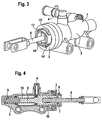
- the housing-side stop is in the embodiment according to the FIGS. 3 and 4 realized by a holding element which is connected to the housing part 3.
- the holding element is designed as an approximately U-shaped retaining clip 8.
- the retaining clip 8 is with their legs through corresponding recesses 13, 13 '; 14, 14 'guided at the top and at the bottom of the housing part 3 to extend radially through the housing part 3.
- the distance between the two legs is at least slightly smaller than the diameter of the stop plate 7, so that the extension movement of the piston 5 is limited. In this case, the distance between the two legs is slightly larger than the diameter of the piston rod 6 in order to allow the piston rod 6 to be freely movable between the legs.
- the retaining clip 8 is connected directly to the housing part 3 of the master cylinder 1, so that the pull-out force is transmitted upon reaching the stop directly from the retaining clip 8 to the housing.
- the assembly process is thereby hardly affected because the retaining clip 8 is inserted directly into the housing part 3.
- the housing part 3 provided as cover is fastened to the housing base part 2 via a detachable connection.
Claims (7)
- Agencement hydraulique pour la commande d'au moins un composant d'un véhicule, comprenant un maître-cylindre (1) qui comprend un espace de pression (16) formé dans son boîtier, dans lequel peut se déplacer un piston déplaçable (5), au moins une butée étant prévue pour limiter le mouvement de sortie du piston (5), laquelle coopère avec une butée du côté du piston, le boîtier étant réalisé en plusieurs parties et la partie de boîtier (3) associée à une tige de piston (6) étant prévue sous forme de butée du côté du boîtier, caractérisé en ce que la partie de boîtier (3) associée à la tige de piston (6) présente des évidements (13, 13' ; 14, 14') dans la direction radiale pour recevoir un élément de retenue.
- Agencement hydraulique selon la revendication 1, caractérisé en ce que l'élément de retenue est réalisé sous forme de pince de retenue (8) ayant approximativement une forme en U.
- Agencement hydraulique selon la revendication 2, caractérisé en ce que les deux branches de la pince de retenue (8) en forme de U forment avec la partie de boîtier (3) la butée du côté du boîtier pour un plateau de butée (7) du côté du piston.
- Agencement hydraulique selon la revendication 3, caractérisé en ce que la distance entre les branches de la pince de retenue (8) en forme de U est au moins légèrement inférieure au diamètre du plateau de butée (7).
- Agencement hydraulique selon l'une quelconque des revendications 2 à 4, caractérisé en ce que la distance entre les deux branches de la pince de retenue (8) en forme de U est au moins légèrement supérieure au diamètre de la tige de piston (6).
- Agencement hydraulique selon l'une quelconque des revendications précédentes, caractérisé en ce que la partie de boîtier (3) associée à la tige de piston (6) est connectée de manière détachable en tant que couvercle à une partie de base de boîtier (2).
- Agencement hydraulique selon la revendication 6, caractérisé en ce que la connexion détachable est réalisée sous forme de connexion par encliquetage ou de fermeture à baïonnette.
Applications Claiming Priority (1)
| Application Number | Priority Date | Filing Date | Title |
|---|---|---|---|
| DE102007051066 | 2007-10-25 |
Publications (3)
| Publication Number | Publication Date |
|---|---|
| EP2053252A2 EP2053252A2 (fr) | 2009-04-29 |
| EP2053252A3 EP2053252A3 (fr) | 2012-08-08 |
| EP2053252B1 true EP2053252B1 (fr) | 2013-11-27 |
Family
ID=40259133
Family Applications (1)
| Application Number | Title | Priority Date | Filing Date |
|---|---|---|---|
| EP08017112.7A Not-in-force EP2053252B1 (fr) | 2007-10-25 | 2008-09-29 | Dispositif hydraulique destiné à la commande d'au moins un composant de véhicule |
Country Status (2)
| Country | Link |
|---|---|
| EP (1) | EP2053252B1 (fr) |
| DE (1) | DE102008049424A1 (fr) |
Cited By (3)
| Publication number | Priority date | Publication date | Assignee | Title |
|---|---|---|---|---|
| DE102016216994A1 (de) | 2016-09-07 | 2018-03-08 | Schaeffler Technologies AG & Co. KG | Geberzylinder mit einer montagevereinfachenden Einführfase |
| DE102021122699A1 (de) | 2021-09-02 | 2023-03-02 | Schaeffler Technologies AG & Co. KG | Hydraulikzylinder |
| DE102021122718A1 (de) | 2021-09-02 | 2023-03-02 | Schaeffler Technologies AG & Co. KG | Geberzylinder |
Families Citing this family (2)
| Publication number | Priority date | Publication date | Assignee | Title |
|---|---|---|---|---|
| JP6049695B2 (ja) * | 2011-04-27 | 2016-12-21 | シェフラー テクノロジーズ アー・ゲー ウント コー. カー・ゲーSchaeffler Technologies AG & Co. KG | マスタシリンダ及びマスタシリンダの組付け方法 |
| DE102016219768A1 (de) | 2016-10-12 | 2018-04-12 | Schaeffler Technologies AG & Co. KG | Kupplungsgeberzylinder mit einem in einen Hohlraum einer Kolbenstange eingreifenden Anschlag |
Family Cites Families (7)
| Publication number | Priority date | Publication date | Assignee | Title |
|---|---|---|---|---|
| US4162616A (en) * | 1976-04-02 | 1979-07-31 | Tokico Ltd. | Hydraulic master cylinder |
| US4510752A (en) * | 1981-07-10 | 1985-04-16 | The Bendix Corporation | Master cylinder |
| DE3149628A1 (de) * | 1981-12-15 | 1983-07-21 | FAG Kugelfischer Georg Schäfer & Co, 8720 Schweinfurt | Kugelgelenkverbindung |
| DE20208568U1 (de) * | 2002-06-03 | 2002-08-29 | Fte Automotive Gmbh | Hydraulikzylinder |
| DE10327437A1 (de) | 2002-06-24 | 2004-01-22 | Luk Lamellen Und Kupplungsbau Beteiligungs Kg | Hydraulisches System |
| DE10351907B4 (de) * | 2002-11-12 | 2016-09-22 | Schaeffler Technologies AG & Co. KG | Hydraulisches System |
| JP2004278639A (ja) * | 2003-03-14 | 2004-10-07 | Nabco Ltd | 脈動吸収装置およびクラッチマスタシリンダ |
-
2008
- 2008-09-29 EP EP08017112.7A patent/EP2053252B1/fr not_active Not-in-force
- 2008-09-29 DE DE102008049424A patent/DE102008049424A1/de not_active Withdrawn
Cited By (3)
| Publication number | Priority date | Publication date | Assignee | Title |
|---|---|---|---|---|
| DE102016216994A1 (de) | 2016-09-07 | 2018-03-08 | Schaeffler Technologies AG & Co. KG | Geberzylinder mit einer montagevereinfachenden Einführfase |
| DE102021122699A1 (de) | 2021-09-02 | 2023-03-02 | Schaeffler Technologies AG & Co. KG | Hydraulikzylinder |
| DE102021122718A1 (de) | 2021-09-02 | 2023-03-02 | Schaeffler Technologies AG & Co. KG | Geberzylinder |
Also Published As
| Publication number | Publication date |
|---|---|
| DE102008049424A1 (de) | 2009-04-30 |
| EP2053252A2 (fr) | 2009-04-29 |
| EP2053252A3 (fr) | 2012-08-08 |
Similar Documents
| Publication | Publication Date | Title |
|---|---|---|
| EP3515766B1 (fr) | Ensemble de frein pour un système de freinage d'un véhicule | |
| EP2053252B1 (fr) | Dispositif hydraulique destiné à la commande d'au moins un composant de véhicule | |
| EP1512882B1 (fr) | Cylindre hydraulique | |
| EP3509920B1 (fr) | Appareil de freinage pour un frein hydraulique d'un vehichle | |
| WO2012155884A1 (fr) | Dispositif de débrayage à actionnement hydraulique, comportant un carter composé de plusieurs pièces | |
| EP3380373B1 (fr) | Dispositif de frein pour système de freinage hydraulique d'un vehicule | |
| EP1706302B1 (fr) | Maitre-cylindre destine en particulier a un systeme de freinage regule | |
| DE102009050346A1 (de) | Kupplungsausrücksystem mit Verdrehsicherung für Nehmerzylinderkolben | |
| DE102007008724B4 (de) | Scheibenbremse, insbesondere für ein Nutzfahrzeug | |
| DE102008050292A1 (de) | Hydraulikanordnung zum Ansteuern zumindest einer Komponente eines Fahrzeuges | |
| DE112013004714B4 (de) | Nehmerzylinder eines Ausrücksystems für Kupplungs- oder Bremssysteme | |
| WO2017089234A1 (fr) | Dispositif de freinage pour un système de freinage hydraulique de véhicule à moteur | |
| WO2009092463A1 (fr) | Système de vérin pour un actionneur d’embrayage commandé par un fluide sous pression | |
| DE102004013662B4 (de) | Hauptbremszylinder mit integrierter Transportsicherung | |
| EP1487683B1 (fr) | Unite piston comportant un ressort bloque | |
| DE102008035179A1 (de) | Bremskrafterzeuger für eine Kraftfahrzeugbremsanlage mit Stützeinrichtung für Rückstellfeder | |
| DE102013222066A1 (de) | Kolben-Zylinder-Einheit | |
| DE10054251B4 (de) | Steuerventilgehäuse für einen Unterdruck-Bremskraftverstärker | |
| EP2459424B1 (fr) | Maître-cylindre en particulier pour un système de freinage à régulation d'un véhicule à moteur | |
| DE102016202035B3 (de) | Betätigungszylinder mit an ihm befestigten Faltenbalg | |
| DE102017117280A1 (de) | Hydraulisches Kupplungsbetätigungssystem mit Staubschutz | |
| DE102016213904B4 (de) | Kolben-Zylinder-Einheit | |
| EP3749876B1 (fr) | Cylindre récepteur muni d'un piston conçu pour réduire l'usure, dispositif d'actionnement et système d'embrayage | |
| EP2379387B1 (fr) | Amplificateur pneumatique de force de freinage pour un système de freinage d'un véhicule | |
| DE102008053363A1 (de) | Hydraulikzylinder |
Legal Events
| Date | Code | Title | Description |
|---|---|---|---|
| PUAI | Public reference made under article 153(3) epc to a published international application that has entered the european phase |
Free format text: ORIGINAL CODE: 0009012 |
|
| AK | Designated contracting states |
Kind code of ref document: A2 Designated state(s): AT BE BG CH CY CZ DE DK EE ES FI FR GB GR HR HU IE IS IT LI LT LU LV MC MT NL NO PL PT RO SE SI SK TR |
|
| AX | Request for extension of the european patent |
Extension state: AL BA MK RS |
|
| RAP1 | Party data changed (applicant data changed or rights of an application transferred) |
Owner name: SCHAEFFLER TECHNOLOGIES AG & CO. KG |
|
| PUAL | Search report despatched |
Free format text: ORIGINAL CODE: 0009013 |
|
| AK | Designated contracting states |
Kind code of ref document: A3 Designated state(s): AT BE BG CH CY CZ DE DK EE ES FI FR GB GR HR HU IE IS IT LI LT LU LV MC MT NL NO PL PT RO SE SI SK TR |
|
| AX | Request for extension of the european patent |
Extension state: AL BA MK RS |
|
| RIC1 | Information provided on ipc code assigned before grant |
Ipc: F16D 25/08 20060101ALI20120629BHEP Ipc: F15B 7/08 20060101AFI20120629BHEP |
|
| 17P | Request for examination filed |
Effective date: 20130208 |
|
| AKX | Designation fees paid |
Designated state(s): AT BE BG CH CY CZ DE DK EE ES FI FR GB GR HR HU IE IS IT LI LT LU LV MC MT NL NO PL PT RO SE SI SK TR |
|
| RIC1 | Information provided on ipc code assigned before grant |
Ipc: F16D 25/08 20060101ALI20130312BHEP Ipc: F15B 7/08 20060101AFI20130312BHEP |
|
| GRAP | Despatch of communication of intention to grant a patent |
Free format text: ORIGINAL CODE: EPIDOSNIGR1 |
|
| INTG | Intention to grant announced |
Effective date: 20130701 |
|
| GRAS | Grant fee paid |
Free format text: ORIGINAL CODE: EPIDOSNIGR3 |
|
| GRAA | (expected) grant |
Free format text: ORIGINAL CODE: 0009210 |
|
| AK | Designated contracting states |
Kind code of ref document: B1 Designated state(s): AT BE BG CH CY CZ DE DK EE ES FI FR GB GR HR HU IE IS IT LI LT LU LV MC MT NL NO PL PT RO SE SI SK TR |
|
| REG | Reference to a national code |
Ref country code: GB Ref legal event code: FG4D Free format text: NOT ENGLISH |
|
| REG | Reference to a national code |
Ref country code: CH Ref legal event code: EP |
|
| REG | Reference to a national code |
Ref country code: AT Ref legal event code: REF Ref document number: 642841 Country of ref document: AT Kind code of ref document: T Effective date: 20131215 |
|
| REG | Reference to a national code |
Ref country code: IE Ref legal event code: FG4D Free format text: LANGUAGE OF EP DOCUMENT: GERMAN |
|
| REG | Reference to a national code |
Ref country code: DE Ref legal event code: R096 Ref document number: 502008011005 Country of ref document: DE Effective date: 20140123 |
|
| RAP2 | Party data changed (patent owner data changed or rights of a patent transferred) |
Owner name: SCHAEFFLER TECHNOLOGIES GMBH & CO. KG |
|
| REG | Reference to a national code |
Ref country code: NL Ref legal event code: VDEP Effective date: 20131127 |
|
| REG | Reference to a national code |
Ref country code: DE Ref legal event code: R081 Ref document number: 502008011005 Country of ref document: DE Owner name: SCHAEFFLER TECHNOLOGIES GMBH & CO. KG, DE Free format text: FORMER OWNER: SCHAEFFLER TECHNOLOGIES AG & CO. KG, 91074 HERZOGENAURACH, DE Effective date: 20140214 Ref country code: DE Ref legal event code: R081 Ref document number: 502008011005 Country of ref document: DE Owner name: SCHAEFFLER TECHNOLOGIES AG & CO. KG, DE Free format text: FORMER OWNER: SCHAEFFLER TECHNOLOGIES AG & CO. KG, 91074 HERZOGENAURACH, DE Effective date: 20140214 |
|
| REG | Reference to a national code |
Ref country code: LT Ref legal event code: MG4D |
|
| PG25 | Lapsed in a contracting state [announced via postgrant information from national office to epo] |
Ref country code: NO Free format text: LAPSE BECAUSE OF FAILURE TO SUBMIT A TRANSLATION OF THE DESCRIPTION OR TO PAY THE FEE WITHIN THE PRESCRIBED TIME-LIMIT Effective date: 20140227 Ref country code: IS Free format text: LAPSE BECAUSE OF FAILURE TO SUBMIT A TRANSLATION OF THE DESCRIPTION OR TO PAY THE FEE WITHIN THE PRESCRIBED TIME-LIMIT Effective date: 20140327 Ref country code: LT Free format text: LAPSE BECAUSE OF FAILURE TO SUBMIT A TRANSLATION OF THE DESCRIPTION OR TO PAY THE FEE WITHIN THE PRESCRIBED TIME-LIMIT Effective date: 20131127 Ref country code: HR Free format text: LAPSE BECAUSE OF FAILURE TO SUBMIT A TRANSLATION OF THE DESCRIPTION OR TO PAY THE FEE WITHIN THE PRESCRIBED TIME-LIMIT Effective date: 20131127 Ref country code: SE Free format text: LAPSE BECAUSE OF FAILURE TO SUBMIT A TRANSLATION OF THE DESCRIPTION OR TO PAY THE FEE WITHIN THE PRESCRIBED TIME-LIMIT Effective date: 20131127 Ref country code: FI Free format text: LAPSE BECAUSE OF FAILURE TO SUBMIT A TRANSLATION OF THE DESCRIPTION OR TO PAY THE FEE WITHIN THE PRESCRIBED TIME-LIMIT Effective date: 20131127 Ref country code: NL Free format text: LAPSE BECAUSE OF FAILURE TO SUBMIT A TRANSLATION OF THE DESCRIPTION OR TO PAY THE FEE WITHIN THE PRESCRIBED TIME-LIMIT Effective date: 20131127 |
|
| PG25 | Lapsed in a contracting state [announced via postgrant information from national office to epo] |
Ref country code: CY Free format text: LAPSE BECAUSE OF FAILURE TO SUBMIT A TRANSLATION OF THE DESCRIPTION OR TO PAY THE FEE WITHIN THE PRESCRIBED TIME-LIMIT Effective date: 20131127 Ref country code: ES Free format text: LAPSE BECAUSE OF FAILURE TO SUBMIT A TRANSLATION OF THE DESCRIPTION OR TO PAY THE FEE WITHIN THE PRESCRIBED TIME-LIMIT Effective date: 20131127 Ref country code: LV Free format text: LAPSE BECAUSE OF FAILURE TO SUBMIT A TRANSLATION OF THE DESCRIPTION OR TO PAY THE FEE WITHIN THE PRESCRIBED TIME-LIMIT Effective date: 20131127 |
|
| PG25 | Lapsed in a contracting state [announced via postgrant information from national office to epo] |
Ref country code: PT Free format text: LAPSE BECAUSE OF FAILURE TO SUBMIT A TRANSLATION OF THE DESCRIPTION OR TO PAY THE FEE WITHIN THE PRESCRIBED TIME-LIMIT Effective date: 20140327 |
|
| PG25 | Lapsed in a contracting state [announced via postgrant information from national office to epo] |
Ref country code: EE Free format text: LAPSE BECAUSE OF FAILURE TO SUBMIT A TRANSLATION OF THE DESCRIPTION OR TO PAY THE FEE WITHIN THE PRESCRIBED TIME-LIMIT Effective date: 20131127 |
|
| REG | Reference to a national code |
Ref country code: DE Ref legal event code: R097 Ref document number: 502008011005 Country of ref document: DE |
|
| PG25 | Lapsed in a contracting state [announced via postgrant information from national office to epo] |
Ref country code: PL Free format text: LAPSE BECAUSE OF FAILURE TO SUBMIT A TRANSLATION OF THE DESCRIPTION OR TO PAY THE FEE WITHIN THE PRESCRIBED TIME-LIMIT Effective date: 20131127 Ref country code: CZ Free format text: LAPSE BECAUSE OF FAILURE TO SUBMIT A TRANSLATION OF THE DESCRIPTION OR TO PAY THE FEE WITHIN THE PRESCRIBED TIME-LIMIT Effective date: 20131127 Ref country code: SK Free format text: LAPSE BECAUSE OF FAILURE TO SUBMIT A TRANSLATION OF THE DESCRIPTION OR TO PAY THE FEE WITHIN THE PRESCRIBED TIME-LIMIT Effective date: 20131127 Ref country code: RO Free format text: LAPSE BECAUSE OF FAILURE TO SUBMIT A TRANSLATION OF THE DESCRIPTION OR TO PAY THE FEE WITHIN THE PRESCRIBED TIME-LIMIT Effective date: 20131127 |
|
| PG25 | Lapsed in a contracting state [announced via postgrant information from national office to epo] |
Ref country code: DK Free format text: LAPSE BECAUSE OF FAILURE TO SUBMIT A TRANSLATION OF THE DESCRIPTION OR TO PAY THE FEE WITHIN THE PRESCRIBED TIME-LIMIT Effective date: 20131127 |
|
| PLBE | No opposition filed within time limit |
Free format text: ORIGINAL CODE: 0009261 |
|
| STAA | Information on the status of an ep patent application or granted ep patent |
Free format text: STATUS: NO OPPOSITION FILED WITHIN TIME LIMIT |
|
| 26N | No opposition filed |
Effective date: 20140828 |
|
| REG | Reference to a national code |
Ref country code: DE Ref legal event code: R097 Ref document number: 502008011005 Country of ref document: DE Effective date: 20140828 |
|
| PG25 | Lapsed in a contracting state [announced via postgrant information from national office to epo] |
Ref country code: SI Free format text: LAPSE BECAUSE OF FAILURE TO SUBMIT A TRANSLATION OF THE DESCRIPTION OR TO PAY THE FEE WITHIN THE PRESCRIBED TIME-LIMIT Effective date: 20131127 |
|
| PG25 | Lapsed in a contracting state [announced via postgrant information from national office to epo] |
Ref country code: LU Free format text: LAPSE BECAUSE OF FAILURE TO SUBMIT A TRANSLATION OF THE DESCRIPTION OR TO PAY THE FEE WITHIN THE PRESCRIBED TIME-LIMIT Effective date: 20140929 Ref country code: MC Free format text: LAPSE BECAUSE OF FAILURE TO SUBMIT A TRANSLATION OF THE DESCRIPTION OR TO PAY THE FEE WITHIN THE PRESCRIBED TIME-LIMIT Effective date: 20131127 |
|
| REG | Reference to a national code |
Ref country code: CH Ref legal event code: PL |
|
| REG | Reference to a national code |
Ref country code: DE Ref legal event code: R081 Ref document number: 502008011005 Country of ref document: DE Owner name: SCHAEFFLER TECHNOLOGIES AG & CO. KG, DE Free format text: FORMER OWNER: SCHAEFFLER TECHNOLOGIES GMBH & CO. KG, 91074 HERZOGENAURACH, DE Effective date: 20150401 |
|
| GBPC | Gb: european patent ceased through non-payment of renewal fee |
Effective date: 20140929 |
|
| PG25 | Lapsed in a contracting state [announced via postgrant information from national office to epo] |
Ref country code: BE Free format text: LAPSE BECAUSE OF NON-PAYMENT OF DUE FEES Effective date: 20140930 |
|
| REG | Reference to a national code |
Ref country code: IE Ref legal event code: MM4A |
|
| PG25 | Lapsed in a contracting state [announced via postgrant information from national office to epo] |
Ref country code: CH Free format text: LAPSE BECAUSE OF NON-PAYMENT OF DUE FEES Effective date: 20140930 Ref country code: GB Free format text: LAPSE BECAUSE OF NON-PAYMENT OF DUE FEES Effective date: 20140929 Ref country code: LI Free format text: LAPSE BECAUSE OF NON-PAYMENT OF DUE FEES Effective date: 20140930 |
|
| PG25 | Lapsed in a contracting state [announced via postgrant information from national office to epo] |
Ref country code: IT Free format text: LAPSE BECAUSE OF FAILURE TO SUBMIT A TRANSLATION OF THE DESCRIPTION OR TO PAY THE FEE WITHIN THE PRESCRIBED TIME-LIMIT Effective date: 20131127 Ref country code: IE Free format text: LAPSE BECAUSE OF NON-PAYMENT OF DUE FEES Effective date: 20140929 |
|
| REG | Reference to a national code |
Ref country code: FR Ref legal event code: PLFP Year of fee payment: 8 |
|
| REG | Reference to a national code |
Ref country code: AT Ref legal event code: MM01 Ref document number: 642841 Country of ref document: AT Kind code of ref document: T Effective date: 20140929 |
|
| PG25 | Lapsed in a contracting state [announced via postgrant information from national office to epo] |
Ref country code: AT Free format text: LAPSE BECAUSE OF NON-PAYMENT OF DUE FEES Effective date: 20140929 |
|
| PG25 | Lapsed in a contracting state [announced via postgrant information from national office to epo] |
Ref country code: BG Free format text: LAPSE BECAUSE OF FAILURE TO SUBMIT A TRANSLATION OF THE DESCRIPTION OR TO PAY THE FEE WITHIN THE PRESCRIBED TIME-LIMIT Effective date: 20131127 |
|
| PG25 | Lapsed in a contracting state [announced via postgrant information from national office to epo] |
Ref country code: MT Free format text: LAPSE BECAUSE OF FAILURE TO SUBMIT A TRANSLATION OF THE DESCRIPTION OR TO PAY THE FEE WITHIN THE PRESCRIBED TIME-LIMIT Effective date: 20131127 Ref country code: GR Free format text: LAPSE BECAUSE OF FAILURE TO SUBMIT A TRANSLATION OF THE DESCRIPTION OR TO PAY THE FEE WITHIN THE PRESCRIBED TIME-LIMIT Effective date: 20140228 |
|
| PG25 | Lapsed in a contracting state [announced via postgrant information from national office to epo] |
Ref country code: TR Free format text: LAPSE BECAUSE OF FAILURE TO SUBMIT A TRANSLATION OF THE DESCRIPTION OR TO PAY THE FEE WITHIN THE PRESCRIBED TIME-LIMIT Effective date: 20131127 Ref country code: HU Free format text: LAPSE BECAUSE OF FAILURE TO SUBMIT A TRANSLATION OF THE DESCRIPTION OR TO PAY THE FEE WITHIN THE PRESCRIBED TIME-LIMIT; INVALID AB INITIO Effective date: 20080929 |
|
| REG | Reference to a national code |
Ref country code: FR Ref legal event code: PLFP Year of fee payment: 9 |
|
| REG | Reference to a national code |
Ref country code: FR Ref legal event code: PLFP Year of fee payment: 10 |
|
| REG | Reference to a national code |
Ref country code: FR Ref legal event code: PLFP Year of fee payment: 11 |
|
| PGFP | Annual fee paid to national office [announced via postgrant information from national office to epo] |
Ref country code: FR Payment date: 20180928 Year of fee payment: 11 |
|
| PGFP | Annual fee paid to national office [announced via postgrant information from national office to epo] |
Ref country code: DE Payment date: 20181130 Year of fee payment: 11 |
|
| REG | Reference to a national code |
Ref country code: DE Ref legal event code: R119 Ref document number: 502008011005 Country of ref document: DE |
|
| PG25 | Lapsed in a contracting state [announced via postgrant information from national office to epo] |
Ref country code: DE Free format text: LAPSE BECAUSE OF NON-PAYMENT OF DUE FEES Effective date: 20200401 |
|
| PG25 | Lapsed in a contracting state [announced via postgrant information from national office to epo] |
Ref country code: FR Free format text: LAPSE BECAUSE OF NON-PAYMENT OF DUE FEES Effective date: 20190930 |
|
| P01 | Opt-out of the competence of the unified patent court (upc) registered |
Effective date: 20230523 |