EP2052884A2 - Procédé et système destinés à influencer le mouvement d'une caisse d'un véhicule automobile ou d'un véhicule, pouvant être commandée ou réglée dans ses déroulements de mouvements - Google Patents
Procédé et système destinés à influencer le mouvement d'une caisse d'un véhicule automobile ou d'un véhicule, pouvant être commandée ou réglée dans ses déroulements de mouvements Download PDFInfo
- Publication number
- EP2052884A2 EP2052884A2 EP08018572A EP08018572A EP2052884A2 EP 2052884 A2 EP2052884 A2 EP 2052884A2 EP 08018572 A EP08018572 A EP 08018572A EP 08018572 A EP08018572 A EP 08018572A EP 2052884 A2 EP2052884 A2 EP 2052884A2
- Authority
- EP
- European Patent Office
- Prior art keywords
- variables
- vehicle
- lateral
- control
- damper
- Prior art date
- Legal status (The legal status is an assumption and is not a legal conclusion. Google has not performed a legal analysis and makes no representation as to the accuracy of the status listed.)
- Granted
Links
- 230000033001 locomotion Effects 0.000 title claims abstract description 53
- 238000000034 method Methods 0.000 title claims abstract description 34
- 230000001105 regulatory effect Effects 0.000 title claims description 10
- 230000008569 process Effects 0.000 title description 6
- 230000001133 acceleration Effects 0.000 claims abstract description 77
- 230000004069 differentiation Effects 0.000 claims description 8
- 230000001276 controlling effect Effects 0.000 claims description 5
- 230000000694 effects Effects 0.000 claims description 5
- 238000001914 filtration Methods 0.000 claims description 4
- 238000005259 measurement Methods 0.000 claims description 2
- 238000011144 upstream manufacturing Methods 0.000 claims description 2
- 230000006835 compression Effects 0.000 claims 1
- 238000007906 compression Methods 0.000 claims 1
- 238000006073 displacement reaction Methods 0.000 description 11
- 238000011156 evaluation Methods 0.000 description 11
- 238000010586 diagram Methods 0.000 description 9
- 238000004364 calculation method Methods 0.000 description 8
- 230000008859 change Effects 0.000 description 8
- 238000012937 correction Methods 0.000 description 7
- 238000013016 damping Methods 0.000 description 6
- 230000008901 benefit Effects 0.000 description 5
- 230000001419 dependent effect Effects 0.000 description 5
- 238000010276 construction Methods 0.000 description 4
- 210000003746 feather Anatomy 0.000 description 4
- 238000005096 rolling process Methods 0.000 description 4
- 238000006243 chemical reaction Methods 0.000 description 3
- 238000013461 design Methods 0.000 description 3
- 238000001514 detection method Methods 0.000 description 3
- 238000012545 processing Methods 0.000 description 3
- 230000015572 biosynthetic process Effects 0.000 description 2
- 238000007620 mathematical function Methods 0.000 description 2
- 238000012986 modification Methods 0.000 description 2
- 230000004048 modification Effects 0.000 description 2
- 239000000725 suspension Substances 0.000 description 2
- 239000006096 absorbing agent Substances 0.000 description 1
- 230000006978 adaptation Effects 0.000 description 1
- 230000002411 adverse Effects 0.000 description 1
- 230000003466 anti-cipated effect Effects 0.000 description 1
- 238000013459 approach Methods 0.000 description 1
- 230000000386 athletic effect Effects 0.000 description 1
- 230000005540 biological transmission Effects 0.000 description 1
- 238000011161 development Methods 0.000 description 1
- 239000012530 fluid Substances 0.000 description 1
- 230000005484 gravity Effects 0.000 description 1
- 230000010354 integration Effects 0.000 description 1
- 238000012423 maintenance Methods 0.000 description 1
- 230000007935 neutral effect Effects 0.000 description 1
- 238000005457 optimization Methods 0.000 description 1
- 230000035939 shock Effects 0.000 description 1
- 230000003068 static effect Effects 0.000 description 1
- 238000010025 steaming Methods 0.000 description 1
- 230000009182 swimming Effects 0.000 description 1
- 230000007704 transition Effects 0.000 description 1
Images


Classifications
-
- B—PERFORMING OPERATIONS; TRANSPORTING
- B60—VEHICLES IN GENERAL
- B60W—CONJOINT CONTROL OF VEHICLE SUB-UNITS OF DIFFERENT TYPE OR DIFFERENT FUNCTION; CONTROL SYSTEMS SPECIALLY ADAPTED FOR HYBRID VEHICLES; ROAD VEHICLE DRIVE CONTROL SYSTEMS FOR PURPOSES NOT RELATED TO THE CONTROL OF A PARTICULAR SUB-UNIT
- B60W10/00—Conjoint control of vehicle sub-units of different type or different function
- B60W10/22—Conjoint control of vehicle sub-units of different type or different function including control of suspension systems
-
- B—PERFORMING OPERATIONS; TRANSPORTING
- B60—VEHICLES IN GENERAL
- B60G—VEHICLE SUSPENSION ARRANGEMENTS
- B60G17/00—Resilient suspensions having means for adjusting the spring or vibration-damper characteristics, for regulating the distance between a supporting surface and a sprung part of vehicle or for locking suspension during use to meet varying vehicular or surface conditions, e.g. due to speed or load
- B60G17/015—Resilient suspensions having means for adjusting the spring or vibration-damper characteristics, for regulating the distance between a supporting surface and a sprung part of vehicle or for locking suspension during use to meet varying vehicular or surface conditions, e.g. due to speed or load the regulating means comprising electric or electronic elements
- B60G17/016—Resilient suspensions having means for adjusting the spring or vibration-damper characteristics, for regulating the distance between a supporting surface and a sprung part of vehicle or for locking suspension during use to meet varying vehicular or surface conditions, e.g. due to speed or load the regulating means comprising electric or electronic elements characterised by their responsiveness, when the vehicle is travelling, to specific motion, a specific condition, or driver input
- B60G17/0162—Resilient suspensions having means for adjusting the spring or vibration-damper characteristics, for regulating the distance between a supporting surface and a sprung part of vehicle or for locking suspension during use to meet varying vehicular or surface conditions, e.g. due to speed or load the regulating means comprising electric or electronic elements characterised by their responsiveness, when the vehicle is travelling, to specific motion, a specific condition, or driver input mainly during a motion involving steering operation, e.g. cornering, overtaking
-
- B—PERFORMING OPERATIONS; TRANSPORTING
- B60—VEHICLES IN GENERAL
- B60G—VEHICLE SUSPENSION ARRANGEMENTS
- B60G17/00—Resilient suspensions having means for adjusting the spring or vibration-damper characteristics, for regulating the distance between a supporting surface and a sprung part of vehicle or for locking suspension during use to meet varying vehicular or surface conditions, e.g. due to speed or load
- B60G17/015—Resilient suspensions having means for adjusting the spring or vibration-damper characteristics, for regulating the distance between a supporting surface and a sprung part of vehicle or for locking suspension during use to meet varying vehicular or surface conditions, e.g. due to speed or load the regulating means comprising electric or electronic elements
- B60G17/016—Resilient suspensions having means for adjusting the spring or vibration-damper characteristics, for regulating the distance between a supporting surface and a sprung part of vehicle or for locking suspension during use to meet varying vehicular or surface conditions, e.g. due to speed or load the regulating means comprising electric or electronic elements characterised by their responsiveness, when the vehicle is travelling, to specific motion, a specific condition, or driver input
- B60G17/0165—Resilient suspensions having means for adjusting the spring or vibration-damper characteristics, for regulating the distance between a supporting surface and a sprung part of vehicle or for locking suspension during use to meet varying vehicular or surface conditions, e.g. due to speed or load the regulating means comprising electric or electronic elements characterised by their responsiveness, when the vehicle is travelling, to specific motion, a specific condition, or driver input to an external condition, e.g. rough road surface, side wind
-
- B—PERFORMING OPERATIONS; TRANSPORTING
- B60—VEHICLES IN GENERAL
- B60G—VEHICLE SUSPENSION ARRANGEMENTS
- B60G17/00—Resilient suspensions having means for adjusting the spring or vibration-damper characteristics, for regulating the distance between a supporting surface and a sprung part of vehicle or for locking suspension during use to meet varying vehicular or surface conditions, e.g. due to speed or load
- B60G17/015—Resilient suspensions having means for adjusting the spring or vibration-damper characteristics, for regulating the distance between a supporting surface and a sprung part of vehicle or for locking suspension during use to meet varying vehicular or surface conditions, e.g. due to speed or load the regulating means comprising electric or electronic elements
- B60G17/018—Resilient suspensions having means for adjusting the spring or vibration-damper characteristics, for regulating the distance between a supporting surface and a sprung part of vehicle or for locking suspension during use to meet varying vehicular or surface conditions, e.g. due to speed or load the regulating means comprising electric or electronic elements characterised by the use of a specific signal treatment or control method
-
- B—PERFORMING OPERATIONS; TRANSPORTING
- B60—VEHICLES IN GENERAL
- B60G—VEHICLE SUSPENSION ARRANGEMENTS
- B60G17/00—Resilient suspensions having means for adjusting the spring or vibration-damper characteristics, for regulating the distance between a supporting surface and a sprung part of vehicle or for locking suspension during use to meet varying vehicular or surface conditions, e.g. due to speed or load
- B60G17/06—Characteristics of dampers, e.g. mechanical dampers
-
- B—PERFORMING OPERATIONS; TRANSPORTING
- B60—VEHICLES IN GENERAL
- B60W—CONJOINT CONTROL OF VEHICLE SUB-UNITS OF DIFFERENT TYPE OR DIFFERENT FUNCTION; CONTROL SYSTEMS SPECIALLY ADAPTED FOR HYBRID VEHICLES; ROAD VEHICLE DRIVE CONTROL SYSTEMS FOR PURPOSES NOT RELATED TO THE CONTROL OF A PARTICULAR SUB-UNIT
- B60W40/00—Estimation or calculation of non-directly measurable driving parameters for road vehicle drive control systems not related to the control of a particular sub unit, e.g. by using mathematical models
- B60W40/02—Estimation or calculation of non-directly measurable driving parameters for road vehicle drive control systems not related to the control of a particular sub unit, e.g. by using mathematical models related to ambient conditions
- B60W40/06—Road conditions
-
- B—PERFORMING OPERATIONS; TRANSPORTING
- B60—VEHICLES IN GENERAL
- B60W—CONJOINT CONTROL OF VEHICLE SUB-UNITS OF DIFFERENT TYPE OR DIFFERENT FUNCTION; CONTROL SYSTEMS SPECIALLY ADAPTED FOR HYBRID VEHICLES; ROAD VEHICLE DRIVE CONTROL SYSTEMS FOR PURPOSES NOT RELATED TO THE CONTROL OF A PARTICULAR SUB-UNIT
- B60W40/00—Estimation or calculation of non-directly measurable driving parameters for road vehicle drive control systems not related to the control of a particular sub unit, e.g. by using mathematical models
- B60W40/10—Estimation or calculation of non-directly measurable driving parameters for road vehicle drive control systems not related to the control of a particular sub unit, e.g. by using mathematical models related to vehicle motion
- B60W40/109—Lateral acceleration
-
- B—PERFORMING OPERATIONS; TRANSPORTING
- B60—VEHICLES IN GENERAL
- B60W—CONJOINT CONTROL OF VEHICLE SUB-UNITS OF DIFFERENT TYPE OR DIFFERENT FUNCTION; CONTROL SYSTEMS SPECIALLY ADAPTED FOR HYBRID VEHICLES; ROAD VEHICLE DRIVE CONTROL SYSTEMS FOR PURPOSES NOT RELATED TO THE CONTROL OF A PARTICULAR SUB-UNIT
- B60W40/00—Estimation or calculation of non-directly measurable driving parameters for road vehicle drive control systems not related to the control of a particular sub unit, e.g. by using mathematical models
- B60W40/10—Estimation or calculation of non-directly measurable driving parameters for road vehicle drive control systems not related to the control of a particular sub unit, e.g. by using mathematical models related to vehicle motion
- B60W40/11—Pitch movement
-
- B—PERFORMING OPERATIONS; TRANSPORTING
- B60—VEHICLES IN GENERAL
- B60W—CONJOINT CONTROL OF VEHICLE SUB-UNITS OF DIFFERENT TYPE OR DIFFERENT FUNCTION; CONTROL SYSTEMS SPECIALLY ADAPTED FOR HYBRID VEHICLES; ROAD VEHICLE DRIVE CONTROL SYSTEMS FOR PURPOSES NOT RELATED TO THE CONTROL OF A PARTICULAR SUB-UNIT
- B60W40/00—Estimation or calculation of non-directly measurable driving parameters for road vehicle drive control systems not related to the control of a particular sub unit, e.g. by using mathematical models
- B60W40/10—Estimation or calculation of non-directly measurable driving parameters for road vehicle drive control systems not related to the control of a particular sub unit, e.g. by using mathematical models related to vehicle motion
- B60W40/112—Roll movement
-
- B—PERFORMING OPERATIONS; TRANSPORTING
- B60—VEHICLES IN GENERAL
- B60W—CONJOINT CONTROL OF VEHICLE SUB-UNITS OF DIFFERENT TYPE OR DIFFERENT FUNCTION; CONTROL SYSTEMS SPECIALLY ADAPTED FOR HYBRID VEHICLES; ROAD VEHICLE DRIVE CONTROL SYSTEMS FOR PURPOSES NOT RELATED TO THE CONTROL OF A PARTICULAR SUB-UNIT
- B60W40/00—Estimation or calculation of non-directly measurable driving parameters for road vehicle drive control systems not related to the control of a particular sub unit, e.g. by using mathematical models
- B60W40/10—Estimation or calculation of non-directly measurable driving parameters for road vehicle drive control systems not related to the control of a particular sub unit, e.g. by using mathematical models related to vehicle motion
- B60W40/114—Yaw movement
-
- B—PERFORMING OPERATIONS; TRANSPORTING
- B60—VEHICLES IN GENERAL
- B60G—VEHICLE SUSPENSION ARRANGEMENTS
- B60G2400/00—Indexing codes relating to detected, measured or calculated conditions or factors
- B60G2400/10—Acceleration; Deceleration
- B60G2400/104—Acceleration; Deceleration lateral or transversal with regard to vehicle
-
- B—PERFORMING OPERATIONS; TRANSPORTING
- B60—VEHICLES IN GENERAL
- B60G—VEHICLE SUSPENSION ARRANGEMENTS
- B60G2401/00—Indexing codes relating to the type of sensors based on the principle of their operation
- B60G2401/16—GPS track data
Definitions
- the invention relates to a method for generating signals for influencing the movement of a vehicle body of a motor vehicle which can be controlled or regulated in its motion sequences, the movement of the vehicle body being sensed, the sensor signals corresponding to the determined sensor values being fed to a damper controller, the damper controller at least one control signal for Actuation of actuators, in particular semi-active or active dampers, provides, by means of which the movement of the vehicle body can be influenced.
- the invention further relates to a system for carrying out the method and a vehicle, in particular a motor vehicle, with a system for influencing the movement of a vehicle body which can be controlled or regulated in its movement sequences.
- this is off DE 39 18 735 A1 a method and a device for damping movements of chassis of passenger and commercial vehicles known in which from a sensorially detected movement of two vehicle masses by means of a signal processing circuit, a control signal for a controllable, acting on the vehicle masses actuator is formed.
- a control signal for a controllable, acting on the vehicle masses actuator is formed.
- For a comfortable yet safe suspension tuning is provided to direct the sensor-detected signals via a signal processing circuit belonging circuit arrangement with frequency-dependent transmission behavior. This is intended to ensure that, due to the frequency-dependent processing of the sensor signals, no static characteristic is used for the actuator control or actuator control, but an actuator control or actuator control dependent on the frequency content of the movement sequence takes place.
- the aim of the highest possible driving comfort is to be achieved with a safe in border regions of the driving condition design of the chassis.
- This approach is based on the idea that the conflict of objectives between the desired ride comfort, ie comfortable and soft design, and driving dynamics, ie sporty and tight coordination, on the one hand and sufficient driving safety on the other hand should be met.
- driving dynamics ie sporty and tight coordination
- motor vehicles are not tied to a lane, they must be kept by the driver on the target course determined by him. It should therefore cause the vehicle acting disturbances, such as wind forces, no or only the lowest possible course deviations. It is thus required a high intrinsic stability of conceivable as a controlled system vehicle. Furthermore, the achievable cornering speeds and lateral acceleration in terms of driving safety and driving performance should be high. That is, it is a high stability reserve of the controlled system vehicle desired. Considering the driver as a controller of a control loop and the vehicle as a controlled system, the manipulated variable when looking at the vehicle's lateral dynamics in particular the steering angle and the deviation is perceived by the driver as the difference between the desired course and actual rate. In other words, the vehicle should have a good self-steering behavior.
- the self-steering behavior of a vehicle is a change of course without the intervention of the driver, for example, crosswind or centrifugal forces while cornering. Increases by the self-steering behavior of the driven curve radius, it is called the understeer, reducing the radius of the curve from oversteer. If the self-steering behavior does not cause a change in course, then the vehicle behaves neutral.
- Transversely dynamic movement changes have a comfort effect on the one hand that rolling movements can occur.
- the lowest possible optimized Radlastver gutter occurs with low wheel load fluctuation and so optimal contact of the tires of a vehicle is given to the road. This not only gives the driver a good driving dynamics behavior of the vehicle, but it can also better transmit forces. This is especially important in safety-critical maneuvers, such as a violent evasive maneuver.
- the objective should be that the result is a harmonious sequence of movements that conveys a subjectively as safe as possible driving experience.
- ESP Electronic Stability Program
- ESP Electric Stability Program
- the system By deliberately braking individual wheels, the system tries to prevent the vehicle from skidding in the border area and thus to the driver to secure control of the vehicle. Targeted automatic braking of individual wheels prevents oversteer and understeer of a vehicle.
- the system constantly compares the driver's request with the driving condition.
- the steering angle sensor provides the driver's request with regard to the direction of travel.
- the yaw rate sensor yaw rate, lateral acceleration
- a sensor cluster is usually used, with the yaw rate sensor measuring the rotation about the vertical axis and the lateral acceleration sensor measuring the acceleration along the y-axis.
- the single-track model It is a simplified model for describing the steering behavior and describes the reactions of vehicles to steering movements.
- the wheel contact points on which the lateral forces of the tires required for the course maintenance attack are summarized axle by axle in the middle of the vehicle. There are only small steering and slip angles as well as linearized lateral force characteristics on the tires.
- a yaw rate is determined from the single-track model and compared with the measured yaw rate to determine understeer or oversteer of the vehicle.
- the calculated yaw rate is adapted over time to the measured yaw rate via a delay.
- this is off DE 103 38 994 A1 a method of operating a chassis control system, wherein a control variable for an actuator is provided by providing a first signal representative of a lateral acceleration of the vehicle by providing a second signal representative of a longitudinal angular deflection and providing a third signal representative of the speed of the vehicle is generated.
- Essentially three damper systems for vehicles are known, wherein a spring arrangement between the wheel and the structure of an actuator is connected in parallel.
- Passive, semi-active and active damper systems are known. In passive damper systems, a change in the damper force during driving is not provided. In semi-active damper systems, the damper force can be altered by changing an oil fluid flow using one or more valves. In this way, the damping properties can be changed.
- Semi-active damper systems work purely energy-absorbing. With active damper systems, a desired damper force can be provided both dampening and energizing in each direction.
- the invention is therefore based on the object of specifying a method and a system of the generic type, by means of which a regulation of the movement of a vehicle body with electronically controllable actuators (dampers) is possible in a simple and secure manner, in particular a lateral dynamic driving behavior can be influenced.
- this object is achieved by a method having the features mentioned in claim 1.
- the fact that the at least one control signal for controlling the actuators is determined by means of the damper controller from the sensor signals, taking into account momentary and expected lateral dynamic state variables, is advantageously possible by taking into account the current and / or expected lateral dynamic states in the provision of the control signals for the Actuators, that is to say to take into account when setting the damping of the movement of the vehicle body. This also applies to the probability of anticipated future lateral accelerations.
- the lateral dynamic driving conditions of the vehicle in particular taking into account safety-critical conditions, are taken into account.
- the invention thus consists, in principle, in combining a plurality of input variables into state variables which significantly exceed the informative value of a single input variable in terms of their informative value with regard to the lateral acceleration.
- the individual input variables do not have to have the same physical units.
- input variables with different physical units can be meaningfully combined by a corresponding evaluation and weighting to a common state variable.
- state variables can be, for example, the lateral acceleration, a lateral pressure, a state of driving safety (EPP intervention) or the like.
- a disadvantage of the lateral acceleration regulating known control systems is not only that very little or only one input variable are taken into account but in addition it is only about sizes that detect the movement relatively late in time.
- the vehicle must first Querdynamisch development of the invention also a very important goal to be able to deliver signals by the inventive method, with the help of which as early as possible a lateral acceleration can be counteracted if necessary.
- the advantage consists essentially in the fact that signals are also used as an input that have a lead over the actually measurable lateral acceleration.
- the at least one control signal for controlling the actuators is determined by means of the damper controller from the sensor signals taking into account momentary and expected transverse dynamic state variables, wherein in particular the size with aq_vorh suppose based on an observer model, for example, a one-track model ,
- observer models are known per se, but their practical use in a regulation of the lateral dynamics brings surprising advantages.
- the input variables with each other, wherein the combination can be done such that finally one or more, the lateral acceleration descriptive, state variables are obtained.
- the state variables formed may differ in their orientation from each other, for example, these state variables can be geared to sporty or comfortable driving.
- the different orientation or expression results from a preferred different weighting and evaluation of the input variables in a suitable combination unit.
- one or more lateral thrust quantities i_daq_ges be generated from the lateral acceleration variables aq, aq_vorh differentiation or differentiation and filtering.
- Calculated the transverse pressure formed the derivative of the lateral acceleration.
- the transverse pressure also has the advantage that it starts directly at the beginning of the lateral acceleration and evaluates the structure of the lateral acceleration accordingly.
- the transverse pressure is usefully not only determined from the pure measured lateral acceleration but can also be determined from all input variables that make a statement about the lateral acceleration.
- the lateral forces i_daq_ges be weighted in one or more units similar to the lateral acceleration, filtered and / or combined.
- the determined state variables can be corrected in a corrector by means of further input variables for improved adaptation of the control variable at the output of the controller to the driving state of the vehicle, for example, the driving state, in particular with regard to longitudinal dynamics (possibly also vertical dynamics), the load state, the road condition or the activity of the driver can be taken into account.
- control variable at the output of the controller of the manipulated variable of the actuator is proportional. Since the manipulated variable of a semi-active damper is a current, in this case the control variable will preferably be a current.
- the invention provides that the existing lateral acceleration states aq_vorh *, aq * and / or the existing lateral pressure states daq and / or the driving safety states (ESP bit) find input in parallel controllers.
- the number of state variables formed is not limited to two state variables. For example, it is additionally possible to form a state variable from corresponding input variables which emphasizes the driving safety of the vehicle, and accordingly finds its consideration in the regulation of other variables.
- the output variables of said controllers can be suitably combined with each other.
- the combination of the input variables can take place with different orientation, which manifests itself in the deviating weighting and evaluation of the individual input variables.
- the orientation can emanate from the states comfortable driving or sporty driving, with the latter state, a higher driving safety or lower Radlastschwankung should be achieved.
- control output variable (s) i_aq, i_aq_ges
- further input variables energy, mode
- the additional input variables used for the correction are only attached to the output of the controller, wherein the additional input variables may be, for example, signals that are introduced by the road into the relevant body to be controlled (body, wheel, damper) of the vehicle Energy correspond.
- a further input variable can be formed, for example, by the mode in which the vehicle is regulated, for example sporty or comfortable, wherein this mode can either be set selectable by the driver or determined by measured values by the control system.
- the modification is also limited in the control variable range, for example in the form of min Max limits, can be done.
- the damper may be controlled only with currents of limited height so as not to damage it at high relative speed of the damper.
- this information variable can be derived from output variables of the control, for example the transverse pressure flow, or from state variables. However, it may also be expedient to derive the information size from the determination of a tax trend / tax trend deviation.
- a condition assessment can be made as to whether this condition allows increased comfort or whether the wheel load has to be optimized for safety reasons, whereby this status evaluation can be used in other control modules operating in parallel.
- the determined variables can accordingly influence the regulation of the vertical dynamics and / or the longitudinal dynamics, but also have an influence on a current calculation unit.
- one or more holding decay functions are additionally provided at one or more output variables i_aq, i_daq, i_esp from the control of the transverse acceleration and the lateral pressure state variable i_daq_ges or the combined output variable or the transverse dynamic input variables or the transverse dynamic state variables is used.
- the Halteabklingfunktion consists of a share that holds the input aq_vorh *, aq * over a definable period of time and / or decay over a second definable period (linear, square or equivalent another mathematical function).
- control output (s) i_aq, i_aq_ges
- other (input) quantities Energ, Mode
- the modification can also take place in a limitation of the control variable range, for example in the form of minimum and / or maximum limits.
- a lateral dynamics condition assessment be made, that is, an assessment of whether it is more a condition requiring comfort considerations or a condition requiring wheel load optimization considerations, and that evaluation is used in other control modules.
- transverse state information quantity and the lateral dynamic state evaluation are included in the vertical dynamics control, the longitudinal dynamics control and / or the current calculation unit.
- one or more hold decay functions are used at either one or more outputs (i_aq, i_daq, i_esp) from the control of the lateral acceleration and traverse state variables (i_daq_ges) or the output quantity combined therefrom or the lateral dynamic input variables or the lateral dynamic state variables place.
- the hold decay function consists of a fraction that holds the input (aq_vorh *, aq *) over a definable period of time and / or decays over a second definable period of time (linear, quadratic, or other mathematical function).
- transverse pressure state variable (i_daq_ges) is used as an input variable for a roll control.
- the object is further achieved by a system for influencing the movement of a controllable or controllable in his movements vehicle structure of a motor vehicle, with sensors that detect the movement of the vehicle body, with controllable or controllable Actuators, in particular semi-active or active dampers, which are arranged between the vehicle body and the vehicle wheels, with a damper controller, by means of which the sensor signals are processed and at least one drive signal provided for the actuators is achieved, wherein the damper controller comprises control modules, by means of which the sensor signals, taking into account momentary and / or expected lateral dynamic state variables, at least one control signal for the actuators can be generated.
- a vehicle in particular a motor vehicle, is equipped with a system for influencing the movement of a vehicle body that can be controlled or regulated in its movement sequences, with one of the features mentioned.
- lateral dynamic state variables that is, quantities along the y axis
- a combination of predictive and currently measurable variables is to be undertaken.
- the predictive variables result from an observer structure, for example in the form of a one-track model. It is advantageous in a combination of a signal (for example the lateral acceleration) with a signal with derivative (for example a model) that a control signal is already generated before the vehicle has actually carried out the movement.
- the second signal should be a measurement signal. This is necessary since observer structures always have only limited validity (for example only up to a maximum lateral acceleration) and furthermore do not map all lateral dynamics cases. If, for example, no steering wheel angle is applied, but the vehicle is moving with lateral dynamics, this would not be detected via a single-track model.
- Optimal is thus the combination of a lateral acceleration signal with Vorhalt from an observer structure with a measured lateral acceleration.
- Essential for the driver's sense as well as for the vehicle movement is also the change of the lateral dynamics, for example in the form of the transverse pressure in m / s 3 .
- the signals can be filtered and differentiated independently, but this is associated with a slightly increased computational effort. There are no significant differences on the parameterization side since the same application parameters could be used for the parallel control units. However, this is not a necessity.
- the input variables or the transverse dynamic state variables can be changed, for example as a function of the driving speed, the energetic (road) state, the loading state or else the desired driving dynamics (athletic / comfort-oriented) and the like. Furthermore, in a further embodiment it is also possible to integrate the ESP signal accordingly.
- transverse dynamic state from the transverse acceleration state and the transverse pressure state, which can be used as information in other modules. It is advisable to first determine a resulting output control variable from these two input variables and use this as the information basis.
- This total transverse dynamic state for example, is particularly advantageous in combination with the vertical dynamics control, since it regulates, for example, also on rolling motions. However, this can also be helpful for more safety-oriented aspects in longitudinal dynamics, so that no undesired jumps arise between the requirements of longitudinal and lateral dynamics.
- transverse dynamics state can be used, inter alia, for a downstream control variable selection from the different controllers (such as vertical dynamics, lateral dynamics, longitudinal dynamics, end positions and the like) to determine which module is switched through with what proportion.
- downstream controller elements is advantageously controlled once according to the / the lateral acceleration state variables and on the other hand in parallel to the transverse pressure state variables.
- ESP intervention always involves more safety-critical processes, in which particular attention must be paid to a slight wheel load fluctuation. Accordingly, it must be ensured with the control that there is no under- or over-steaming. Maybe you can do that too several parallel regulator units are used.
- a combiner it is possible to link all or selected outputs together. This can be done in a variety of forms (such as max formation, min formation and the like), also depending on whether it is a more comfort-oriented or a sport / safety-oriented state. It is not directly necessary to integrate a combiner at this point, but it can also take place only a summary of all controller requirements in a downstream controller module. However, it is advantageous when using a combiner that a state variable for the cross state, which is defined by the controller output variable of the combiner, can be found.
- the vehicle dynamics resulting from the lateral dynamics build up more slowly, it is advantageous to let either the input or the output variables of the controller decay in time. This is especially recommended for transverse pressure. In general, it is better to keep the output size and then let it fade away, as this ensures a steady course. Depending on the parameter application or combination of the different state output variables, jumps that are rather undesirable may occur when the input variable stops dimming.
- the decay itself is advantageously composed of a holding part and a Abuiteil, the latter can be linear, square or similar.
- a variable is recommended which is directly proportional to the control variable of the actuator, that is, for example, the damper current.
- the resulting lateral dynamic control output variable be changeable, for example, depending on the energetic (road) state or the desired driving dynamics (sporty / comfort-oriented). Since wheel load fluctuations are directly dependent on the actuator (damper) force, which in turn is a consequence of the manipulated variable, for example of the current, the dependence on energetic states or the desired driving dynamics should take place at the end of the control, since such a decoupling of these Influencing variables of the application parameters of the control is given. This is particularly important in safety-oriented maneuvers as in ESP intervention.
- the lateral dynamic state variables can also be used as a pre-control input variable, for example for vertical dynamics control, instead of in a transverse dynamics control. It is advantageous here, the transverse pressure state quantity for Example in a roll controller to use, since this size significantly affects the rolling process. This is also due to the fact that a damper works only speed-dependent and can not support forces. The self-adjusting roll angle is thus independent of the damper itself, the damper controls only how this roll angle is built up in time.
- the object is further achieved by a system for influencing the movement of a controllable in his movements vehicle or body structure of a motor vehicle with the features mentioned in claim 24.
- the damper controller comprises control modules by means of which at least one control signal for the actuators can be generated from the sensor signals taking into account instantaneous and / or expected lateral dynamic state variables, it is advantageously possible to modularly construct the damper controller and to integrate existing systems in the vehicle, for example in US Pat a controller to integrate in a simple manner.
- FIG. 1 shows schematically in plan view a total of 10 designated motor vehicle. Structure and function of motor vehicles are well known, so that will not be discussed in the context of the present description.
- the motor vehicle 10 has four wheels 12, 14, 16 and 18.
- the wheels 12, 14, 16 and 18 are attached via a known suspension to a body 20 of the motor vehicle 10.
- Under construction 20 is understood in the context of the invention generally the vehicle body with the passenger compartment.
- a damper 22, 24, 26 and 28 are respectively arranged.
- the dampers 22, 24, 26 and 28 are arranged parallel to springs, not shown.
- the dampers 22, 24, 26 and 28 are formed, for example, as a semi-active damper, that is, by applying a control signal to an actuating means of the damper, the damper force can be varied.
- the adjusting means is usually designed as an electromagnetic valve, so that the control signal is a control current for the valve.
- Each wheel or damper is associated with a displacement sensor 30, 32, 34 and 36, respectively.
- the displacement sensors are designed as relative displacement sensors, that is to say they measure a change in the distance of the body 20 from the respective wheel 12, 14, 16 or 18.
- rotational angle displacement sensors are used whose construction and function are generally known.
- the structure 20 further comprises three vertical acceleration sensors 38, 40 and 42 arranged at defined points. These acceleration sensors 38, 40 and 42 are fixedly arranged on the structure 20 and measure the vertical acceleration of the structure in the area of the wheels 12, 14 and 18, respectively left rear wheel 16, the acceleration of the three other acceleration sensors can be calculated, so that can be dispensed with the arrangement of a separate acceleration sensor here.
- the arrangement of the sensors is merely exemplary here. Other sensor arrangements, for example a vertical body acceleration sensor and two rotation angle sensors or the like, may also be used.
- the motor vehicle 10 further comprises a control unit 44 which is connected via signal or control lines to the adjusting means of the dampers 22, 24, 26 and 28, the displacement sensors 30, 32, 34 and 36 and the acceleration sensors 38, 40 and 42.
- the control unit 44 assumes the damper control, which will be explained in more detail below.
- the controller 44 can of course also take over other, not to be considered here functions within the motor vehicle 10.
- the motor vehicle 10 further comprises a switching means 46, for example a button, a rotary wheel or the like, by means of which a request for the movement of the body 20 can be selected by a vehicle driver.
- a switching means 46 for example a button, a rotary wheel or the like
- the switching means 46 is also connected to the control unit 44.
- FIG. 2 shows a schematic diagram of the motor vehicle 10, in which case the structure 20 is indicated as a flat surface.
- the wheels 12, 14, 16 and 18 are arranged in a manner known per se via a spring-damper combination.
- the spring-damper combination consists of the dampers 22, 24, 26 and 28 and parallel springs 48, 50, 52 and 54.
- At the corners of the structure 20 are the in FIG. 1 arranged acceleration sensors 38, 40 and 42, respectively, by means of which the vertical speed at the corners of the structure 20 can be determined. These are the speeds vA_vl (front-left speed), vA_vr (front-right speed), vA_hl (rear-left speed), and vA_hr (rear-right speed).
- the speed can be calculated from the accelerations measured by means of the acceleration sensors by integration.
- FIG. 3 again shows the schematic diagram of the motor vehicle 10, wherein the same parts as in the preceding figures provided with the same reference numerals and are not explained again.
- a center of gravity 56 the modal movements of the structure 20 are illustrated. This is on the one hand a stroke 58 in the vertical direction (z-direction), a pitch 61, that is a rotational movement about a transverse axis lying in the y-axis, and a roll 63, that is, a rotational movement about a lying in the x-axis Longitudinal axis of the motor vehicle 10.
- FIG. 4 shows a further schematic diagram of the motor vehicle 10, wherein here, in addition to the illustration in FIG. 2 , further signals are shown.
- the damper speeds vD are shown here, where vD_vl is the damper speed for the damper 22 (front left), vD_vr the damper speed for the damper 24 (front right), vD_hl the damper speed for the damper 26 (rear left) and vD_hr the damper speed for the Damper 28 (rear right) is.
- the damper speeds can be determined by differentiation from the signals of the displacement sensors 30, 32, 34 or 36 (FIG. FIG. 1 ) be determined.
- the wheel speeds vR are indicated.
- speed vR_vl stands for the wheel 12 (front left), vR_vr for the wheel 14 (front right), vR_hl for the wheel 16 (rear left) and vR_hr for the wheel 18 (rear right).
- the wheel speeds vR can be determined, for example, via wheel acceleration sensors.
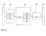
- FIG. 5 shows a block diagram of a coarse structure of the functional modules for damper control according to the invention.
- the individual modules are shown encapsulated for reasons of clarity and clarity. The entire structure is advantageously constructed hierarchically over several levels.
- the functional modules are in a damper controller, preferably the control unit 44 (FIG. FIG. 1 ) integrated.
- the damper control comprises a signal input module 60, an auxiliary function module 62, a regulator module 64, an evaluation module 66 and a signal output module 68.
- the sensor signals of the displacement sensors 30, 32, 34 and 36 and the acceleration sensors 38, 40 and 42 and other Signals available via the CAN bus of the motor vehicle are read in.
- the auxiliary function module 62 includes a man-machine interface module 70, a filter module 72, and a load detection module 74.
- the controller module 64 includes a road detection module 76, an end position damping module 78, a lateral dynamics module 80, a longitudinal dynamics module 82, and a vertical dynamics module 84.
- the evaluation logic module 66 includes a current calculation module 86.
- the regulator modules 76, 78, 80, 82, and 84 advantageously generate a current Size that is proportional to the current.
- the current calculation module 86 the current calculation of all controller output variables to control variables for the dampers 22, 24, 26 and 28 takes place.
- Via the signal output module 68 these control currents are provided to the dampers available.
- both the signal input module 60 and the signal output module 68 can optionally also receive or output further signals, depending on the equipment of the relevant motor vehicle.
- a standard loop is shown. This consists of a distance 90, a controller 92 and a negative feedback of the controlled variable, that is, the actual value on the controller 92.
- the control difference is calculated from the difference between the setpoint (command) and controlled variable.
- the manipulated variable acts on the distance 90 and thus on the controlled variable.
- the disturbance causes a, usually undesirable, change in the controlled variable, which must be compensated.
- the input of the controller 92 is the difference between the measured actual value of the controlled variable and the setpoint.
- the setpoint is also referred to as a reference variable whose value is to be simulated by the measured actual value. Since the actual value can be changed by disturbance variables, the actual value must be tracked to the setpoint.
- the controller 92 determines how the control system responds to the detected deviations, such as fast, sluggish, proportional, integrating or like.
- As output of the Regulator 92 results in a manipulated variable, which affects a controlled system 90.
- the regulation is mainly used to eliminate disturbances in order to correct them.
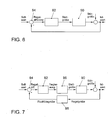
- FIG. 7 is a more detailed representation of the control loop according to FIG. 6 shown.
- An extended control loop with the additional elements actuator 96 and measuring element 98 is shown.
- the adjusting device or the actuator 96 is composed of an electronic component and an electro-hydraulic component.
- the electronic component corresponds to the current regulator in the control unit 44
- the electro-hydraulic component corresponds to the electrically controllable valve of the dampers 22, 24, 26 and 28 respectively. In the following, however, these should not be considered further. These are considered ideal or their influence is neglected.
- the controller output that supplies the control variable agrees with the manipulated variable or is at least proportional to it.
- the controller 92 according to FIG.
- the controller 92 is used to determine a size to respond to a detected by the comparator 94 control difference on the actuator 96.
- the actuator 96 provides the necessary energy in the appropriate physical form to affect the process or the controlled system.
- the measuring element 98 the actual value is measured.
- the disturbance variable may be due to a regulation of the movement of a vehicle body 20 in unevennesses of the road surface, laterally acting forces, such as wind or the like, or similar influences.
- An observer 100 is supplied with a signal wL corresponding to the steering angle set by the driver and the detected vehicle speed vFzg, the observer 100 calculating therefrom the lateral acceleration.
- the output signal of the observer is limited in a limiter 101, since the model of the observer is usually sufficiently accurate only for a limited range of values.
- the output signal aq_vorh of the limiter 101 has a time advantage over a measured lateral acceleration signal aq_mess, since it depends on the steering angle set by the driver on the steering wheel, while the measured acceleration signal depends on the actual steering angle of the wheel later on. Because of the noise inherent in the measured acceleration signal, a filter 102 is provided which clears this signal.
- the two signals aq_vorh and aq are supplied to a corrector 103 which corrects these signals as a function of the driving condition Fahr, the loading condition Bel, the condition of the road Str and the actions of the driver Akt and outputs as corrected output signals aq_vorh * and aq *.
- the signals output from the corrector 103 are supplied to the input of a combiner 104 which appropriately evaluates and combines these input signals and outputs them to a regulator 105 as a combined output signal aq_ges *.
- the controller outputs at its output a designed according to its control curve output signal, this signal should be proportional to the input signal of the downstream actuator.
- the output signal of the regulator is a current i_aq, which is corrected by a corrector 106 due to additional inputs Energ and mode to the output signal i_aq *.
- the input signals according to FIG. 9 are first processed by the regulators 107 and converted into current signals i_aq_vorh and i_aq, which are then processed in a combiner 108 into a combined current signal i_aq_ges.
- the correction in the corrector 106 again corresponds to the correction after FIG. 9 .
- the treatment of input signals in the FIGS. 9 and 10 is essentially equivalent and interchangeable. It is essential that in the combination in the combiner 104 or 108, a meaningful weighting of the input signals is made, which corresponds well to the requirements of the vehicle.
- FIG. 11 is from the output signals according to Figure 82 or input signals corresponding to the FIGS. 9 and 10 formed an output signal which forms the lateral pressure as a result of the lateral acceleration or in other words, the differentiation or derivative of the lateral acceleration signal.
- the two input signals in a combiner 108 become analog FIG. 9 combined and then differentiated in a differentiator 109.
- a filter 110 is provided, which supplies the adjusted and possibly corrected in phase and amplitude input signal at its output to a controller 111.
- the controller 111 outputs for the subsequent actuator a current signal i_daq_ges, which is processed by the differentiation and combination.
- FIG. 12 differs from FIG. 11 essentially in that the two input signals are differentiated separately in differentiators 112 and filtered separately in filters 113 and also regulated separately in controllers 111. Via a combiner 114, the signals are fed to a holding decay function 115.
- the hold fade function 115 ensures that the output does not terminate too early, thus accommodating the inertia of the vehicle's body to be controlled versus the requesting signal.
- the holddown function 115 may also be located after the corrector 106.
- the characters 9 and 10 (Corrector 106) made a correction of the output signal of the Garabklingfunktion 115.
- FIG. 13 will be out FIG. 8 removable signals aq_vorh and aq of an evaluation unit 120 which forms the two input signals to a state signal x_quer, which describes the state of the lateral acceleration of the vehicle and which can take effect in parallel control devices of the vehicle.
- the filter 121 was used to free the signal having a derivative from aq, to possibly change it in phase and to limit its size for the reasons described above.
- the evaluation unit 120 it must be ensured that the two input signals are adequately evaluated and weighted.
- the acceleration signal aq, the derived acceleration signal daq (lateral pressure) and an ESP signal are processed in three separate controllers 116, output as corresponding current output signals from the controllers 116, and then processed in a combiner 117 to an output signal i_quer, the combiner 117 its input signals must be properly weighted and evaluated.
- the output signal of the combiner 117 can serve as a control signal for a downstream actuator.
- FIG. 15 the input signal V Aufbau_ges of a parallel to the regulation of the lateral acceleration operating vertical controller 119 is shown, this input signal can be corrected by a lateral acceleration of the vehicle descriptive state signal x_querdyn via a corrector 118 to a corrected input signal V * philosophical_ges.
- the corrective signal x_querdyn can be determined, for example, by the signal x_quer in accordance with FIG FIG. 13 or another suitable signal.
- the invention thus relates to a method or a control system component for controlling actuators, preferably vehicle shock absorbers, wherein lateral dynamic state variables, such as the transverse acceleration state and the transverse pressure state, are used as control input variables.
Landscapes
- Engineering & Computer Science (AREA)
- Mechanical Engineering (AREA)
- Transportation (AREA)
- Physics & Mathematics (AREA)
- Automation & Control Theory (AREA)
- Mathematical Physics (AREA)
- Chemical & Material Sciences (AREA)
- Combustion & Propulsion (AREA)
- Vehicle Body Suspensions (AREA)
Applications Claiming Priority (1)
| Application Number | Priority Date | Filing Date | Title |
|---|---|---|---|
| DE102007051209A DE102007051209A1 (de) | 2007-10-26 | 2007-10-26 | Verfahren oder Regelungssystemkomponente zur Steuerung von Aktoren vorzugsweise der Dämpfer eines Fahrzeugs über Querdynamikzustandsgrößen |
Publications (3)
| Publication Number | Publication Date |
|---|---|
| EP2052884A2 true EP2052884A2 (fr) | 2009-04-29 |
| EP2052884A3 EP2052884A3 (fr) | 2015-02-11 |
| EP2052884B1 EP2052884B1 (fr) | 2017-10-11 |
Family
ID=40336651
Family Applications (1)
| Application Number | Title | Priority Date | Filing Date |
|---|---|---|---|
| EP08018572.1A Not-in-force EP2052884B1 (fr) | 2007-10-26 | 2008-10-23 | Procédé et système destinés à influencer le mouvement d'une caisse d'un véhicule automobile ou d'un véhicule, pouvant être commandée ou réglée dans ses déroulements de mouvements |
Country Status (2)
| Country | Link |
|---|---|
| EP (1) | EP2052884B1 (fr) |
| DE (1) | DE102007051209A1 (fr) |
Cited By (2)
| Publication number | Priority date | Publication date | Assignee | Title |
|---|---|---|---|---|
| WO2016050425A1 (fr) * | 2014-10-01 | 2016-04-07 | Bayerische Motoren Werke Aktiengesellschaft | Procédé et système pour commander un actionneur d'un système d'amortisseurs actif |
| CN114026006A (zh) * | 2019-08-27 | 2022-02-08 | 宝马股份公司 | 用于车辆的运行辅助方法、控制单元和车辆 |
Families Citing this family (2)
| Publication number | Priority date | Publication date | Assignee | Title |
|---|---|---|---|---|
| CN108382395B (zh) * | 2018-04-03 | 2023-06-27 | 浙江工业大学 | 一种提高公交车乘坐舒适性的智能辅助系统 |
| DE102019213189B4 (de) | 2019-09-02 | 2022-10-06 | Volkswagen Aktiengesellschaft | Aktives Dämpfersystem für ein Kraftfahrzeug |
Citations (3)
| Publication number | Priority date | Publication date | Assignee | Title |
|---|---|---|---|---|
| DE3918735A1 (de) | 1989-06-08 | 1990-12-13 | Bosch Gmbh Robert | Verfahren und vorrichtung zur daempfung von bewegungsablaeufen |
| DE10135020B4 (de) | 2001-07-18 | 2005-03-03 | Robert Bosch Gmbh | Verfahren und Vorrichtung zur Erkennung und Behebung einer Umkippgefahr |
| DE10338994A1 (de) | 2003-08-25 | 2005-03-24 | Trw Fahrwerksysteme Gmbh & Co. Kg | Verfahren zum Betrieb eines Fahrwerkregelsystems und Vorrichtung zur Durchführung des Verfahrens |
Family Cites Families (8)
| Publication number | Priority date | Publication date | Assignee | Title |
|---|---|---|---|---|
| DE4316177B4 (de) * | 1993-05-14 | 2004-07-08 | Zf Sachs Ag | Verfahren zur Einstellung eines stufenlos veränderbaren Schwingungsdämpfers |
| JPH0911723A (ja) * | 1995-06-27 | 1997-01-14 | Nec Eng Ltd | ダンパ可変装置 |
| DE19836674C1 (de) * | 1998-08-13 | 2000-05-25 | Daimler Chrysler Ag | Verfahren zur Beeinflussung des Wankverhaltens von Kraftfahrzeugen |
| DE10215465B9 (de) * | 2002-03-28 | 2017-08-10 | Volkswagen Ag | Verfahren und Vorrichtung zur Regelung der Fahrdynamik |
| EP1518722B1 (fr) * | 2003-09-26 | 2009-05-13 | Aisin Aw Co., Ltd. | Système et procédé de commande d'une suspension de véhicule |
| JP4732061B2 (ja) * | 2004-08-06 | 2011-07-27 | 本田技研工業株式会社 | サスペンションの制御装置 |
| US7715965B2 (en) * | 2004-10-15 | 2010-05-11 | Ford Global Technologies | System and method for qualitatively determining vehicle loading conditions |
| JP4114679B2 (ja) * | 2005-05-24 | 2008-07-09 | トヨタ自動車株式会社 | 車両の減衰力制御装置 |
-
2007
- 2007-10-26 DE DE102007051209A patent/DE102007051209A1/de not_active Withdrawn
-
2008
- 2008-10-23 EP EP08018572.1A patent/EP2052884B1/fr not_active Not-in-force
Patent Citations (3)
| Publication number | Priority date | Publication date | Assignee | Title |
|---|---|---|---|---|
| DE3918735A1 (de) | 1989-06-08 | 1990-12-13 | Bosch Gmbh Robert | Verfahren und vorrichtung zur daempfung von bewegungsablaeufen |
| DE10135020B4 (de) | 2001-07-18 | 2005-03-03 | Robert Bosch Gmbh | Verfahren und Vorrichtung zur Erkennung und Behebung einer Umkippgefahr |
| DE10338994A1 (de) | 2003-08-25 | 2005-03-24 | Trw Fahrwerksysteme Gmbh & Co. Kg | Verfahren zum Betrieb eines Fahrwerkregelsystems und Vorrichtung zur Durchführung des Verfahrens |
Cited By (2)
| Publication number | Priority date | Publication date | Assignee | Title |
|---|---|---|---|---|
| WO2016050425A1 (fr) * | 2014-10-01 | 2016-04-07 | Bayerische Motoren Werke Aktiengesellschaft | Procédé et système pour commander un actionneur d'un système d'amortisseurs actif |
| CN114026006A (zh) * | 2019-08-27 | 2022-02-08 | 宝马股份公司 | 用于车辆的运行辅助方法、控制单元和车辆 |
Also Published As
| Publication number | Publication date |
|---|---|
| EP2052884A3 (fr) | 2015-02-11 |
| DE102007051209A1 (de) | 2009-04-30 |
| EP2052884B1 (fr) | 2017-10-11 |
Similar Documents
| Publication | Publication Date | Title |
|---|---|---|
| DE102007041118B4 (de) | System zur Einstellung von dynamischen und sicherheitsrelevanten Charakteristika eines Fahrzeuges basierend auf der Fahrzeugbelastung | |
| DE102008053008A1 (de) | Verfahren und System zur Beeinflussung der Bewegung eines in seinen Bewegungsabläufen steuerbaren oder regelbaren Fahrzeugaufbaus eines Kraftfahrzeuges und Fahrzeug | |
| EP2205457B1 (fr) | Procédé et système destinés à influencer le mouvement d'une structure de véhicule motorisé pouvant être commandée ou régulée dans ses processus de mouvement et véhicule | |
| EP1197409B1 (fr) | Procédé pour le réglage de la dynamique de marche d'un véhicule automobile | |
| DE4138831C2 (de) | Verfahren und System zum Regeln einer aktiven Aufhängung eines Fahrzeuges | |
| EP0270893B1 (fr) | Dispositif pour le contrôle actif des suspensions de véhicules automobiles | |
| DE10348738B4 (de) | Steuerungssystem für ein Kraftfahrzeug und Verfahren zum Steuern eines Kraftfahrzeugs | |
| EP1722991A1 (fr) | Procede de regulation de la dynamique de roulement d'un vehicule a moteur, dispositif permettant la mise en oeuvre dudit procede et son utilisation | |
| EP2214920B1 (fr) | Procédé et système destinés à influencer le mouvement d'une structure de véhicule motorisé pouvant être commandée ou régulée dans ses processus de mouvement et véhicule | |
| EP2004427A2 (fr) | Système destiné à influencer le comportement routier d'un véhicule automobile | |
| DE102009007357A1 (de) | Verfahren zur Ansteuerung eines aktiven Fahrwerks eines zweiachsigen zweispurigen Kraftfahrzeugs | |
| DE4303160A1 (de) | System zur Regelung und/oder Steuerung eines Kraftfahrzeugfahrwerks | |
| DE102008052991A1 (de) | Verfahren und System zur Beeinflussung der Bewegung eines in seinen Bewegungsabläufen steuerbaren oder regelbaren Fahrzeugaufbaus eines Kraftfahrzeuges und Fahrzeug | |
| EP1536957B1 (fr) | Procede pour commander et regler des amortisseurs a reglage numerique ou analogique | |
| DE102012223984A1 (de) | Verfahren und Vorrichtung zur Beeinflussung der Fahrdynamik eines Kraftfahrzeuges mit einem mittels aktiven Stellgliedern veränderbaren Fahrwerk | |
| EP2052884B1 (fr) | Procédé et système destinés à influencer le mouvement d'une caisse d'un véhicule automobile ou d'un véhicule, pouvant être commandée ou réglée dans ses déroulements de mouvements | |
| WO2007054500A1 (fr) | Procede et dispositif pour stabiliser un vehicule automobile | |
| EP2393678B1 (fr) | Procédé pour commander un mécanisme de roulement actif d'un véhicule à moteur à deux essieux et deux voies | |
| EP2052885B1 (fr) | Procédé et système destinés à influencer le mouvement d'une caisse d'un véhicule automobile ou d'un véhicule, pouvant être commandée ou réglée dans ses déroulements de mouvements | |
| DE102008052993A1 (de) | Verfahren und System zur Beeinflussung der Bewegung eines in seinen Bewegungsabläufen steuerbaren oder regelbaren Fahrzeugaufbaus eines Kraftfahrzeuges und Fahrzeug | |
| EP2052887B1 (fr) | Procédé et système destinés à influencer le mouvement d'une caisse d'un véhicule automobile ou d'un véhicule, pouvant être commandée ou réglée dans ses déroulements de mouvements | |
| EP2052886B1 (fr) | Procédé et système destinés à influencer le mouvement d'une caisse d'un véhicule automobile ou d'un véhicule, pouvant être commandée ou réglée dans ses déroulements de mouvements | |
| DE102008052995A1 (de) | Verfahren und System zur Beeinflussung der Bewegung eines in seinen Bewegungsabläufen steuerbaren oder regelbaren Fahrzeugaufbaus eines Kraftfahrzeuges und Fahrzeug | |
| DE102008052996B4 (de) | Verfahren und System zur Beeinflussung der Bewegung eines in seinen Bewegungsabläufen steuerbaren oder regelbaren Fahrzeugaufbaus eines Kraftfahrzeuges und Fahrzeug | |
| WO2005102745A1 (fr) | Procede pour regler la stabilite de conduite d'un vehicule |
Legal Events
| Date | Code | Title | Description |
|---|---|---|---|
| PUAI | Public reference made under article 153(3) epc to a published international application that has entered the european phase |
Free format text: ORIGINAL CODE: 0009012 |
|
| AK | Designated contracting states |
Kind code of ref document: A2 Designated state(s): AT BE BG CH CY CZ DE DK EE ES FI FR GB GR HR HU IE IS IT LI LT LU LV MC MT NL NO PL PT RO SE SI SK TR |
|
| AX | Request for extension of the european patent |
Extension state: AL BA MK RS |
|
| RAP1 | Party data changed (applicant data changed or rights of an application transferred) |
Owner name: VOLKSWAGEN AKTIENGESELLSCHAFT |
|
| PUAL | Search report despatched |
Free format text: ORIGINAL CODE: 0009013 |
|
| AK | Designated contracting states |
Kind code of ref document: A3 Designated state(s): AT BE BG CH CY CZ DE DK EE ES FI FR GB GR HR HU IE IS IT LI LT LU LV MC MT NL NO PL PT RO SE SI SK TR |
|
| AX | Request for extension of the european patent |
Extension state: AL BA MK RS |
|
| RIC1 | Information provided on ipc code assigned before grant |
Ipc: B60W 40/06 20120101ALN20150105BHEP Ipc: B60G 17/018 20060101ALI20150105BHEP Ipc: B60W 40/10 20120101ALN20150105BHEP Ipc: B60G 17/0165 20060101ALI20150105BHEP Ipc: B60G 17/016 20060101AFI20150105BHEP Ipc: B60G 17/06 20060101ALN20150105BHEP Ipc: B60W 10/22 20060101ALN20150105BHEP |
|
| 17P | Request for examination filed |
Effective date: 20150811 |
|
| RBV | Designated contracting states (corrected) |
Designated state(s): AT BE BG CH CY CZ DE DK EE ES FI FR GB GR HR HU IE IS IT LI LT LU LV MC MT NL NO PL PT RO SE SI SK TR |
|
| AKX | Designation fees paid |
Designated state(s): AT BE BG CH CY CZ DE DK EE ES FI FR GB GR HR HU IE IS IT LI LT LU LV MC MT NL NO PL PT RO SE SI SK TR |
|
| AXX | Extension fees paid |
Extension state: BA Extension state: RS Extension state: AL Extension state: MK |
|
| RIC1 | Information provided on ipc code assigned before grant |
Ipc: B60W 10/22 20060101ALN20170502BHEP Ipc: B60G 17/0165 20060101ALI20170502BHEP Ipc: B60G 17/016 20060101AFI20170502BHEP Ipc: B60G 17/018 20060101ALI20170502BHEP Ipc: B60W 40/10 20120101ALN20170502BHEP Ipc: B60W 40/06 20120101ALN20170502BHEP Ipc: B60G 17/06 20060101ALN20170502BHEP |
|
| GRAJ | Information related to disapproval of communication of intention to grant by the applicant or resumption of examination proceedings by the epo deleted |
Free format text: ORIGINAL CODE: EPIDOSDIGR1 |
|
| STAA | Information on the status of an ep patent application or granted ep patent |
Free format text: STATUS: GRANT OF PATENT IS INTENDED |
|
| GRAP | Despatch of communication of intention to grant a patent |
Free format text: ORIGINAL CODE: EPIDOSNIGR1 |
|
| INTG | Intention to grant announced |
Effective date: 20170711 |
|
| GRAS | Grant fee paid |
Free format text: ORIGINAL CODE: EPIDOSNIGR3 |
|
| GRAA | (expected) grant |
Free format text: ORIGINAL CODE: 0009210 |
|
| STAA | Information on the status of an ep patent application or granted ep patent |
Free format text: STATUS: THE PATENT HAS BEEN GRANTED |
|
| AK | Designated contracting states |
Kind code of ref document: B1 Designated state(s): AT BE BG CH CY CZ DE DK EE ES FI FR GB GR HR HU IE IS IT LI LT LU LV MC MT NL NO PL PT RO SE SI SK TR |
|
| REG | Reference to a national code |
Ref country code: GB Ref legal event code: FG4D Free format text: NOT ENGLISH |
|
| REG | Reference to a national code |
Ref country code: CH Ref legal event code: EP |
|
| REG | Reference to a national code |
Ref country code: FR Ref legal event code: PLFP Year of fee payment: 10 |
|
| REG | Reference to a national code |
Ref country code: IE Ref legal event code: FG4D Free format text: LANGUAGE OF EP DOCUMENT: GERMAN |
|
| REG | Reference to a national code |
Ref country code: AT Ref legal event code: REF Ref document number: 935679 Country of ref document: AT Kind code of ref document: T Effective date: 20171115 |
|
| REG | Reference to a national code |
Ref country code: DE Ref legal event code: R096 Ref document number: 502008015665 Country of ref document: DE |
|
| REG | Reference to a national code |
Ref country code: NL Ref legal event code: MP Effective date: 20171011 |
|
| REG | Reference to a national code |
Ref country code: LT Ref legal event code: MG4D |
|
| PG25 | Lapsed in a contracting state [announced via postgrant information from national office to epo] |
Ref country code: NL Free format text: LAPSE BECAUSE OF FAILURE TO SUBMIT A TRANSLATION OF THE DESCRIPTION OR TO PAY THE FEE WITHIN THE PRESCRIBED TIME-LIMIT Effective date: 20171011 |
|
| PG25 | Lapsed in a contracting state [announced via postgrant information from national office to epo] |
Ref country code: NO Free format text: LAPSE BECAUSE OF FAILURE TO SUBMIT A TRANSLATION OF THE DESCRIPTION OR TO PAY THE FEE WITHIN THE PRESCRIBED TIME-LIMIT Effective date: 20180111 Ref country code: ES Free format text: LAPSE BECAUSE OF FAILURE TO SUBMIT A TRANSLATION OF THE DESCRIPTION OR TO PAY THE FEE WITHIN THE PRESCRIBED TIME-LIMIT Effective date: 20171011 Ref country code: FI Free format text: LAPSE BECAUSE OF FAILURE TO SUBMIT A TRANSLATION OF THE DESCRIPTION OR TO PAY THE FEE WITHIN THE PRESCRIBED TIME-LIMIT Effective date: 20171011 Ref country code: SE Free format text: LAPSE BECAUSE OF FAILURE TO SUBMIT A TRANSLATION OF THE DESCRIPTION OR TO PAY THE FEE WITHIN THE PRESCRIBED TIME-LIMIT Effective date: 20171011 Ref country code: LT Free format text: LAPSE BECAUSE OF FAILURE TO SUBMIT A TRANSLATION OF THE DESCRIPTION OR TO PAY THE FEE WITHIN THE PRESCRIBED TIME-LIMIT Effective date: 20171011 |
|
| PG25 | Lapsed in a contracting state [announced via postgrant information from national office to epo] |
Ref country code: HR Free format text: LAPSE BECAUSE OF FAILURE TO SUBMIT A TRANSLATION OF THE DESCRIPTION OR TO PAY THE FEE WITHIN THE PRESCRIBED TIME-LIMIT Effective date: 20171011 Ref country code: LV Free format text: LAPSE BECAUSE OF FAILURE TO SUBMIT A TRANSLATION OF THE DESCRIPTION OR TO PAY THE FEE WITHIN THE PRESCRIBED TIME-LIMIT Effective date: 20171011 Ref country code: BG Free format text: LAPSE BECAUSE OF FAILURE TO SUBMIT A TRANSLATION OF THE DESCRIPTION OR TO PAY THE FEE WITHIN THE PRESCRIBED TIME-LIMIT Effective date: 20180111 Ref country code: IS Free format text: LAPSE BECAUSE OF FAILURE TO SUBMIT A TRANSLATION OF THE DESCRIPTION OR TO PAY THE FEE WITHIN THE PRESCRIBED TIME-LIMIT Effective date: 20180211 Ref country code: GR Free format text: LAPSE BECAUSE OF FAILURE TO SUBMIT A TRANSLATION OF THE DESCRIPTION OR TO PAY THE FEE WITHIN THE PRESCRIBED TIME-LIMIT Effective date: 20180112 |
|
| REG | Reference to a national code |
Ref country code: CH Ref legal event code: PL |
|
| REG | Reference to a national code |
Ref country code: DE Ref legal event code: R097 Ref document number: 502008015665 Country of ref document: DE |
|
| REG | Reference to a national code |
Ref country code: IE Ref legal event code: MM4A |
|
| PG25 | Lapsed in a contracting state [announced via postgrant information from national office to epo] |
Ref country code: CZ Free format text: LAPSE BECAUSE OF FAILURE TO SUBMIT A TRANSLATION OF THE DESCRIPTION OR TO PAY THE FEE WITHIN THE PRESCRIBED TIME-LIMIT Effective date: 20171011 Ref country code: LU Free format text: LAPSE BECAUSE OF NON-PAYMENT OF DUE FEES Effective date: 20171023 Ref country code: EE Free format text: LAPSE BECAUSE OF FAILURE TO SUBMIT A TRANSLATION OF THE DESCRIPTION OR TO PAY THE FEE WITHIN THE PRESCRIBED TIME-LIMIT Effective date: 20171011 Ref country code: CH Free format text: LAPSE BECAUSE OF NON-PAYMENT OF DUE FEES Effective date: 20171031 Ref country code: DK Free format text: LAPSE BECAUSE OF FAILURE TO SUBMIT A TRANSLATION OF THE DESCRIPTION OR TO PAY THE FEE WITHIN THE PRESCRIBED TIME-LIMIT Effective date: 20171011 Ref country code: LI Free format text: LAPSE BECAUSE OF NON-PAYMENT OF DUE FEES Effective date: 20171031 Ref country code: SK Free format text: LAPSE BECAUSE OF FAILURE TO SUBMIT A TRANSLATION OF THE DESCRIPTION OR TO PAY THE FEE WITHIN THE PRESCRIBED TIME-LIMIT Effective date: 20171011 Ref country code: MC Free format text: LAPSE BECAUSE OF FAILURE TO SUBMIT A TRANSLATION OF THE DESCRIPTION OR TO PAY THE FEE WITHIN THE PRESCRIBED TIME-LIMIT Effective date: 20171011 |
|
| PLBE | No opposition filed within time limit |
Free format text: ORIGINAL CODE: 0009261 |
|
| STAA | Information on the status of an ep patent application or granted ep patent |
Free format text: STATUS: NO OPPOSITION FILED WITHIN TIME LIMIT |
|
| REG | Reference to a national code |
Ref country code: BE Ref legal event code: MM Effective date: 20171031 |
|
| PG25 | Lapsed in a contracting state [announced via postgrant information from national office to epo] |
Ref country code: BE Free format text: LAPSE BECAUSE OF NON-PAYMENT OF DUE FEES Effective date: 20171031 Ref country code: RO Free format text: LAPSE BECAUSE OF FAILURE TO SUBMIT A TRANSLATION OF THE DESCRIPTION OR TO PAY THE FEE WITHIN THE PRESCRIBED TIME-LIMIT Effective date: 20171011 Ref country code: IT Free format text: LAPSE BECAUSE OF FAILURE TO SUBMIT A TRANSLATION OF THE DESCRIPTION OR TO PAY THE FEE WITHIN THE PRESCRIBED TIME-LIMIT Effective date: 20171011 Ref country code: PL Free format text: LAPSE BECAUSE OF FAILURE TO SUBMIT A TRANSLATION OF THE DESCRIPTION OR TO PAY THE FEE WITHIN THE PRESCRIBED TIME-LIMIT Effective date: 20171011 |
|
| 26N | No opposition filed |
Effective date: 20180712 |
|
| PG25 | Lapsed in a contracting state [announced via postgrant information from national office to epo] |
Ref country code: MT Free format text: LAPSE BECAUSE OF FAILURE TO SUBMIT A TRANSLATION OF THE DESCRIPTION OR TO PAY THE FEE WITHIN THE PRESCRIBED TIME-LIMIT Effective date: 20171011 |
|
| REG | Reference to a national code |
Ref country code: FR Ref legal event code: PLFP Year of fee payment: 11 |
|
| PG25 | Lapsed in a contracting state [announced via postgrant information from national office to epo] |
Ref country code: IE Free format text: LAPSE BECAUSE OF NON-PAYMENT OF DUE FEES Effective date: 20171023 |
|
| PG25 | Lapsed in a contracting state [announced via postgrant information from national office to epo] |
Ref country code: SI Free format text: LAPSE BECAUSE OF FAILURE TO SUBMIT A TRANSLATION OF THE DESCRIPTION OR TO PAY THE FEE WITHIN THE PRESCRIBED TIME-LIMIT Effective date: 20171011 |
|
| REG | Reference to a national code |
Ref country code: AT Ref legal event code: MM01 Ref document number: 935679 Country of ref document: AT Kind code of ref document: T Effective date: 20171023 |
|
| PG25 | Lapsed in a contracting state [announced via postgrant information from national office to epo] |
Ref country code: AT Free format text: LAPSE BECAUSE OF NON-PAYMENT OF DUE FEES Effective date: 20171023 |
|
| PG25 | Lapsed in a contracting state [announced via postgrant information from national office to epo] |
Ref country code: HU Free format text: LAPSE BECAUSE OF FAILURE TO SUBMIT A TRANSLATION OF THE DESCRIPTION OR TO PAY THE FEE WITHIN THE PRESCRIBED TIME-LIMIT; INVALID AB INITIO Effective date: 20081023 |
|
| PG25 | Lapsed in a contracting state [announced via postgrant information from national office to epo] |
Ref country code: CY Free format text: LAPSE BECAUSE OF NON-PAYMENT OF DUE FEES Effective date: 20171011 |
|
| PG25 | Lapsed in a contracting state [announced via postgrant information from national office to epo] |
Ref country code: TR Free format text: LAPSE BECAUSE OF FAILURE TO SUBMIT A TRANSLATION OF THE DESCRIPTION OR TO PAY THE FEE WITHIN THE PRESCRIBED TIME-LIMIT Effective date: 20171011 |
|
| PG25 | Lapsed in a contracting state [announced via postgrant information from national office to epo] |
Ref country code: PT Free format text: LAPSE BECAUSE OF FAILURE TO SUBMIT A TRANSLATION OF THE DESCRIPTION OR TO PAY THE FEE WITHIN THE PRESCRIBED TIME-LIMIT Effective date: 20171011 |
|
| PGFP | Annual fee paid to national office [announced via postgrant information from national office to epo] |
Ref country code: FR Payment date: 20221024 Year of fee payment: 15 |
|
| PGFP | Annual fee paid to national office [announced via postgrant information from national office to epo] |
Ref country code: GB Payment date: 20221018 Year of fee payment: 15 Ref country code: DE Payment date: 20221031 Year of fee payment: 15 |
|
| P01 | Opt-out of the competence of the unified patent court (upc) registered |
Effective date: 20230523 |
|
| REG | Reference to a national code |
Ref country code: DE Ref legal event code: R119 Ref document number: 502008015665 Country of ref document: DE |
|
| GBPC | Gb: european patent ceased through non-payment of renewal fee |
Effective date: 20231023 |
|
| PG25 | Lapsed in a contracting state [announced via postgrant information from national office to epo] |
Ref country code: GB Free format text: LAPSE BECAUSE OF NON-PAYMENT OF DUE FEES Effective date: 20231023 |
|
| PG25 | Lapsed in a contracting state [announced via postgrant information from national office to epo] |
Ref country code: GB Free format text: LAPSE BECAUSE OF NON-PAYMENT OF DUE FEES Effective date: 20231023 Ref country code: FR Free format text: LAPSE BECAUSE OF NON-PAYMENT OF DUE FEES Effective date: 20231031 Ref country code: DE Free format text: LAPSE BECAUSE OF NON-PAYMENT OF DUE FEES Effective date: 20240501 |