EP2052807B1 - Poste de travail de montage - Google Patents
Poste de travail de montage Download PDFInfo
- Publication number
- EP2052807B1 EP2052807B1 EP07119238A EP07119238A EP2052807B1 EP 2052807 B1 EP2052807 B1 EP 2052807B1 EP 07119238 A EP07119238 A EP 07119238A EP 07119238 A EP07119238 A EP 07119238A EP 2052807 B1 EP2052807 B1 EP 2052807B1
- Authority
- EP
- European Patent Office
- Prior art keywords
- assembly
- station according
- database
- stored
- assembly station
- Prior art date
- Legal status (The legal status is an assumption and is not a legal conclusion. Google has not performed a legal analysis and makes no representation as to the accuracy of the status listed.)
- Active
Links
- 239000000463 material Substances 0.000 claims description 41
- 238000000034 method Methods 0.000 claims description 14
- 230000008569 process Effects 0.000 claims description 13
- 238000012360 testing method Methods 0.000 claims description 10
- 238000010923 batch production Methods 0.000 claims description 3
- 238000001514 detection method Methods 0.000 claims description 2
- 238000012800 visualization Methods 0.000 abstract description 4
- 238000004519 manufacturing process Methods 0.000 description 11
- 238000009434 installation Methods 0.000 description 8
- 238000002360 preparation method Methods 0.000 description 5
- 240000006829 Ficus sundaica Species 0.000 description 4
- 238000010586 diagram Methods 0.000 description 4
- 230000005540 biological transmission Effects 0.000 description 3
- 230000008901 benefit Effects 0.000 description 2
- 230000008859 change Effects 0.000 description 2
- 238000012805 post-processing Methods 0.000 description 2
- 238000012545 processing Methods 0.000 description 2
- 238000012549 training Methods 0.000 description 2
- 230000001960 triggered effect Effects 0.000 description 2
- 230000002950 deficient Effects 0.000 description 1
- 238000013461 design Methods 0.000 description 1
- 230000006870 function Effects 0.000 description 1
- 239000003292 glue Substances 0.000 description 1
- 230000006872 improvement Effects 0.000 description 1
- 238000007726 management method Methods 0.000 description 1
- 238000012544 monitoring process Methods 0.000 description 1
- 230000002688 persistence Effects 0.000 description 1
- 238000003825 pressing Methods 0.000 description 1
- 238000001454 recorded image Methods 0.000 description 1
- 238000013024 troubleshooting Methods 0.000 description 1
Images

Classifications
-
- B—PERFORMING OPERATIONS; TRANSPORTING
- B23—MACHINE TOOLS; METAL-WORKING NOT OTHERWISE PROVIDED FOR
- B23P—METAL-WORKING NOT OTHERWISE PROVIDED FOR; COMBINED OPERATIONS; UNIVERSAL MACHINE TOOLS
- B23P21/00—Machines for assembling a multiplicity of different parts to compose units, with or without preceding or subsequent working of such parts, e.g. with programme control
- B23P21/002—Machines for assembling a multiplicity of different parts to compose units, with or without preceding or subsequent working of such parts, e.g. with programme control the units stationary whilst being composed
-
- G—PHYSICS
- G05—CONTROLLING; REGULATING
- G05B—CONTROL OR REGULATING SYSTEMS IN GENERAL; FUNCTIONAL ELEMENTS OF SUCH SYSTEMS; MONITORING OR TESTING ARRANGEMENTS FOR SUCH SYSTEMS OR ELEMENTS
- G05B19/00—Programme-control systems
- G05B19/02—Programme-control systems electric
- G05B19/04—Programme control other than numerical control, i.e. in sequence controllers or logic controllers
- G05B19/042—Programme control other than numerical control, i.e. in sequence controllers or logic controllers using digital processors
-
- G—PHYSICS
- G05—CONTROLLING; REGULATING
- G05B—CONTROL OR REGULATING SYSTEMS IN GENERAL; FUNCTIONAL ELEMENTS OF SUCH SYSTEMS; MONITORING OR TESTING ARRANGEMENTS FOR SUCH SYSTEMS OR ELEMENTS
- G05B2219/00—Program-control systems
- G05B2219/30—Nc systems
- G05B2219/31—From computer integrated manufacturing till monitoring
- G05B2219/31027—Computer assisted manual assembly CAA, display operation, tool, result
-
- Y—GENERAL TAGGING OF NEW TECHNOLOGICAL DEVELOPMENTS; GENERAL TAGGING OF CROSS-SECTIONAL TECHNOLOGIES SPANNING OVER SEVERAL SECTIONS OF THE IPC; TECHNICAL SUBJECTS COVERED BY FORMER USPC CROSS-REFERENCE ART COLLECTIONS [XRACs] AND DIGESTS
- Y02—TECHNOLOGIES OR APPLICATIONS FOR MITIGATION OR ADAPTATION AGAINST CLIMATE CHANGE
- Y02P—CLIMATE CHANGE MITIGATION TECHNOLOGIES IN THE PRODUCTION OR PROCESSING OF GOODS
- Y02P90/00—Enabling technologies with a potential contribution to greenhouse gas [GHG] emissions mitigation
- Y02P90/02—Total factory control, e.g. smart factories, flexible manufacturing systems [FMS] or integrated manufacturing systems [IMS]
Definitions
- the invention relates to an assembly workstation according to the preamble of claim 1.
- Such an assembly workstation is from the WO 2007/044558 known.
- High-volume assembly is a highly efficient process today. This means that short assembly times are achieved and a high quality is reproducible. Assembly in mass production is already fully automated in many areas. In most cases, industrial robots are used, which are programmed in different ways and execute the corresponding assembly step independently. Depending on the devices to be mounted, however, semi-automatic mounting is also possible. Here, workers are assigned to a production line, with each worker always performing the same assembly step. Due to the high number of pieces, mass production pays for a longer learning phase, in which the respective worker is intensively trained in the assembly step to be performed by him. This leads - similar to the fully automatic assembly - to a short assembly time and a high reproducibility.
- the invention has for its object to design a mounting station for small batch production according to the preamble of claim 1 so that a comparable with the mass production quality, assembly time and reproducibility can be achieved.
- an assembly workstation for small batch production with the features of claim 1.
- the mounting control a display for visualization of each upcoming assembly step and a database for storing the visualization data in connection. Since each assembly step is shown on the display, a worker without training phase can begin immediately with the assembly. As the number of assembly operations increases, the worker will learn the assembly steps better and the time required for the assembly steps will be shortened accordingly. Since the worker can pick up suggestions from the display every time, even after a large number of already completed assembly processes, the quality and reproducibility of the assembly increases.
- Means are provided at the assembly workstation, which end an assembly step and advance to the next assembly step or end the assembly process. In this way, always exactly the mounting step is shown on the display, which is currently being performed. After the last assembly step, the entire assembly process is completed.
- the means have an operating element.
- This operating element is manually operated by the worker at the assembly workstation as soon as he has completed an assembly step. Depending on the installation step, the next step in the assembly is then shown on the display, or the assembly process is terminated.
- the means independently determine the completion of the assembly step. In this way, the worker is deprived of the responsibility to determine the completion of the assembly process itself. If the means work with the appropriate accuracy, the quality of the installation no longer depends on the current condition of the worker. The reproducibility can be increased so enormous.
- signals are transmitted from the mounting controller to the tool.
- parameters are advantageously stored for each assembly step. These parameters relate to variables that must be achieved at the respective assembly step.
- the tool has corresponding sensors that can record these sizes.
- the transmitted size is compared by the mounting control with the respectively deposited parameter.
- a test device is provided which checks the achievement of the stored parameters. This test device can be part of the mounting control.
- a stop signal is sent to the tool as soon as the size transmitted by the tool matches the parameter stored in the database. Subsequently, the mounting control determines the completion of the assembling step. Also in the database, after the stored parameters have been reached, the associated assembly step is registered as completed.
- This data set contains the measured mounting parameter (s).
- a programmable screwdriver with limit value detection is used as a tool.
- the test equipment, the achievement the stored parameter checked be integrated into the screwdriver.
- the nutrunner detects the current torque and switches off at the torque transmitted by the assembly control.
- the screwdriver generates a stop signal, which is sent to the assembly control. This then registers the assembly step as finished and proceeds to the next assembly step.
- the termination of the assembly step can also be determined differently.
- This also applies to assembly steps where no tool is used.
- a camera is provided for such cases. This camera records images of the assembly step during assembly and compares these images with data stored in the database for this assembly step. As soon as the stored data matches the data supplied by the camera, the installation step is considered to be completed successfully. In this way, the mounting control via the camera determines the completion of the mounting step. Also during assembly steps with tools that allow a data acquisition, the camera monitoring can be useful because it means additional security for the achievement of the assembly step target.
- the mounting control is also used for the provision of the material required for the assembly. Since not only an assembly operation is to be carried out with the assembly workstation, the different assembly operations must be distinguishable from each other. It is therefore assigned each commissioning operation in conjunction with the number of units to be mounted a commission number and stored in the database.
- a material cart is provided for the assembly workstation, which is marked with the respective commission number.
- This material cart is equipped with the material which is required for the processing of a commission number assigned to the assembly. The worker has the exact number of parts needed on site for this assembly. This provides additional security, as the absence or persistence of a part indicates an assembly error.
- a machine-readable code or an RFID chip is advantageously used to identify the material cart instead of a hand-to-fill tab.
- a machine-readable code for example, represents a barcode that can be read with a barcode scanner. Even more advantageous is the use of an RFID chip.
- both the writing and the reading of the marking can be done automatically and without contact.
- the assembly workstation can not only be used for highly efficient assembly, but it also allows the assembly instructions to be created at the same time.
- a camera is provided, at least temporarily, with which images and / or video sequences for visualizing the individual assembly steps are recorded.
- This camera is connected to the mounting controller so that the recorded images and / or video sequences can be immediately stored in the database for the mounting step.
- the image format of the camera is advantageously set exactly to the resolution of the display. This allows you to optimize the ratio between file size and the best possible representation. Also, such an additional post-processing with the Camera recorded data avoided.
- the images and video sequences are thus assigned directly to the individual assembly steps and stored accordingly in the database. A reworking of the assembly instructions is unnecessary.
- Some devices need to be mounted on different assembly workstations, as they require special tools and equipment that can not be accommodated at an assembly workstation. It also happens that after a mounting step, for example, after mounting an electrical assembly, the function of the built-in electrical component must be tested only at a special test site. Only after this test, the device can be mounted on the assembly workstation.
- a mobile mounting base plate is provided. The device is arranged on this mobile mounting base plate and can thus be transported from the assembly workstation to the testing device and back again.
- the mobile mounting base plate is arranged on a mobile frame.
- the mobile mounting base plate is brought from a conveyor belt to different stations.
- connection base 8 which is fixedly mounted and converge on the all electrical connections and all data cables.
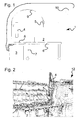
- connection base 8 At the connection base 8 and the screen 4 is attached. This can be firmly mounted (s. Fig. 2 ), but also, as in Fig. 1 shown to be designed as a standalone unit.
- connection base 8 includes the mounting controller 3, which is integrated here in a standard personal computer (PC).
- PC personal computer
- the data cable of a screwdriver 5 the screen 4 and possibly a camera 10 are connected.
- a connection via cable is shown, but of course, a wireless connection, for example via WLAN possible.
- connection base 8 has a tool boom 9 with cables for the electrical connection of the screwdriver 5 and for the data transmission between the screwdriver 5 and the mounting controller 3.
- the camera 10 is in the described embodiment, only necessary for the preparation of the mounting instruction and is therefore not fixed Installed. To prepare the assembly instructions, the camera 10 is mounted on a tripod so that the viewing angle of the camera corresponds approximately to the viewing angle of a worker who looks at the mounting on the devices 2 during assembly. In this way, it is ensured that the same detail of the device 2 is displayed on the screen 4, which sees the assembling workers in front of him.
- connection base 8 not fixedly connected to the connection base 8 is the mounting base plate 6. This rests on a mobile table frame 7. The devices 2 on the mounting base plate 6 can be easily brought to other assembly workstations or to a test station.
- the mounting base plate 6 has for this purpose four mounting positions for up to four devices. By assembling four devices at the same time, the worker 11 can perform the same assembly step four times in succession. This saves a lot of time and increases reliability.
- Fig. 2 is also a material cart 12 can be seen. On this material cart, all material needed for the assembly of the four devices 2 is assembled.
- Small series usually include a number of units of 100-1000 pieces per year. This total lot size is then split into 50-100-piece release orders distributed throughout the year, depending on product value.
- the mounting work according to the invention is provided for such order sizes.
- the parts lists 14 are assigned to a device and are divided in the preparation of the list of materials 16 on the assembly steps. Even when creating the material lists, the mounting control 3 can be included. So it is z. B. possible in a bolting to be performed the appropriate parameters, such as strength of the screw, depth of the threaded hole, etc. to enter in a table.
- the mounting control takes the table from the appropriate screw and the associated mounting parameters such as tightening torque, rotation angle or number of revolutions, speed, and type or size of the tool blade or the tool insert. The tolerance range for these parameters can also be found in the table. Both the screw found, as well as the mounting parameters are assigned to the corresponding assembly step and stored.
- the data for the visualization of the assembly step are generated by the camera 10, in particular a digital camera.
- This camera 10 is directly connected to the mounting controller 3 via cable or wireless data transmission.
- the image format and the resolution of the camera 10 are exactly matched to the image format and the resolution of the screen 4.
- space is handled economically and you still achieve the best possible representation.
- a post-processing of the image data 17 thus generated is unnecessary.
- the image can be viewed immediately on the screen 4. If the picture does not meet the expectations, the picture can be repeated and the first picture is overwritten.
- the image is found to be good, it is transferred to the database at the touch of a button and stored in the assembly step.
- a note text can be entered.
- the hint text is displayed together with the image on the screen 4 so that the image information is not superimposed and remains visible.
- a video sequence can be installed.
- the video sequence is recorded in the same way as the pictures are taken.
- the video sequence is also stored in the database in relation to the corresponding assembly step. In a short time a clear and process-safe assembly instructions are created in this way.
- Each assembly step is assigned at least the data record with the image or video data 17.
- the mounting step refers to a record with the material to be mounted. Some assembly steps, however, are still more records, such. B. associated records with the mounting parameters.
- the assembly steps which are performed without tools or with a non-programmable tool, for example with a glue gun, have no record with mounting parameters. All assembly steps together are stored in the database and together form the assembly instructions 15. The assembly instructions 15 referenced again to a device and a commission number.
- the material list 16 thus contains the material in the order in which it is needed during the assembly.
- the assembly control 3 In order to prepare the assembly instructions 15, the assembly control 3 consequently requires the data on the article 13, that is, the data on the size of the entire series, the size of a call order, appointments to be met, etc.
- the parts list 14 is also transmitted to the assembly control 3.
- the image data 17 are then input to the individual assembly steps.
- the mounting control 3 stores in the database assembly instructions 15 and the list of materials 16.
- the material needed for the assembly 19 (s. Fig. 4 ) assembled in a mobile material cart 12.
- the material 19 required for the assembly is provided only in the quantity of the current release order.
- the material cart 12 is re-equipped.
- a machine-readable barcode label with the commission number of the assembly process is attached to the material cart 12.
- the composition of the required material for mounting 19 in the material carriage 12 can be done again by the mounting controller 3. She uses the order data 18, which she accesses via the commission number. Furthermore, she refers back to the previously prepared list of materials 16. Under certain circumstances, even an automatic removal of stored goods 22 is possible. If this is not the case, the material cart 12 is equipped by hand.
- the material cart 12 is usually brought laterally to the assembly workstation 1.
- a bar code scanner not shown here, which is also in connection with the mounting control 3
- the commission number of the assembly process is recorded. This commission number will load the correct installation instructions 16 and the associated additional information from the database.
- the additional information is provided via the production control and includes the order data 18.
- the order data 18 includes the total number of the call order and the number of devices to be mounted in parallel at the same time, ie the number of assembly stations to be used on the mounting base plate 6.
- the number of too used assembly sites is specified by the production management in the context of work preparation and depends on the geometry of the device and the size of the mounting base plate 6. The number is typically between 3 and 10 and is at most as large as the call order to be mounted.
- the assembly begins with the worker 11 first entering his personnel number or scanning it from his company card with the barcode scanner. Thereafter, the base plates or chassis - corresponding to the number of assembly sites to be used - designed on the mounting base plate 6.
- the assembly sites to be used are displayed as individual boxes at the bottom of the screen 4.
- the worker 11 is displayed to check on which devices the current assembly step has already been performed.
- the assigned boxes are marked accordingly.
- the worker 11 is then instructed via the screen 4 to apply bar code labels with a unique serial device identification number to the chassis according to the position shown in the first image. Then the barcode scanner scans each of the numbers starting from the left. Successfully reading the number will advance to the next device and the corresponding box at the bottom of screen 4 will be highlighted accordingly.
- the mounting controller 3 automatically switches to the first mounting step.
- new data records are created in the background, whose reference is the device identification number just entered as the chassis ID.
- All device-specific data 21 are now recorded for these data records, which are also assigned the personnel number of the worker 11.
- the most recently performed assembly step is recorded with all mounting parameters.
- the assembly instructions in the form of images or video sequences in the previously defined sequence of assembly steps on the screen 4 in the central view position of the worker 11 at the assembly workstation 1 is shown.
- the worker 11 determines even when an assembly step is completed on a device and transmits this decision of the mounting controller 3 by pressing a button.
- the mounting control 3 repeats each assembly step exactly as often as devices are mounted in parallel.
- an assembly step is explained in which the programmable screwdriver 5 is to be used.
- the screwdriver 5 is programmed by the mounting control 5 with the mounting parameters stored in the database for this assembly step and is immediately ready for the corresponding screw connection.
- the worker 11 takes the material cart 12, the parts to be fastened and sets them as indicated on the screen 4 on the chassis. After the completion of this mounting step, he presses a button, not shown, to indicate to the mounting controller 3 that this assembling step is finished.
- the mounting control 3 gives the worker 11 in the in Fig. 2 shown example four times the same picture before and marked according to the progress of installation, the boxes at the bottom of the screen 4. Is also placed on the fourth device, the part to be fastened and pressed the button, the mounting controller 3 switches to the next assembly step.
- the image shown on the screen 4 for the next assembly step shows the screwdriver 5 with a detected screw at the place of use.
- the worker 11 takes from a marked with the number of the assembly step box on the material carriage 12, the corresponding screw and puts them in the screwdriver 5 a.
- standard screws could also be accommodated in a box at the assembly workstation 1 for several assembly steps.
- the boxes with the standard screws are equipped with LEDs, for example. If one of these standard screws is required in an assembly step, the mounting control 3 activates the LED on the corresponding box.
- the worker 11 knows in this way, from which box he must remove the screw required for the assembly step.
- the screwdriver 5 is now brought with the screw on the screwing and triggered by push start.
- the bolting operation is performed and the measured mounting data is stored in the database with reference to the mounting step and the chassis ID.
- the working time required for the assembly step is stored in the database.
- the system advances to the next device. After performing this mounting step on the last device, the mounting controller 3 switches to the next mounting step.
- Fig. 3 the assembly 20 is greatly simplified as a diagram. Since material 19 in the material carriage 12 of the assembly 20 is supplied. At the same time, the assembly instructions 15 and the order data 18 are used during assembly. Finally, during assembly 20, the device 2 is produced. For this purpose, device-specific data 21 are generated during the assembly 20, which data may later be helpful in particular in troubleshooting.
- the assembly can be interrupted or canceled at any time. This is important if e.g. electrical tests must be carried out at other test stations or other equipment must be brought forward. In these cases, the installation of all devices is interrupted on the mounting base plate 6 and replaced the entire mounting base plate 6 together with the mobile table frame 7. If you change to another commission number, the material cart 12 will also be replaced.
- the installation of partially assembled devices is continued by reading the Chasis ID with the barcode scanner.
- the mounting control 3 automatically switches to the correct commission number, the correct assembly instructions and the correct assembly step.
- interrupted work can be easily continued. This is possible because the data structures are created accordingly.
Claims (19)
- Poste de montage (1) pour une fabrication en petites séries afin d'exécuter un processus de montage avec au moins une étape de montage, qui est reliée à une commande de montage (3), avec au moins un outil (5), dans lequel un écran (4) destiné à visualiser l'étape de montage en attente et une banque de données destinée à enregistrer les données de visualisation (17) sont en lien avec la commande de montage (3), dans lequel des moyens sont prévus qui constatent de façon autonome la fin de l'étape de montage et avancent à l'étape de montage suivante ou mettent fin au processus de montage, caractérisé en ce qu'après la fin d'une étape de montage à cette étape de montage un ensemble de données (21) est placé dans la banque de données, alors qu'au moins une information est transmise à l'ouvrier monteur ainsi qu'une référence à un numéro d'identification d'appareil.
- Poste de montage selon la revendication 1, caractérisé en ce que pour la visualisation des images et/ou des séquences vidéo concernant les étapes de montage sont représentées sur l'écran (4).
- Poste de montage selon la revendication 2, caractérisé en ce que des moyens sont prévus qui mettent fin à une étape de montage.
- Poste de montage selon la revendication 3, caractérisé en ce que les moyens présentent un élément d'utilisation.
- Poste de montage selon la revendication 4, caractérisé en ce que l'outil (5) est en lien avec la commande de montage (3) et est transmis à ces données.
- Poste de montage selon la revendication 5, caractérisé en ce que des paramètres sont enregistrés dans la banque de données à chaque étape de montage et des signaux sont transmis de la commande de montage (3) à l'outil (5).
- Poste de montage selon la revendication 6, caractérisé en ce qu'un dispositif d'essai est prévu qui vérifie l'obtention des paramètres enregistrés.
- Poste de montage selon la revendication 7, caractérisé en ce qu'après l'obtention des paramètres enregistrés, l'étape de montage correspondante est enregistrée comme terminée.
- Poste de montage selon la revendication 8, caractérisé en ce qu'une machine à visser programmable (5) avec détection des valeurs limites est utilisée comme outil.
- Poste de montage selon la revendication 1, caractérisé en ce qu'un appareil photographique (10) est prévu.
- Poste de montage selon la revendication 10, caractérisé en ce que la commande de montage (3) constate au moyen de l'appareil photographique (10) la fin d'une étape de montage.
- Poste de montage selon la revendication 2, caractérisé en ce que pour chaque processus de montage un numéro de commission est placé dans la banque de données.
- Poste de montage selon la revendication 12, caractérisé en ce que dans la banque de données est placé un matériau nécessaire à chaque étape de montage.
- Poste de montage selon la revendication 13, caractérisé en ce qu'un chariot de matériau (12) est prévu qui est identifié avec le numéro de commission respectif.
- Poste de montage selon la revendication 14, caractérisé en ce que pour l'identification un code lisible par une machine ou une puce d'identification par radio-fréquence est utilisé(e).
- Poste de montage selon la revendication 2, caractérisé en ce que plusieurs postes de montage sont prévus, dont le nombre est mémorisé dans la banque de données.
- Poste de montage selon la revendication 2, caractérisé en ce qu'un appareil photographique (10) est prévu, avec lequel des images et/ou des séquences vidéo pour la visualisation des différentes étapes de montage sont enregistrées.
- Poste de montage selon la revendication 9, caractérisé en ce que des images et/ou des séquences vidéo sont associée(s) aux différentes étapes de montage et sont classées dans la banque de données.
- Poste de montage selon la revendication 2, caractérisé en ce qu'une plaque de montage mobile (6) est prévue.
Priority Applications (4)
| Application Number | Priority Date | Filing Date | Title |
|---|---|---|---|
| AT07119238T ATE491546T1 (de) | 2007-10-25 | 2007-10-25 | Montagearbeitsplatz |
| DE502007005976T DE502007005976D1 (de) | 2007-10-25 | 2007-10-25 | Montagearbeitsplatz |
| EP07119238A EP2052807B1 (fr) | 2007-10-25 | 2007-10-25 | Poste de travail de montage |
| PCT/EP2008/064365 WO2009053432A1 (fr) | 2007-10-25 | 2008-10-23 | Poste de montage |
Applications Claiming Priority (1)
| Application Number | Priority Date | Filing Date | Title |
|---|---|---|---|
| EP07119238A EP2052807B1 (fr) | 2007-10-25 | 2007-10-25 | Poste de travail de montage |
Publications (2)
| Publication Number | Publication Date |
|---|---|
| EP2052807A1 EP2052807A1 (fr) | 2009-04-29 |
| EP2052807B1 true EP2052807B1 (fr) | 2010-12-15 |
Family
ID=39092620
Family Applications (1)
| Application Number | Title | Priority Date | Filing Date |
|---|---|---|---|
| EP07119238A Active EP2052807B1 (fr) | 2007-10-25 | 2007-10-25 | Poste de travail de montage |
Country Status (4)
| Country | Link |
|---|---|
| EP (1) | EP2052807B1 (fr) |
| AT (1) | ATE491546T1 (fr) |
| DE (1) | DE502007005976D1 (fr) |
| WO (1) | WO2009053432A1 (fr) |
Cited By (6)
| Publication number | Priority date | Publication date | Assignee | Title |
|---|---|---|---|---|
| DE202011106404U1 (de) | 2011-10-07 | 2011-11-21 | Iie Gmbh & Co. Kg | Montagearbeitsplatz |
| CN103223581A (zh) * | 2012-01-25 | 2013-07-31 | 平田机工株式会社 | 作业支援装置 |
| EP2716578A1 (fr) | 2012-10-05 | 2014-04-09 | iie GmbH & Co. KG | Dispositif de commande |
| DE102013220107A1 (de) | 2013-10-02 | 2015-04-16 | Hochschule Esslingen | Verfahren zur Anleitung und/oder Kontrolle von an einem Arbeitsplatz auszuführenden Montage- und Kommissionierungsprozessen |
| DE102016206529A1 (de) * | 2016-04-19 | 2017-10-19 | Robert Bosch Gmbh | Montagearbeitsplatz mit Positionsbestimmungsvorrichtung |
| US11762367B2 (en) | 2021-05-07 | 2023-09-19 | Rockwell Collins, Inc. | Benchtop visual prototyping and assembly system |
Families Citing this family (27)
| Publication number | Priority date | Publication date | Assignee | Title |
|---|---|---|---|---|
| US20120308969A1 (en) * | 2011-06-06 | 2012-12-06 | Paramit Corporation | Training ensurance method and system for copmuter directed assembly and manufacturing |
| US9427184B2 (en) | 2012-09-06 | 2016-08-30 | Theranos, Inc. | Systems, devices, and methods for bodily fluid sample collection |
| US9636062B2 (en) | 2012-09-06 | 2017-05-02 | Theranos, Inc. | Systems, devices, and methods for bodily fluid sample collection |
| EP4098239A1 (fr) * | 2012-09-06 | 2022-12-07 | Labrador Diagnostics LLC | Systèmes, dispositifs et procédés pour collecte d'échantillon de fluide corporel |
| US10248765B1 (en) | 2012-12-05 | 2019-04-02 | Theranos Ip Company, Llc | Systems, devices, and methods for bodily fluid sample collection, transport, and handling |
| US9386948B2 (en) | 2012-12-05 | 2016-07-12 | Theranos, Inc. | Systems, devices, and methods for bodily fluid sample transport |
| US10061481B2 (en) | 2013-02-28 | 2018-08-28 | The Boeing Company | Methods and devices for visually querying an aircraft based on an area of an image |
| US9880694B2 (en) | 2013-05-09 | 2018-01-30 | The Boeing Company | Shop order status visualization system |
| US10481768B2 (en) | 2013-04-12 | 2019-11-19 | The Boeing Company | Nonconformance identification and visualization system and method |
| US9870444B2 (en) | 2013-03-05 | 2018-01-16 | The Boeing Company | Shop order status visualization system |
| EP2968059B1 (fr) * | 2013-03-15 | 2018-02-28 | Theranos, Inc. | Dispositifs et procédés de collecte d'échantillon de fluide corporel |
| KR20150133774A (ko) | 2013-03-15 | 2015-11-30 | 테라노스, 인코포레이티드 | 시료 수집 및 시료 분리용 방법과 기기 |
| US20140298216A1 (en) | 2013-03-28 | 2014-10-02 | The Boeing Company | Visualization of an Object Using a Visual Query System |
| US10416857B2 (en) | 2013-05-09 | 2019-09-17 | The Boeing Company | Serial number control visualization system |
| US10589973B2 (en) | 2013-10-25 | 2020-03-17 | Ats Automation Tooling Systems Inc. | Flexible feeding and closing machine for hinged caps |
| WO2015138818A1 (fr) * | 2014-03-12 | 2015-09-17 | Theranos, Inc. | Systèmes, dispositifs et procédés de collecte d'échantillon de liquide corporel |
| US10371606B2 (en) | 2015-07-21 | 2019-08-06 | Theraos IP Company, LLC | Bodily fluid sample collection and transport |
| US11247208B2 (en) | 2015-09-09 | 2022-02-15 | Labrador Diagnostics Llc | Methods and devices for sample collection and sample separation |
| US10685147B2 (en) | 2016-02-29 | 2020-06-16 | The Boeing Company | Non-conformance mapping and visualization |
| US11857966B1 (en) | 2017-03-15 | 2024-01-02 | Labrador Diagnostics Llc | Methods and devices for sample collection and sample separation |
| DE102017217839A1 (de) * | 2017-10-06 | 2019-04-11 | Robert Bosch Gmbh | Steuersoftware, Montagearbeitsplatz, Anordnung mit einer Mehrzahl von Montagearbeitsplätzen, computerlesbares Medium |
| DE102018206034A1 (de) * | 2018-04-20 | 2019-10-24 | Robert Bosch Gmbh | Werkerführungsanlage, Prozessanlage, Verfahren, Computerprogramm, maschinenlesbares Speichermedium und elektronische Steuereinheit |
| DE102018109606B3 (de) | 2018-04-20 | 2019-07-11 | Rittal Gmbh & Co. Kg | Verfahren für die Bearbeitung mindestens eines Schaltschranks |
| US20200041977A1 (en) | 2018-08-03 | 2020-02-06 | Walmart Apollo, Llc | Mobile assembly apparatus |
| EP3696772A3 (fr) | 2019-02-14 | 2020-09-09 | Denso Wave Incorporated | Dispositif et méthode d'analyse de l'état du travail manuel par le travailleur et programme d'analyse du travail |
| EP3996868A4 (fr) * | 2019-09-10 | 2022-11-02 | Elopar Elektrik Ve Otomotiv Parçalari Sanayi Ve Ticaret Anonim Sirketi | Station de couple |
| DE102019130154B4 (de) * | 2019-11-08 | 2023-12-21 | TRUMPF Werkzeugmaschinen SE + Co. KG | Verfahren zum visuellen Unterstützen eines Handhabungsvorgangs und Flachbettwerkzeugmaschine |
Citations (1)
| Publication number | Priority date | Publication date | Assignee | Title |
|---|---|---|---|---|
| WO2007044558A2 (fr) * | 2005-10-07 | 2007-04-19 | Ops Solutions Llc | Systeme d'ensemble guide par la lumiere |
Family Cites Families (9)
| Publication number | Priority date | Publication date | Assignee | Title |
|---|---|---|---|---|
| JPS61136744A (ja) * | 1984-12-03 | 1986-06-24 | Japax Inc | 組立・検査等の作業指示機能を備えたロボツト |
| JPH09262745A (ja) * | 1996-03-29 | 1997-10-07 | Mitsubishi Electric Corp | 作業指示システム |
| GB2327289B (en) * | 1997-07-15 | 1999-09-15 | Honda Motor Co Ltd | Job aiding apparatus |
| DE10221032B4 (de) * | 2002-05-03 | 2016-03-24 | Volkswagen Ag | Verfahren und Vorrichtung zur computerunterstützten Montage von Werkstücken |
| DE10320557B4 (de) * | 2003-05-07 | 2006-04-13 | Martin Mechanic Friedrich Martin Gmbh & Co. Kg | Verfahren und Vorrichtung zur Unterstützung der an einem Werkstattarbeitsplatz auszuführenden Tätigkeiten |
| JP2005262365A (ja) * | 2004-03-18 | 2005-09-29 | Central Motor Co Ltd | 作業確認システム |
| JP2006130639A (ja) * | 2004-11-09 | 2006-05-25 | Sharp Corp | 作業ガイダンス装置及びその方法 |
| US20060249649A1 (en) * | 2005-04-11 | 2006-11-09 | Volk Russell L | Industrial Workbench with Digital Input, Output, Processing, and Connectivity Devices |
| JP2006341342A (ja) * | 2005-06-09 | 2006-12-21 | Aichi Mach Ind Co Ltd | ワーク処理システム |
-
2007
- 2007-10-25 EP EP07119238A patent/EP2052807B1/fr active Active
- 2007-10-25 DE DE502007005976T patent/DE502007005976D1/de active Active
- 2007-10-25 AT AT07119238T patent/ATE491546T1/de active
-
2008
- 2008-10-23 WO PCT/EP2008/064365 patent/WO2009053432A1/fr active Application Filing
Patent Citations (1)
| Publication number | Priority date | Publication date | Assignee | Title |
|---|---|---|---|---|
| WO2007044558A2 (fr) * | 2005-10-07 | 2007-04-19 | Ops Solutions Llc | Systeme d'ensemble guide par la lumiere |
Cited By (8)
| Publication number | Priority date | Publication date | Assignee | Title |
|---|---|---|---|---|
| DE202011106404U1 (de) | 2011-10-07 | 2011-11-21 | Iie Gmbh & Co. Kg | Montagearbeitsplatz |
| EP2578353A2 (fr) | 2011-10-07 | 2013-04-10 | iie GmbH & Co. KG | Poste de travail de montage |
| CN103223581A (zh) * | 2012-01-25 | 2013-07-31 | 平田机工株式会社 | 作业支援装置 |
| CN103223581B (zh) * | 2012-01-25 | 2016-04-27 | 平田机工株式会社 | 作业支援装置 |
| EP2716578A1 (fr) | 2012-10-05 | 2014-04-09 | iie GmbH & Co. KG | Dispositif de commande |
| DE102013220107A1 (de) | 2013-10-02 | 2015-04-16 | Hochschule Esslingen | Verfahren zur Anleitung und/oder Kontrolle von an einem Arbeitsplatz auszuführenden Montage- und Kommissionierungsprozessen |
| DE102016206529A1 (de) * | 2016-04-19 | 2017-10-19 | Robert Bosch Gmbh | Montagearbeitsplatz mit Positionsbestimmungsvorrichtung |
| US11762367B2 (en) | 2021-05-07 | 2023-09-19 | Rockwell Collins, Inc. | Benchtop visual prototyping and assembly system |
Also Published As
| Publication number | Publication date |
|---|---|
| ATE491546T1 (de) | 2011-01-15 |
| EP2052807A1 (fr) | 2009-04-29 |
| WO2009053432A1 (fr) | 2009-04-30 |
| DE502007005976D1 (de) | 2011-01-27 |
Similar Documents
| Publication | Publication Date | Title |
|---|---|---|
| EP2052807B1 (fr) | Poste de travail de montage | |
| EP2578353B1 (fr) | Poste de travail de montage | |
| DE19843151C2 (de) | Bearbeitungsvorrichtung mit mindestens einem Bearbeitungswerkzeug | |
| EP3030359B1 (fr) | Presse à plier | |
| EP0266478B1 (fr) | Appareil de commande et de contrôle pour un outil | |
| EP2072180B1 (fr) | Procédé pour le montage d'un ensemble | |
| DE102007026678A1 (de) | Verfahren zum Austausch eines defekten Feldgerätes gegen ein neues Feldgerät in einem über digitalen Feldbus kommunizierenden System, insbesondere Automatisierungssystem | |
| WO2014131627A1 (fr) | Appareil de compression manuel | |
| DE3713155C2 (fr) | ||
| EP2953019B1 (fr) | Procede d'identification d'elements de controle de pression pour la detection de donnees de qualite | |
| EP3867027A1 (fr) | Procédé de visualisation d'informations de processus lors de la production de composants en tôle | |
| EP2716578B1 (fr) | Procédé de commande | |
| EP2664973B1 (fr) | Procédé de gestion des données outil | |
| DE102018113989B4 (de) | Fertigungsvorrichtung und verfahren | |
| DE10306856B4 (de) | Verfahren und System zum Fertigen eines komplexen Gegenstands, bei denen Änderungen der Eigenschaftsdaten ohne einen manuellen Eingriff zu den lokalen Fertigungseinheiten gelangen können | |
| DE2643759B2 (de) | Verfahren zur Überwachung zyklisch wiederkehrender Produktionsprozesse | |
| EP3650223B1 (fr) | Dispositif et procédé de contrôle d'une impression d'un article | |
| DE102020216272A1 (de) | Verfahren und System zur automatisierten Charakterisierung eines Werkstücks während eines Bearbeitungsvorgangs durch eine Werkzeugmaschine | |
| DE19927498A1 (de) | System und Verfahren zur Qualitätskontrolle in einer Produktionslinie | |
| EP1169672B1 (fr) | Systeme et procede permettant le controle de qualite sur une chaine de production | |
| EP2660019A1 (fr) | Installation de traitement de produits empilés en forme de feuilles en utilisant une machine à découper | |
| DE102015226738A1 (de) | Verfahren und Gerät zur Herstellung mechanischer Verbindungen | |
| EP4360808A1 (fr) | Procédé d'utilisation d'un dispositif de traction et de pression portatif pour la réparation de composants de véhicule automobile | |
| EP1841019B1 (fr) | Unité de sertissage | |
| EP4296804A1 (fr) | Procédé de configuration d'un certain nombre de dispositifs pour former une unité fonctionnelle |
Legal Events
| Date | Code | Title | Description |
|---|---|---|---|
| PUAI | Public reference made under article 153(3) epc to a published international application that has entered the european phase |
Free format text: ORIGINAL CODE: 0009012 |
|
| AK | Designated contracting states |
Kind code of ref document: A1 Designated state(s): AT BE BG CH CY CZ DE DK EE ES FI FR GB GR HU IE IS IT LI LT LU LV MC MT NL PL PT RO SE SI SK TR |
|
| AX | Request for extension of the european patent |
Extension state: AL BA HR MK RS |
|
| 17P | Request for examination filed |
Effective date: 20090722 |
|
| 17Q | First examination report despatched |
Effective date: 20091202 |
|
| AKX | Designation fees paid |
Designated state(s): AT BE BG CH CY CZ DE DK EE ES FI FR GB GR HU IE IS IT LI LT LU LV MC MT NL PL PT RO SE SI SK TR |
|
| GRAP | Despatch of communication of intention to grant a patent |
Free format text: ORIGINAL CODE: EPIDOSNIGR1 |
|
| RIC1 | Information provided on ipc code assigned before grant |
Ipc: B23P 21/00 20060101AFI20100531BHEP Ipc: G05B 19/042 20060101ALI20100531BHEP |
|
| GRAS | Grant fee paid |
Free format text: ORIGINAL CODE: EPIDOSNIGR3 |
|
| GRAA | (expected) grant |
Free format text: ORIGINAL CODE: 0009210 |
|
| AK | Designated contracting states |
Kind code of ref document: B1 Designated state(s): AT BE BG CH CY CZ DE DK EE ES FI FR GB GR HU IE IS IT LI LT LU LV MC MT NL PL PT RO SE SI SK TR |
|
| REG | Reference to a national code |
Ref country code: GB Ref legal event code: FG4D Free format text: NOT ENGLISH Ref country code: CH Ref legal event code: EP |
|
| REG | Reference to a national code |
Ref country code: IE Ref legal event code: FG4D |
|
| REF | Corresponds to: |
Ref document number: 502007005976 Country of ref document: DE Date of ref document: 20110127 Kind code of ref document: P |
|
| REG | Reference to a national code |
Ref country code: SE Ref legal event code: TRGR |
|
| REG | Reference to a national code |
Ref country code: NL Ref legal event code: VDEP Effective date: 20101215 |
|
| PG25 | Lapsed in a contracting state [announced via postgrant information from national office to epo] |
Ref country code: LT Free format text: LAPSE BECAUSE OF FAILURE TO SUBMIT A TRANSLATION OF THE DESCRIPTION OR TO PAY THE FEE WITHIN THE PRESCRIBED TIME-LIMIT Effective date: 20101215 |
|
| LTIE | Lt: invalidation of european patent or patent extension |
Effective date: 20101215 |
|
| PG25 | Lapsed in a contracting state [announced via postgrant information from national office to epo] |
Ref country code: BG Free format text: LAPSE BECAUSE OF FAILURE TO SUBMIT A TRANSLATION OF THE DESCRIPTION OR TO PAY THE FEE WITHIN THE PRESCRIBED TIME-LIMIT Effective date: 20110315 Ref country code: SI Free format text: LAPSE BECAUSE OF FAILURE TO SUBMIT A TRANSLATION OF THE DESCRIPTION OR TO PAY THE FEE WITHIN THE PRESCRIBED TIME-LIMIT Effective date: 20101215 Ref country code: FI Free format text: LAPSE BECAUSE OF FAILURE TO SUBMIT A TRANSLATION OF THE DESCRIPTION OR TO PAY THE FEE WITHIN THE PRESCRIBED TIME-LIMIT Effective date: 20101215 Ref country code: LV Free format text: LAPSE BECAUSE OF FAILURE TO SUBMIT A TRANSLATION OF THE DESCRIPTION OR TO PAY THE FEE WITHIN THE PRESCRIBED TIME-LIMIT Effective date: 20101215 Ref country code: NL Free format text: LAPSE BECAUSE OF FAILURE TO SUBMIT A TRANSLATION OF THE DESCRIPTION OR TO PAY THE FEE WITHIN THE PRESCRIBED TIME-LIMIT Effective date: 20101215 Ref country code: CY Free format text: LAPSE BECAUSE OF FAILURE TO SUBMIT A TRANSLATION OF THE DESCRIPTION OR TO PAY THE FEE WITHIN THE PRESCRIBED TIME-LIMIT Effective date: 20101215 |
|
| REG | Reference to a national code |
Ref country code: IE Ref legal event code: FD4D |
|
| PG25 | Lapsed in a contracting state [announced via postgrant information from national office to epo] |
Ref country code: EE Free format text: LAPSE BECAUSE OF FAILURE TO SUBMIT A TRANSLATION OF THE DESCRIPTION OR TO PAY THE FEE WITHIN THE PRESCRIBED TIME-LIMIT Effective date: 20101215 Ref country code: GR Free format text: LAPSE BECAUSE OF FAILURE TO SUBMIT A TRANSLATION OF THE DESCRIPTION OR TO PAY THE FEE WITHIN THE PRESCRIBED TIME-LIMIT Effective date: 20110316 Ref country code: CZ Free format text: LAPSE BECAUSE OF FAILURE TO SUBMIT A TRANSLATION OF THE DESCRIPTION OR TO PAY THE FEE WITHIN THE PRESCRIBED TIME-LIMIT Effective date: 20101215 Ref country code: ES Free format text: LAPSE BECAUSE OF FAILURE TO SUBMIT A TRANSLATION OF THE DESCRIPTION OR TO PAY THE FEE WITHIN THE PRESCRIBED TIME-LIMIT Effective date: 20110326 Ref country code: IS Free format text: LAPSE BECAUSE OF FAILURE TO SUBMIT A TRANSLATION OF THE DESCRIPTION OR TO PAY THE FEE WITHIN THE PRESCRIBED TIME-LIMIT Effective date: 20110415 Ref country code: IE Free format text: LAPSE BECAUSE OF FAILURE TO SUBMIT A TRANSLATION OF THE DESCRIPTION OR TO PAY THE FEE WITHIN THE PRESCRIBED TIME-LIMIT Effective date: 20101215 Ref country code: PT Free format text: LAPSE BECAUSE OF FAILURE TO SUBMIT A TRANSLATION OF THE DESCRIPTION OR TO PAY THE FEE WITHIN THE PRESCRIBED TIME-LIMIT Effective date: 20110415 |
|
| PG25 | Lapsed in a contracting state [announced via postgrant information from national office to epo] |
Ref country code: PL Free format text: LAPSE BECAUSE OF FAILURE TO SUBMIT A TRANSLATION OF THE DESCRIPTION OR TO PAY THE FEE WITHIN THE PRESCRIBED TIME-LIMIT Effective date: 20101215 Ref country code: SK Free format text: LAPSE BECAUSE OF FAILURE TO SUBMIT A TRANSLATION OF THE DESCRIPTION OR TO PAY THE FEE WITHIN THE PRESCRIBED TIME-LIMIT Effective date: 20101215 Ref country code: RO Free format text: LAPSE BECAUSE OF FAILURE TO SUBMIT A TRANSLATION OF THE DESCRIPTION OR TO PAY THE FEE WITHIN THE PRESCRIBED TIME-LIMIT Effective date: 20101215 |
|
| PLBE | No opposition filed within time limit |
Free format text: ORIGINAL CODE: 0009261 |
|
| STAA | Information on the status of an ep patent application or granted ep patent |
Free format text: STATUS: NO OPPOSITION FILED WITHIN TIME LIMIT |
|
| PG25 | Lapsed in a contracting state [announced via postgrant information from national office to epo] |
Ref country code: DK Free format text: LAPSE BECAUSE OF FAILURE TO SUBMIT A TRANSLATION OF THE DESCRIPTION OR TO PAY THE FEE WITHIN THE PRESCRIBED TIME-LIMIT Effective date: 20101215 |
|
| 26N | No opposition filed |
Effective date: 20110916 |
|
| REG | Reference to a national code |
Ref country code: DE Ref legal event code: R097 Ref document number: 502007005976 Country of ref document: DE Effective date: 20110916 |
|
| BERE | Be: lapsed |
Owner name: IIE G.- FUR INNOVATIVE INDUSTRIEELEKTRONIK MBH Effective date: 20111031 |
|
| PG25 | Lapsed in a contracting state [announced via postgrant information from national office to epo] |
Ref country code: MC Free format text: LAPSE BECAUSE OF NON-PAYMENT OF DUE FEES Effective date: 20111031 |
|
| PG25 | Lapsed in a contracting state [announced via postgrant information from national office to epo] |
Ref country code: BE Free format text: LAPSE BECAUSE OF NON-PAYMENT OF DUE FEES Effective date: 20111031 |
|
| PG25 | Lapsed in a contracting state [announced via postgrant information from national office to epo] |
Ref country code: MT Free format text: LAPSE BECAUSE OF FAILURE TO SUBMIT A TRANSLATION OF THE DESCRIPTION OR TO PAY THE FEE WITHIN THE PRESCRIBED TIME-LIMIT Effective date: 20101215 |
|
| PG25 | Lapsed in a contracting state [announced via postgrant information from national office to epo] |
Ref country code: LU Free format text: LAPSE BECAUSE OF NON-PAYMENT OF DUE FEES Effective date: 20111025 |
|
| PG25 | Lapsed in a contracting state [announced via postgrant information from national office to epo] |
Ref country code: TR Free format text: LAPSE BECAUSE OF FAILURE TO SUBMIT A TRANSLATION OF THE DESCRIPTION OR TO PAY THE FEE WITHIN THE PRESCRIBED TIME-LIMIT Effective date: 20101215 |
|
| PG25 | Lapsed in a contracting state [announced via postgrant information from national office to epo] |
Ref country code: HU Free format text: LAPSE BECAUSE OF FAILURE TO SUBMIT A TRANSLATION OF THE DESCRIPTION OR TO PAY THE FEE WITHIN THE PRESCRIBED TIME-LIMIT Effective date: 20101215 |
|
| REG | Reference to a national code |
Ref country code: FR Ref legal event code: PLFP Year of fee payment: 9 |
|
| REG | Reference to a national code |
Ref country code: FR Ref legal event code: PLFP Year of fee payment: 10 |
|
| REG | Reference to a national code |
Ref country code: FR Ref legal event code: PLFP Year of fee payment: 11 |
|
| REG | Reference to a national code |
Ref country code: FR Ref legal event code: PLFP Year of fee payment: 12 |
|
| PGFP | Annual fee paid to national office [announced via postgrant information from national office to epo] |
Ref country code: GB Payment date: 20231020 Year of fee payment: 17 |
|
| PGFP | Annual fee paid to national office [announced via postgrant information from national office to epo] |
Ref country code: SE Payment date: 20231019 Year of fee payment: 17 Ref country code: IT Payment date: 20231026 Year of fee payment: 17 Ref country code: FR Payment date: 20231024 Year of fee payment: 17 Ref country code: DE Payment date: 20231031 Year of fee payment: 17 Ref country code: CH Payment date: 20231102 Year of fee payment: 17 Ref country code: AT Payment date: 20231020 Year of fee payment: 17 |