EP2052145B1 - Schwingungs- und pulsationsgedämpfter elektropneumatischer wandler - Google Patents
Schwingungs- und pulsationsgedämpfter elektropneumatischer wandler Download PDFInfo
- Publication number
- EP2052145B1 EP2052145B1 EP07802469A EP07802469A EP2052145B1 EP 2052145 B1 EP2052145 B1 EP 2052145B1 EP 07802469 A EP07802469 A EP 07802469A EP 07802469 A EP07802469 A EP 07802469A EP 2052145 B1 EP2052145 B1 EP 2052145B1
- Authority
- EP
- European Patent Office
- Prior art keywords
- armature
- valve
- damping element
- electropneumatic converter
- damping
- Prior art date
- Legal status (The legal status is an assumption and is not a legal conclusion. Google has not performed a legal analysis and makes no representation as to the accuracy of the status listed.)
- Not-in-force
Links
- 230000010349 pulsation Effects 0.000 title description 5
- 230000002238 attenuated effect Effects 0.000 title 1
- 238000013016 damping Methods 0.000 claims abstract description 48
- 229920001971 elastomer Polymers 0.000 claims abstract description 6
- 239000000806 elastomer Substances 0.000 claims abstract description 6
- 239000000725 suspension Substances 0.000 claims abstract description 5
- 239000012528 membrane Substances 0.000 claims description 16
- XEEYBQQBJWHFJM-UHFFFAOYSA-N Iron Chemical group [Fe] XEEYBQQBJWHFJM-UHFFFAOYSA-N 0.000 claims description 14
- 229910052742 iron Inorganic materials 0.000 claims description 3
- 239000006260 foam Substances 0.000 claims description 2
- 229920002635 polyurethane Polymers 0.000 claims 1
- 239000004814 polyurethane Substances 0.000 claims 1
- 238000005096 rolling process Methods 0.000 claims 1
- 239000000463 material Substances 0.000 abstract description 2
- 238000009423 ventilation Methods 0.000 description 8
- 238000002485 combustion reaction Methods 0.000 description 5
- 101100390736 Danio rerio fign gene Proteins 0.000 description 3
- 101100390738 Mus musculus Fign gene Proteins 0.000 description 3
- 230000000694 effects Effects 0.000 description 3
- 238000000034 method Methods 0.000 description 3
- 230000003111 delayed effect Effects 0.000 description 2
- 229910001369 Brass Inorganic materials 0.000 description 1
- 230000001133 acceleration Effects 0.000 description 1
- 239000010951 brass Substances 0.000 description 1
- 230000005284 excitation Effects 0.000 description 1
- 238000001746 injection moulding Methods 0.000 description 1
- 238000009434 installation Methods 0.000 description 1
- 239000000696 magnetic material Substances 0.000 description 1
- 229920001296 polysiloxane Polymers 0.000 description 1
- 238000007789 sealing Methods 0.000 description 1
Images

Classifications
-
- F—MECHANICAL ENGINEERING; LIGHTING; HEATING; WEAPONS; BLASTING
- F02—COMBUSTION ENGINES; HOT-GAS OR COMBUSTION-PRODUCT ENGINE PLANTS
- F02M—SUPPLYING COMBUSTION ENGINES IN GENERAL WITH COMBUSTIBLE MIXTURES OR CONSTITUENTS THEREOF
- F02M26/00—Engine-pertinent apparatus for adding exhaust gases to combustion-air, main fuel or fuel-air mixture, e.g. by exhaust gas recirculation [EGR] systems
- F02M26/52—Systems for actuating EGR valves
- F02M26/55—Systems for actuating EGR valves using vacuum actuators
- F02M26/56—Systems for actuating EGR valves using vacuum actuators having pressure modulation valves
- F02M26/57—Systems for actuating EGR valves using vacuum actuators having pressure modulation valves using electronic means, e.g. electromagnetic valves
Definitions
- the invention relates to an electropneumatic converter, which is used for example for pneumatic control in motor vehicles by a mixing pressure is formed from the intake pressure of an internal combustion engine and the atmospheric pressure, which is a consumer, for example, an exhaust gas recirculation valve supplied.
- Such a converter is for example in DE 41 10 003 C1 described.
- This has three ports, wherein the first port is subjected to a negative pressure and the second port to atmospheric pressure and the third port to a mixing pressure of the first and the second port, which is supplied to a consumer, such as an exhaust gas recirculation valve.
- this converter has a valve device and a fixedly connected thereto plunger armature, which is displaceable by an electromagnet, so that the position of the valve device can be changed and the consumer supplied mixing pressure can be controlled.
- the valve device and the anchor connected to it are suspended in the axial direction movable on a membrane.
- pulsations may occur in a state in which the electromagnet is not traversed by a current and thus can not transmit force to the plunger armature and the valve device. Unwanted vibrations of the plunger armature and the valve device lead to disturbances in the operation of the internal combustion engine.
- the object of the invention is to provide an electropneumatic pressure transducer, which allows improved, trouble-free operation of the internal combustion engine.
- a damping element is provided for damping the axial movement of the armature and the valve device connected to it.
- the invention allows a reduction of pulsations in the de-energized state and in the operating range of the electropneumatic converter. Furthermore, the invention leads to a better large and small signal behavior of the electropneumatic converter during the ventilation process.
- the damping element may in particular be arranged between the valve device and a housing. Also, the damping element between the armature and an iron core located under the armature can be arranged.
- the damping element may be formed, for example, as a membrane.
- the damping element as described above, be mounted at different locations of the electropneumatic transducer, so that a damping of the axial movement of the armature and the valve device connected to it is made possible.
- the damping element in the suspension device, through which the valve body and the armature connected to it are suspended in the axial direction movable.
- the damping element can be realized by integrated in the suspension damping legs, whereby the installation of an additional damping element is eliminated.
- the damping element can be integrated into other existing components of the electropneumatic transducer, i. In addition to their actual function, these components can also fulfill a damping function with respect to the axial movement of the armature and the valve device connected to it. The use of an additional damping element is not necessary in such an arrangement.
- integrated means in this context that the further component and the damping element are integrally formed, wherein the damping element and the further component are two components which are fixedly connected to each other, or it is in the damping element and the further component to a single component acts, which is monolithic.
- the damping element at the acted upon by the atmospheric pressure ventilation side of the electropneumatic converter.
- the closing process of the valve device can be delayed for a short time, as a result of which the behavior of the electropneumatic converter is improved, in particular in the small signal range becomes.
- the valve plate of the bellows closes the vacuum tube, which may be formed in particular as a brass tube, and the ventilation takes place on the bellows over.
- the force introduced by the damping element on the armature causes the second valve seat integrated in the armature to be closed in a delayed manner. Due to the sealing surface of the bellows, the vacuum connection (negative pressure source / pump) is kept closed as long as possible to allow ventilation.
- the damping element may be formed as a damping membrane in the form of an elastomeric ring, in which or in which the armature is mounted.
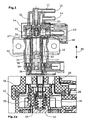
- an electropneumatic converter has a negative pressure port 10, an atmospheric pressure port 12, and a mixed pressure port 14 which is supplied with a mixed pressure of the negative pressure port 10 and the atmospheric pressure port 12.
- the mixing pressure is supplied via the mixing pressure connection 14 to a consumer, in particular an exhaust gas recirculation valve.
- the valve device 18, 28 has a valve body 18 with a valve plate 28.
- the valve body is connected via a diaphragm 20 with a housing 32 such that it is movable in the axial direction 30.
- the membrane 20 is guided in a ring around the valve body 18 and secured in an annular recess of the housing 32 and a housing cover by clamping. Between the valve body 18 and the housing 32 or housing cover, the membrane 20 has a substantially arcuate course.
- the membrane 20 is also secured to the valve body 18 in a recess which leads around the valve body 18 in an annular manner.
- an armature 16 is fixedly connected and also movable in the axial direction.
- the armature 16 comprises a magnetic material and can be moved by applying an electric current to an electromagnet 17.
- the electric coil of the electromagnet 17 is surrounded by an iron sheath 38 for bundling the magnetic field lines. Furthermore, an air gap 40 is formed between the armature 16 and the iron sheath 38, in which an adjustable iron core 34 is arranged such that the length of the air gap 40 is variable. In addition, a second iron core 36 is provided, which projects into a recess 37 of the armature 16. Between the first iron core 34 and the armature 16, a cavity 24 is formed.
- the mixing pressure which is supplied via the mixing pressure connection 14 to a consumer, is established in a valve chamber 11, which is delimited by the membrane 20.
- the mixing pressure results from the pressure which is supplied to the electropneumatic valve via the vacuum connection and the air pressure which is supplied to the electropneumatic valve via the atmospheric pressure connection 12.
- valve plate 28 is integrally formed with the elastomer bellows 19 and thereby resiliently connected to the armature 16. Through the valve plate 28, the vacuum port can be opened and closed.
- the essential feature of the electro-pneumatic converter according to the invention is the damping element 26, which according to Fig. 1 is formed as a bellows made of elastomer, and between a valve seat collar 56 and the coil rib 27 is arranged.
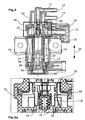
- the damping element 26 is according to the FIGS. 2 and 2a formed as part of the membrane 20, and can with this membrane 20 in a Injection molding be made in one piece. Analogous to the FIGS. 1 and 1a the effect of the damping element 26 takes place in that it is supported on one side on the coil rib 27 and on the opposite side introduces a force into the membrane 20 connected to it.
- the damping element 26 is attached to the ventilation side of the electropneumatic converter, ie, on the side which is directly connected to the atmospheric pressure port 12.
- the damping element 26 is also disposed within the cavity 22.
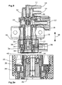
- FIGS. 3 and 3a For example, an elastomeric damping element 26 disposed within a cavity 24 formed between the armature 16 and the iron core 34 is shown.
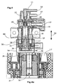
- Figures 4 and 4a show in the same place a damping element of a foam body.
- the damping element may be formed as a damping diaphragm 50 and in particular as an elastomer ring, in which or in which the armature 16 is mounted.
- the elastomeric ring preferably comprises silicone.
- the strokes of the armature 16 and the valve means 18, 28 are damped by mounted on the housing 32 stops 44, 46, 48. These are preferably located at the location of the housing 32 to which the valve body 18 moves upon movement in the direction of the force exerted by the diaphragm 20.
- a thicker damping membrane 50 can be used, which has recesses and is thus made more flexible.
- the valve body 18 For receiving the damping diaphragm 50, the valve body 18 has a preferably annular groove 52.
- the stop 46 has a groove-shaped recess 54 through which ventilation can take place.
- the stops 46, 48 may be formed, for example, of plastic.
- a spring 42 may be formed between the valve body 18 and the housing 32. This is inventively used in conjunction with other damping elements 26, 50.
- damping element for example, only on one side of the armature or the valve means may be provided, or even a plurality of damping elements, which are arranged on one or more sides of the armature and the valve means.
Landscapes
- Engineering & Computer Science (AREA)
- Physics & Mathematics (AREA)
- Electromagnetism (AREA)
- Chemical & Material Sciences (AREA)
- Combustion & Propulsion (AREA)
- Mechanical Engineering (AREA)
- General Engineering & Computer Science (AREA)
- Magnetically Actuated Valves (AREA)
- Exhaust-Gas Circulating Devices (AREA)
Applications Claiming Priority (2)
| Application Number | Priority Date | Filing Date | Title |
|---|---|---|---|
| DE102006038920A DE102006038920B4 (de) | 2006-08-18 | 2006-08-18 | Schwingungs- und pulsationsgedämpfter elektropneumatischer Wandler |
| PCT/EP2007/058009 WO2008019949A1 (de) | 2006-08-18 | 2007-08-02 | Schwingungs- und pulsationsgedämpfter elektropneumatischer wandler |
Publications (2)
| Publication Number | Publication Date |
|---|---|
| EP2052145A1 EP2052145A1 (de) | 2009-04-29 |
| EP2052145B1 true EP2052145B1 (de) | 2011-06-29 |
Family
ID=38616575
Family Applications (1)
| Application Number | Title | Priority Date | Filing Date |
|---|---|---|---|
| EP07802469A Not-in-force EP2052145B1 (de) | 2006-08-18 | 2007-08-02 | Schwingungs- und pulsationsgedämpfter elektropneumatischer wandler |
Country Status (6)
| Country | Link |
|---|---|
| US (1) | US8001952B2 (enExample) |
| EP (1) | EP2052145B1 (enExample) |
| JP (1) | JP5185934B2 (enExample) |
| AT (1) | ATE514852T1 (enExample) |
| DE (1) | DE102006038920B4 (enExample) |
| WO (1) | WO2008019949A1 (enExample) |
Families Citing this family (9)
| Publication number | Priority date | Publication date | Assignee | Title |
|---|---|---|---|---|
| FR2935771B1 (fr) * | 2008-09-09 | 2010-10-08 | Bontaz Centre Sa | Dispositif de commande de l'alimentation d'un systeme avec un fluide |
| DE102009007118B4 (de) * | 2009-02-02 | 2015-07-16 | Pierburg Gmbh | Druckregelventil |
| DE102009032374B3 (de) * | 2009-07-08 | 2010-12-30 | Pierburg Gmbh | Druckregelventil |
| CN102182597B (zh) * | 2011-03-29 | 2013-10-02 | 南京航空航天大学 | 高转速燃油电磁阀及其闭合始点的测量方法 |
| US20120305822A1 (en) * | 2011-05-10 | 2012-12-06 | Delphi Technologies, Inc. | Electronic control valve having an integral non-contact noise mitigation device |
| CN102588153A (zh) * | 2012-03-26 | 2012-07-18 | 无锡隆盛科技有限公司 | 一种真空电磁调节器 |
| DE102013008686A1 (de) * | 2013-05-22 | 2014-11-27 | Volkswagen Aktiengesellschaft | Schaltsaugrohr |
| DE102015102545B4 (de) * | 2015-02-23 | 2017-06-01 | Pierburg Gmbh | Elektropneumatischer Druckwandler |
| US11293564B2 (en) | 2020-06-05 | 2022-04-05 | Automatic Switch Company | Valve silencing choke |
Family Cites Families (15)
| Publication number | Priority date | Publication date | Assignee | Title |
|---|---|---|---|---|
| JPS59183061A (ja) | 1983-04-01 | 1984-10-18 | Nippon Denso Co Ltd | 圧力制御弁 |
| JPS59190461A (ja) * | 1983-04-11 | 1984-10-29 | Nippon Soken Inc | 大気圧補償付負圧制御弁 |
| DE8322570U1 (de) * | 1983-08-05 | 1985-01-17 | Robert Bosch Gmbh, 7000 Stuttgart | Druckregler |
| US4988074A (en) * | 1988-05-17 | 1991-01-29 | Hi-Ram, Inc. | Proportional variable force solenoid control valve |
| DE4110003C1 (en) * | 1991-03-27 | 1992-07-16 | Pierburg Gmbh, 4040 Neuss, De | Electromagnetic pressure transducer for pneumatic control of motor vehicle - has aperture set by adjustable iron@ core having opening for receiving plunger |
| JPH0530665U (ja) * | 1991-09-30 | 1993-04-23 | エヌオーケー株式会社 | 電磁弁 |
| DE4205565C2 (de) | 1992-02-22 | 2002-10-31 | Pierburg Gmbh | Elektropneumatischer Druckwandler |
| DE4329760A1 (de) * | 1993-09-03 | 1995-03-09 | Bosch Gmbh Robert | Elektromagnetisch betätigbares Proportionalventil |
| DE4332117B4 (de) * | 1993-09-22 | 2005-05-04 | Robert Bosch Gmbh | Elektromagnetventil |
| DE4342566B4 (de) | 1993-12-14 | 2004-09-30 | Robert Bosch Gmbh | Elektromagnetisch betätigbares Proportionalventil |
| DE4404740A1 (de) * | 1994-02-15 | 1995-08-17 | Bosch Gmbh Robert | Magnetventil |
| US5513832A (en) | 1994-04-22 | 1996-05-07 | Lectron Products, Inc. | Variable force solenoid valve |
| DE19755956C2 (de) | 1997-12-17 | 2002-06-27 | Pierburg Ag | Ventilschließglied für Druckwandler oder Steuer- und Regelventile |
| DE10327875B4 (de) * | 2002-11-14 | 2005-03-03 | Woco Industrietechnik Gmbh | Tauchankersystem mit einstellbarer magnetischer Durchflutung |
| US7205685B2 (en) * | 2002-11-14 | 2007-04-17 | Woco Industrietechnik Gmbh | Solenoid plunger system with an adjustable magnetic flux |
-
2006
- 2006-08-18 DE DE102006038920A patent/DE102006038920B4/de not_active Expired - Fee Related
-
2007
- 2007-08-02 JP JP2009524998A patent/JP5185934B2/ja not_active Expired - Fee Related
- 2007-08-02 EP EP07802469A patent/EP2052145B1/de not_active Not-in-force
- 2007-08-02 US US12/377,895 patent/US8001952B2/en not_active Expired - Fee Related
- 2007-08-02 WO PCT/EP2007/058009 patent/WO2008019949A1/de not_active Ceased
- 2007-08-02 AT AT07802469T patent/ATE514852T1/de active
Also Published As
| Publication number | Publication date |
|---|---|
| DE102006038920B4 (de) | 2013-01-31 |
| US8001952B2 (en) | 2011-08-23 |
| ATE514852T1 (de) | 2011-07-15 |
| JP5185934B2 (ja) | 2013-04-17 |
| WO2008019949A1 (de) | 2008-02-21 |
| EP2052145A1 (de) | 2009-04-29 |
| US20100163007A1 (en) | 2010-07-01 |
| JP2010501057A (ja) | 2010-01-14 |
| DE102006038920A1 (de) | 2008-02-21 |
Similar Documents
| Publication | Publication Date | Title |
|---|---|---|
| EP2052145B1 (de) | Schwingungs- und pulsationsgedämpfter elektropneumatischer wandler | |
| EP1561225B1 (de) | Tauchankersystem mit einstellbarer magnetischer durchflutung | |
| EP3591273A1 (de) | Magnetventil | |
| EP3478957B1 (de) | Ventil zum eindüsen von gasförmigem kraftstoff | |
| WO2017060079A1 (de) | Druckverteiler für ein kraftfahrzeug | |
| EP3060440B1 (de) | Relaisventil, ventileinrichtung sowie fahrzeug damit | |
| EP1458999B1 (de) | Elektromagnetisches tankentlüftungsventil | |
| DE4439695C2 (de) | Magnetventil und dessen Verwendung | |
| DE102016118341B4 (de) | Verstellorgan für ein Schubumluftventil | |
| EP1456570B1 (de) | Ventil mit dämpfungselement | |
| EP3262326A1 (de) | Elektropneumatischer druckwandler | |
| DE4205565C2 (de) | Elektropneumatischer Druckwandler | |
| DE102010044442B4 (de) | Elektromagnet-Ventilvorrichtung mit zwei Arbeitsanschlüssen | |
| EP3563076B1 (de) | Elektromagnetische klappanker-ventilvorrichtung | |
| EP0624724B1 (de) | Vorrichtung zur Regelung der Leerlaufdrehzahl einer Brennkraftmaschine | |
| EP2268949B1 (de) | Elektrisches umschaltventil | |
| EP1911999A1 (de) | Ventilkörper und zugehöriges Magnetventil | |
| EP1760378B1 (de) | Integrierte Druckwandler-Unterdruck-Stelleinheit | |
| DE102005043969B4 (de) | Ventilvorrichtung zum Steuern eines Fluidstroms | |
| EP2220382B1 (de) | Elektropneumatische steuervorrichtung mit einem steuerschieber, der einen innerhalb einer magnetspule angeordneten magnetabschnitt aufweist | |
| EP3043114B1 (de) | Regelventilvorrichtung | |
| DE10327875B4 (de) | Tauchankersystem mit einstellbarer magnetischer Durchflutung | |
| DE102016107766A1 (de) | Elektromagnetventil sowie Betriebsverfahren | |
| DE102019210284A1 (de) | Magnetventil mit zweiteilig ausgebildetem Stößel | |
| WO2007079969A1 (de) | Längsschieberventil, insbesondere für die verwendung von transkritischen co2 (r 744) klimakreisläufe |
Legal Events
| Date | Code | Title | Description |
|---|---|---|---|
| PUAI | Public reference made under article 153(3) epc to a published international application that has entered the european phase |
Free format text: ORIGINAL CODE: 0009012 |
|
| 17P | Request for examination filed |
Effective date: 20081221 |
|
| AK | Designated contracting states |
Kind code of ref document: A1 Designated state(s): AT BE BG CH CY CZ DE DK EE ES FI FR GB GR HU IE IS IT LI LT LU LV MC MT NL PL PT RO SE SI SK TR |
|
| AX | Request for extension of the european patent |
Extension state: AL BA HR MK RS |
|
| RIN1 | Information on inventor provided before grant (corrected) |
Inventor name: DOHRMANN, ROLF Inventor name: ZURKE, JANUSZ Inventor name: FERNANDES, ALVITO |
|
| GRAJ | Information related to disapproval of communication of intention to grant by the applicant or resumption of examination proceedings by the epo deleted |
Free format text: ORIGINAL CODE: EPIDOSDIGR1 |
|
| GRAP | Despatch of communication of intention to grant a patent |
Free format text: ORIGINAL CODE: EPIDOSNIGR1 |
|
| GRAP | Despatch of communication of intention to grant a patent |
Free format text: ORIGINAL CODE: EPIDOSNIGR1 |
|
| GRAS | Grant fee paid |
Free format text: ORIGINAL CODE: EPIDOSNIGR3 |
|
| GRAA | (expected) grant |
Free format text: ORIGINAL CODE: 0009210 |
|
| AK | Designated contracting states |
Kind code of ref document: B1 Designated state(s): AT BE BG CH CY CZ DE DK EE ES FI FR GB GR HU IE IS IT LI LT LU LV MC MT NL PL PT RO SE SI SK TR |
|
| REG | Reference to a national code |
Ref country code: GB Ref legal event code: FG4D Free format text: NOT ENGLISH |
|
| REG | Reference to a national code |
Ref country code: CH Ref legal event code: EP |
|
| REG | Reference to a national code |
Ref country code: IE Ref legal event code: FG4D Free format text: LANGUAGE OF EP DOCUMENT: GERMAN |
|
| REG | Reference to a national code |
Ref country code: DE Ref legal event code: R096 Ref document number: 502007007572 Country of ref document: DE Effective date: 20110818 |
|
| REG | Reference to a national code |
Ref country code: NL Ref legal event code: VDEP Effective date: 20110629 |
|
| PG25 | Lapsed in a contracting state [announced via postgrant information from national office to epo] |
Ref country code: SE Free format text: LAPSE BECAUSE OF FAILURE TO SUBMIT A TRANSLATION OF THE DESCRIPTION OR TO PAY THE FEE WITHIN THE PRESCRIBED TIME-LIMIT Effective date: 20110629 Ref country code: LT Free format text: LAPSE BECAUSE OF FAILURE TO SUBMIT A TRANSLATION OF THE DESCRIPTION OR TO PAY THE FEE WITHIN THE PRESCRIBED TIME-LIMIT Effective date: 20110629 |
|
| PG25 | Lapsed in a contracting state [announced via postgrant information from national office to epo] |
Ref country code: LV Free format text: LAPSE BECAUSE OF FAILURE TO SUBMIT A TRANSLATION OF THE DESCRIPTION OR TO PAY THE FEE WITHIN THE PRESCRIBED TIME-LIMIT Effective date: 20110629 Ref country code: SI Free format text: LAPSE BECAUSE OF FAILURE TO SUBMIT A TRANSLATION OF THE DESCRIPTION OR TO PAY THE FEE WITHIN THE PRESCRIBED TIME-LIMIT Effective date: 20110629 Ref country code: GR Free format text: LAPSE BECAUSE OF FAILURE TO SUBMIT A TRANSLATION OF THE DESCRIPTION OR TO PAY THE FEE WITHIN THE PRESCRIBED TIME-LIMIT Effective date: 20110930 Ref country code: FI Free format text: LAPSE BECAUSE OF FAILURE TO SUBMIT A TRANSLATION OF THE DESCRIPTION OR TO PAY THE FEE WITHIN THE PRESCRIBED TIME-LIMIT Effective date: 20110629 |
|
| PG25 | Lapsed in a contracting state [announced via postgrant information from national office to epo] |
Ref country code: MT Free format text: LAPSE BECAUSE OF FAILURE TO SUBMIT A TRANSLATION OF THE DESCRIPTION OR TO PAY THE FEE WITHIN THE PRESCRIBED TIME-LIMIT Effective date: 20110629 |
|
| REG | Reference to a national code |
Ref country code: IE Ref legal event code: FD4D |
|
| PG25 | Lapsed in a contracting state [announced via postgrant information from national office to epo] |
Ref country code: IE Free format text: LAPSE BECAUSE OF FAILURE TO SUBMIT A TRANSLATION OF THE DESCRIPTION OR TO PAY THE FEE WITHIN THE PRESCRIBED TIME-LIMIT Effective date: 20110629 Ref country code: NL Free format text: LAPSE BECAUSE OF FAILURE TO SUBMIT A TRANSLATION OF THE DESCRIPTION OR TO PAY THE FEE WITHIN THE PRESCRIBED TIME-LIMIT Effective date: 20110629 Ref country code: IS Free format text: LAPSE BECAUSE OF FAILURE TO SUBMIT A TRANSLATION OF THE DESCRIPTION OR TO PAY THE FEE WITHIN THE PRESCRIBED TIME-LIMIT Effective date: 20111029 Ref country code: CZ Free format text: LAPSE BECAUSE OF FAILURE TO SUBMIT A TRANSLATION OF THE DESCRIPTION OR TO PAY THE FEE WITHIN THE PRESCRIBED TIME-LIMIT Effective date: 20110629 Ref country code: EE Free format text: LAPSE BECAUSE OF FAILURE TO SUBMIT A TRANSLATION OF THE DESCRIPTION OR TO PAY THE FEE WITHIN THE PRESCRIBED TIME-LIMIT Effective date: 20110629 Ref country code: PT Free format text: LAPSE BECAUSE OF FAILURE TO SUBMIT A TRANSLATION OF THE DESCRIPTION OR TO PAY THE FEE WITHIN THE PRESCRIBED TIME-LIMIT Effective date: 20111031 |
|
| BERE | Be: lapsed |
Owner name: PIERBURG G.M.B.H. Effective date: 20110831 |
|
| PG25 | Lapsed in a contracting state [announced via postgrant information from national office to epo] |
Ref country code: PL Free format text: LAPSE BECAUSE OF FAILURE TO SUBMIT A TRANSLATION OF THE DESCRIPTION OR TO PAY THE FEE WITHIN THE PRESCRIBED TIME-LIMIT Effective date: 20110629 Ref country code: RO Free format text: LAPSE BECAUSE OF FAILURE TO SUBMIT A TRANSLATION OF THE DESCRIPTION OR TO PAY THE FEE WITHIN THE PRESCRIBED TIME-LIMIT Effective date: 20110629 Ref country code: SK Free format text: LAPSE BECAUSE OF FAILURE TO SUBMIT A TRANSLATION OF THE DESCRIPTION OR TO PAY THE FEE WITHIN THE PRESCRIBED TIME-LIMIT Effective date: 20110629 Ref country code: CY Free format text: LAPSE BECAUSE OF FAILURE TO SUBMIT A TRANSLATION OF THE DESCRIPTION OR TO PAY THE FEE WITHIN THE PRESCRIBED TIME-LIMIT Effective date: 20110629 |
|
| PG25 | Lapsed in a contracting state [announced via postgrant information from national office to epo] |
Ref country code: MC Free format text: LAPSE BECAUSE OF NON-PAYMENT OF DUE FEES Effective date: 20110831 |
|
| REG | Reference to a national code |
Ref country code: CH Ref legal event code: PL |
|
| PG25 | Lapsed in a contracting state [announced via postgrant information from national office to epo] |
Ref country code: CH Free format text: LAPSE BECAUSE OF NON-PAYMENT OF DUE FEES Effective date: 20110831 Ref country code: LI Free format text: LAPSE BECAUSE OF NON-PAYMENT OF DUE FEES Effective date: 20110831 |
|
| PLBE | No opposition filed within time limit |
Free format text: ORIGINAL CODE: 0009261 |
|
| STAA | Information on the status of an ep patent application or granted ep patent |
Free format text: STATUS: NO OPPOSITION FILED WITHIN TIME LIMIT |
|
| PG25 | Lapsed in a contracting state [announced via postgrant information from national office to epo] |
Ref country code: BE Free format text: LAPSE BECAUSE OF NON-PAYMENT OF DUE FEES Effective date: 20110831 |
|
| 26N | No opposition filed |
Effective date: 20120330 |
|
| PG25 | Lapsed in a contracting state [announced via postgrant information from national office to epo] |
Ref country code: DK Free format text: LAPSE BECAUSE OF FAILURE TO SUBMIT A TRANSLATION OF THE DESCRIPTION OR TO PAY THE FEE WITHIN THE PRESCRIBED TIME-LIMIT Effective date: 20110629 |
|
| REG | Reference to a national code |
Ref country code: DE Ref legal event code: R097 Ref document number: 502007007572 Country of ref document: DE Effective date: 20120330 |
|
| PG25 | Lapsed in a contracting state [announced via postgrant information from national office to epo] |
Ref country code: ES Free format text: LAPSE BECAUSE OF FAILURE TO SUBMIT A TRANSLATION OF THE DESCRIPTION OR TO PAY THE FEE WITHIN THE PRESCRIBED TIME-LIMIT Effective date: 20111010 |
|
| PG25 | Lapsed in a contracting state [announced via postgrant information from national office to epo] |
Ref country code: LU Free format text: LAPSE BECAUSE OF NON-PAYMENT OF DUE FEES Effective date: 20110802 |
|
| PG25 | Lapsed in a contracting state [announced via postgrant information from national office to epo] |
Ref country code: BG Free format text: LAPSE BECAUSE OF FAILURE TO SUBMIT A TRANSLATION OF THE DESCRIPTION OR TO PAY THE FEE WITHIN THE PRESCRIBED TIME-LIMIT Effective date: 20110929 |
|
| PG25 | Lapsed in a contracting state [announced via postgrant information from national office to epo] |
Ref country code: TR Free format text: LAPSE BECAUSE OF FAILURE TO SUBMIT A TRANSLATION OF THE DESCRIPTION OR TO PAY THE FEE WITHIN THE PRESCRIBED TIME-LIMIT Effective date: 20110629 |
|
| REG | Reference to a national code |
Ref country code: AT Ref legal event code: MM01 Ref document number: 514852 Country of ref document: AT Kind code of ref document: T Effective date: 20120831 |
|
| PG25 | Lapsed in a contracting state [announced via postgrant information from national office to epo] |
Ref country code: AT Free format text: LAPSE BECAUSE OF NON-PAYMENT OF DUE FEES Effective date: 20120831 Ref country code: HU Free format text: LAPSE BECAUSE OF FAILURE TO SUBMIT A TRANSLATION OF THE DESCRIPTION OR TO PAY THE FEE WITHIN THE PRESCRIBED TIME-LIMIT Effective date: 20110629 |
|
| REG | Reference to a national code |
Ref country code: FR Ref legal event code: PLFP Year of fee payment: 9 |
|
| PGFP | Annual fee paid to national office [announced via postgrant information from national office to epo] |
Ref country code: DE Payment date: 20150820 Year of fee payment: 9 Ref country code: GB Payment date: 20150824 Year of fee payment: 9 |
|
| PGFP | Annual fee paid to national office [announced via postgrant information from national office to epo] |
Ref country code: FR Payment date: 20150824 Year of fee payment: 9 |
|
| PGFP | Annual fee paid to national office [announced via postgrant information from national office to epo] |
Ref country code: IT Payment date: 20150827 Year of fee payment: 9 |
|
| REG | Reference to a national code |
Ref country code: DE Ref legal event code: R119 Ref document number: 502007007572 Country of ref document: DE |
|
| GBPC | Gb: european patent ceased through non-payment of renewal fee |
Effective date: 20160802 |
|
| REG | Reference to a national code |
Ref country code: FR Ref legal event code: ST Effective date: 20170428 |
|
| PG25 | Lapsed in a contracting state [announced via postgrant information from national office to epo] |
Ref country code: GB Free format text: LAPSE BECAUSE OF NON-PAYMENT OF DUE FEES Effective date: 20160802 Ref country code: DE Free format text: LAPSE BECAUSE OF NON-PAYMENT OF DUE FEES Effective date: 20170301 Ref country code: FR Free format text: LAPSE BECAUSE OF NON-PAYMENT OF DUE FEES Effective date: 20160831 |
|
| PG25 | Lapsed in a contracting state [announced via postgrant information from national office to epo] |
Ref country code: IT Free format text: LAPSE BECAUSE OF NON-PAYMENT OF DUE FEES Effective date: 20160802 |