EP2051767B1 - Needle tip protector housing positioned inside a catheter hub - Google Patents
Needle tip protector housing positioned inside a catheter hub Download PDFInfo
- Publication number
- EP2051767B1 EP2051767B1 EP07786297.7A EP07786297A EP2051767B1 EP 2051767 B1 EP2051767 B1 EP 2051767B1 EP 07786297 A EP07786297 A EP 07786297A EP 2051767 B1 EP2051767 B1 EP 2051767B1
- Authority
- EP
- European Patent Office
- Prior art keywords
- tip protector
- needle
- tip
- wall
- arm
- Prior art date
- Legal status (The legal status is an assumption and is not a legal conclusion. Google has not performed a legal analysis and makes no representation as to the accuracy of the status listed.)
- Active
Links
- 0 CC1*C*CC1 Chemical compound CC1*C*CC1 0.000 description 1
Images

Classifications
-
- A—HUMAN NECESSITIES
- A61—MEDICAL OR VETERINARY SCIENCE; HYGIENE
- A61M—DEVICES FOR INTRODUCING MEDIA INTO, OR ONTO, THE BODY; DEVICES FOR TRANSDUCING BODY MEDIA OR FOR TAKING MEDIA FROM THE BODY; DEVICES FOR PRODUCING OR ENDING SLEEP OR STUPOR
- A61M25/00—Catheters; Hollow probes
- A61M25/01—Introducing, guiding, advancing, emplacing or holding catheters
- A61M25/06—Body-piercing guide needles or the like
- A61M25/0612—Devices for protecting the needle; Devices to help insertion of the needle, e.g. wings or holders
- A61M25/0618—Devices for protecting the needle; Devices to help insertion of the needle, e.g. wings or holders having means for protecting only the distal tip of the needle, e.g. a needle guard
-
- A—HUMAN NECESSITIES
- A61—MEDICAL OR VETERINARY SCIENCE; HYGIENE
- A61M—DEVICES FOR INTRODUCING MEDIA INTO, OR ONTO, THE BODY; DEVICES FOR TRANSDUCING BODY MEDIA OR FOR TAKING MEDIA FROM THE BODY; DEVICES FOR PRODUCING OR ENDING SLEEP OR STUPOR
- A61M25/00—Catheters; Hollow probes
- A61M25/01—Introducing, guiding, advancing, emplacing or holding catheters
- A61M25/06—Body-piercing guide needles or the like
- A61M25/0606—"Over-the-needle" catheter assemblies, e.g. I.V. catheters
-
- A—HUMAN NECESSITIES
- A61—MEDICAL OR VETERINARY SCIENCE; HYGIENE
- A61M—DEVICES FOR INTRODUCING MEDIA INTO, OR ONTO, THE BODY; DEVICES FOR TRANSDUCING BODY MEDIA OR FOR TAKING MEDIA FROM THE BODY; DEVICES FOR PRODUCING OR ENDING SLEEP OR STUPOR
- A61M5/00—Devices for bringing media into the body in a subcutaneous, intra-vascular or intramuscular way; Accessories therefor, e.g. filling or cleaning devices, arm-rests
- A61M5/14—Infusion devices, e.g. infusing by gravity; Blood infusion; Accessories therefor
- A61M5/158—Needles for infusions; Accessories therefor, e.g. for inserting infusion needles, or for holding them on the body
-
- A—HUMAN NECESSITIES
- A61—MEDICAL OR VETERINARY SCIENCE; HYGIENE
- A61M—DEVICES FOR INTRODUCING MEDIA INTO, OR ONTO, THE BODY; DEVICES FOR TRANSDUCING BODY MEDIA OR FOR TAKING MEDIA FROM THE BODY; DEVICES FOR PRODUCING OR ENDING SLEEP OR STUPOR
- A61M5/00—Devices for bringing media into the body in a subcutaneous, intra-vascular or intramuscular way; Accessories therefor, e.g. filling or cleaning devices, arm-rests
- A61M5/178—Syringes
- A61M5/31—Details
- A61M5/32—Needles; Details of needles pertaining to their connection with syringe or hub; Accessories for bringing the needle into, or holding the needle on, the body; Devices for protection of needles
- A61M5/3205—Apparatus for removing or disposing of used needles or syringes, e.g. containers; Means for protection against accidental injuries from used needles
- A61M5/321—Means for protection against accidental injuries by used needles
- A61M5/3243—Means for protection against accidental injuries by used needles being axially-extensible, e.g. protective sleeves coaxially slidable on the syringe barrel
- A61M5/3273—Means for protection against accidental injuries by used needles being axially-extensible, e.g. protective sleeves coaxially slidable on the syringe barrel freely sliding on needle shaft without connection to syringe or needle
-
- A—HUMAN NECESSITIES
- A61—MEDICAL OR VETERINARY SCIENCE; HYGIENE
- A61M—DEVICES FOR INTRODUCING MEDIA INTO, OR ONTO, THE BODY; DEVICES FOR TRANSDUCING BODY MEDIA OR FOR TAKING MEDIA FROM THE BODY; DEVICES FOR PRODUCING OR ENDING SLEEP OR STUPOR
- A61M5/00—Devices for bringing media into the body in a subcutaneous, intra-vascular or intramuscular way; Accessories therefor, e.g. filling or cleaning devices, arm-rests
- A61M5/178—Syringes
- A61M5/31—Details
- A61M5/32—Needles; Details of needles pertaining to their connection with syringe or hub; Accessories for bringing the needle into, or holding the needle on, the body; Devices for protection of needles
- A61M5/3205—Apparatus for removing or disposing of used needles or syringes, e.g. containers; Means for protection against accidental injuries from used needles
- A61M5/321—Means for protection against accidental injuries by used needles
- A61M5/3243—Means for protection against accidental injuries by used needles being axially-extensible, e.g. protective sleeves coaxially slidable on the syringe barrel
- A61M5/3245—Constructional features thereof, e.g. to improve manipulation or functioning
- A61M2005/3247—Means to impede repositioning of protection sleeve from needle covering to needle uncovering position
- A61M2005/325—Means obstructing the needle passage at distal end of a needle protection sleeve
Definitions
- Needle assemblies are generally discussed herein with particular discussions extended to needle assemblies having a tip protector comprising enclosed wall surfaces for preventing contact with the needle tip from a side.
- Insertion procedure for an IV catheter assembly contains four basic steps: (1) the healthcare worker inserts the needle and catheter together into the patient's vein; (2) after insertion into the vein with the needle point, the catheter is forwarded into the vein of the patient by the healthcare worker pushing the catheter with his or her finger; (3) the healthcare worker withdraws the needle by grasping the hub end (opposite the point end) while at the same time applying pressure to the patient's skin at the insertion site with his or her free hand; and (4) the healthcare worker then tapes the now inserted catheter to the patient's skin and connects the exposed end of the catheter (the catheter hub) to the source of the fluid to be administered into the patient's vein.
- the problem is that, immediately after the withdrawal of the needle from the patient's vein, the healthcare worker, who is at this time involved in at least two urgent procedures, must place the exposed needle tip at a nearby location and address the tasks required to accomplish the needle withdrawal. It is at this juncture that the exposed needle tip creates a danger of an accidental needle stick, which, under the circumstances, leaves the healthcare worker vulnerable to the transmission of various dangerous blood-borne pathogens, including AIDS and hepatitis.
- a doctor administering an injection, using a straight needle, a Huber needle, an epidural needle, etc. may place the used needle on a tray for subsequent disposal by a nurse.
- the used needle is a potential source for disease transmissions for those that work near or around the needle. Accordingly, all needles should be covered immediately following use to ensure greater worker safety.
- the procedure for covering the needle tip should be passive, self activating, or at least simple to perform.
- the device for covering the needle should be reliable and robust.
- WO 01/10488 A1 (Arrow International, Inc) relates to a hypodermic needle guard, in particular, to a device for inhibiting intentional contact with the tip of a needle that has a guide wire disposed in a lumen thereof.
- the device comprises a housing having an interior cavity with a portion of the needle extending through the cavity and a pivoting member and a spring located within the cavity to prevent further movement when the needle tip is within the cavity.
- US 2004/0236288 A1 (Howell et al. ) relates to a catheter and introducer needle shield assembly including a catheter adapter and a needle, slidably disposed within the catheter adapter and a needle shield slidably mounted on the needle.
- a canting plate is disposed within the needle shield assembly to restrict distal movement of the needle tip.
- WO 99/98742 discloses a safety IV catheter including a resilient needle guard received in a catheter hub, which reliably and automatically prevents accidental, inadvertent contact with the needle tip after use.
- the needle guard described therein includes a proximal arm or wall including an opening through which the needle passes for axial movement. Upon withdrawal of the needle into the retracted or protected position, the needle guard pivots so as to block access to the distal needle tip and prevent further distal movement of needle tip.
- a tip protector that blocks the needle tip from direct contact with a needle tip.
- the tip protector incorporates side walls for providing shielding the needle tip from view and exposure to blood dripping from the inside of the needle tip .
- a deflector plate is provided to deflect the needle from inadvertently re-emerging from within the tip protector.
- the deflector plate is used, at least in part, to position the tip protector within a housing.
- the resilient engagement allowing for a relatively smoother release without having to reduce typical manufacturing tolerances.
- a tip protector for blocking a needle tip comprising: a tip protector housing positioned inside a hub having an interior surface; a needle passing through the tip protector and the housing; a first arm extending from a distal wall of the tip protector housing biased against the interior surface; a second arm extending from a proximal wall of the tip protector housing biased against the interior surface; and a third arm extending from the proximal wall of the tip protector housing and biased against a side of the needle.
- a tip protector for mounting on a needle to shield a needle tip comprising: a first protector body comprising a proximal wall and an arm extending distally of the proximal wall; said arm further comprising: a distal wall at an end of the arm for blocking a needle tip; a non-uniform arm width for accommodating a needle extending from between the proximal wall and the distal wall; a second protector body attached to the first protector body, the second protector body comprising a distal wall and two side walls defining a cavity for accommodating the first protector body; and a deflector plate comprising a projection projecting into the cavity, the projection and the distal wall at the end of the arm are configured to limit movement of a needle tip from moving distally of the distal wall of the second protector body.
- a tip protector for mounting on a needle to shield a needle tip comprising: a first protector body attached to a second protector body; the first protector body comprising a proximal wall and an arm, which comprises a distal end portion of the arm, extending distally of the proximal wall; the second protector body comprising two side walls and two end walls defining a cavity for accommodating the first protector body; the two side walls each comprising a first edge and a second edge; a deflector plate comprising a projection projecting into the cavity, the deflector plate is configured to deflect and move relative to both the first edge and the second edge; and wherein the projection and the distal end portion of the arm are configured to be on different sides of a needle shaft defined by a centerline when the tip protector is mounted on a needle and the tip protector is in a ready to use position.
- a needle assembly comprising: a housing comprising a wall having an interior wall surface defining a cavity having a tip protector disposed therein; a needle, which has a shaft having a first side and a second side defined by a centerline and a needle tip, passing through the housing and the tip protector; the tip protector comprising a distal wall, two side walls, a proximal wall, a first arm extending from the proximal wall towards the distal wall, a second arm, which is shorter than the first arm, extending from the proximal wall, and a wall opposite the second arm; and wherein the wall opposite the second arm and the second arm are both biased against the interior wall surface of the housing.
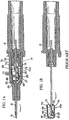
- FIGs. 1A and 1B illustrate a prior art spring clip needle guard shown and described in U.S. Patent No. 6,616,630 to Woehr et al.
- FIGs. 1A and 1B shown herein are labeled and discussed in the '630 patent as FIGs. 4A and 4B .
- the spring clip needle guard 40a includes a distal arm 65 terminating at its upper end in a curved lip 66 and at its lower end in a U-shaped portion 67 which, in the ready position illustrated in FIG. 1A , contacts a bump 68 formed in the lower inner wall of the catheter hub 26.
- a transverse segment 69 having a central opening 70 extends proximally and upwardly and terminates at an upper U-shaped portion 72. As disclosed in the '630 patent, the opening is configured to clamp the needle in a used position, at points d and e, which have been added.
- a proximal end wall 74 having an opening 76 extends vertically from portion 72 and then extends distally in a horizontal lower segment 78, which has an opening 80 through which the lower halves of the distal arm 65 and the transverse segment 69 extend in the ready position of the needle guard.
- Segment 78 at its distal end, extends upwardly at a front wall 82 which has a central opening 84 axially aligned with openings 70, 76.
- the distal front wall 82 extends in the proximal direction in an upper segment 86, which, as shown in FIG. 1A , contacts the upper inner wall of the catheter hub along substantially its entire length.
- the needle shaft passes through openings 70, 76 and 84 and rests on the curved lip 66, which urges the arm 65 against the bump 68 in the lower wall of the catheter hub. That engagement, along with the resilient engagement of the upper segment 86 with the upper interior wall of the catheter hub, retains the spring clip 40a in its ready position within the catheter hub.
- the needle tip 18 moves proximal of the lip 66 and eventually passes below the lip 66.
- the downward force on the arm 65 releases thus allowing the arm 65 to snap upwards to the retracted position illustrated in FIG. 4B , in which the arm 65 and the lip 66 extend over the needle tip 18 to thereby prevent accidental contact with the needle tip.
- the needle guard 40a is clamped onto the needle shaft 16 at points d and e of opening 70 and the needle and needle guard clamped thereto can be readily removed from the catheter hub.
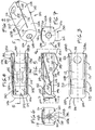
- the tip protector 100 comprises a first protector body (See, also FIG. 5 ) 102 surrounded, at least in part, by a second protector body 104.
- the second protector body 104 comprises a distal wall 106 comprising an opening 108, which is preferably circular in configuration.
- a plurality of walls extend distally of the distal wall 106, which include two side walls 110A, 110B and a deflector wall, plate, or arm 112.
- the second protector body 104 is preferably formed from a single stamped or cut-out stainless steel sheet resembling a "T", which has a circular cut-out 108 at the intersection of the three branches of the "T" for forming the opening 108 on the distal wall 106.
- the intersection of the T-shape sheet is pressed against a metal form or die, such as carbide, which then forms the curvilinear perimeter contour 114 around the perimeter of the distal wall 106 while concurrently pushing the two side walls 110A, 110B and the deflector plate 112 proximally.
- a bottom perimeter contour can also formed by this process.
- the edges 116 of the two side walls 110A, 110B and the deflector plate 112 are formed fitted in the same die used to form the curvilinear perimeter contour 114 of the distal wall 106.
- the intersections 118 between the two side walls 110A, 110B and the deflector plate 112 are generally curved or smooth rather than at right angles (also shown in FIGs. 6 and 7 ).
- the smooth edges 116 allow the tip protector 100 to contact an interior surface of a clip housing or catheter hub over a larger surface area as compared to corners having a simple right-angle, which would result in a single point contact.
- the side walls and deflector plate are preferably close enough together to shield the needle tip from view and catch any drop of blood that may drip from the needle while inside the needle tip.
- a projection or dimple 120 is incorporated on the deflector plate 112 for delimiting needle movement in an activated position, as further discussed below.
- the width of the dimple section 120 extending from one side wall 110A to another side wall 110B, is slightly less than the width of the deflector plate immediately proximally and distally of the dimple section.
- the dissimilar widths along the deflector plate 112 allow the dimple 120 to be formed following formations of the smooth corners 116.
- the tip protector 100 may incorporate right angle corners at the various intersections 118 and the deflector plate 112 having a uniform width, which are less preferred, without deviating from the spirit and scope of the present invention.
- An optional opening 122 may be incorporated on the deflector plate 112 for ease of assembly.
- a pin (not shown) could be inserted through the opening 122 to push the arm 140 ( FIG. 5 ) of the first protector body downwards. This could assist in assembling the butt end of a cannula or needle through the protector.
- the opening is not necessary as the distal wall 150 of the first protector body 102 is formed at an angle thus allowing the butt end of the cannula to simply deflect the distal wall downwards for an automatic assembly.
- FIG. 3 is a top view of the tip protector 100 of FIG. 2 .
- a reduced proximal section 124 is incorporated on the deflector plate 112, which has a smaller width dimension that the section immediately distally.
- a gap 126 is created on each side of the reduced proximal section 124, which is defined in part by each side wall 110A, 110B and the reduced proximal portion 124.
- the two gaps 126 can be filled by keeping the same width the entire length of the deflector plate 112.
- a side wall attachment plate 128A, 128B is incorporated at a proximal end of each side wall 110A, 110B. If a centerline or axis is drawn lengthwise of the tip protector 100, the two side wall attachment plates 128A, 128B are positioned orthogonally of the axis and are generally coplanar. However, the two attachment plates 128A, 128B can overlap and be non-coplanar without deviating from the spirit and scope of the present invention. As further discussed below, the two attachment plates 128A, 128B are means by which the second protector body 104 attaches to the first protector body 102.
- FIG. 4 is a bottom view of the tip protector 100 of FIG. 2 .
- the first protector body 102 is clearly shown positioned between the two side walls 110A, 110B of the second protector body 104.
- an arm 130 for stabilizing the tip protector 100 within a housing or hub is incorporated.
- the arm 130 extends distally from a proximal wall 132 (See also FIG. 5 ) and includes a bend or apex 133 defined by an upstream section 134 positioned at an angle to a downstream section 136 (See also FIG. 5 ).
- the arm 130 is configured to pivot, flex, or cantilevered about a point 138 at a proximal end of the tip protector 100, which acts like a hinge.
- the proximal wall 132 and the two attachment plates 128A, 128B together define a protector proximal end 129.
- An arm 140 of relatively longer length than the arm 130 for stabilizing, for blocking a needle tip also extends from the proximal wall 132.
- the arm 140 comprises an opening 142 and two ribs 144.
- the opening 142 has an oblong shape and the two ribs 144 are formed by a coining process.
- the arm 140 further includes a forearm section 146, a return section 148 ( FIG. 5 ), a distal wall 150 ( FIG. 5 ) for blocking a needle tip, and an end section or finger 152 ( FIG. 5 ) for overlapping a portion of the needle in the used position.
- the forearm section 146, the return section 148, the distal wall 150, and the finger 152 are collectively referred to herein as a distal arm blocking section.
- the section of the arm with the opening 142 is wider than the remaining arm sections. This configuration provides room to not only incorporate the opening 142 but also the two coined ribs 144.
- a tab or flab may be incorporated on each edge of the arm section and then bending them to form two ribs.
- the alternative arm, without the coined ribs, may have a uniform width throughout.
- FIG. 5 is a cross-sectional side view of the tip protector of FIG. 4 taken along line 5-5.
- the two arms 130, 140 can be seen extending from two different edges of the proximal wall 132.
- the two arms originate from opposite side of the needle, viewed from a needle centerline.
- the longer arm 140 extends distally of the proximal wall 132 at an angle and transects the needle axis, with the needle passing through the opening 142 on the arm.
- the short arm 130 does not touch or intersect the needle. More preferably, the end edge 154 of the short arm 130 is spaced apart from the needle, both in a ready to use position and a used position.
- the long arm 140 when the tip protector 100 is in a ready to use position, the long arm 140 is biased radially outwardly towards the short arm 130 and the finger 152 in contact with a side of the needle. To that end, the long arm 140 is flexed, at least in part, about a point 156 at the proximal wall 132 when in abutting contact with a side of the needle.
- the deflector plate 112 is cantilevered from the perimeter contour 114 of the distal wall 106 of the second protector body 104. This allows the whole deflector plate 112, and more specifically the reduced proximal portion 124, to deflect like a springboard.
- the dimension between the apex 133 of the short arm 130 and the rounded edges 116 of the deflector plate 112 should be larger than the internal curvature of a housing the tip protector is to be placed into so that both the deflector plate 112 and the short arm 130 are biased inwardly by the wall surface of the housing.
- the tip protector 100 is mounted inside a housing, such as the catheter hub shown in FIG. 11 , the tip protector is squeezed at the two rounded edges on the deflector plate 112 and the short arm 130. This squeezing action allows the tip protector to be removeably secured to the housing or hub.
- FIG. 6 is an end view of the tip protector of Fig. 5 taken along line 6-6.
- the two side attachment plates 128A, 128B are shown in contact with the proximally facing surface of the proximal wall 132.
- the two attachment plates 128A, 128B are welded, using ultrasound, high frequency welding or laser, to the proximal wall 132.
- An opening 158 is incorporated on the proximal wall 132 of the first protector body 102 for receiving a needle (not shown).
- the two attachment walls 128A, 128B both incorporate cut-outs 160 resembling two semi-circles that together have a larger diameter than the opening 158 on the proximal wall 132.
- the two attachment walls 128A, 128B can overlap one another and each incorporating a separate opening having a larger diameter than the diameter on the opening 158 of the proximal wall.
- FIG. 7 is a front view of the tip protector 100 of FIG. 5 taken along line 7-7.
- the second protector body 104 incorporates a plurality of walled structures, namely the two side walls 110A, 110B and the deflector plate 112, a front wall 106, and two attachment walls 128A, 128B (not shown) to form an enclosure comprising a cavity 155 and a central access opening 162 (See also FIG. 5 ).
- the short arm 130 projects out through the central access opening 162 to provide a contact point between the tip protector and a housing, such as a catheter hub.
- the long arm 140 ( FIG. 5 ) similarly projects out through the central access opening 162 when in a ready-to-use position but moves into the cavity 155 when in a used position, as further discussed below.
- FIG. 8 is a cross-sectional side view of the first protector body 102 of FIG. 1 , shown without the second protector body 104.
- the first protector body 102 is formed from an single integral stainless steel sheet.
- the opening 142 should be stamped and the two ribs 144 coined before the first protector body 102 is formed to the shape shown in FIG. 8 .
- FIG. 9 is a cross-sectional end view of the first protector body 102 of FIG. 8 taken along line 9-9. Part of the two ribs 144, the opening 142 between the two ribs, and the proximal wall 132 are shown.
- FIG. 10 is an end view of the first body section 102 of FIG. 8 taken alone line 10-10. Part of the oblong opening 142 and the distal wall 150 can be seen through the opening 158 on the proximal wall 132. In one exemplary embodiment, four cut-outs 164 are formed at each corner of the proximal wall 132. The cut-outs 164 are configured to reduce the amount of spring force the two arms 130 and 140 generate. The amount of cut out can be varied to obtain a desired spring force.
- the tip protector disclosed herein may be viewed as a device having a housing with three moveable arms 112, 130, and 140.
- the tip protector may also be viewed as having a housing with a deflector plate or arm with a tip protector disposed therein having an arm for blocking a needle tip and an arm, together with the deflector plate, for resiliently securing the tip protector to a hub or clip housing.
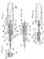
- FIG. 11 is a semi-schematic cross-sectional side view of a catheter assembly 166 incorporating the tip protector 100 of FIGs. 2-10 .
- the catheter assembly 168 comprises a needle hub comprising a needle 170 attached thereto.
- the needle 170 comprises a sharpened needle tip 172, a non-uniform needle section 175 ( FIG. 13 ), and projects through the tip protector 100, the catheter hub 174, and the catheter tube 176.
- the non-uniform needle section 175 may be a crimp, a material build-up, a bend, or combinations thereof.
- the needle hub 168 incorporates a nose section 178 that projects into the interior wall surface 180 of the catheter hub 174.
- the nose section 178 is configured to push the protector proximal end 129 of the tip protector 100 to a desired depth or length inside the cavity 182 defined by the wall surface 180 of the catheter hub 174 in the ready to use position ( FIG. 11 ).
- the cavity 182 includes a recessed section 184, which may extend the entire internal circumference of the cavity along a band or width or a partial circumference, as shown.
- the recessed section 184 provides added space for the distal end of the first body section 102 so as to reduce the amount of compression or biasing force on the finger section 152 and the return section 148. This in turn, reduces the drag between the finger section 152 and the side of the needle 170 during relative movement between the needle and the tip protector 100.
- the needle assembly 166 may be practiced without the recessed section 184, but not as preferred.
- the recessed section 184 comprises a proximal tapered section 186 and a distal tapered section.
- the forearm section 146, the return section 148, and the distal wall 150 of the first body section 102 are all positioned distally of and spaced apart from the proximal tapered section 186.
- the space apart configuration is incorporated as physical contact between the proximal tapered section 186 and the distal arm blocking section is not required to maintain a fixed relationship between the catheter hub 174 and the tip protector 100 during movement of the needle hub 168 relative to the catheter hub.
- contact between the two may be incorporated without deviating from the spirit and scope of the present invention.
- FIG. 12 is a cross-sectional end view of the catheter assembly of FIG. 11 taken along line 12-12, the tip protector 100 is shown contacting the interior wall surface 180 of the catheter hub 174 at the two curbed edges 116 on the deflector plate 112 and two edges of the short arm 130, in the general area of the apex 133.
- the four contact points are shown in FIG. 12 with four contact arrows.
- an arm 130 is cantilevered from a proximal end of the first protector body 102 and another arm 112 is cantilevered from a distal end of the second protector body 104 to retain the tip protector 100 within a catheter hub.
- a tip protector having an arm cantilevered from a proximal wall of a protector housing and a second arm cantilevered from a distal wall of the same protector housing.
- the cantilever arm 112 is eliminated and the two side walls 110A, 110B along with the short arm 130 are configured to removeably secure the alternative tip protector to a housing, such as a catheter hub or a clip housing.
- FIG. 13 is a partial cross-sectional side view of the catheter assembly 166 of FIG. 11 , shown in a used position, with the needle 170 retracted to the right of FIG. 11 .
- the tip protector 100 hence the needle 170, is moved to the used position shown in FIG. 13 by holding the catheter hub 174 in one hand while withdrawing the needle hub 168 to the right of FIG. 11 (or vice-versa, i.e., holding the needle hub 168 while moving the catheter hub 174 to the left of FIG. 11 ).
- the biasing force acting on the arm 140 is removed thus allowing the arm to recoil to its less flexed state, which is shown in FIG. 13 .
- the non-uniform section 175 on the needle 170 contacts the opening 158 and pulls the proximal wall, via the engagement with the perimeter of the opening 158, to the right. If the pulling force on the proximal wall 132 is greater than the friction force between the cantilever arm 112, the short arm 130, and the interior surface 180 of the catheter hub, the friction is overcome and the tip protector 100 disengages from the catheter hub.
- FIG. 14 shows the tip protector 100 removed from the catheter hub 174 and the distal wall 150 blocking the needle tip.
- the tip protector incorporates two side walls 110A, 110B, and a deflector plate 112
- the tip protector covers about three quarters of the circumference of the needle 170 proximate the needle tip.
- the remaining section of the needle 170 proximate the needle tip 172 is also partly covered by the short arm 130 and the distal blocking section of the first protector body 102.
- the needle tip is shielded from view or contact. Blood, which may drip from the needle tip, is configured to be caught by one of the walls.
- the needle 170 could pivot away from the shielding provided by the finger section 152 and manipulated so that it re-emerges out the opening 108 of the distal wall 106 of the second protector body 104.
- the dimple or projection 120 on the deflector plate 112 is configured to inhibit or delimit movement of the needle in the event of a direct or incidental force on the tip protector at or near point 189.
- the projection 120 is configured to prevent movement of the needle tip 172 radially of the finger section 152.
- FIG. 15 is a semi-schematic perspective view of a second protector body 188 provided in accordance with aspects of the present invention.
- the alternative second protector body 188 may cooperate with the first protector body shown in FIGs. 8-10 to form an alternative tip protector.
- the alternative second protector body 188 incorporates a deflector plate 190 comprising a generally curvilinear external surface, a tab 192 formed by making a cut-out 194 on the deflector plate and including two relief points 196.
- the tab 192 like the projection or dimple 120 on the prior second protector body, is configured to prevent a needle from pivoting out from the tip protector internal space.
- the deflector plate 190 is integrally formed to the side walls 110A and 110B. This can be done, for example, using a deep draw forming process. Still alternatively, the two side walls 110A, 110B and the deflector plate 190 may have a notch of cut-out between them.
- a least a portion of the curvilinear external surface of the deflector plate 190 is configured to contact the interior surface of a catheter hub when the same is placed therein as part of a catheter assembly.
- the deflector plate 190 incorporates a flat surface such that only the two side edges 198 with the two side walls 110A, 110B contact the interior surface of the catheter hub or clip housing.
- the tip protector described herein may be used in combination with a sleeve on a needle having a bend such as that shown in U.S. Pat. No. 6,585,704 to Luther et al.
- the tip protector described herein may be used with an outer housing on a needle for use with a syringe, such as that shown in U.S. Pat. No. 6,595,955 to Fergusson et al.
- the tip protector described herein may be used with a grip part for sliding the tip protector along a needle, such as that shown in Ser. No.
Landscapes
- Health & Medical Sciences (AREA)
- Life Sciences & Earth Sciences (AREA)
- Engineering & Computer Science (AREA)
- Hematology (AREA)
- General Health & Medical Sciences (AREA)
- Anesthesiology (AREA)
- Biomedical Technology (AREA)
- Heart & Thoracic Surgery (AREA)
- Veterinary Medicine (AREA)
- Animal Behavior & Ethology (AREA)
- Public Health (AREA)
- Pulmonology (AREA)
- Biophysics (AREA)
- Vascular Medicine (AREA)
- Environmental & Geological Engineering (AREA)
- Infusion, Injection, And Reservoir Apparatuses (AREA)
- Media Introduction/Drainage Providing Device (AREA)
Priority Applications (4)
| Application Number | Priority Date | Filing Date | Title |
|---|---|---|---|
| EP16164681.5A EP3069749B1 (en) | 2006-07-31 | 2007-07-24 | Needle tip protector housing positioned inside a catheter hub |
| PL13157472T PL2604308T3 (pl) | 2006-07-31 | 2007-07-24 | Obudowa ochronna końcówki igły umiejscowiona wewnątrz nasadki cewnika |
| EP13157472.5A EP2604308B2 (en) | 2006-07-31 | 2007-07-24 | Needle tip protector housing positioned inside a catheter hub |
| DK16164681.5T DK3069749T3 (da) | 2006-07-31 | 2007-07-24 | Nålespidsbeskyttelseshus placeret inde i en kateteransats |
Applications Claiming Priority (2)
| Application Number | Priority Date | Filing Date | Title |
|---|---|---|---|
| US11/496,769 US8382718B2 (en) | 2006-07-31 | 2006-07-31 | Needle assembly and components thereof |
| PCT/EP2007/006571 WO2008014908A1 (en) | 2006-07-31 | 2007-07-24 | Needle tip protector housing positioned inside a catheter hub |
Related Child Applications (4)
| Application Number | Title | Priority Date | Filing Date |
|---|---|---|---|
| EP16164681.5A Division EP3069749B1 (en) | 2006-07-31 | 2007-07-24 | Needle tip protector housing positioned inside a catheter hub |
| EP16164681.5A Division-Into EP3069749B1 (en) | 2006-07-31 | 2007-07-24 | Needle tip protector housing positioned inside a catheter hub |
| EP13157472.5A Division EP2604308B2 (en) | 2006-07-31 | 2007-07-24 | Needle tip protector housing positioned inside a catheter hub |
| EP13157472.5A Division-Into EP2604308B2 (en) | 2006-07-31 | 2007-07-24 | Needle tip protector housing positioned inside a catheter hub |
Publications (2)
| Publication Number | Publication Date |
|---|---|
| EP2051767A1 EP2051767A1 (en) | 2009-04-29 |
| EP2051767B1 true EP2051767B1 (en) | 2018-01-24 |
Family
ID=38787645
Family Applications (3)
| Application Number | Title | Priority Date | Filing Date |
|---|---|---|---|
| EP07786297.7A Active EP2051767B1 (en) | 2006-07-31 | 2007-07-24 | Needle tip protector housing positioned inside a catheter hub |
| EP16164681.5A Active EP3069749B1 (en) | 2006-07-31 | 2007-07-24 | Needle tip protector housing positioned inside a catheter hub |
| EP13157472.5A Active EP2604308B2 (en) | 2006-07-31 | 2007-07-24 | Needle tip protector housing positioned inside a catheter hub |
Family Applications After (2)
| Application Number | Title | Priority Date | Filing Date |
|---|---|---|---|
| EP16164681.5A Active EP3069749B1 (en) | 2006-07-31 | 2007-07-24 | Needle tip protector housing positioned inside a catheter hub |
| EP13157472.5A Active EP2604308B2 (en) | 2006-07-31 | 2007-07-24 | Needle tip protector housing positioned inside a catheter hub |
Country Status (12)
| Country | Link |
|---|---|
| US (7) | US8382718B2 (enExample) |
| EP (3) | EP2051767B1 (enExample) |
| JP (3) | JP5491178B2 (enExample) |
| CN (3) | CN102716524B (enExample) |
| BR (2) | BR122013013981A2 (enExample) |
| DE (1) | DE13157472T1 (enExample) |
| DK (1) | DK3069749T3 (enExample) |
| ES (3) | ES2662618T3 (enExample) |
| PL (1) | PL2604308T3 (enExample) |
| PT (1) | PT2604308E (enExample) |
| TW (2) | TWI471150B (enExample) |
| WO (1) | WO2008014908A1 (enExample) |
Cited By (1)
| Publication number | Priority date | Publication date | Assignee | Title |
|---|---|---|---|---|
| USD884160S1 (en) | 2019-02-25 | 2020-05-12 | iMed Technology, Inc. | Huber safety needle |
Families Citing this family (74)
| Publication number | Priority date | Publication date | Assignee | Title |
|---|---|---|---|---|
| US6749588B1 (en) * | 1998-04-09 | 2004-06-15 | Becton Dickinson And Company | Catheter and introducer needle assembly with needle shield |
| DE20210394U1 (de) | 2002-07-04 | 2002-09-12 | B. Braun Melsungen Ag, 34212 Melsungen | Kathetereinführvorrichtung |
| US11083841B2 (en) | 2002-08-09 | 2021-08-10 | Fenwal, Inc. | Needle protector, needle assembly and fluid processing set including the same |
| US8308691B2 (en) | 2006-11-03 | 2012-11-13 | B. Braun Melsungen Ag | Catheter assembly and components thereof |
| US8382718B2 (en) | 2006-07-31 | 2013-02-26 | B. Braun Melsungen Ag | Needle assembly and components thereof |
| JP4994775B2 (ja) | 2006-10-12 | 2012-08-08 | 日本コヴィディエン株式会社 | 針先保護具 |
| US9345836B2 (en) | 2007-10-02 | 2016-05-24 | Medimop Medical Projects Ltd. | Disengagement resistant telescoping assembly and unidirectional method of assembly for such |
| US9656019B2 (en) | 2007-10-02 | 2017-05-23 | Medimop Medical Projects Ltd. | Apparatuses for securing components of a drug delivery system during transport and methods of using same |
| US7967795B1 (en) | 2010-01-19 | 2011-06-28 | Lamodel Ltd. | Cartridge interface assembly with driving plunger |
| US10420880B2 (en) | 2007-10-02 | 2019-09-24 | West Pharma. Services IL, Ltd. | Key for securing components of a drug delivery system during assembly and/or transport and methods of using same |
| BRPI0817907B8 (pt) | 2007-10-02 | 2021-06-22 | Lamodel Ltd | aparelho para administrar uma substância a um indivíduo |
| EP2417997B1 (en) * | 2008-03-17 | 2015-05-20 | Poly Medicure Limited | Needle safety device |
| US12097357B2 (en) | 2008-09-15 | 2024-09-24 | West Pharma. Services IL, Ltd. | Stabilized pen injector |
| US9393369B2 (en) | 2008-09-15 | 2016-07-19 | Medimop Medical Projects Ltd. | Stabilized pen injector |
| US8715249B2 (en) * | 2008-11-18 | 2014-05-06 | Steven A. Dringenberg | Trocar safety cap |
| US8876775B2 (en) * | 2009-11-16 | 2014-11-04 | Steven A. Dringenberg | Needle safety cap |
| DE102009020061A1 (de) * | 2009-05-06 | 2010-11-11 | B. Braun Melsungen Ag | Nadelschutzvorrichtung für eine medizinische Hohlnadel |
| US8323249B2 (en) | 2009-08-14 | 2012-12-04 | The Regents Of The University Of Michigan | Integrated vascular delivery system |
| US8157769B2 (en) | 2009-09-15 | 2012-04-17 | Medimop Medical Projects Ltd. | Cartridge insertion assembly for drug delivery system |
| US10071196B2 (en) | 2012-05-15 | 2018-09-11 | West Pharma. Services IL, Ltd. | Method for selectively powering a battery-operated drug-delivery device and device therefor |
| US10071198B2 (en) | 2012-11-02 | 2018-09-11 | West Pharma. Servicees IL, Ltd. | Adhesive structure for medical device |
| US8348898B2 (en) | 2010-01-19 | 2013-01-08 | Medimop Medical Projects Ltd. | Automatic needle for drug pump |
| WO2011141907A1 (en) | 2010-05-10 | 2011-11-17 | Medimop Medical Projects Ltd. | Low volume accurate injector |
| WO2011146772A1 (en) | 2010-05-19 | 2011-11-24 | Tangent Medical Technologies Llc | Safety needle system operable with a medical device |
| WO2011146769A2 (en) | 2010-05-19 | 2011-11-24 | Tangent Medical Technologies Llc | Integrated vascular delivery system |
| HUE025529T2 (en) * | 2010-07-02 | 2016-04-28 | Sanofi Aventis Deutschland | Safety device for pre-filled syringe and injection device |
| AU2011306446C1 (en) * | 2010-09-21 | 2017-05-18 | Poly Medicure Limited | Catheter assembly with improved safety means |
| USD702834S1 (en) | 2011-03-22 | 2014-04-15 | Medimop Medical Projects Ltd. | Cartridge for use in injection device |
| EP2517751B8 (en) | 2011-04-27 | 2018-02-28 | Kpr U.S., Llc | Safety IV catheter assemblies |
| US9345862B2 (en) | 2011-07-26 | 2016-05-24 | Poly Medicure Limited | Needle tip protector assembly for safety IV catheter assembly |
| US8715250B2 (en) | 2011-09-26 | 2014-05-06 | Covidien Lp | Safety catheter and needle assembly |
| WO2013048975A1 (en) | 2011-09-26 | 2013-04-04 | Covidien Lp | Safety catheter |
| WO2013056223A1 (en) | 2011-10-14 | 2013-04-18 | Covidien Lp | Safety iv catheter assembly |
| US9072827B2 (en) | 2012-03-26 | 2015-07-07 | Medimop Medical Projects Ltd. | Fail safe point protector for needle safety flap |
| SE537334C2 (sv) | 2012-04-27 | 2015-04-07 | Vigmed Ab | Skyddsanordning för nålspets och monteringsanordning |
| US9421323B2 (en) | 2013-01-03 | 2016-08-23 | Medimop Medical Projects Ltd. | Door and doorstop for portable one use drug delivery apparatus |
| US8979802B2 (en) * | 2013-03-15 | 2015-03-17 | B. Braun Melsungen Ag | Safety IV catheter assembly with seal |
| US9011164B2 (en) | 2013-04-30 | 2015-04-21 | Medimop Medical Projects Ltd. | Clip contact for easy installation of printed circuit board PCB |
| US10500376B2 (en) | 2013-06-07 | 2019-12-10 | Becton, Dickinson And Company | IV catheter having external needle shield and internal blood control septum |
| AU2014331691B2 (en) * | 2013-10-10 | 2018-08-02 | Medical Components, Inc | Huber needle assembly with safety capture device |
| US10918837B2 (en) * | 2013-12-04 | 2021-02-16 | B. Braun Melsungen Ag | Safety needle assemblies and related methods |
| EP3102258A4 (en) | 2014-02-04 | 2017-12-27 | ICU Medical, Inc. | Self-priming systems and methods |
| SG11201608545UA (en) | 2014-04-18 | 2016-11-29 | Becton Dickinson Co | Multi-use blood control safety catheter assembly |
| SG11201607989TA (en) * | 2014-05-27 | 2016-12-29 | Braun Melsungen Ag | Blood sampling devices and related methods |
| SG10201406976SA (en) * | 2014-10-27 | 2016-05-30 | Aci Medical Pte Ltd | Intravenous catheter assembly |
| US11511052B2 (en) | 2014-11-10 | 2022-11-29 | Becton, Dickinson And Company | Safety IV catheter with V-clip interlock and needle tip capture |
| JP6640861B2 (ja) | 2015-01-30 | 2020-02-05 | スミスズ メディカル エーエスディー,インコーポレイティド | 解放可能なカテーテルハブ保持具 |
| WO2016123616A1 (en) | 2015-01-30 | 2016-08-04 | Smiths Medical Asd, Inc. | Intravenous catheter assembly design |
| US10293120B2 (en) | 2015-04-10 | 2019-05-21 | West Pharma. Services IL, Ltd. | Redundant injection device status indication |
| US10149943B2 (en) | 2015-05-29 | 2018-12-11 | West Pharma. Services IL, Ltd. | Linear rotation stabilizer for a telescoping syringe stopper driverdriving assembly |
| CN113181477B (zh) | 2015-06-04 | 2023-07-14 | 麦迪麦珀医疗工程有限公司 | 用于药物释放装置的筒插入 |
| US10576207B2 (en) | 2015-10-09 | 2020-03-03 | West Pharma. Services IL, Ltd. | Angled syringe patch injector |
| US9987432B2 (en) | 2015-09-22 | 2018-06-05 | West Pharma. Services IL, Ltd. | Rotation resistant friction adapter for plunger driver of drug delivery device |
| CN108472438B (zh) | 2015-10-09 | 2022-01-28 | 西医药服务以色列分公司 | 至预填充的流体储存器的弯曲流体路径附加装置 |
| US11311674B2 (en) | 2016-01-21 | 2022-04-26 | West Pharma. Services IL, Ltd. | Medicament delivery device comprising a visual indicator |
| CN109310816B (zh) | 2016-01-21 | 2020-04-21 | 西医药服务以色列有限公司 | 针插入和缩回机构 |
| CN109219456B (zh) | 2016-01-21 | 2020-05-15 | 西医药服务以色列有限公司 | 自动注射器中的力牵制 |
| EP4309724A3 (en) | 2016-02-18 | 2024-04-17 | Smiths Medical ASD, Inc. | Closed system catheter |
| US11389597B2 (en) | 2016-03-16 | 2022-07-19 | West Pharma. Services IL, Ltd. | Staged telescopic screw assembly having different visual indicators |
| EP3463526B1 (en) | 2016-06-02 | 2024-08-21 | West Pharma. Services Il, Ltd. | Three position needle retraction |
| US11338090B2 (en) | 2016-08-01 | 2022-05-24 | West Pharma. Services IL, Ltd. | Anti-rotation cartridge pin |
| JP7059251B2 (ja) | 2016-08-01 | 2022-04-25 | ウェスト ファーマ サービシーズ イスラエル リミテッド | ドアの半閉じを防止するスプリング |
| CN106267521B (zh) * | 2016-08-30 | 2023-04-07 | 苏州鱼跃医疗科技有限公司 | 安全装置、导管和引入针组件及留置针 |
| EP3290072B1 (en) * | 2016-09-05 | 2019-04-10 | Roche Diabetes Care GmbH | Device for measuring a fill level of a flexible medicine reser-voir |
| USD808013S1 (en) | 2016-10-27 | 2018-01-16 | Smiths Medical Asd, Inc. | Catheter |
| CN110891640A (zh) | 2017-05-26 | 2020-03-17 | 派珀接入公司 | 导管递送装置、系统和方法 |
| JP6921997B2 (ja) | 2017-05-30 | 2021-08-18 | ウェスト ファーマ サービシーズ イスラエル リミテッド | ウェアラブル注射器のモジュラ駆動トレイン |
| CN109078238A (zh) * | 2017-06-14 | 2018-12-25 | 美敦力公司 | 一种穿刺针防护装置和套管针 |
| CN114470420B (zh) | 2017-12-22 | 2024-08-27 | 西氏医药包装(以色列)有限公司 | 适用于不同尺寸的药筒的注射器 |
| WO2019236956A2 (en) | 2018-06-08 | 2019-12-12 | Smiths Medical Asd, Inc. | Blood sequestration device and method |
| EP4021552A1 (en) | 2019-08-29 | 2022-07-06 | B. Braun Melsungen AG | Extended dwell and midline catheters and related methods |
| US11266792B2 (en) | 2019-10-28 | 2022-03-08 | FGC Holdings Limited | Single use safety needle guard |
| AU2022354117A1 (en) | 2021-09-29 | 2023-10-12 | B. Braun Melsungen Ag | Catheters with guidewire adaptors and related assembly method |
| WO2025087904A1 (en) | 2023-10-23 | 2025-05-01 | B. Braun Melsungen Ag | Peripheral safety catheters and related methods |
Citations (1)
| Publication number | Priority date | Publication date | Assignee | Title |
|---|---|---|---|---|
| US20090054852A1 (en) * | 2006-03-29 | 2009-02-26 | Terumo Kabushiki Kaisha | Protector |
Family Cites Families (85)
| Publication number | Priority date | Publication date | Assignee | Title |
|---|---|---|---|---|
| US3610240A (en) | 1967-06-13 | 1971-10-05 | American Hospital Supply Corp | Intravenous catheter apparatus with catheter telescoped inside puncturing cannula |
| US3510240A (en) * | 1968-10-25 | 1970-05-05 | Magic Chef Inc | Pilot burner |
| US3904033A (en) * | 1974-11-08 | 1975-09-09 | Xomox Corp | Pick-guard |
| US4160450A (en) * | 1977-07-15 | 1979-07-10 | Doherty George O | Outside-the-needle catheter device with needle housing |
| US4795432A (en) * | 1987-02-19 | 1989-01-03 | Karczmer Claude M | Shield assembly for hypodermic injection devices |
| US4747831A (en) * | 1987-04-29 | 1988-05-31 | Phase Medical, Inc. | Cannula insertion set with safety retracting needle |
| US4725267A (en) * | 1987-05-06 | 1988-02-16 | Vaillancourt Vincent L | Post-injection needle sheath |
| US4944725A (en) * | 1987-06-01 | 1990-07-31 | Mcdonald Michael | Safety needle apparatus |
| US4735618A (en) * | 1987-07-20 | 1988-04-05 | Henry E. Szachowicz, Jr. | Protective enclosure for hypodermic syringe |
| US5053107A (en) * | 1987-07-29 | 1991-10-01 | Lydall, Inc. | Ceramic staple fiber and glass fiber paper |
| US4790828A (en) * | 1987-08-07 | 1988-12-13 | Dombrowski Mitchell P | Self-capping needle assembly |
| US4846809A (en) * | 1988-02-29 | 1989-07-11 | Winifred Sims | Needle tip protective device |
| USRE34416E (en) * | 1988-07-11 | 1993-10-19 | Critikon, Inc. | I.V. catheter with self-locating needle guard |
| US4952207A (en) * | 1988-07-11 | 1990-08-28 | Critikon, Inc. | I.V. catheter with self-locating needle guard |
| US4929241A (en) * | 1988-08-05 | 1990-05-29 | Kulli John C | Medical needle puncture guard |
| US4978344A (en) * | 1988-08-11 | 1990-12-18 | Dombrowski Mitchell P | Needle and catheter assembly |
| US4964854A (en) * | 1989-01-23 | 1990-10-23 | Luther Medical Products, Inc. | Intravascular catheter assembly incorporating needle tip shielding cap |
| US5322517A (en) * | 1989-02-01 | 1994-06-21 | Sero-Guard Corporation | Disposable automatic hypodermic needle guard |
| US5662610A (en) * | 1989-02-01 | 1997-09-02 | Sircom; Richard C. | Automatic needle guard tip protection |
| NZ233609A (en) * | 1989-05-17 | 1992-10-28 | Critikon Inc | Over-the-needle catheter assembly; restriction in catheter tube to limit liquid backflow |
| US5092845A (en) | 1989-07-10 | 1992-03-03 | Critikon, Inc. | Catheter with needle gasket |
| US5135504A (en) * | 1989-07-17 | 1992-08-04 | Mclees Donald J | Needle tip guard |
| US5030205A (en) | 1989-12-18 | 1991-07-09 | Critikon, Inc. | Catheter assemblies for prevention of blood leakage |
| US5147327A (en) * | 1990-01-10 | 1992-09-15 | Johnson Gerald W | Hypodermic needle with protective sheath |
| US5049136A (en) * | 1990-01-10 | 1991-09-17 | Johnson Gerald W | Hypodermic needle with protective sheath |
| US5084023A (en) | 1990-03-22 | 1992-01-28 | Critikon, Inc. | Bloodless catheter with self-shielding needle |
| US5558651A (en) * | 1990-04-20 | 1996-09-24 | Becton Dickinson And Company | Apparatus and method for a needle tip cover |
| US5051109A (en) * | 1990-07-16 | 1991-09-24 | Simon Alexander Z | Protector for catheter needle |
| US5085648A (en) * | 1990-09-13 | 1992-02-04 | Becton Dickinson And Company | Dual diameter needle with a smooth transition |
| US5183468A (en) * | 1991-04-02 | 1993-02-02 | Mclees Donald J | Snap ring needle guard |
| US5171229A (en) * | 1991-04-15 | 1992-12-15 | Mcneil Michael B | Needle tip cover |
| US5215528C1 (en) * | 1992-02-07 | 2001-09-11 | Becton Dickinson Co | Catheter introducer assembly including needle tip shield |
| US5279570A (en) * | 1992-09-22 | 1994-01-18 | Wayne State University | Needle assembly with a movable stylet controlled by a spacer mechanism |
| US5370623A (en) * | 1993-03-01 | 1994-12-06 | Kreamer; Jeffry W. | Catheter with protective cover and method of catheterization |
| US5697907A (en) * | 1993-07-20 | 1997-12-16 | Graphic Controls Corporation | Safety catheter |
| US5584809A (en) * | 1993-07-20 | 1996-12-17 | Graphic Controls Corporation | Safety catheter |
| US5312371A (en) * | 1993-07-27 | 1994-05-17 | Dombrowski Mitchell P | Method of making a needle sleeve assembly |
| US5344408A (en) * | 1993-08-06 | 1994-09-06 | Becton, Dickinson And Company | Break-away safety shield for needle cannula |
| US5334158A (en) * | 1993-12-20 | 1994-08-02 | Mclees Donald J | Automatic needle tip guard for standard hypodermic needles |
| US5584818A (en) * | 1994-08-22 | 1996-12-17 | Morrison; David | Safety hypodermic needle and shielding cap assembly |
| GB2292525B (en) * | 1994-08-24 | 1998-07-01 | Sterimatic Holdings Ltd | Catheter placement units |
| US5423766A (en) * | 1994-08-26 | 1995-06-13 | Becton, Dickinson And Company | Safety shield having spring tether |
| US5503107A (en) | 1994-10-28 | 1996-04-02 | Satcher; Johnny | Pet carrier |
| US5501675A (en) * | 1994-12-27 | 1996-03-26 | Becton, Dickinson And Company | Safety catheter assembly having safety stop push button |
| US5599310A (en) * | 1995-06-07 | 1997-02-04 | Johnson & Johnson Medical, Inc. | I.V. catheter assembly with automatic cannula tip guard |
| US5584810A (en) * | 1995-07-11 | 1996-12-17 | Becton Dickinson And Company | Needle point guard assembly |
| US5879337A (en) * | 1997-02-27 | 1999-03-09 | Injectimed, Inc. | Needle tip guard for hypodermic needles |
| US5738665A (en) * | 1996-09-26 | 1998-04-14 | Becton, Dickinson And Company | Shield and actuator for needles |
| US6117108A (en) * | 1997-08-20 | 2000-09-12 | Braun Melsungen Ag | Spring clip safety IV catheter |
| US6616630B1 (en) * | 1997-08-20 | 2003-09-09 | B. Braun Melsungen A.G. | Spring clip safety IV catheter |
| US8211070B2 (en) | 1997-08-20 | 2012-07-03 | B. Braun Melsungen Ag | Spring clip safety IV catheter |
| US7507222B2 (en) | 1998-04-09 | 2009-03-24 | Becton, Dickinson And Company | Method and apparatus for shielding the tip of a catheter introducer needle |
| US6004294A (en) * | 1998-04-09 | 1999-12-21 | Becton, Dickinson And Company | Catheter and introducer needle assembly with needle shield |
| US6652490B2 (en) * | 1998-04-09 | 2003-11-25 | Becton Dickinson And Company | Catheter and introducer needle assembly with compact needle shield |
| US6749588B1 (en) * | 1998-04-09 | 2004-06-15 | Becton Dickinson And Company | Catheter and introducer needle assembly with needle shield |
| US6280419B1 (en) * | 1999-08-09 | 2001-08-28 | Arrow International, Inc. | Hypodermic needle guard |
| DE29921084U1 (de) * | 1999-12-01 | 2000-02-17 | B. Braun Melsungen Ag, 34212 Melsungen | Kurzkatheter |
| US6322537B1 (en) | 1999-12-30 | 2001-11-27 | Ethicon, Inc. | Safety intravenous catheter |
| US6595954B1 (en) † | 2000-03-13 | 2003-07-22 | Luther Research Partners, Llc | Insertion needle and soft catheter system with tip protector |
| ATE362383T1 (de) * | 2000-06-09 | 2007-06-15 | Becton Dickinson Co | Katheter und einführnadel-anordnung mit nadelschutz |
| JP2002085558A (ja) | 2000-09-19 | 2002-03-26 | Terumo Corp | 穿刺具および留置針組立体 |
| AU2105402A (en) * | 2000-12-18 | 2002-07-01 | Terumo Corp | Protector and storage needle assembly |
| US6585704B2 (en) | 2001-01-29 | 2003-07-01 | B. Braun Medical, Inc. | Method of retaining a tip protector on a needle with a curved tip |
| JP2002248168A (ja) * | 2001-02-26 | 2002-09-03 | Terumo Corp | 留置針組立体 |
| US7004927B2 (en) * | 2001-03-15 | 2006-02-28 | Specialized Health Products, Inc. | Safety shield for medical needles |
| US6902546B2 (en) * | 2001-03-15 | 2005-06-07 | Specialized Health Products, Inc. | Safety shield for medical needles |
| US6595955B2 (en) * | 2001-03-15 | 2003-07-22 | Specialized Health Products, Inc. | Safety shield for medical needles |
| DE20106697U1 (de) * | 2001-04-18 | 2001-10-31 | B. Braun Melsungen Ag, 34212 Melsungen | Kathetereinführvorrichtung |
| US6623458B2 (en) * | 2001-09-26 | 2003-09-23 | B. Braun Melsungen, Ag | Spring launched needle safety clip |
| US6652486B2 (en) * | 2001-09-27 | 2003-11-25 | Medex, Inc. | Safety catheter |
| US20040049155A1 (en) * | 2002-06-06 | 2004-03-11 | Schramm John B. | Needle tip protector |
| ES2383587T3 (es) * | 2002-06-20 | 2012-06-22 | Becton, Dickinson And Company | Catéter y conjunto de aguja de introductor con protección de aguja |
| JP2004113394A (ja) * | 2002-09-25 | 2004-04-15 | Terumo Corp | プロテクタ |
| DK1610854T3 (da) * | 2003-04-08 | 2008-12-08 | Medex Inc | Sikkerhedsnål og kateterindretning |
| US7696401B2 (en) * | 2003-07-31 | 2010-04-13 | Evonik Stockhausen, Inc. | Absorbent materials and absorbent articles incorporating such absorbent materials |
| US20050075609A1 (en) * | 2003-10-01 | 2005-04-07 | Latona Patrick C. | Protective needle clips |
| DE20316804U1 (de) | 2003-10-31 | 2005-03-10 | B. Braun Melsungen Ag | Kathetervorrichtung |
| US7226434B2 (en) * | 2003-10-31 | 2007-06-05 | Tyco Healthcare Group Lp | Safety shield |
| MXPA06009272A (es) † | 2004-02-13 | 2007-02-02 | Smiths Medical Asd Inc | Protector para la punta de una aguja. |
| US7513888B2 (en) * | 2004-02-17 | 2009-04-07 | Smiths Medical Asd, Inc. | Needle guards |
| US7651476B2 (en) * | 2004-09-28 | 2010-01-26 | B. Braun Medical Inc. | Protective clips |
| WO2006062983A1 (en) † | 2004-12-07 | 2006-06-15 | Becton Dickinson And Company | Needle capture mechanisms |
| US7632243B2 (en) * | 2005-08-08 | 2009-12-15 | Smiths Medical Asd, Inc. | Duckbill catheter release mechanism |
| US20070073221A1 (en) * | 2005-08-08 | 2007-03-29 | Bialecki Dennis M | Needle guard mechanism with leaf spring |
| US8382718B2 (en) * | 2006-07-31 | 2013-02-26 | B. Braun Melsungen Ag | Needle assembly and components thereof |
-
2006
- 2006-07-31 US US11/496,769 patent/US8382718B2/en active Active
-
2007
- 2007-07-12 TW TW102148741A patent/TWI471150B/zh active
- 2007-07-12 TW TW096125332A patent/TWI464001B/zh active
- 2007-07-24 JP JP2009522142A patent/JP5491178B2/ja active Active
- 2007-07-24 ES ES07786297.7T patent/ES2662618T3/es active Active
- 2007-07-24 CN CN201210085004.5A patent/CN102716524B/zh active Active
- 2007-07-24 EP EP07786297.7A patent/EP2051767B1/en active Active
- 2007-07-24 EP EP16164681.5A patent/EP3069749B1/en active Active
- 2007-07-24 CN CN201210085005XA patent/CN102716525B/zh active Active
- 2007-07-24 ES ES13157472T patent/ES2433146T5/es active Active
- 2007-07-24 PL PL13157472T patent/PL2604308T3/pl unknown
- 2007-07-24 BR BRBR122013013981-8A patent/BR122013013981A2/pt not_active Application Discontinuation
- 2007-07-24 ES ES16164681T patent/ES2735756T3/es active Active
- 2007-07-24 EP EP13157472.5A patent/EP2604308B2/en active Active
- 2007-07-24 CN CN2007800366891A patent/CN101522248B/zh active Active
- 2007-07-24 DE DE13157472.5T patent/DE13157472T1/de active Pending
- 2007-07-24 WO PCT/EP2007/006571 patent/WO2008014908A1/en not_active Ceased
- 2007-07-24 DK DK16164681.5T patent/DK3069749T3/da active
- 2007-07-24 PT PT131574725T patent/PT2604308E/pt unknown
- 2007-07-24 BR BRPI0714954A patent/BRPI0714954B8/pt active IP Right Grant
-
2012
- 2012-09-05 US US13/604,089 patent/US8460249B2/en active Active
- 2012-09-12 JP JP2012200176A patent/JP5727435B2/ja active Active
- 2012-09-12 JP JP2012200177A patent/JP5727436B2/ja active Active
-
2013
- 2013-03-15 US US13/842,968 patent/US8784387B2/en active Active
-
2014
- 2014-05-23 US US14/286,756 patent/US9387307B2/en active Active
-
2015
- 2015-03-04 US US14/638,720 patent/US10376677B2/en active Active
-
2016
- 2016-09-19 US US15/269,583 patent/US10912928B2/en active Active
-
2018
- 2018-10-29 US US16/174,007 patent/US11612722B2/en active Active
Patent Citations (1)
| Publication number | Priority date | Publication date | Assignee | Title |
|---|---|---|---|---|
| US20090054852A1 (en) * | 2006-03-29 | 2009-02-26 | Terumo Kabushiki Kaisha | Protector |
Cited By (1)
| Publication number | Priority date | Publication date | Assignee | Title |
|---|---|---|---|---|
| USD884160S1 (en) | 2019-02-25 | 2020-05-12 | iMed Technology, Inc. | Huber safety needle |
Also Published As
Similar Documents
| Publication | Publication Date | Title |
|---|---|---|
| US11612722B2 (en) | Needle assembly and components thereof | |
| US12121679B2 (en) | Intravenous catheter assembly with safety clip | |
| CN105939753A (zh) | 安全针组件和相关方法 | |
| JP7512300B2 (ja) | 静脈内カテーテル装置 | |
| HK1177156B (en) | Needle tip protector housing positioned inside a catheter hub | |
| HK1177157B (en) | Needle tip protector housing positioned inside a catheter hub |
Legal Events
| Date | Code | Title | Description |
|---|---|---|---|
| PUAI | Public reference made under article 153(3) epc to a published international application that has entered the european phase |
Free format text: ORIGINAL CODE: 0009012 |
|
| 17P | Request for examination filed |
Effective date: 20090223 |
|
| AK | Designated contracting states |
Kind code of ref document: A1 Designated state(s): AT BE BG CH CY CZ DE DK EE ES FI FR GB GR HU IE IS IT LI LT LU LV MC MT NL PL PT RO SE SI SK TR |
|
| AX | Request for extension of the european patent |
Extension state: AL BA HR MK RS |
|
| DAX | Request for extension of the european patent (deleted) | ||
| 17Q | First examination report despatched |
Effective date: 20141008 |
|
| REG | Reference to a national code |
Ref country code: DE Ref legal event code: R079 Ref document number: 602007053815 Country of ref document: DE Free format text: PREVIOUS MAIN CLASS: A61M0025060000 Ipc: A61M0005158000 |
|
| RIC1 | Information provided on ipc code assigned before grant |
Ipc: A61M 5/158 20060101AFI20170804BHEP Ipc: A61M 5/32 20060101ALI20170804BHEP Ipc: A61M 25/06 20060101ALI20170804BHEP |
|
| GRAP | Despatch of communication of intention to grant a patent |
Free format text: ORIGINAL CODE: EPIDOSNIGR1 |
|
| INTG | Intention to grant announced |
Effective date: 20170921 |
|
| GRAJ | Information related to disapproval of communication of intention to grant by the applicant or resumption of examination proceedings by the epo deleted |
Free format text: ORIGINAL CODE: EPIDOSDIGR1 |
|
| GRAR | Information related to intention to grant a patent recorded |
Free format text: ORIGINAL CODE: EPIDOSNIGR71 |
|
| GRAS | Grant fee paid |
Free format text: ORIGINAL CODE: EPIDOSNIGR3 |
|
| GRAA | (expected) grant |
Free format text: ORIGINAL CODE: 0009210 |
|
| INTC | Intention to grant announced (deleted) | ||
| INTG | Intention to grant announced |
Effective date: 20171213 |
|
| AK | Designated contracting states |
Kind code of ref document: B1 Designated state(s): AT BE BG CH CY CZ DE DK EE ES FI FR GB GR HU IE IS IT LI LT LU LV MC MT NL PL PT RO SE SI SK TR |
|
| REG | Reference to a national code |
Ref country code: GB Ref legal event code: FG4D |
|
| REG | Reference to a national code |
Ref country code: CH Ref legal event code: EP |
|
| REG | Reference to a national code |
Ref country code: AT Ref legal event code: REF Ref document number: 965421 Country of ref document: AT Kind code of ref document: T Effective date: 20180215 |
|
| REG | Reference to a national code |
Ref country code: IE Ref legal event code: FG4D |
|
| REG | Reference to a national code |
Ref country code: DE Ref legal event code: R096 Ref document number: 602007053815 Country of ref document: DE |
|
| REG | Reference to a national code |
Ref country code: ES Ref legal event code: FG2A Ref document number: 2662618 Country of ref document: ES Kind code of ref document: T3 Effective date: 20180409 |
|
| REG | Reference to a national code |
Ref country code: NL Ref legal event code: MP Effective date: 20180124 |
|
| REG | Reference to a national code |
Ref country code: LT Ref legal event code: MG4D |
|
| PG25 | Lapsed in a contracting state [announced via postgrant information from national office to epo] |
Ref country code: NL Free format text: LAPSE BECAUSE OF FAILURE TO SUBMIT A TRANSLATION OF THE DESCRIPTION OR TO PAY THE FEE WITHIN THE PRESCRIBED TIME-LIMIT Effective date: 20180124 |
|
| REG | Reference to a national code |
Ref country code: FR Ref legal event code: PLFP Year of fee payment: 12 |
|
| PG25 | Lapsed in a contracting state [announced via postgrant information from national office to epo] |
Ref country code: LT Free format text: LAPSE BECAUSE OF FAILURE TO SUBMIT A TRANSLATION OF THE DESCRIPTION OR TO PAY THE FEE WITHIN THE PRESCRIBED TIME-LIMIT Effective date: 20180124 Ref country code: FI Free format text: LAPSE BECAUSE OF FAILURE TO SUBMIT A TRANSLATION OF THE DESCRIPTION OR TO PAY THE FEE WITHIN THE PRESCRIBED TIME-LIMIT Effective date: 20180124 Ref country code: CY Free format text: LAPSE BECAUSE OF FAILURE TO SUBMIT A TRANSLATION OF THE DESCRIPTION OR TO PAY THE FEE WITHIN THE PRESCRIBED TIME-LIMIT Effective date: 20180124 |
|
| PG25 | Lapsed in a contracting state [announced via postgrant information from national office to epo] |
Ref country code: LV Free format text: LAPSE BECAUSE OF FAILURE TO SUBMIT A TRANSLATION OF THE DESCRIPTION OR TO PAY THE FEE WITHIN THE PRESCRIBED TIME-LIMIT Effective date: 20180124 Ref country code: SE Free format text: LAPSE BECAUSE OF FAILURE TO SUBMIT A TRANSLATION OF THE DESCRIPTION OR TO PAY THE FEE WITHIN THE PRESCRIBED TIME-LIMIT Effective date: 20180124 Ref country code: IS Free format text: LAPSE BECAUSE OF FAILURE TO SUBMIT A TRANSLATION OF THE DESCRIPTION OR TO PAY THE FEE WITHIN THE PRESCRIBED TIME-LIMIT Effective date: 20180524 Ref country code: PL Free format text: LAPSE BECAUSE OF FAILURE TO SUBMIT A TRANSLATION OF THE DESCRIPTION OR TO PAY THE FEE WITHIN THE PRESCRIBED TIME-LIMIT Effective date: 20180124 Ref country code: GR Free format text: LAPSE BECAUSE OF FAILURE TO SUBMIT A TRANSLATION OF THE DESCRIPTION OR TO PAY THE FEE WITHIN THE PRESCRIBED TIME-LIMIT Effective date: 20180425 Ref country code: BG Free format text: LAPSE BECAUSE OF FAILURE TO SUBMIT A TRANSLATION OF THE DESCRIPTION OR TO PAY THE FEE WITHIN THE PRESCRIBED TIME-LIMIT Effective date: 20180424 |
|
| REG | Reference to a national code |
Ref country code: DE Ref legal event code: R097 Ref document number: 602007053815 Country of ref document: DE |
|
| PG25 | Lapsed in a contracting state [announced via postgrant information from national office to epo] |
Ref country code: EE Free format text: LAPSE BECAUSE OF FAILURE TO SUBMIT A TRANSLATION OF THE DESCRIPTION OR TO PAY THE FEE WITHIN THE PRESCRIBED TIME-LIMIT Effective date: 20180124 Ref country code: RO Free format text: LAPSE BECAUSE OF FAILURE TO SUBMIT A TRANSLATION OF THE DESCRIPTION OR TO PAY THE FEE WITHIN THE PRESCRIBED TIME-LIMIT Effective date: 20180124 |
|
| PG25 | Lapsed in a contracting state [announced via postgrant information from national office to epo] |
Ref country code: DK Free format text: LAPSE BECAUSE OF FAILURE TO SUBMIT A TRANSLATION OF THE DESCRIPTION OR TO PAY THE FEE WITHIN THE PRESCRIBED TIME-LIMIT Effective date: 20180124 Ref country code: CZ Free format text: LAPSE BECAUSE OF FAILURE TO SUBMIT A TRANSLATION OF THE DESCRIPTION OR TO PAY THE FEE WITHIN THE PRESCRIBED TIME-LIMIT Effective date: 20180124 Ref country code: SK Free format text: LAPSE BECAUSE OF FAILURE TO SUBMIT A TRANSLATION OF THE DESCRIPTION OR TO PAY THE FEE WITHIN THE PRESCRIBED TIME-LIMIT Effective date: 20180124 |
|
| PLBE | No opposition filed within time limit |
Free format text: ORIGINAL CODE: 0009261 |
|
| STAA | Information on the status of an ep patent application or granted ep patent |
Free format text: STATUS: NO OPPOSITION FILED WITHIN TIME LIMIT |
|
| 26N | No opposition filed |
Effective date: 20181025 |
|
| PG25 | Lapsed in a contracting state [announced via postgrant information from national office to epo] |
Ref country code: SI Free format text: LAPSE BECAUSE OF FAILURE TO SUBMIT A TRANSLATION OF THE DESCRIPTION OR TO PAY THE FEE WITHIN THE PRESCRIBED TIME-LIMIT Effective date: 20180124 |
|
| REG | Reference to a national code |
Ref country code: CH Ref legal event code: PL |
|
| PG25 | Lapsed in a contracting state [announced via postgrant information from national office to epo] |
Ref country code: MC Free format text: LAPSE BECAUSE OF FAILURE TO SUBMIT A TRANSLATION OF THE DESCRIPTION OR TO PAY THE FEE WITHIN THE PRESCRIBED TIME-LIMIT Effective date: 20180124 Ref country code: LU Free format text: LAPSE BECAUSE OF NON-PAYMENT OF DUE FEES Effective date: 20180724 |
|
| REG | Reference to a national code |
Ref country code: BE Ref legal event code: MM Effective date: 20180731 |
|
| REG | Reference to a national code |
Ref country code: IE Ref legal event code: MM4A |
|
| PG25 | Lapsed in a contracting state [announced via postgrant information from national office to epo] |
Ref country code: IE Free format text: LAPSE BECAUSE OF NON-PAYMENT OF DUE FEES Effective date: 20180724 Ref country code: CH Free format text: LAPSE BECAUSE OF NON-PAYMENT OF DUE FEES Effective date: 20180731 Ref country code: LI Free format text: LAPSE BECAUSE OF NON-PAYMENT OF DUE FEES Effective date: 20180731 |
|
| PG25 | Lapsed in a contracting state [announced via postgrant information from national office to epo] |
Ref country code: BE Free format text: LAPSE BECAUSE OF NON-PAYMENT OF DUE FEES Effective date: 20180731 |
|
| REG | Reference to a national code |
Ref country code: AT Ref legal event code: UEP Ref document number: 965421 Country of ref document: AT Kind code of ref document: T Effective date: 20180124 |
|
| PG25 | Lapsed in a contracting state [announced via postgrant information from national office to epo] |
Ref country code: MT Free format text: LAPSE BECAUSE OF NON-PAYMENT OF DUE FEES Effective date: 20180724 |
|
| PG25 | Lapsed in a contracting state [announced via postgrant information from national office to epo] |
Ref country code: TR Free format text: LAPSE BECAUSE OF FAILURE TO SUBMIT A TRANSLATION OF THE DESCRIPTION OR TO PAY THE FEE WITHIN THE PRESCRIBED TIME-LIMIT Effective date: 20180124 |
|
| PG25 | Lapsed in a contracting state [announced via postgrant information from national office to epo] |
Ref country code: PT Free format text: LAPSE BECAUSE OF FAILURE TO SUBMIT A TRANSLATION OF THE DESCRIPTION OR TO PAY THE FEE WITHIN THE PRESCRIBED TIME-LIMIT Effective date: 20180124 Ref country code: HU Free format text: LAPSE BECAUSE OF FAILURE TO SUBMIT A TRANSLATION OF THE DESCRIPTION OR TO PAY THE FEE WITHIN THE PRESCRIBED TIME-LIMIT; INVALID AB INITIO Effective date: 20070724 |
|
| P01 | Opt-out of the competence of the unified patent court (upc) registered |
Effective date: 20230511 |
|
| PGFP | Annual fee paid to national office [announced via postgrant information from national office to epo] |
Ref country code: ES Payment date: 20250819 Year of fee payment: 19 |
|
| PGFP | Annual fee paid to national office [announced via postgrant information from national office to epo] |
Ref country code: DE Payment date: 20250722 Year of fee payment: 19 |
|
| PGFP | Annual fee paid to national office [announced via postgrant information from national office to epo] |
Ref country code: IT Payment date: 20250731 Year of fee payment: 19 |
|
| PGFP | Annual fee paid to national office [announced via postgrant information from national office to epo] |
Ref country code: GB Payment date: 20250724 Year of fee payment: 19 |
|
| PGFP | Annual fee paid to national office [announced via postgrant information from national office to epo] |
Ref country code: FR Payment date: 20250723 Year of fee payment: 19 Ref country code: AT Payment date: 20250721 Year of fee payment: 19 |