EP2051016A2 - Storage type hot water supply system - Google Patents
Storage type hot water supply system Download PDFInfo
- Publication number
- EP2051016A2 EP2051016A2 EP20080166422 EP08166422A EP2051016A2 EP 2051016 A2 EP2051016 A2 EP 2051016A2 EP 20080166422 EP20080166422 EP 20080166422 EP 08166422 A EP08166422 A EP 08166422A EP 2051016 A2 EP2051016 A2 EP 2051016A2
- Authority
- EP
- European Patent Office
- Prior art keywords
- water
- hot water
- temperature
- hot
- storage tank
- Prior art date
- Legal status (The legal status is an assumption and is not a legal conclusion. Google has not performed a legal analysis and makes no representation as to the accuracy of the status listed.)
- Granted
Links
- XLYOFNOQVPJJNP-UHFFFAOYSA-N water Substances O XLYOFNOQVPJJNP-UHFFFAOYSA-N 0.000 title claims abstract description 2282
- 238000010438 heat treatment Methods 0.000 claims abstract description 156
- 238000004891 communication Methods 0.000 claims description 228
- 230000008859 change Effects 0.000 claims description 36
- CURLTUGMZLYLDI-UHFFFAOYSA-N Carbon dioxide Chemical compound O=C=O CURLTUGMZLYLDI-UHFFFAOYSA-N 0.000 claims description 22
- 229910002092 carbon dioxide Inorganic materials 0.000 claims description 11
- 239000001569 carbon dioxide Substances 0.000 claims description 11
- 230000009466 transformation Effects 0.000 description 31
- 239000003507 refrigerant Substances 0.000 description 25
- 238000010586 diagram Methods 0.000 description 22
- 230000004913 activation Effects 0.000 description 13
- 230000003247 decreasing effect Effects 0.000 description 13
- 230000008878 coupling Effects 0.000 description 9
- 238000010168 coupling process Methods 0.000 description 9
- 238000005859 coupling reaction Methods 0.000 description 9
- 230000002093 peripheral effect Effects 0.000 description 9
- 239000000463 material Substances 0.000 description 7
- 230000001105 regulatory effect Effects 0.000 description 6
- 230000002123 temporal effect Effects 0.000 description 6
- 230000001276 controlling effect Effects 0.000 description 5
- 238000001514 detection method Methods 0.000 description 5
- 239000006185 dispersion Substances 0.000 description 5
- 230000009467 reduction Effects 0.000 description 5
- 230000004044 response Effects 0.000 description 5
- 238000009835 boiling Methods 0.000 description 4
- 230000007246 mechanism Effects 0.000 description 4
- 230000000991 decompressive effect Effects 0.000 description 3
- 238000009792 diffusion process Methods 0.000 description 3
- 230000005855 radiation Effects 0.000 description 3
- 239000011347 resin Substances 0.000 description 3
- 229920005989 resin Polymers 0.000 description 3
- 239000002184 metal Substances 0.000 description 2
- 238000000638 solvent extraction Methods 0.000 description 2
- 239000003643 water by type Substances 0.000 description 2
- 239000004215 Carbon black (E152) Substances 0.000 description 1
- 230000003213 activating effect Effects 0.000 description 1
- KYKAJFCTULSVSH-UHFFFAOYSA-N chloro(fluoro)methane Chemical compound F[C]Cl KYKAJFCTULSVSH-UHFFFAOYSA-N 0.000 description 1
- 238000013461 design Methods 0.000 description 1
- 230000006866 deterioration Effects 0.000 description 1
- 238000005553 drilling Methods 0.000 description 1
- 238000005265 energy consumption Methods 0.000 description 1
- 230000004907 flux Effects 0.000 description 1
- 229930195733 hydrocarbon Natural products 0.000 description 1
- 150000002430 hydrocarbons Chemical class 0.000 description 1
- 238000011017 operating method Methods 0.000 description 1
- 238000012545 processing Methods 0.000 description 1
- 230000000087 stabilizing effect Effects 0.000 description 1
- 239000002470 thermal conductor Substances 0.000 description 1
Images


Classifications
-
- F—MECHANICAL ENGINEERING; LIGHTING; HEATING; WEAPONS; BLASTING
- F24—HEATING; RANGES; VENTILATING
- F24D—DOMESTIC- OR SPACE-HEATING SYSTEMS, e.g. CENTRAL HEATING SYSTEMS; DOMESTIC HOT-WATER SUPPLY SYSTEMS; ELEMENTS OR COMPONENTS THEREFOR
- F24D17/00—Domestic hot-water supply systems
- F24D17/02—Domestic hot-water supply systems using heat pumps
-
- F—MECHANICAL ENGINEERING; LIGHTING; HEATING; WEAPONS; BLASTING
- F24—HEATING; RANGES; VENTILATING
- F24D—DOMESTIC- OR SPACE-HEATING SYSTEMS, e.g. CENTRAL HEATING SYSTEMS; DOMESTIC HOT-WATER SUPPLY SYSTEMS; ELEMENTS OR COMPONENTS THEREFOR
- F24D11/00—Central heating systems using heat accumulated in storage masses
- F24D11/02—Central heating systems using heat accumulated in storage masses using heat pumps
- F24D11/0214—Central heating systems using heat accumulated in storage masses using heat pumps water heating system
-
- F—MECHANICAL ENGINEERING; LIGHTING; HEATING; WEAPONS; BLASTING
- F24—HEATING; RANGES; VENTILATING
- F24D—DOMESTIC- OR SPACE-HEATING SYSTEMS, e.g. CENTRAL HEATING SYSTEMS; DOMESTIC HOT-WATER SUPPLY SYSTEMS; ELEMENTS OR COMPONENTS THEREFOR
- F24D19/00—Details
- F24D19/10—Arrangement or mounting of control or safety devices
- F24D19/1006—Arrangement or mounting of control or safety devices for water heating systems
- F24D19/1051—Arrangement or mounting of control or safety devices for water heating systems for domestic hot water
- F24D19/1054—Arrangement or mounting of control or safety devices for water heating systems for domestic hot water the system uses a heat pump
-
- F—MECHANICAL ENGINEERING; LIGHTING; HEATING; WEAPONS; BLASTING
- F24—HEATING; RANGES; VENTILATING
- F24D—DOMESTIC- OR SPACE-HEATING SYSTEMS, e.g. CENTRAL HEATING SYSTEMS; DOMESTIC HOT-WATER SUPPLY SYSTEMS; ELEMENTS OR COMPONENTS THEREFOR
- F24D19/00—Details
- F24D19/10—Arrangement or mounting of control or safety devices
- F24D19/1006—Arrangement or mounting of control or safety devices for water heating systems
- F24D19/1066—Arrangement or mounting of control or safety devices for water heating systems for the combination of central heating and domestic hot water
- F24D19/1072—Arrangement or mounting of control or safety devices for water heating systems for the combination of central heating and domestic hot water the system uses a heat pump
-
- F—MECHANICAL ENGINEERING; LIGHTING; HEATING; WEAPONS; BLASTING
- F24—HEATING; RANGES; VENTILATING
- F24H—FLUID HEATERS, e.g. WATER OR AIR HEATERS, HAVING HEAT-GENERATING MEANS, e.g. HEAT PUMPS, IN GENERAL
- F24H4/00—Fluid heaters characterised by the use of heat pumps
- F24H4/02—Water heaters
- F24H4/04—Storage heaters
-
- F—MECHANICAL ENGINEERING; LIGHTING; HEATING; WEAPONS; BLASTING
- F24—HEATING; RANGES; VENTILATING
- F24H—FLUID HEATERS, e.g. WATER OR AIR HEATERS, HAVING HEAT-GENERATING MEANS, e.g. HEAT PUMPS, IN GENERAL
- F24H9/00—Details
- F24H9/12—Arrangements for connecting heaters to circulation pipes
- F24H9/13—Arrangements for connecting heaters to circulation pipes for water heaters
- F24H9/133—Storage heaters
-
- F—MECHANICAL ENGINEERING; LIGHTING; HEATING; WEAPONS; BLASTING
- F28—HEAT EXCHANGE IN GENERAL
- F28D—HEAT-EXCHANGE APPARATUS, NOT PROVIDED FOR IN ANOTHER SUBCLASS, IN WHICH THE HEAT-EXCHANGE MEDIA DO NOT COME INTO DIRECT CONTACT
- F28D20/00—Heat storage plants or apparatus in general; Regenerative heat-exchange apparatus not covered by groups F28D17/00 or F28D19/00
- F28D20/0034—Heat storage plants or apparatus in general; Regenerative heat-exchange apparatus not covered by groups F28D17/00 or F28D19/00 using liquid heat storage material
- F28D20/0039—Heat storage plants or apparatus in general; Regenerative heat-exchange apparatus not covered by groups F28D17/00 or F28D19/00 using liquid heat storage material with stratification of the heat storage material
-
- F—MECHANICAL ENGINEERING; LIGHTING; HEATING; WEAPONS; BLASTING
- F24—HEATING; RANGES; VENTILATING
- F24D—DOMESTIC- OR SPACE-HEATING SYSTEMS, e.g. CENTRAL HEATING SYSTEMS; DOMESTIC HOT-WATER SUPPLY SYSTEMS; ELEMENTS OR COMPONENTS THEREFOR
- F24D2220/00—Components of central heating installations excluding heat sources
- F24D2220/04—Sensors
- F24D2220/042—Temperature sensors
-
- F—MECHANICAL ENGINEERING; LIGHTING; HEATING; WEAPONS; BLASTING
- F24—HEATING; RANGES; VENTILATING
- F24D—DOMESTIC- OR SPACE-HEATING SYSTEMS, e.g. CENTRAL HEATING SYSTEMS; DOMESTIC HOT-WATER SUPPLY SYSTEMS; ELEMENTS OR COMPONENTS THEREFOR
- F24D2240/00—Characterizing positions, e.g. of sensors, inlets, outlets
- F24D2240/26—Vertically distributed at fixed positions, e.g. multiple sensors distributed over the height of a tank, or a vertical inlet distribution pipe having a plurality of orifices
-
- F—MECHANICAL ENGINEERING; LIGHTING; HEATING; WEAPONS; BLASTING
- F28—HEAT EXCHANGE IN GENERAL
- F28D—HEAT-EXCHANGE APPARATUS, NOT PROVIDED FOR IN ANOTHER SUBCLASS, IN WHICH THE HEAT-EXCHANGE MEDIA DO NOT COME INTO DIRECT CONTACT
- F28D20/00—Heat storage plants or apparatus in general; Regenerative heat-exchange apparatus not covered by groups F28D17/00 or F28D19/00
- F28D2020/0065—Details, e.g. particular heat storage tanks, auxiliary members within tanks
- F28D2020/0069—Distributing arrangements; Fluid deflecting means
-
- Y—GENERAL TAGGING OF NEW TECHNOLOGICAL DEVELOPMENTS; GENERAL TAGGING OF CROSS-SECTIONAL TECHNOLOGIES SPANNING OVER SEVERAL SECTIONS OF THE IPC; TECHNICAL SUBJECTS COVERED BY FORMER USPC CROSS-REFERENCE ART COLLECTIONS [XRACs] AND DIGESTS
- Y02—TECHNOLOGIES OR APPLICATIONS FOR MITIGATION OR ADAPTATION AGAINST CLIMATE CHANGE
- Y02E—REDUCTION OF GREENHOUSE GAS [GHG] EMISSIONS, RELATED TO ENERGY GENERATION, TRANSMISSION OR DISTRIBUTION
- Y02E60/00—Enabling technologies; Technologies with a potential or indirect contribution to GHG emissions mitigation
- Y02E60/14—Thermal energy storage
Definitions
- the present invention relates to a storage type hot water supply system in which hot and cold water is boiled with use of a heat pump cycle and the boiled water is stored in the hot water storage tank.
- a storage type hot water supply system of this type there is known a storage type hot water supply system in which hot and cold water including low temperature water (5°C, for example) is taken out from the lower side of a hot water storage tank, high temperature water (90°C, for example) obtained by boiling hot and cold water with use of a heat pump cycle is returned to the hot water storage tank through the upper side portion of the hot water storage tank, and intermediate temperature water generated through temperature diffusion of the hot and cold water in the hot water storage tank is taken out to the exterior with use of a water intake tube provided while vertically extended in the hot water storage tank so as to be used for the hot water supply (refer to JP 2006-57916 A ).
- the water intake tube has a double tube structure in which an outer cylinder or an inner cylinder is rotatable, water intake holes capable of communicating with each other at predetermined rotating positions are provided at different heights in a circumference of each of the outer cylinder and the inner cylinder, and an outer cylinder or an inner cylinder is rotated so that the intermediate temperature water stored to the predetermined height in the hot water storage tank is taken out.
- the intermediate temperature water can be taken out only from a single portion at a predetermined height.
- the intermediate temperature water in the hot water storage tank becomes lower than the required hot water supply temperature (50°C, for example)
- the intermediate temperature water cannot be used as water for hot water supply even though being taken out from the hot water storage tank, and is left as it is in the sealed hot water storage tank. Therefore, the proportion of the intermediate temperature water of the temperature lower than the required hot water supply temperature is large in the hot water storage tank. Accordingly, the proportion of the high temperature water is decreased, and hence there arises a problem of lacking high temperature water.
- a storage type hot water supply system including a hot water storage tank for storing hot and cold water; a heating means for heating the hot and cold water fed from the hot water storage tank; a water intake tube body provided in the hot water storage tank while extended in an upper and lower direction, for guiding the hot and cold water to an exterior; and a hot water tap to which the hot and cold water taken out to the exterior of the hot water storage tank is guided, the water intake tube body being provided with at least an upper water-intake hole formed near a top of the hot water storage tank and an intermediate water-intake hole formed lower than the upper water-intake hole.
- the storage type hot water supply system of the present invention even when the temperature of the intermediate temperature water in the hot water storage tank becomes lower than the required hot water supply temperature, the intermediate temperature water can be taken out from the hot water storage tank so as to be used as water for hot water supply. Therefore, the proportion of the intermediate temperature water occupying the hot water storage tank can be substantially reduced, whereby it is possible to overcome the lack of high temperature water in the hot water storage tank and to secure high COP.
- FIG. 1 is a structural diagram of a storage type hot water supply system according to Embodiment 1 of the present invention.
- the storage type hot water supply system includes a hot water storage tank unit 1 having a hot water storage tank 2 for storing hot and cold water, a heat pump unit 3 as a heater for heating the hot and cold water in the hot water storage tank 2, and a hot water tap 4 used in the kitchen, the restroom, and the like.
- a heat pump refrigerant circuit of the heat pump unit 3 includes a compressor, a refrigerant-water heat exchanger as a condenser, an electronic expansion valve, and an evaporator of forced air-cooled type.
- An operation of one cycle is performed in which carbon dioxide as a natural refrigerant compressed in the compressor is subjected to heat radiation in the refrigerant-water heat exchanger so as to be liquidized, subjected to decompressive expansion in the electronic expansion valve, vaporized in the evaporator owing to atmospheric heat, and then flows into the compressor again.
- a low temperature water take-out pipe 9 connects the bottom of the hot water storage tank 2 and the heat pump unit 3 to each other. Further, a high temperature water returning pipe 10 connects the top of the hot water storage tank 2 and the heat pump unit 3 to each other.
- the high temperature water returning pipe 10 is provided with a temperature sensor 23 and a high temperature water inflow valve 6.
- low temperature water (5°C, for example) is heated to obtain high temperature water (90°C, for example) through an intermediation of the refrigerant-water heat exchanger in the heat pump refrigerant circuit.
- a cylindrical water intake tube 38 which is extended in the upper and lower direction (vertical direction) and has a sealed bottom portion.
- a hot water temperature sensor 34 for detecting the temperature in the upper and lower direction of the hot and cold water in the hot water storage tank 2.
- five hot water temperature sensors 34a, 34b, 34c, 34d, and 34e are attached at predetermined intervals in the upper and lower direction.
- a water flow pipe 27 is connected to the upper end portion of the water intake tube 38 as a water intake tube body.
- the other end portion of the water flow pipe 27 is connected to the first valve portion of a high temperature water mixing three-way valve 28.
- the second valve portion of the high temperature water mixing three-way valve 28 is connected to one end portion of a hot water outlet pipe 7.
- the other end portion of the hot water outlet pipe 7 is connected to the upper portion of the hot water storage tank 2, and the high temperature water in the hot water storage tank 2 flows out to the exterior through the hot water outlet pipe 7.
- the third valve portion of the high temperature water mixing three-way valve 28 is connected to one end portion of a first downstream valve pipe 5.
- a hot and cold water temperature sensor 29 for detecting a temperature of hot and cold water which flows through the first downstream valve pipe 5 is attached to the first downstream valve pipe 5.
- the other end portion of the first downstream valve pipe 5 is connected to the first valve portion of a low temperature water mixing three-way valve 30.
- the second valve portion of the low temperature water mixing three-way valve 30 is connected to a second downstream valve pipe 32.
- the hot water supply temperature sensor 33 is attached near the low temperature water mixing three-way valve 30 of the second downstream valve pipe 32, and the hot water tap 4 is attached downstream of the second downstream valve pipe 32.
- the third valve portion of the low temperature water mixing three-way valve 30 is connected to the hot water supply pipe 31.
- the hot water supply pipe 31 is connected to a water supply pipe 8.
- a pressure pump (not shown) is mounted to the water supply pipe 8, and low temperature water is pumped into the hot water storage tank 2 and also flows through the hot water supply pipe 31 with the driving of the pressure pump.
- the temperature of the low temperature water is detected with use of a supplied water temperature sensor 37 attached to the water supply pipe 8.
- FIG. 2 is an overall perspective view of the water intake tube 38 as a water intake tube body illustrated in FIG. 1 .
- the water intake tube 38 as a water intake tube body is provided with an upper water-intake hole 40 near the top of the hot water storage tank 2 storing high temperature water 15, and with an intermediate water-intake hole 43 formed lower than the upper water-intake hole 40.
- the intermediate water-intake hole 43 is provided at a height at which intermediate temperature water 16 is easily stored in the hot water storage tank 2. Further, the opening area of the upper water-intake hole 40 is larger than the opening area of the intermediate water-intake hole 43.
- Hot and cold water is filled in the hot water storage tank 2, and the high temperature water 15, the intermediate temperature water 16, and low temperature water 17 are stored in the stated order from the top.
- the temperature of the high temperature water 15 is approximately 90°C which is obtained through heating in the heat pump unit 3
- the temperature of the low temperature water 17 is approximately 5°C which is obtained from the hot and cold water flowing through the water supply pipe 8.
- the intermediate temperature water 16 is stored with a temperature gradient due to thermal diffusion from the high temperature water 15.
- the temperature difference between the intermediate temperature water 16 and the high temperature water to be obtained is small when compared with the case of heating the low temperature water 17. Accordingly, the COP of the heat pump unit 3 is lower when compared with the case of heating the hot and cold water. Therefore, in order to secure high COP, it is necessary to feed the intermediate temperature water 16 to the heat pump unit 3 so as to be used as water for hot water supply instead of being heated therein.
- the hot water temperature sensors 34b, 34c, and 34d detect 90°C, 40°C, and 5°C, respectively, it can be determined that the intermediate temperature water exists near the height of the hot water temperature sensor 34c because the temperature detected by the hot water temperature sensor 34c is higher than 5°C and lower than 90°C. Further, when the multiple hot water temperature sensors 34 detect the temperature higher than 5°C and lower than 90°C, it may be determined that the intermediate temperature water exists at the position of one of the hot water temperature sensors 34, which indicates a temperature approximate to the required hot water supply temperature.
- the hot water temperature sensors 34c and 34d detect 90°C and 5°C, respectively, and when none of the other hot water temperature sensors 34 detects the temperature higher than 5°C and lower than 90°C, it may be determined that the intermediate temperature water exists at a midpoint of the hot water temperature sensors 34c and 34d between which the temperature difference is largest.
- the intermediate temperature water 16 of 40°C exists at the height of the hot water temperature sensor 34c
- the intermediate temperature water 16 is taken out from the intermediate water-intake hole 43 with use of the water intake tube 38.
- the upper water-intake hole 40 is provided on the upper side of the tank, and hence the high temperature water 15 is taken out from the upper water-intake hole 40 simultaneously therewith.
- FIG. 3 is a graph showing a temporal change of the temperature of hot and cold water in the case where the inventors of the present invention take out the hot and cold water in the hot water storage tank 2 with use of the water intake tube 38.
- the abscissa axis indicates the time elapsed from the start of taking-out of hot and cold water through the water intake tube 38, and the ordinate axis indicates the temperature change of hot and cold water taken out through the water intake tube 38.
- the thick line in the graph indicates the correlation between the elapsed time and the temperature change in the case of this embodiment where hot and cold water is taken out from the upper water-intake hole 40 and the intermediate water-intake hole 43, and the thin line in the graph indicates the correlation therebetween in the case where hot and cold water is taken out from only the intermediate water-intake hole 43.
- the temperature distribution in the height direction of the intermediate temperature water 16 widely ranges from approximately 5C° to 90C°. Further, in some operating methods for the storage type hot water supply system, the amount of the intermediate temperature water 16 may be small with respect to the total amount of hot and cold water stored in the tank.
- the low temperature water 17 is resupplied through the water supply pipe 8 by an amount of hot and cold water having flown out from the hot water storage tank 2. Then, the low temperature water 17 reaches the water level of the intermediate water-intake hole 43, and hence the temperature of the hot and cold water is abruptly decreased in accordance with the passage of time. As a matter of course, the temperature of the hot and cold water thus taken out immediately becomes lower than 50°C set as a required hot water supply temperature.
- the temperature of the high temperature water 15 is substantially fixed at 90°C set as a temperature obtained by heating.
- the intermediate temperature water 16 involving wide range of temperature change and the high temperature water 15 fixed at a substantially constant temperature are simultaneously taken out.
- the temperature decrease of the hot and cold water becomes general, and hence the time required for reaching the required hot water supply temperature is shortened.
- the temperature of the hot and cold water thus taken out becomes lower than the required hot water supply temperature depends on the temperatures of the high temperature water 15 and the intermediate temperature water 16 and the flow rate ratio therebetween and on the required hot water supply temperature.
- the temperature of the hot and cold water to be taken out can be also set to be equal to or higher than the required hot water supply temperature.
- the temperature of the hot and cold water taken out through the water intake tube 38 is gradually decreased to the required hot water supply temperature.
- the low temperature water mixing three-way valve 30 is activated in response to the signal from the hot water supply temperature sensor 33.
- the hot and cold water taken out through the water intake tube 38 and the low temperature water supplied from the hot water supply pipe 31 are mixed with each other, whereby hot and cold water at the required hot water supply temperature is supplied within a short period of time as water for hot water supply via the second downstream valve pipe 32 and the hot water tap 4.
- the high temperature water mixing three-way valve 28 is activated so that the high temperature water 15 is taken out through the hot water outlet pipe 7 instead of the water intake tube 38.
- the high temperature water 15 and the low temperature water supplied from the hot water supply pipe 31 are mixed with each other in the low temperature water mixing three-way valve 30 so as to be supplied as water for hot water supply via the second downstream valve pipe 32 and the hot water tap 4.
- the control of the temperature of hot water to be supplied is conducted through the adjustment of the opening areas of the first valve portion and the third valve portion of the low temperature water mixing three-way valve 30 conducted in response to the signal from the hot water supply temperature sensor 33.
- the low temperature water 17 is supplied from the lower side of the hot water storage tank 2 through the water supply pipe 8, the amount of which corresponds to an amount of the hot and cold water taken out from the hot water storage tank 2.
- the low temperature water 17 is taken out via the low temperature water intake pipe 9 from the lower side of the hot water storage tank 2.
- the high temperature water heated in the heat pump unit 3 is returned from the upper side of the hot water storage tank 2 via the high temperature water returning pipe 10 and the high temperature water inflow valve 6.
- carbon dioxide as a natural refrigerant is used in the heat pump unit 3.
- low temperature water can be heated to obtain high temperature water of approximately 90°C.
- supercritical carbon dioxide With use of supercritical carbon dioxide in the heat pump cycle, the low temperature water can be heated to obtain the high temperature water with high energy efficiency.
- the temperature change of hot and cold water taken out from the hot water storage tank 2 can be reduced in accordance with the passage of time when the high temperature water 15 and the intermediate temperature water 16 are taken out from the hot water storage tank 2.
- the temperature control with use of the low temperature water mixing three-way valve 30 for control of the required hot water supply temperature is facilitated.
- the intermediate temperature water 16 is taken out simultaneously with the high temperature water 15 so as to be supplied as water for hot water supply.
- the proportion of the high temperature water is not decreased in accordance therewith, the lack of the high temperature water 15 in the hot water storage tank 2 is overcome, and a high COP is secured in the heat pump unit 3.
- the temperature of hot and cold water taken out from the hot water storage tank 2 with use of the water intake tube 38 is set to be higher than the required hot water supply temperature.
- the temperature of the hot and cold water taken out through the water intake tube 38 can be risen to a temperature higher than the required hot water supply temperature, owing to the high temperature water mixing three-way valve 28 activated so as to increase the amount of the high temperature water 15 through the hot water outlet pipe 7.
- control of each of the flow rate ratios between the hot and cold water taken out from the hot water storage tank 2 and the high temperature water or the low temperature water is described which is conducted with use of the three-way valves including the high temperature water mixing three-way valve 28 or the low temperature water mixing three-way valve 30.
- two valves may be used instead of the three-way valve so as to control the flow rate ratios.
- the opening area of the upper water-intake hole 40 is larger than the opening area of the intermediate water-intake hole 43.
- the opening areas of the upper water-intake hole 40 and the intermediate water-intake hole 43 may be equal to each other.
- the opening area of the intermediate water-intake hole 43 may be larger than the opening area of the upper water-intake hole 40.
- the temperature of the hot and cold water taken out from the water intake tube 38 is more likely to become lower than the required hot water supply temperature.
- the temperature change of the hot and cold water taken out through the water intake tube 38 can be reduced when compared with the case of taking out only the intermediate temperature water 16, thereby facilitating the temperature control of water for hot water supply.
- the numbers of the upper water-intake holes 40 and the intermediate water-intake holes 43 may be changed so as to control the proportion of the flow rate between the high temperature water 15 and the intermediate temperature water 16 which are taken out through the water intake tube 38.
- the lower end portion of the water intake tube 38 may not be subjected to closing so as to use the lower end surface as the intermediate water-intake hole 43 from which the intermediate temperature water 16 is taken out. In this case, it is possible to omit closing of the lower end surface of the water intake tube and hole drilling for forming the intermediate water-intake hole 43, and to thereby achieve cost reduction.
- the opening area of the intermediate water-intake hole 43 can be easily adjusted.
- the five hot water temperature sensors 34a, 34b, 34c, 34d, and 34e are provided on the circumferential side surface of the hot water storage tank 2.
- the position and temperature of the intermediate temperature water 16 can be more accurately detected.
- it is effective to mount in the height direction the hot water temperature sensors 34 at intervals each of which is equal to or smaller than 100 mm and which are separated from each other with respect to the position of the center of the intermediate water-intake hole 43, the length of interval being determined with reference to the layer thickness of approximately 100 mm of the main intermediate temperature water.
- the hot water temperature sensors 34a, 34b, 34c, 34d, and 34e may be arranged at equal intervals in the height direction, or may be arranged at random in the height direction.
- the detection points of the three hot water temperature sensors 34b, 34c, and 34d are used so as to determine the position of the intermediate temperature water 16.
- the position of the intermediate temperature water 16 can be more accurately determined.
- the position of the intermediate temperature water may be determined with use of a single temperature sensor while involving deterioration in the detection accuracy. In this case, the control for comparing a large number of detection points with each other is omitted, and hence it is possible to achieve simplification of the control and increase in processing speed.
- the temperature of the wall surface detected with use of each of the hot water temperature sensors 34 mounted to the outer peripheral surface (side surface) of the hot water storage tank 2 is described as a temperature of hot and cold water in the hot water storage tank 2.
- the hot water temperature sensors 34 may be mounted to the inner peripheral surface (side surface) of the hot water storage tank 2 so as to directly detect the temperature of the hot and cold water in the hot water storage tank 2.
- a water intake tube 38 having an L-shape may be used.
- the water intake tube 38 protrudes at the leading end portion thereof from the side wall of the hot water storage tank 2, and is provided with the upper water-intake hole 40 formed at the position corresponding to the upper side of the hot water storage tank 2, and with the intermediate water-intake hole 43 formed at the position corresponding to the middle of the hot water storage tank 2. It is possible to take out the water intake tube 38 from the side wall of the hot water storage tank 2 with use of the water intake tube 38, and to thereby increase the degree of design freedom.
- FIG. 10 is a structural diagram of a storage type hot water supply system according to Embodiment 2 of the present invention.
- a water intake tube 38 as a water intake tube body formed of the outer cylinder 25 and the inner cylinder 26 which are overlapped with each other.
- the water intake tube 38 includes the outer cylinder 25 and the inner cylinder 26 slidably provided inside the outer cylinder 25 in the circumferential direction.
- the upper portion of the inner cylinder 26 is provided with an upper communication hole 42, and the upper portion of the inner cylinder 26 is covered with an upper communication portion 21.
- the leading end portion of the water flow pipe 27 is passed through the side surface of the upper communication portion 21.
- a drive motor 35 is mounted to the top portion of the inner cylinder 26, and the inner cylinder 26 is rotated in the circumferential direction through driving of the drive motor 35.
- the inner cylinder 26 is rotated through driving of the drive motor 35, and hence it is possible to change the opening areas of the upper water-intake hole 12a and the intermediate water-intake hole 12b of the water intake tube 38, which are formed by overlapping an upper hole portion 39a and an intermediate hole portion 39b provided to the outer cylinder 25 with an upper hole portion 41 a and an intermediate hole portion 41 b provided to the inner cylinder 26, respectively.
- the intermediate temperature water 16 in the hot water storage tank 2 is determined to exist at the position of the intermediate water-intake hole 12b with use of the hot water temperature sensors 34a, 34b, 34c, 34d, and 34e, the high temperature water 15 and the intermediate temperature water 16 are taken out from the upper water-intake hole 12a and the intermediate water-intake hole 12b, respectively, and hot and cold water is taken out from the hot water storage tank 2 via the upper communication hole 42 and the upper communication portion 21 of the inner cylinder 26.
- the opening areas of the upper water-intake hole 12a and the intermediate water-intake hole 12b are changed with the drive motor such that the temperature of the hot and cold water does not become lower than a required hot water supply temperature. In this manner, the flow rate ratio between the high temperature water 15 taken out from the upper water-intake hole 12a and the intermediate temperature water 16 taken out from the intermediate water-intake hole 12b is controlled.
- the hot and cold water thus taken out reaches the low temperature water mixing three-way valve 30 via the water flow pipe 27 and the high temperature water mixing three-way valve 28.
- the hot and cold water thus taken out and the low temperature water supplied from the water supply pipe 8 for hot water supply are mixed with each other.
- the mixed hot and cold water is supplied as water for hot water supply via the second downstream valve pipe 32 and the hot water tap 4.
- control of the required hot water supply temperature is conducted through changing the mixing ratio between the hot and cold water and the low temperature water with use of the low temperature water mixing three-way valve 30 activated in response to the signal from the hot water supply temperature sensor 33.
- the opening areas of the upper water-intake hole 12a and the intermediate water-intake hole 12b are changed so as to control the flow rate ratio between the high temperature water 15 and the intermediate temperature water 16 which are taken out from the hot water storage tank 2.
- the temperature change of the hot water taken out therefrom can be further reduced in accordance with the passage of time, and hence it is possible to further facilitate the temperature control for approximating the temperature to the required hot water supply temperature, the temperature control being performed with use of the low temperature water mixing three-way valve 30.
- the hot water outlet pipe 7 through which the high temperature water 15 is taken out from the top of the hot water storage tank 2 and the high temperature water mixing three-way valve 28 may be omitted so as to simplify the structure.
- the intermediate hole portions 39b provided to the outer cylinder 25 at different heights and the intermediate hole portions 41 b provided to the inner cylinder 26 at different heights may be formed in the middle position in the hot water storage tank 2 so as to change, while controlling the drive motor 35 in accordance with the region of the intermediate temperature water 16 in the hot water storage tank 2, the height of the intermediate water-intake hole 12b.
- the intermediate temperature water 16 can be taken out selectively from two positions of the hot water storage tank 2, that is, the intermediate temperature water 16 can efficiently be taken out from the hot water storage tank 2, and hence it is possible to reduce the volume proportion of the intermediate temperature water 16 occupying the hot water storage tank 2. Accordingly, the volume of the high temperature water 15 occupying the hot water storage tank 2 can be increased, and a high COP is secured in the heat pump unit 3.
- outer cylinder 25 and the inner cylinder 26 are provided with the two intermediate hole portions at different heights.
- three or more intermediate hole portions may be provided, and the intermediate temperature water can be taken out more accurately in accordance with the increase in the number of the intermediate hole portions.
- the upper hole portions 39a and 39a' and the intermediate hole portions 39b and 39b' having opening areas different from each other may be provided at the same height of the outer cylinder 25.
- the drive motor 35 through driving of the drive motor 35, it is possible to select whether or not the upper water-intake hole 12a and the intermediate water-intake hole 12b have a different area ratio therebetween, and possible to control the flow rate ratio between the high temperature water 15 flowing through the upper water-intake hole 12a and the intermediate temperature water 16 flowing through the intermediate water-intake hole 12b.
- the area ratio between the upper water-intake hole 12a and the intermediate water-intake hole 12b is selected within a predetermined range.
- the flow rate ratio between the high temperature water 15 and the intermediate temperature water 16 can be changed through facilitation of the positional adjustment with use of the drive motor 35.
- the hole portions 39a and 39b of the outer cylinder 25 and the hole portions 41 a and 41 b of the inner cylinder 26 each have a circular shape.
- the hole shape may be elliptic, triangular, rectangular, or polygonal, and it suffices that the opening area of each of the hole portions 39a and 39b of the outer cylinder 25 and the hole portions 41 a and 41 b of the inner cylinder 26 is changed so as to change the flow rate of the hot and cold water flowing through the upper water-intake hole 12a and the intermediate water-intake hole 12b.
- the opening lengths of the hole portions 41 a and 41 b of the outer cylinder 25 measured in the height direction thereof are simply increased or simply decreased in the rotational direction, and each of the hole portions 39a and 39b of the inner cylinder 26 is formed in a rectangular shape elongated in the axial direction.
- the opening areas of the upper water-intake hole 12a and the lower water-intake hole 12b can be changed substantially proportionally to the rotational angle.
- FIG. 17 is a structural diagram of a storage type hot water supply system according to Embodiment 3 of the present invention.
- a water intake tube 38 is extended to the bottom portion of the hot water storage tank 2 so as to be supported by a recessed receiving portion 44.
- the water intake tube 38 may pass through the hot water storage tank 2 so as to be supported outside the hot water storage tank 2.
- the inner cylinder 26 is rotated through driving of the drive motor 35, whereby it is possible to change the opening areas of the water-intake holes 12a, 12b, and 12c which are formed by overlapping hole portions 39a, 39b, and 39c provided to the outer cylinder 25 with hole portions 41 a, 41b, and 41 c provided to the inner cylinder 26, respectively.
- the hole portions 39a and 41 a are positioned on the upper side of the hot water storage tank 2
- the hole portions 39b and 41 b are positioned at the middle of the hot water storage tank 2
- the hole portions 39c and 41 c are positioned on the lower side of the hot water storage tank 2.
- the intermediate temperature water 16 in the hot water storage tank 2 is determined to exist at the position of the intermediate hole portion 12b with use of the hot water temperature sensors 34a, 34b, 34c, 34d, and 34e, the high temperature water 15, the intermediate temperature water 16, and the low temperature water 17 are taken out from the upper water-intake hole 12a, the intermediate water-intake hole 12b, and the lower water-intake hole 12c, respectively, and hot and cold water is taken out from the hot water storage tank 2 via the upper communication hole 42 and the upper communication portion 21.
- the opening areas of the water-intake holes 12a, 12b, and 12c are changed with the driving of the drive motor 35 such that the temperature of the hot and cold water does not become lower than a required hot water supply temperature. In this manner, the flow rate ratio between the high temperature water 15 taken out from the upper water-intake hole 12a, the intermediate temperature water 16 taken out from the intermediate water-intake hole 12b, and the low temperature water 17 taken out from the lower water-intake hole 12c is controlled.
- the hot and cold water thus taken out reaches the low temperature water mixing three-way valve 30 via the water flow pipe 27 and the high temperature water mixing three-way valve 28.
- the hot and cold water thus taken out and the low temperature water supplied from the water supply pipe 8 for hot water supply are mixed with each other.
- the mixed hot and cold water is supplied as water for hot water supply via the second downstream valve pipe 32 and the hot water tap 4.
- control of the required hot water supply temperature is conducted through changing the mixing ratio between the hot and cold water flowing through the first downstream valve pipe 5 and the low temperature water flowing through the hot water supply pipe 31 with use of the low temperature water mixing three-way valve 30 activated in response to the signal from the hot water supply temperature sensor 33.
- the opening areas of the water intake holes 12a, 12b, and 12c are changed so as to control the flow rate ratio between the high temperature water 15, the intermediate temperature water 16, and the low temperature water 17 which are taken out from the hot water storage tank 2.
- the temperature of the hot water it is possible to approximate, in accordance with the passage of time, the temperature of the hot water to be taken out to the required hot water supply temperature, and possible to further facilitate the temperature control of the required hot water supply temperature, the temperature control being performed with use of the low temperature water mixing three-way valve 30.
- the hot water outlet pipe 7 for taking out the high temperature water 15 from the upper side of the hot water storage tank 2, the high temperature water mixing three-way valve 28, the hot and cold water temperature sensor 29, and the low temperature water mixing three-way valve 30 so as to simplify the structure of the storage type hot water supply system.
- the opening areas of the water intake holes 12a, 12b, and 12c may be changed by combination of the sliding and the rotation.
- the opening areas of the water intake holes 12a, 12b, and 12c are determined in further various combinations, and hence it is possible to achieve the flow rate control and temperature control of higher accuracy.
- the intermediate hole portions 39b and 39d provided to the outer cylinder 25 at different heights and the intermediate hole portion 41b and 41d provided to the inner cylinder 26 at different heights may be formed in the middle position in the hot water storage tank 2 so as to change, while controlling the drive motor 35 in accordance with the region of the intermediate temperature water 16 in the hot water storage tank 2, the height of the intermediate water-intake hole 12b.
- the intermediate temperature water 16 can be taken out selectively from two positions of the hot water storage tank 2, that is, the intermediate temperature water 16 can efficiently be taken out from the hot water storage tank 2, and hence it is possible to reduce the volume proportion of the intermediate temperature water 16 occupying the hot water storage tank 2. Accordingly, the volume of the high temperature water 15 occupying the hot water storage tank 2 can be increased, and a high COP is secured in the heat pump unit 3.
- outer cylinder 25 and the inner cylinder 26 are provided with the two intermediate hole portions at different heights.
- three or more intermediate hole portions may be provided, and the intermediate temperature water can be taken out more accurately in accordance with the increase in the number of the intermediate hole portions.
- FIG. 22 is a structural diagram of a storage type hot water supply system according to Embodiment 4 of the present invention.
- the water intake tube body illustrated in FIG. 23 is provided in the hot water storage tank 2.
- This water intake tube body includes five cylinders 11e, 11d, 11c, 11b, and 11a provided in parallel and with water intake holes 12a, 12b, 12c, 12d, and 12e at different heights, respectively.
- the cylinders 11e, 11d, 11c, 11b, and 11a having communication holes 20a, 20b, 20c, 20d, and 20e at the respective upper end surfaces are coupled to an outer cylinder portion 13 through an intermediation of the portions of the communication holes 20a, 20b, 20c, 20d, and 20e.
- An inner cylinder portion 14 is slidably provided inside the outer cylinder portion 13. This inner cylinder portion 14 has communication holes 18a, 18b, 18c, 18d, and 18e formed correspondingly to the cylinders 11e, 11d, 11c, 11b, and 11a.
- the cylinders 11e, 11d, 11c, 11b, and 11a which have the water intake holes 12a, 12b, 12c, 12d, and 12e formed at different heights, respectively.
- the intermediate temperature water 16 in the hot water storage tank 2 can be selected.
- the drive motor 22 is driven for rotating the inner cylinder portion 14 so as to communicate the communication hole 20c of the outer cylinder portion 13 with the communication hole 18c of the inner cylinder portion 14, and to communicate the communication hole 20a of the outer cylinder portion 13 with the communication hole 18a of the inner cylinder portion 14.
- the intermediate temperature water 16 and the high temperature water 15 are taken-in from the water intake hole 12c and the water intake hole 12a, respectively, thereby being taken out from an upper communication hole 19.
- outer cylinder portion 13 and the inner cylinder portion 14 which perform a rotational operation can be shortened when compared with the case of being provided in the height direction of the hot water storage tank 2. As a result, it is possible to reduce the rotational friction, the power consumption of the drive motor 22, and to increase the positional accuracy of the rotational angle.
- the inner cylinder portion 14 may be slid so as to communicate the communication holes 20a, 20b, 20c, 20d, and 20e of the outer cylinder portion 13 with the communication holes 18a, 18b, 18c, 18d, and 18e of the inner cylinder portion 14 each other.
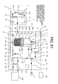
- FIG. 26 is a structural diagram of a storage type hot water supply system according to Embodiment 5 of the present invention.
- the storage type hot water supply system includes a hot water storage tank unit 1 having a hot water storage tank 2 for storing hot and cold water, a heat pump unit 3 as a heater for heating the hot and cold water in the hot water storage tank 2, and a hot water tap 4 used in the kitchen, the restroom, and the like.
- a heat pump refrigerant circuit of the heat pump unit 3 includes a compressor, a refrigerant-water heat exchanger as a condenser, an electronic expansion valve, and an evaporator of forced air-cooled type.
- An operation of one cycle is performed in which carbon dioxide as a natural refrigerant compressed in the compressor is subjected to heat radiation in the refrigerant-water heat exchanger, subjected to decompressive expansion in the electronic expansion valve, vaporized in the evaporator owing to atmospheric heat, and then flows into the compressor again.
- a low temperature water take-out pipe 9 connects the bottom of the hot water storage tank 2 and the heat pump unit 3 as a heater to each other. Further, a high temperature water returning pipe 10 connects the top of the hot water storage tank 2 and the heat pump unit 3 to each other.
- the high temperature water returning pipe 10 is provided with a heating temperature sensor 23 and a high temperature water inflow valve 6.
- Low temperature water (5°C, for example) is boiled up to obtain high temperature water (90°C, for example) through an intermediation of the refrigerant-water heat exchanger in the heat pump refrigerant circuit.
- a cylindrical water intake tube 38 which is extended in the substantially vertical direction and has a sealed bottom surface.
- multiple hot water temperature sensors 34 for detecting the temperature of the hot and cold water in the hot water storage tank 2 in the height direction (substantially vertical direction) of the hot water storage tank 2.
- five hot water temperature sensors 34a, 34b, 34c, 34d, and 34e are attached at predetermined intervals in the height direction of the hot water storage tank 2.
- a water flow pipe 27 is connected to the upper end portion of the water intake tube 38 as a water intake tube body.
- the other end portion of the water flow pipe 27 is connected to the first valve portion of a high temperature water mixing three-way valve 28.
- the second valve portion of the high temperature water mixing three-way valve 28 is connected to one end portion of a hot water outlet pipe 7.
- the other end portion of the hot water outlet pipe 7 is connected to the upper portion of the hot water storage tank 2, and the high temperature water in the hot water storage tank 2 flows out to the exterior through the hot water outlet pipe 7.
- the third valve portion of the high temperature water mixing three-way valve 28 is connected to one end portion of a first downstream valve pipe 5.
- a hot and cold water temperature sensor 29 for detecting a temperature of hot and cold water which flows through the first downstream valve pipe 5 is attached to the first downstream valve pipe 5.
- the other end portion of the first downstream valve pipe 5 is connected to the first valve portion of a low temperature water mixing three-way valve 30.
- the second valve portion of the low temperature water mixing three-way valve 30 is connected to a second downstream valve pipe 32.
- the hot water supply temperature sensor 33 is attached near the low temperature water mixing three-way valve 30 of the second downstream valve pipe 32, and the hot water tap 4 is attached downstream of the second downstream valve pipe 32.
- the third valve portion of the low temperature water mixing three-way valve 30 is connected to the hot water supply pipe 31.
- the hot water supply pipe 31 is coupled with a water supply pipe 8 which is connected to the bottom portion of the hot water storage tank.
- a pressure pump (not shown) is mounted to the water supply pipe 8, and low temperature water is pumped into the hot water storage tank 2 and also flows through the hot water supply pipe 31 with the driving of the pressure pump.
- the temperature of the low temperature water is detected with use of a supplied water temperature sensor 37 attached to the water supply pipe 8.
- FIG. 27 is a perspective view of a water intake tube of the storage type hot water supply system according to Embodiment 5 of the present invention. Further, FIG. 28 is a perspective view of the outer cylinder of the water intake tube illustrated in FIG. 27 , and FIG. 29 is a perspective view of the inner cylinder of the water intake tube illustrated in FIG. 27 . Still further, FIG. 30 is a sectional view of the water intake tube illustrated in FIG. 27 .
- the water intake tube 38 as a water intake tube body includes the cylindrical outer cylinder 25 and the cylindrical inner cylinder 26 provided inside the outer cylinder 25 and coaxially therewith.
- the inner cylinder 26 has, on the side surface thereof, a spiral inner cylinder communication hole 141 as an opening portion extended in the vertical direction and in the circumferential direction while forming an angle smaller than 360 degrees.
- the outer cylinder 25 has an outer cylinder communication hole 139 as an opening portion linearly extended in the vertical direction. Owing to the inner cylinder communication hole 141 and the outer cylinder communication hole 139 overlapped with each other, there is formed the water intake hole 12 of the water intake tube 38 is formed through which the hot and cold water is taken-in from the hot water storage tank.
- the upper portion of the inner cylinder 26 is provided with the upper communication hole 42, and the outer periphery thereof is covered with the upper communication portion 21.
- the leading end portion of the intermediate temperature water upper pipe 27 is passed through the side surface of the upper communication portion 21.
- the drive motor 35 is mounted to the top portion of the inner cylinder 26.
- the inner cylinder 26 is rotated in the circumferential direction through driving of the drive motor 35, and the rotational angle is controlled, whereby the position in the height direction (substantially vertical direction) of the water intake hole 12 can be continuously regulated.
- Hot and cold water is filled in the hot water storage tank 2, and the high temperature water 15, the intermediate temperature water 16, and low temperature water 17 are stored in the stated order from the top.
- the temperature of the high temperature water 15 is approximately 90°C which is obtained through heating in the heat pump unit 3
- the temperature of the low temperature water 17 is approximately 5°C which is obtained from the hot and cold water flowing through the water supply pipe 8.
- the intermediate temperature water 16 has a temperature gradient of approximately 5°C to 90°C due to thermal diffusion from the high temperature water 15.
- the temperature difference between the intermediate temperature water 16 and the high temperature water to be obtained is small when compared with the case of heating the low temperature water 17 to obtain the high temperature water. Accordingly, the COP of the heat pump unit 3 is lower.
- the hot water temperature sensors 34b, 34c, and 34d detect 90°C, 40°C, and 5°C, respectively, it can be determined that the intermediate temperature water exists near the height of the hot water temperature sensor 34c because the temperature detected by the hot water temperature sensor 34c is higher than 5°C and lower than 90°C. Further, when the multiple hot water temperature sensors 34 detect the temperature higher than 5°C and lower than 90°C, it may be determined that the intermediate temperature water exists at the position of one of the hot water temperature sensors 34, which indicates a temperature approximate to the required hot water supply temperature.
- the hot water temperature sensors 34c and 34d detect 90°C and 5°C, respectively, and when none of the other hot water temperature sensors 34 detects the temperature higher than 5°C and lower than 90°C, it may be determined that the intermediate temperature water exists at a midpoint of the hot water temperature sensors 34c and 34d between which the temperature difference is largest.
- the drive motor 35 is driven for rotating the inner cylinder 26 so as to move the water intake hole 12 of the water intake tube 38, which is formed of the outer cylinder communication hole 139 and the inner cylinder communication hole 141 overlapped with each other, to the position at which the intermediate temperature water 16 exists. Then, the intermediate temperature water 16 is immediately taken-in from the water intake hole 12, and the intermediate temperature water is taken out from the hot water storage tank 2 via the upper communication hole 42 of the inner cylinder 26 and the upper communication portion 21.
- the temperature of the hot and cold water taken out from the hot water storage tank 2 is controlled, with use of the drive motor 35 which is driven for rotating the inner cylinder 26 so as to continuously move the position of the water intake hole 12 of the water intake tube 38 in the height direction of the hot water storage tank 2, so as not to become lower than the required hot water supply temperature.
- the high temperature water 15, intermediate temperature water 16, and low temperature water 17 are stored in the stated order from the top to the bottom thereof.
- the drive motor 35 is driven for rotating the inner cylinder 26 so as to continuously change the position of the water intake hole 12 of the water intake tube 38 to the upper side in the hot water storage tank, and the temperature detected with use of the hot and cold water temperature sensor 29 is controlled so as to exceed the required hot water supply temperature.
- the drive motor 35 is driven for rotating the inner cylinder 26 so as to continuously change the position of the water intake hole 12 of the water intake tube 38 to the lower side in the hot water storage tank, and the temperature detected with use of the hot and cold water temperature sensor 29 is controlled to be approximate to the required hot water supply temperature, and so as not to be lower than the required hot water supply temperature.
- the position in the height direction of the water intake hole 12 can be continuously changed, and hence the temperature of the hot and cold water taken out from the water intake tube 38 can be finely controlled.
- the hot and cold water passing through the first downstream valve pipe 5 and the low temperature water supplied from the water supply pipe 8 for hot water supply are mixed with each other.
- the mixed hot and cold water is supplied as water for hot water supply via the second downstream valve pipe 32 and the hot water tap 4.
- control of the required hot water supply temperature is conducted through changing the mixing ratio between the hot and cold water and the low temperature water with use of the low temperature water mixing three-way valve 30 activated based on the temperature which is detected with use of the hot water supply temperature sensor 33.
- the low temperature water 17 is supplied from the lower side of the hot water storage tank 2 through the water supply pipe 8, to the amount of which corresponds to an amount of the hot and cold water taken out from the hot water storage tank 2.
- the predetermined hot water temperature sensor 34 (hot water temperature sensor 34b, for example) becomes lower than 90°C, and it is determined that the amount of the high temperature water 15 in the hot water storage tank 2 is decreased, the low temperature water 17 is taken out via the low temperature water take-out pipe 9 from the lower side of the hot water storage tank 2.
- the high temperature water heated in the heat pump unit 3 is returned from the upper side of the hot water storage tank 2 via the high temperature water returning pipe 10 and the high temperature water inflow valve 6.
- carbon dioxide as a natural refrigerant is used in the heat pump unit 3.
- low temperature water is heated to have high temperature of approximately 90°C.
- the low temperature water is heated to have the high temperature with high energy efficiency.
- the intermediate temperature water 16 generated in the hot water storage tank 2 can be immediately taken out.
- the intermediate temperature water 16 which exists in the hot water storage tank 2 can be decreased within a short period of time, and the proportion of the high temperature water 15 is not reduced despite the increase in proportion of the intermediate temperature water 16, whereby the lack of the high temperature water 15 in the hot water storage tank 2 is reduced.
- a high COP is secured in the heat pump unit 3.
- the position of the water intake hole 12 of the water intake tube 38 is continuously regulated in the height direction of the hot water storage tank 2 based on the temperature of the hot and cold water in the hot water storage tank 2 detected with use of the hot water temperature sensor 34 and the temperature of the hot and cold water taken out to the exterior of the hot water storage tank 2 detected with use of the hot and cold water temperature sensor 29.
- the position of the water intake hole 12 of the water intake tube 38 may be continuously regulated in the height direction of the hot water storage tank 2 based also on one of the temperature of the hot and cold water in the hot water storage tank 2 detected with use of the hot water temperature sensor 34 and the temperature of the hot and cold water taken out to the exterior of the hot water storage tank 2 detected with use of the hot and cold water temperature sensor 29.
- the temperature of the wall surface of the hot water storage tank 2 detected with use of the hot water temperature sensor 34 mounted to the outer peripheral surface (side surface) of the hot water storage tank 2 is defined as a temperature of the hot and cold water in the hot water storage tank 2.
- the hot water temperature sensor 34 may be mounted to the inner peripheral surface (side surface) of the hot water storage tank 2 so as to directly detect the temperature of the hot and cold water in the hot water storage tank 2.
- the temperature of hot and cold water taken out from the hot water storage tank 2 with use of the water intake tube 38 is set to be higher than the required hot water supply temperature.
- the temperature of the hot and cold water taken out through the water intake tube 38 can be risen to a temperature higher than the required hot water supply temperature, owing to the high temperature water mixing three-way valve 28 activated so as to increase the amount of the high temperature water 15 through the hot water outlet pipe 7. Therefore, almost all the intermediate temperature water 16 in the hot water storage tank 2 can be taken out for being used as water for hot water supply, the lack of the high temperature water 15 in the hot water storage tank 2 is further overcome, and a higher COP is secured in the heat pump unit 3.
- control of each of the flow rate ratios between the hot and cold water taken out from the hot water storage tank 2 and the high temperature water or the low temperature water is described which is conducted with use of the three-way valves including the high temperature water mixing three-way valve 28 or the low temperature water mixing three-way valve 30.
- two valves may be used instead of the three-way valve so as to control the flow rate ratios.
- the inner cylinder 26 is rotated with use of the drive motor 35 so as to relatively move the inner cylinder 26 and the outer cylinder 25 to each other, whereby the position of the water intake hole 12 of the water intake tube 38, which is formed of the inner cylinder communication hole 141 and the outer cylinder communication hole 139 overlapped with each other, is continuously changed in the height direction of the hot water storage tank 2.
- the outer cylinder 25 may be rotated with use of the drive motor 35 so as to relatively move the inner cylinder 26 and the outer cylinder 25 to each other, whereby the position of the water intake hole 12 of the water intake tube 38, which is formed of the inner cylinder communication hole 141 and the outer cylinder communication hole 139 overlapped with each other, is continuously changed in the height direction of the hot water storage tank 2.
- the inner cylinder communication hole 141 and the outer cylinder communication hole 139 may be formed correspondingly to the height at which the intermediate temperature water exists, whereby the position of the water intake hole 12 of the water intake tube 38 is continuously changed in the height direction of the hot water storage tank 2 only within the range over which the intermediate temperature water exists.
- FIGS. 31 to 33 are perspective views each illustrating another mode of the water intake tube of the storage type hot water supply system according to Embodiment 5 of the present invention.
- the spiral inner cylinder communication hole 141 extended in the vertical direction and in the circumferential direction is formed in the side surface of the inner cylinder 26, and the outer cylinder communication hole 139 linearly extended in the vertical direction is formed in the side surface of the outer cylinder 25.
- ribs 143 may be provided for partitioning the outer cylinder communication hole 139 or the inner cylinder communication hole 141 in the upper and lower direction.
- the inner cylinder 26 and the outer cylinder 25 are moved relatively to each other, whereby the position of the water intake hole 12 of the water intake tube 38, which is formed of the inner cylinder communication hole 141 and the outer cylinder communication hole 139 overlapped with each other, is continuously changed in the height direction of the hot water storage tank 2 even over a small distance.
- the strength of the outer cylinder 25 or the inner cylinder 26 can be enhanced with the provision of the ribs 143 for partitioning the outer cylinder communication hole 139 or the inner cylinder communication hole 141 in the upper and lower direction.
- the five hot water temperature sensors 34a, 34b, 34c, 34d, and 34e are provided on the side surface of the hot water storage tank 2.
- the position and temperature of the intermediate temperature water 16 can be more accurately detected.
- the hot water temperature sensors 34 may be arranged at equal intervals in the height direction, or may be arranged at random in the height direction.
- the water intake tube 38 may be extended to the bottom portion of the hot water storage tank 2 so as to be supported at the bottom portion of the hot water storage tank 2. Further, the bottom portion of the hot water storage tank 2 may be passed through so as to support the water intake tube 38 outside the hot water storage tank 2.
- a water intake tube of a storage type hot water supply system according to Embodiment 6 is different from the water intake tube according to Embodiment 5 in the point of being provided with multiple water intake holes 12 at different heights.
- the other structure and functions are the same as those of the storage type hot water supply system and the water intake tube according to Embodiment 5.
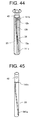
- FIG. 34 is a perspective view of the water intake tube of the storage type hot water supply system according to Embodiment 6 of the present invention. Further, FIG. 35 is a perspective view of the outer cylinder of the water intake tube illustrated in FIG. 34 , and FIG. 36 is a perspective view of the inner cylinder of the water intake tube illustrated in FIG. 34 .
- the inner cylinder 26 has, on the side surface thereof, a single spiral inner cylinder communication hole 141 extended in the vertical direction and in the circumferential direction
- the outer cylinder 25 has two outer cylinder communication holes 139a and 139b as opening portions linearly extended in the vertical direction and arranged in the circumferential direction.
- the inner cylinder 26 is rotated in the circumferential direction through driving of the drive motor 35 so as to continuously change, in the height direction of the hot water storage tank 2, the position of the water intake hole 12a which is formed of the inner cylinder communication hole 141 and the outer cylinder communication hole 139a overlapped with each other, and the position of the water intake hole 12b which is formed of the inner cylinder communication hole 141 and the outer cylinder communication hole 139b overlapped with each other, the water intake holes 12a and 12b being provided to the water intake tube 38.
- the water intake hole 12a is positioned lower than the water intake hole 12b.
- the drive motor 35 is controlled to move the water intake hole 12a to the position corresponding to the height of the hot water temperature sensor 34d.
- the intermediate temperature water 16 is taken-in from the water intake hole 12a, and the hot and cold water of a temperature higher than that of the hot and cold water taken-in from the water intake hole 12a is taken-in from the water intake hole 12b positioned higher than the water intake hole 12a. Then, the hot and cold water is taken out from the hot water storage tank 2 via the upper communication hole 42 of the inner cylinder 26 and the upper communication portion 21.
- the position of the water intake hole 12a and the position of water intake hole 12b are continuously changed in the height direction of the hot water storage tank 2 and controlled with use of the drive motor 35 such that the temperature of the hot and cold water does not become lower than a required hot water supply temperature.
- the hot and cold water thus taken out reaches the low temperature water mixing three-way valve 30 via the water flow pipe 27 and the high temperature water mixing three-way valve 28.
- the hot and cold water thus taken out and the low temperature water supplied from the water supply pipe 8 for hot water supply are mixed with each other.
- the mixed hot and cold water is supplied as water for hot water supply via the second downstream valve pipe 32 and the hot water tap 4.
- control of the required hot water supply temperature is conducted through changing the mixing ratio between the hot and cold water and the low temperature water with use of the low temperature water mixing three-way valve 30 activated based on the temperature which is detected with use of the hot water supply temperature sensor 33.
- FIG. 37 is a graph showing a temporal change of the temperature of hot and cold water, which is detected with use of the hot water temperature sensor of the storage type hot water supply system according to Embodiment 6 of the present invention.
- the intermediate temperature water 16 and the hot and cold water of a temperature higher than that of the intermediate temperature water 16 taken out from the water intake hole 12a are taken out from the water intake hole 12a and the water intake hole 12b, respectively.
- the temporal change in the temperature of the hot water taken out with use of the water intake tube 38 can be further reduced. Therefore, it is possible to further facilitate the temperature control for approximating the temperature to the required hot water supply temperature, the temperature control being performed with use of the low temperature water mixing three-way valve 30.
- FIG. 38 is a perspective view illustrating another mode of a water intake tube of the storage type hot water supply system according to Embodiment 6 of the present invention. Further, FIG. 39 is a perspective view of the outer cylinder of the water intake tube illustrated in FIG. 38 , and FIG. 40 is a perspective view of the inner cylinder of the water intake tube of the storage type hot water supply system illustrated in FIG. 38 .
- two spiral inner cylinder communication holes 141 a and 141 b as opening portions extended in the vertical direction and in the circumferential direction may be formed at different heights, and on the side surface of the outer cylinder 25, a single spiral outer cylinder communication hole 139 extended in the vertical direction and in the circumferential direction may be formed.
- the inner cylinder 26 is rotated in the circumferential direction through driving of the drive motor 35 so as to continuously change, in the height direction of the hot water storage tank 2, the position of the water intake hole 12a which is formed of the inner cylinder communication hole 141a and the outer cylinder communication hole 139 overlapped with each other, and the position of the water intake hole 12b which is formed of the inner cylinder communication hole 141 b and the outer cylinder communication hole 139 overlapped with each other, the water intake holes 12a and 12b being provided to the water intake tube 38.
- the number and the configuration are arbitrary of the inner cylinder communication holes 141 as opening portions formed in the inner cylinder 26 and the outer cylinder communication hole 139 as opening portion formed in the outer cylinder 25. It suffices that the inner cylinder 26 and the outer cylinder 25 are moved relatively to each other for overlapping each of the inner cylinder communication holes 141 and the outer cylinder communication hole 139 each other so as to form the multiple water intake holes 12, whereby the positions of the multiple water intake holes 12 can be continuously changed in the height direction of the hot water storage tank 2.
- the multiple outer cylinder communication holes 139 or the multiple inner cylinder communication holes 141 are provided, whereby the multiple water intake holes are formed at different heights.
- a water intake tube of a storage type hot water supply system according to Embodiment 7 is different from the water intake tube according to Embodiment 5 in the point of having a circumferential communication hole extended in the circumferential direction above a spiral outer cylinder communication hole and a spiral inner cylinder communication hole.
- the other structure and functions are the same as those of the storage type hot water supply system and the water intake tube according to Embodiment 5.
- FIG. 41 is a perspective view of the water intake tube of the storage type hot water supply system according to Embodiment 7 of the present invention. Further, FIG. 42 is a perspective view of the outer cylinder of the water intake tube of the storage type hot water supply system according to Embodiment 7 of the present invention, and FIG. 43 is a perspective view of the inner cylinder of the water intake tube of the storage type hot water supply system according to Embodiment 7 of the present invention.
- a spiral inner cylinder communication hole 141 a as an opening portion extended in the vertical direction and in the circumferential direction is formed on the side surface of the inner cylinder 26 .
- an inner circumferential cylinder communication hole 141 b as an opening portion extended in the circumferential direction is formed above the inner cylinder communication hole 141 a to be coupled to the inner cylinder communication hole 141a at the position corresponding to the upper portion of the hot water storage tank 2.
- the outer cylinder communication hole 139 as an opening portion linearly extended in the vertical direction is formed.
- the inner cylinder 26 is rotated in the circumferential direction through driving of the drive motor 35, and the rotational angle is controlled, whereby the position of the water intake hole 12a of the water intake tube 38, which is formed of the spiral inner cylinder communication hole 141a and the outer cylinder communication hole 139 overlapped with each other, can be continuously changed in the height direction of the hot water storage tank 2.
- the height of the water intake hole 12b of the water intake tube 38 is fixed, which is formed of the inner circumferential cylinder communication hole 141b and the outer cylinder communication hole 139 overlapped with each other.
- the drive motor 35 is controlled to move the water intake hole 12a to the position corresponding to the height of the hot water temperature sensor 34c.
- the intermediate temperature water 16 is taken-in from the water intake hole 12a, and the high temperature water 15 is taken-in from the water intake hole 12b positioned at the upper portion of the hot water storage tank 2.
- the hot and cold water is taken out from the hot water storage tank 2 via the upper communication hole 42 of the inner cylinder 26 and the upper communication portion 21.
- the temperature of the hot and cold water taken out from the hot water storage tank 2 is controlled, with use of the drive motor 35 which is controlled to continuously move the position of the water intake hole 12a in the height direction of the hot water storage tank, so as not to become lower than the required hot water supply temperature.
- the hot and cold water thus taken out reaches the low temperature water mixing three-way valve 30 via the water flow pipe 27 and the high temperature water mixing three-way valve 28.
- the hot and cold water thus taken out and the low temperature water supplied from the water supply pipe 8 for hot water supply are mixed with each other.
- the mixed hot and cold water is supplied as water for hot water supply via the second downstream valve pipe 32 and the hot water tap 4.
- control of the required hot water supply temperature is conducted through changing the mixing ratio between the hot and cold water and the low temperature water with use of the low temperature water mixing three-way valve 30 activated based on the temperature which is detected with use of the hot water supply temperature sensor 33.
- the intermediate temperature water 16 and the high temperature water 15 are taken out from the water intake hole 12a and the water intake hole 12b, respectively.
- the temporal change in the temperature of the hot water taken out with use of the water intake tube 38 can be further reduced. Therefore, it is possible to further facilitate the temperature control for approximating the temperature to the required hot water supply temperature, the temperature control being performed with use of the low temperature water mixing three-way valve 30.
- FIG. 44 is a perspective view illustrating another mode of the water intake tube of the storage type hot water supply system according to Embodiment 7 of the present invention
- FIG. 45 is a perspective view illustrating another mode of the inner cylinder of the water intake tube of the storage type hot water supply system according to Embodiment 7 of the present invention.
- the spiral inner cylinder communication hole 141 a and the inner circumferential cylinder communication hole 141b may be separately formed in the side surface of the inner cylinder 26 instead of being coupled to each other.
- the number and the configuration are arbitrary of the inner cylinder communication hole 141a as an opening portion formed on the side surface of the inner cylinder 26 and the outer cylinder communication hole 139 as an opening portion formed in the outer cylinder 25. It suffices that the inner cylinder 26 and the outer cylinder 25 are moved relatively to each other for overlapping the inner cylinder communication hole 141a, the inner circumferential cylinder communication hole 141b, and the outer cylinder communication hole 139 each other so as to form the multiple water intake holes 12 such that the high temperature water can be taken out of at least one of the water intake holes 12, whereby the positions of the multiple water intake holes 12 can be continuously changed in the height direction of the hot water storage tank 2.
- the high temperature water 15 can be taken out from the water intake hole 12b, and hence when the position of the water intake hole 12a can be regulated with use of the drive motor such that the temperature of the hot and cold water detected with use of the hot and cold water temperature sensor 29 becomes equal to or higher than the required hot water supply temperature, it is possible to omit the hot water outlet pipe 7 and the high temperature water mixing three-way valve 28, to thereby achieve simplification of the storage type hot water supply system and cost reduction.
- the spiral inner cylinder communication hole 141a is formed in the side surface of the inner cylinder 26, and the inner circumferential cylinder communication hole 141 b extended in the circumferential direction is formed above the spiral inner cylinder communication hole 141a, and the outer cylinder communication hole 139 linear in the vertical direction is formed in the side surface of the outer cylinder 25.
- a water intake tube of a storage type hot water supply system according to Embodiment 8 is different from the water intake tube according to Embodiment 9 in the point of having a circumferential communication hole extended in the circumferential direction below a spiral outer cylinder communication hole and a spiral inner cylinder communication hole,
- the other structure and functions are the same as those of the storage type hot water supply system and the water intake tube according to Embodiment 9.
- FIG. 46 is a perspective view of the water intake tube of the storage type hot water supply system according to Embodiment 8 of the present invention. Further, FIG. 47 is a perspective view of the outer cylinder of the water intake tube of the storage type hot water supply system according to Embodiment 8 of the present invention, and FIG. 48 is a perspective view of the inner cylinder of the water intake tube of the storage type hot water supply system according to Embodiment 8 of the present invention.
- a spiral inner cylinder communication hole 141 a as an opening portion extended in the vertical direction and in the circumferential direction is formed on the side surface of the inner cylinder 26.
- an inner circumferential cylinder communication hole 141c as an opening portion extended in the circumferential direction is formed to be coupled to the inner cylinder communication hole 141 a at the position corresponding to the lower portion of the hot water storage tank 2.
- the outer cylinder communication hole 139 as an opening portion linearly extended in the vertical direction is formed on the side surface of the outer cylinder 25.
- the inner cylinder 26 is rotated in the circumferential direction through driving of the drive motor 35, and the rotational angle is controlled, whereby the position of the water intake hole 12a of the water intake tube 38, which is formed of the spiral inner cylinder communication hole 141a and the outer cylinder communication hole 139 overlapped with each other, can be continuously changed in the height direction of the hot water storage tank 2.
- the height of the water intake hole 12c of the water intake tube 38 is fixed, which is formed of the inner circumferential cylinder communication hole 141c and the outer cylinder communication hole 139 overlapped with each other.
- the drive motor 35 is controlled to move the water intake hole 12a to the position corresponding to the height of the hot water temperature sensor 34c.
- the intermediate temperature water 16 is taken-in from the water intake hole 12a, and the low temperature water 17 is taken-in from the water intake hole 12c positioned at the lower portion of the hot water storage tank 2.
- the hot and cold water is taken out from the hot water storage tank 2 via the upper communication hole 42 of the inner cylinder 26 and the upper communication portion 21.
- the temperature of the hot and cold water taken out from the hot water storage tank 2 is controlled so as not to become lower than the required hot water supply temperature, with use of the drive motor 35 which is controlled to continuously move the position of the water intake hole 12a in the height direction of the hot water storage tank, by using the high temperature water mixing three-way valve 28 for controlling the amount of the hot and cold water passing the water flow pipe 27 and of the high temperature water passing the hot water outlet pipe 7.
- the hot and cold water controlled in the high temperature water mixing three-way valve 28 reaches the low temperature water mixing three-way valve 30 via the first downstream valve pipe 5.
- the low temperature water mixing three-way valve 30 the hot and cold water taken out and the low temperature water supplied from the water supply pipe 8 for hot water supply are mixed with each other.
- the mixed hot and cold water is supplied as water for hot water supply via the second downstream valve pipe 32 and the hot water tap 4.
- control of the required hot water supply temperature is conducted through changing the mixing ratio between the hot and cold water and the low temperature water with use of the low temperature water mixing three-way valve 30 activated based on the temperature which is detected with use of the hot water supply temperature sensor 33.
- the intermediate temperature water 16 and the low temperature water 17 are taken out from the water intake hole 12a and the water intake hole 12c, respectively, so as to be mixed, with use of the high temperature water mixing three-way valve 28, with the high temperature water 15 taken out through the hot water outlet pipe 7.
- the temperature of the hot and cold water thus mixed is controlled to be approximate to the required hot water supply temperature. Therefore, it is possible to further facilitate the temperature control for approximating the temperature to the required hot water supply temperature, the temperature control being performed with use of the low temperature water mixing three-way valve 30.
- FIG. 49 is a perspective view illustrating another mode of the water intake tube of the storage type hot water supply system according to Embodiment 8 of the present invention
- FIG. 50 is a perspective view illustrating another mode of the inner cylinder of the water intake tube of the storage type hot water supply system according to Embodiment 8 of the present invention.
- the spiral inner cylinder communication hole 141a and the inner circumferential cylinder communication hole 141c may be separately formed in the side surface of the inner cylinder 26 instead of being coupled to each other.
- the number and the configuration are arbitrary of the inner cylinder communication hole 141 formed in the inner cylinder 26 and the outer cylinder communication hole 139 formed in the outer cylinder 25. It suffices that the inner cylinder 26 and the outer cylinder 25 are moved relatively to each other for overlapping the inner cylinder communication hole 141a, the inner circumferential cylinder communication hole 141c, and the outer cylinder communication hole 139 each other so as to form the multiple water intake holes 12 such that the low temperature water can be taken out of at least one of the water intake holes 12, whereby the positions of the multiple water intake holes 12 can be continuously changed in the height direction of the hot water storage tank 2.
- the low temperature water 17 can be taken out from the water intake hole 12c, and hence when the temperature of the hot and cold water detected with use of the hot and cold water temperature sensor 29 can be controlled to become equal to the required hot water supply temperature, it is possible to omit the water supply pipe 31 for hot water supply and the low temperature water mixing three-way valve 30, to thereby achieve simplification of the storage type hot water supply system and cost reduction.
- a water intake tube of a storage type hot water supply system according to Embodiment 9 is different from the water intake tube according to Embodiment 9 in the point that circumferential communication holes extended in the circumferential direction are provided above and below a spiral outer cylinder communication hole or a spiral inner cylinder communication hole, an at least one of the outer cylinder and the inner cylinder is moved in the vertical direction.
- the other structure and functions are the same as those of the storage type hot water supply system and the water intake tube according to Embodiment 9.
- FIG. 51 is a structural diagram of the water intake tube of the storage type hot water supply system according to Embodiment 9 of the present invention
- FIG. 52 is a perspective view of the water intake tube of the storage type hot water supply system according to Embodiment 9 of the present invention
- FIG. 53 is a perspective view of the outer cylinder of the water intake tube of the storage type hot water supply system according to Embodiment 9 of the present invention
- FIG. 54 is a perspective view of the inner cylinder of the water intake tube of the storage type hot water supply system according to Embodiment 9 of the present invention.
- a spiral inner cylinder communication hole 141a as an opening portion extended in the vertical direction and in the circumferential direction is formed on the side surface of the inner cylinder 26.
- inner circumferential cylinder communication holes 141b and 141c as opening portions extending in the circumferential direction are formed above and below the inner cylinder communication hole 141a.
- the inner cylinder communication hole 141a and the inner circumferential cylinder communication hole 141 b are coupled to each other, and the inner cylinder communication hole 141a and the inner circumferential cylinder communication hole 141c are coupled to each other.
- the outer cylinder communication hole 139 as an opening portion linearly extended in the vertical direction is formed on the side surface of the outer cylinder 25, the outer cylinder communication hole 139 having a height L (distance in the vertical direction) smaller than a height H (distance in the vertical direction) measured from the lower end of the inner circumferential cylinder communication hole 141b to the upper end of the inner circumferential cylinder communication hole 141c.
- L distance in the vertical direction
- H distance in the vertical direction
- the water intake tube 38 as a water intake tube body has a sliding mechanism capable of moving the inner cylinder 26 in the vertical direction. With use of the inner cylinder 26 moved downward in the vertical direction, it is possible to take out only the intermediate temperature water, the intermediate temperature water and the high temperature water, or the intermediate temperature water and the low temperature water.
- FIG. 55 is a perspective view illustrating a case where the inner cylinder is moved downward in the vertical direction in a water intake tube of a storage type hot water supply system according to Embodiment 9 of the present invention.
- FIG. 56 is a perspective view illustrating a case where the inner cylinder is moved upward in the vertical direction in a water intake tube of a storage type hot water supply system according to Embodiment 9 of the present invention.
- the drive motor 35 is controlled to move the water intake hole 12a to the position corresponding to the height of the hot water temperature sensor 34c.
- the intermediate temperature water 16 is taken-in from the water intake hole 12a, and then the hot and cold water is taken out from the hot water storage tank 2 via the upper communication hole 42 of the inner cylinder 26 and the upper communication portion 21.
- the inner cylinder 26 is moved downward in the vertical direction with use of the sliding mechanism such that the high temperature water 15 is take out from the water intake hole 12b so as to be mixed with the hot and cold water taken out from the water intake hole 12a.
- the inner cylinder 26 is regulated in the vertical direction so as to set the temperature of the hot and cold water detected with use of the hot and cold water temperature sensor 29 to be equal to the required hot water supply temperature, to thereby determine the appropriate opening area of the water intake hole 12b.
- the inner cylinder 26 is moved upward in the vertical direction with use of the sliding mechanism such that the low temperature water 17 is taken out from the water intake hole 12c so as to be mixed with the hot and cold water taken out from the water intake hole 12a.
- the inner cylinder 26 is regulated in the vertical direction so as to set the temperature of the hot and cold water detected with use of the hot and cold water temperature sensor 29 to be equal to the required hot water supply temperature, to thereby determine the appropriate opening area of the water intake hole 12c.
- the hot and cold water thus taken out flows through the water flow pipe 27 so as to be supplied as water for hot water supply via the hot water tap 4.
- the inner cylinder 26 is moved downward in the vertical direction so as to change the length T over which the inner circumferential cylinder communication hole 141b and the outer cylinder communication hole 139 are overlapped with each other.
- the opening area of the water intake hole 12b is a product of the length T and a width W of the outer cylinder communication hole.
- the inner cylinder 26 is moved upward in the vertical direction so as to change a length B over which the inner circumferential cylinder communication hole 141c and the outer cylinder communication hole 139 are overlapped with each other.
- the opening area of the water intake hole 12c is a product of the length B and the width W of the outer cylinder communication hole.
- the water intake tube 38 of the storage type hot water supply system it is possible to take out the high temperature water 15 from the water intake hole 12b while taking out the intermediate temperature water 16 from the water intake hole 12a. Further, it is also possible to take out the low temperature water 17 from the water intake hole 12c while taking out the intermediate temperature water 16 from the water intake hole 12a. In addition, it is possible to control the flow rate of the high temperature water 15 taken out from the water intake hole 12b, or the flow rate of the low temperature water 17 taken out from the water intake hole 12c.
- the hot and cold water of a temperature equal to the required hot water supply temperature can be taken out with use of only the water intake tube 38, whereby the high temperature water mixing three-way valve 28 and the low temperature water mixing three-way valve 30 can be omitted so as to simplify the storage type hot water supply system and to achieve cost reduction.
- the spiral inner cylinder communication hole 141a is formed in the side surface of the inner cylinder 26, and the inner circumferential cylinder communication holes 141b and 141 c extended in the circumferential direction are formed above and below the inner cylinder communication hole 141a, and the outer cylinder communication hole 139 linear in the vertical direction is formed in the side surface of the outer cylinder 25.
- FIG. 57 is a structural diagram of a storage type hot water supply system according to Embodiment 10 of the present invention.
- the storage type hot water supply system includes a hot water storage tank unit 1 having a hot water storage tank 2, a heat pump unit 3 as a heater for heating the hot and cold water in the hot water storage tank 2, a hot water tap 4 used in the kitchen, the restroom, and the like, and a heat exchanger 218 for performing, heat exchange of high temperature water fed from the hot water storage tank 2 with a heating terminal 206 including a floor heating system, a bath, and a bathroom dryer. Further, in the hot water storage tank 2, a cylindrical intermediate temperature water passing pipe 238 is provided so as to be extended in the upper and lower direction (substantially vertical direction). Note that, in the case of using the floor heating system or the like the heating terminal 206 itself may function as the heat exchanger 218.
- a heat pump refrigerant circuit 215 of the heat pump unit 3 includes a compressor 211, a refrigerant-water heat exchanger 212 as a condenser, an electronic expansion valve 213, and an evaporator 214 of forced air-cooled type.
- An operation of one cycle is performed in which carbon dioxide as a natural refrigerant compressed in the compressor 211 is subjected to heat radiation in the refrigerant-water heat exchanger 212 so as to be liquidized, subjected to decompressive expansion in the electronic expansion valve 213, vaporized in the evaporator 214 owing to atmospheric heat, and then flows into the compressor 211 again.
- low temperature water (5°C, for example) is heated to obtain high temperature water (90°C, for example) through an intermediation of the refrigerant-water heat exchanger 212 in the heat pump refrigerant circuit 215.
- carbon dioxide as a natural refrigerant is compressed in the supercritical state with use of the refrigerant-water heat exchanger 212, and hence the hot and cold water can be efficiently heated to have high temperature.
- FIG. 58 is a perspective view of an outer cylinder 80 of the intermediate temperature water passing pipe 238 illustrated in FIG. 57
- FIG. 59 is a perspective view of an inner cylinder 81 of the intermediate temperature water passing pipe 238 illustrated in FIG. 57
- FIG. 60 is a perspective view illustrating the intermediate temperature water passing pipe 238 as a whole of FIG. 57
- FIG. 61 is a sectional view of the intermediate temperature water passing pipe 238.
- the intermediate temperature water passing pipe 238 as a pipe body includes the outer cylinder 80 and the inner cylinder 81 provided inside the outer cylinder 80 and slidably in the circumferential direction.
- the outer cylinder 80 is provided with outer cylinder holes 239a, 239b, 239c, 239d, and 239e as opening portions having the same diameter and formed at intervals in the upper and lower direction and the circumferential direction, that is, at different positions in the upper and lower direction and the circumferential direction.
- the inner cylinder 81 is provided with inner cylinder holes 241a, 241b, 241c, 241d, and 241e as opening positions having the same diameter and formed at intervals in the upper and lower direction and the circumferential direction, that is, at different positions in the upper and lower direction and the circumferential direction.
- the upper portion of the inner cylinder 81 is provided with the upper communication hole 42. Further, the upper portion of the inner cylinder 81 is covered with the upper communication portion 21. The leading end portion of an upper intermediate-temperature-water passing pipe 227 is passed through the side surface of the upper communication portion 21. Further, the drive motor 35 is mounted to the top portion of the inner cylinder 81. The inner cylinder 81 is rotated in the circumferential direction through driving of the drive motor 35.
- a small diameter portion at the lower portion of the inner cylinder 81 is provided with a lower communication hole 243. Further, the small diameter portion is covered with a lower communication portion 225. The leading end portion of a lower intermediate-temperature-water passing pipe 220 is passed through the side surface of the lower communication portion 225.
- the inner cylinder 81 rotated through driving of the drive motor 35, it is possible to form at least one communication portion with use of the outer cylinder holes 239a, 239b, 239c, 239d, and 239e formed in the outer cylinder 80 and the inner cylinder holes 241a, 241b, 241c, 241d, and 241e formed in the inner cylinder 81 respectively overlapped with each other.
- the height (position in the vertical direction) of the communication portion can be immediately changed though which hot and cold water flows.
- the outer cylinder hole 239c formed in the outer cylinder 80 and the inner cylinder hole 241 c formed in the inner cylinder 81 are overlapped with each other at the height corresponding to the outer cylinder hole 239c of the outer cylinder 80, to thereby form the communication portion.
- the inner cylinder 81 and the outer cylinder 80 function, at a boiling-up operation, as a pipe body for heating through which the hot and cold water heated in the heat pump unit 3 flows thereinto from the upper portion and flows out from the communication portion, and at a heating operation, as a pipe body for space heating through which the hot and cold water subjected to heat exchange in the heat exchanger 218 flows thereinto from the lower portion and flows out from the communication portion.
- the inner cylinder 81 and the outer cylinder 80 function, at a hot water supply operation, as a pipe body through which the hot and cold water flows thereinto from the communication portion and flows out from the upper portion.
- the intermediate temperature water passing pipe 238 may be used as a pipe body for heating or a pipe body for space heating so as to allow the hot and cold water to flow into the hot water storage tank at an arbitrary height therein. Further, at the hot water supply operation, the intermediate temperature water passing pipe 238 may be used as a pipe body for hot water supply so as to take out the hot and cold water at the arbitrary height in the hot water storage tank 2.
- the hot water temperature sensor 34 is provided for detecting the temperature of hot and cold water in the hot water storage tank 2.
- five hot water temperature sensors 34a, 34b, 34c, 34d, and 34e are attached at predetermined intervals in the upper and lower direction.
- the hot water supply temperature sensor 33 for detecting the temperature of the hot and cold water is attached to a pipe 232 provided downstream of the valve for mixing hot water to be supplied, the hot and cold water flowing from the hot water storage tank 2 to the hot water tap 4 through the upper intermediate-temperature-water passing pipe 227, a pipe 48 provided downstream of the valve for mixing intermediate temperature water, and the pipe 232 provided downstream of the valve for mixing hot water to be supplied.
- a heating temperature sensor 23 for detecting the boiling-up temperature of the hot and cold water heated in the heat pump unit 3 is attached to the high temperature water returning pipe 10.
- a space-heating temperature sensor 240 for detecting the temperature of the hot and cold water subjected to heat exchange in the heat exchanger 218 is attached to the lower intermediate-temperature-water passing pipe 220.
- the operation in the storage type hot water supply system includes the hot water supply operation for supplying hot water from the hot water tap 4, the boiling-up operation for boiling hot water with use of the heat pump unit 3, and the heating operation for performing floor heating and additional heating of the bath with use of the heating terminal 206.
- FIG. 62 is an operational view illustrating a case where the storage type hot water supply system performs only the hot water supply operation.
- the hot and cold water is stored in the temperature distribution having a temperature gradient in the upper and lower direction.
- high temperature water 45, intermediate temperature water 46, and low temperature water 47 are filled in the stated order from the top.
- the temperature of the high temperature water 45 is 90°C
- the temperature of the low temperature water 47 is 5°C.
- the temperature of the intermediate temperature water 46 has a temperature gradient between the high temperature water and the low temperature water.
- the intermediate temperature water 46 cannot be used as a heat source for the heating operation because of low temperature therefor. Further, the intermediate temperature water 46 has a little temperature difference and low energy consumption efficiency even when being heated in the heat pump unit 3, and hence it is required that the intermediate temperature water 46 be used for hot water supply with priority.
- the height at which the intermediate temperature water 46 exists can be observed based on the temperature detected with use of the hot water temperature sensors 34a, 34b, 34c, 34d, and 34e provided on the side surface of the hot water storage tank 2. Simultaneously, the temperature of the intermediate temperature water 46 and the required hot water supply temperature are compared with each other.
- Embodiment 10 there is described the case where the five hot water temperature sensors 34a, 34b, 34c, 34d, and 34e are provided. However, with the provision of more hot water temperature sensors 34a, 34b, 34c, 34d, and 34e, the height at which the intermediate temperature water 46 exists and temperature thereof can be more accurately detected.
- the hot water temperature sensors 34a, 34b, 34c, 34d, and 34e are mounted in the central portion of the hot water storage tank 2, where the intermediate temperature water is likely to be distributed, at intervals each of which is equal to or smaller than 100 mm, the length of interval being determined with reference to the layer thickness of approximately 100 mm of the main intermediate temperature water. As a result, the detection accuracy for the height at which the intermediate temperature water 46 exists and temperature thereof is increased.
- the hot water temperature sensor 34 may be provided on the inner peripheral surface of the hot water storage tank 2 so as to directly detect the temperature of the hot and cold water in the hot water storage tank 2.
- the hot water temperature sensors 34b, 34c, and 34d detect 90°C, 40°C, and 5°C, respectively, it can be determined that the intermediate temperature water exists near the height of the hot water temperature sensor 34c because the temperature detected by the hot water temperature sensor 34c is higher than 5°C and lower than 90°C. Further, when the multiple hot water temperature sensors 34 detect the temperature higher than 5°C and lower than 90°C, it may be determined that the intermediate temperature water exists at the position of one of the hot water temperature sensors 34, which indicates a temperature approximate to the required hot water supply temperature.
- the hot water temperature sensors 34c and 34d detect 90°C and 5°C, respectively, and when none of the other hot water temperature sensors 34 detects the temperature higher than 5°C and lower than 90°C, it may be determined that the intermediate temperature water exists at a midpoint of the hot water temperature sensors 34c and 34d between which the temperature difference is largest.
- the drive motor 35 is driven for rotating the inner cylinder 81 so as to communicate each other a hole 239c of the outer cylinder 80 of the intermediate temperature water passing pipe 238 and a hole 241 c of the inner cylinder 81, which are at substantially the same height of the hot water temperature sensor 34c, to thereby form the communication portion.
- the intermediate temperature water 46 is fed to the upper communication portion 21 through the intermediate temperature water passing pipe 238, and supplied to the hot water tap 4 through the upper intermediate-temperature-water passing pipe 227, the pipe 48 provided downstream of the valve for mixing intermediate temperature water, and the pipe 232 provided downstream of the valve for mixing hot water to be supplied.
- an intermediate temperature water mixing valve 228 as a three-way valve is activated for taking out only the intermediate temperature water 46 from the upper intermediate-temperature-water passing pipe 227, whereby it is confirmed that the temperature at the hot water temperature sensor 34c is higher than the required hot water supply temperature with use of a temperature sensor 229 for mixed intermediate temperature water, which is attached to the pipe 48 provided downstream of the valve for mixing intermediate temperature water.
- a hot water supply mixing valve 230 as a three-way valve is activated so as to mix each other the intermediate temperature water from the pipe 48 provided downstream of the valve for mixing intermediate temperature water and the low temperature water from the hot water supply pipe 31, and the temperature of the hot and cold water after mixing is detected with use of the hot water supply temperature sensor 33 attached to the pipe 232 provided downstream of the valve for mixing hot water to be supplied.
- the hot water supply mixing valve 230 activated as described above, the temperature of the hot and cold water after mixing is controlled to be equal to the required hot water supply temperature, the mixed water of the controlled temperature is supplied as hot water from the hot water tap 4.
- the hot water supply pipe 31 is connected to a water supply pipe 8, and the low temperature water is pumped into the hot water storage tank 2 with the driving of a pressure pump (not shown) mounted to the water supply pipe 8, and also flows through the hot water supply pipe 31.
- the temperature of the low temperature water is detected with use of a supplied water temperature sensor 37 attached to the water supply pipe 8.
- the low temperature water is supplied through the water supply pipe 8 into the hot water storage tank 2 from the bottom portion thereof in a pressurized manner, and hence the temperature of the intermediate temperature water 46 is decreased.
- the opening degree of the intermediate temperature water mixing valve 228 is changed for taking out the high temperature water 45 in the hot water storage tank 2 through the hot water outlet pipe 7, and the detected temperature of the temperature sensor 229 for mixed intermediate temperature water is controlled to be equal to the required hot water supply temperature.
- the intermediate temperature water of a desired temperature can be supplied to the hot water tap 4 even when the temperature of the intermediate temperature water 46 is lower or higher than the required hot water supply temperature.
- the intermediate temperature water 46 can be taken out with priority and use of the intermediate temperature water passing pipe 238, and hence the intermediate temperature water 46 can be effectively used for hot water supply. As a result, it is possible to decrease the intermediate temperature water 46 occupying the hot water storage tank 2 so as to store the high temperature water 45 more, whereby the lack of high temperature water in the hot water storage tank 2 can be overcome.
- intermediate temperature water 46 is removed, whereby a high COP can be secured.
- FIG. 63 illustrates an application example of the case where the storage type hot water supply system performs only the hot water supply operation.
- the communication hole 239c of the outer cylinder 80 and the hole 241 c of the inner cylinder 81 which corresponds to the position of the intermediate temperature water 46 are communicated with each other so as to form a communication portion
- the communication hole 239a of the outer cylinder 80 and the hole 241 a of the inner cylinder 81 which corresponds to the position of the high temperature water 45 are communicated with each other so as to form a communication portion.
- the intermediate temperature water 46 can be obtained and taken out from the hot water storage tank 2 through taking out of the high temperature water 45 from the hot water storage tank 2 via hot water outlet pipe 7 so as to be mixed in the intermediate temperature water mixing valve 228.
- opening areas 82a and 82c which are formed of the outer cylinder holes 239a and 239c of the outer cylinder 80 and the inner cylinder holes 241a and 241c of the inner cylinder 81 overlapped with each other, respectively.
- the outer cylinder holes of the outer cylinder 80 are defined as outer cylinder holes 85a, 85b, 85c, 85d, and 85e whose heights are varied in the circumferential direction
- the inner cylinder holes of the inner cylinder 81 are defined as rectangular inner cylinder holes 86a, 86b, 86c, 86d, and 86e whose heights are the same in the circumferential direction.
- the opening areas 82a and 82c which are formed of the outer cylinder holes 85a and 85c of the outer cylinder 80 and the inner cylinder holes 86a and 86c of the inner cylinder 81 overlapped with each other, respectively.
- the opening areas 82a and 82c are changed with high accuracy, which are respectively formed of the outer cylinder holes 85a and 85c and the inner cylinder holes 86a and 86c overlapped with each other, whereby it is possible to more accurately control the flow rate of the high temperature water 45 or the intermediate temperature water 46 and the ratio therebetween, to thereby achieve further more accurate temperature control.
- FIG. 65 illustrates another application example of the case of performing only the hot water supply operation.
- the flow rate of the intermediate temperature water 46 or the high temperature water 45 and the ratio therebetween can be controlled with use of the intermediate temperature water passing pipe 238.
- the outer cylinder holes 239a and 239a' and the outer cylinder holes 239c and 239c' respectively having different diameters are formed in the region of the outer cylinder 80 at the same height.
- the drive motor 35 is rotated for changing the opening areas 82a and 82c of the communication portions corresponding to the positions of the high temperature water 45 and the intermediate temperature water 46, thereby controlling the flow rate of the intermediate temperature water 46 or the high temperature water 45 and the ratio therebetween.
- the intermediate temperature water 46, the high temperature water 45, and the low temperature water 47 in the hot water storage tank 2 may be respectively and simultaneously taken out through the intermediate temperature water passing pipe 238.
- the rotational angle of the drive motor 35 is finely controlled for changing the opening area 82a of the communication portion through which the high temperature water 45 is passed and the opening area 82c of the communication portion through which the intermediate temperature water 46 is passed. Simultaneously, it is also possible to change an opening area 82e of the communication portion corresponding to the position of the low temperature water and formed of the outer cylinder hole 239e of the outer cylinder 80 and the inner cylinder hole 241 e of the inner cylinder 81 overlapped with each other. As a result, the flow rate of the intermediate temperature water 46, the high temperature water 45, or the low temperature water 47, and the ratio therebetween can be controlled.
- the intermediate temperature water of a temperature approximate to the required hot water supply temperature can be taken out from the hot water storage tank 2 with use of the intermediate temperature water passing pipe 238.
- the hot water supply temperature control is facilitated in the intermediate temperature water mixing valve 228 or the pipe 48 provided downstream of the valve for mixing intermediate temperature water.
- the number of communication portions corresponding to the intermediate temperature water 46, the high temperature water 45, and the low temperature water 47 may be varied in the height direction so as to control the flow rate of the waters each having a different temperature and the ratio therebetween.
- the five outer cylinder holes 239a, 239b, 239c, 239d, and 239e of the outer cylinder 80 and the five inner cylinder holes 241a, 241 b, 241c, 241d, and 241e of the inner cylinder 81 are respectively communicated such that the opening areas of the respective communication portions are equal to each other.
- the outer cylinder holes 239a and 239b and the inner cylinder holes 241a and 241b are positioned at the height of the high temperature water 45
- the outer cylinder hole 239c and the inner cylinder hole 241c are positioned at the height of the intermediate temperature water 46
- the outer cylinder holes 239d and 239e and the inner cylinder holes 241d and 241e are positioned at the height of the low temperature water 47.
- the flow rate ratio therebetween is approximately 2:1:2.
- the flow rate ratio is easily changed between the high temperature water 45, the intermediate temperature water 46, and the low temperature water 47.
- FIGS. 64 , 66 , and 68 each illustrate an example in which each of the outer cylinder 80 and the inner cylinder 81 is provided with the five holes in the height direction.
- the flow rate of the waters each having a different temperature and the ratio therebetween can be controlled with high accuracy.
- the heat pump unit 3 as a heater is used as a heat source.
- a heat pump refrigerant circuit 215 requires a long period of time before being stabilized, and the temperature of low temperature water cannot be raised to the temperature (90°C, for example) of high temperature water, but up to the temperature of intermediate temperature water.
- the intermediate temperature water is mixed with the high temperature water 45 in the hot water storage tank 2 so as to reduce the temperature of the high temperature water 45, and mixed with the low temperature water 47 so as to increase the temperature of the low temperature water 47.
- the hot water temperature sensor 34 is used for detecting the height of the intermediate temperature water 46 as in the case of the hot water supply operation, and the drive motor 35 is driven for communicating the outer cylinder hole 239b of the outer cylinder 80 and the inner cylinder hole 241 b of the inner cylinder 81, which correspond to the height of the intermediate temperature water 46, so as to form the communication portion, whereby the intermediate temperature water 46 is fed to the upper communication portion 21 through the intermediate temperature water passing pipe 238.
- a boil-up return valve 52 attached to the high temperature water returning pipe 10 is opened for driving the heat pump refrigerant circuit 215 and a heat pump circulating pump 216.
- the driving of the heat pump refrigerant circuit 215 and the heat pump circulating pump 216 is controlled with use of a heat pump control circuit 217.
- the low temperature water 47 is taken out through the low temperature water take-out pipe 9 so as to be heated in the refrigerant-water heat exchanger 212.
- the temperature of the low temperature water 47 is heated up to the temperature of the intermediate temperature water.
- the intermediate temperature water flows through the high temperature water returning pipe 10, an intermediate temperature water bypass pipe 244, and the boil-up return valve 52 in the stated order so as to reach the upper communication portion 21.
- the upper communication portion 21 is communicated with the intermediate temperature water 46 via the intermediate temperature water passing pipe 238, and hence the intermediate temperature water generated by the boiling-up operation can be allowed to flow into the hot water storage tank 2 at the height of the intermediate temperature water 46 in the state where the high temperature water 45 and the low temperature water 47 are somewhat mixed with each other.
- the temperature decrease of the high temperature water 45 can be prevented, whereby the lack of amount of the high temperature water can be overcome in the hot water storage tank 2. Further, the temperature increase of the low temperature water 47 can also be prevented, whereby a high COP is secured.
- the communication hole of the intermediate temperature water passing pipe 238 is moved to the height in the hot water storage tank 2 at which both the temperatures are substantially equal to each other.
- the intermediate temperature water generated by the boiling-up operation can be precisely poured into the hot water storage tank 2 at the height of the intermediate temperature water 46.
- the intermediate temperature water is heated to have a temperature of the high temperature water with use of the heat pump unit 3.
- the drive motor 54 is driven for rotating the inner cylinder 81 in the circumferential direction so as to form the communication portion in the region of the high temperature water 45 while the outer cylinder hole 239a of the outer cylinder 80 and the inner cylinder hole 241 a of the inner cylinder 81 are communicated with each other.
- the high temperature water obtained through heating can be allowed to flow into the hot water storage tank 2 at the height of the high temperature water 45.
- the high temperature water obtained through heating is allowed to flow in the lateral direction from the outer cylinder hole 239a of the outer cylinder 80 into the hot water storage tank 2. Therefore, the velocity component is reduced in the vertical direction when compared with that in the case where the high temperature water is allowed to flow into the hot water storage tank 2 from the upper side thereof via a high temperature water passing valve 51. As a result, it is possible to suppress the mixing of the high temperature water returned to the hot water storage tank 2 with the intermediate temperature water 46 already existing in the hot water storage tank 2, to thereby prevent the temperature decrease of the high temperature water 45.
- a determination as to whether the heat pump is stabilized may be made when the temperature detected with use of the heating temperature sensor 23 is stabilized, or when the temperature detected therewith becomes equal to or higher than a certain temperature (90°C, for example).
- a time period required for stabilizing the heat pump may be set in advance (10 minutes, for example).
- a heating terminal circulation pump 226 attached to a heating circuit 24 is driven for feeding the hot and cold water of a low temperature, which is used for the floor heating system, to the heat exchanger 218 so as to perform heat exchange, in the heat exchanger 218, between the hot and cold water and the high temperature water fed from the hot water storage tank 2. Then, the hot and cold water heated to have a high temperature is refed to the heating terminal 206, to thereby perform the floor heating.
- the heating terminal 206 includes a bath, a bathroom dryer, a bathroom heater, and a hot-water heater for a room.
- the high temperature water fed from the hot water storage tank 2 through a high temperature water take-out pipe 219 is subjected to heat exchange in the heat exchanger 218 with the hot and cold water used for the heating operation so as to become the intermediate temperature water.
- the intermediate temperature water thus obtained is mixed with the high temperature water 45 existing in the hot water storage tank 2 so as to reduce the temperature of the high temperature water 45, and mixed with the low temperature water 47 so as to increase the temperature of the low temperature water 47. Therefore, it is necessary to allow the intermediate temperature water generated through heat exchange in the heating operation to flow into the hot water storage tank 2 at the height of the intermediate temperature water 46, while avoiding mixing with the high temperature water 45 and the low temperature water 47 in the hot water storage tank 2.
- the hot water temperature sensor 34 is used for detecting the height of the intermediate temperature water 46 as in the case of the hot water supply operation, and the drive motor 35 is driven for communicating the outer cylinder hole 239d of the outer cylinder 80 and the inner cylinder hole 241d of the inner cylinder 81, which correspond to the region of the intermediate temperature water 46, so as to form the communication portion, whereby the intermediate temperature water 46 is fed to the lower communication portion 225 through the intermediate temperature water passing pipe 238.
- the heating return valve 36 attached to the lower intermediate-temperature-water passing pipe 220 is opened for activating a heating circulation pump 22 attached to the lower intermediate-temperature-water passing pipe 220 and the heating terminal circulation pump 226 attached to the heating circuit 24.
- the high temperature water 45 is taken out through the high temperature water take-out pipe 219, the high temperature water 45 being subjected to heat exchange with the water flowing in the heating circuit 24 through an intermediation of the heat exchanger 218 so as to become the intermediate temperature water.
- the intermediate temperature water passes the lower intermediate-temperature-water passing pipe 220 so as to reach the lower communication portion 225.
- the lower communication portion 225 is communicated with the communication portion positioned at the height of the intermediate temperature water 46 through an intermediation of the intermediate temperature water passing pipe 238, and hence the intermediate temperature water can successively flow into the hot water storage tank 2 at the height of the intermediate temperature water 46 without being mixed with the high temperature water 45 and the low temperature water 47 therein.
- the temperature decrease of the high temperature water 45 can be prevented, whereby the lack of amount of the high temperature water 45 can be overcome in the hot water storage tank 2. Further, the temperature increase of the low temperature water 47 can also be prevented, whereby a high COP is secured in the heat pump unit 3.
- the comparison is made between the temperature detected with use of the space-heating temperature sensor 240 attached to the lower intermediate-temperature-water passing pipe 220 and the temperature detected with use of the hot water temperature sensor 34 so that the communication portion of the intermediate temperature water passing pipe 238 is moved to the height at which both the temperatures are proximate to each other in the hot water storage tank 2.
- the intermediate temperature water generated through heat exchange can be poured into the intermediate temperature water 46 of the temperature proximate thereto in the hot water storage tank 2.
- the amount of the intermediate temperature water 46 is increased in the hot water storage tank 2.
- the dispersion of the intermediate temperature water 46 can be suppressed in the hot water storage tank 2, whereby the more high temperature water 45 can be stored in the hot water storage tank 2.
- the hot water supply operation is performed as in the above-mentioned case of performing only the hot water supply operation.
- the intermediate temperature water passing pipe 238 is used with higher priority for hot water supply.
- the high temperature water generated through the boiling-up operation flows into the region of the high temperature water 45 in the hot water storage tank 2, thereby preventing the temperature decrease of the high temperature water 45.
- the boiling-up operation can be performed while performing the hot water supply operation in which the intermediate temperature water 46 is taken out with higher priority.
- the hot water supply operation is performed as in the above-mentioned case of performing only the hot water supply operation.
- the intermediate temperature water passing pipe 238 is used with higher priority for hot water supply.
- the heating operation can be performed while performing the hot water supply operation in which the intermediate temperature water 46 is taken out with higher priority.
- the boiling-up operation is performed as in the above-mentioned case of performing only the boiling-up operation.
- the intermediate temperature water passing pipe 238 is used with higher priority for the boiling-up operation.
- the high temperature water 45 it is necessary for the high temperature water 45 to flow out, through the intermediate temperature water mixing valve 228 and the hot water outlet pipe 7, from the hot water storage tank 2 so as to be supplied as hot water of a required hot water supply temperature after being mixed with the low temperature water in the hot water supply mixing valve 230.
- the hot water supply operation can be performed while returning the intermediate temperature water generated at the activation of the boiling-up operation with higher priority into the intermediate temperature water 46 in the hot water storage tank 2.
- the boiling-up operation is performed as in the above-mentioned case of performing only the boiling-up operation.
- the intermediate temperature water passing pipe 238 is used with higher priority for the boiling-up operation.
- the heating operation can be performed while returning the intermediate temperature water generated at the activation of the boiling-up operation with higher priority into the intermediate temperature water 46 in the hot water storage tank 2.
- the heating operation is performed as in the above-mentioned case of performing only the heating operation.
- the intermediate temperature water passing pipe 238 is used with higher priority for the boiling-up operation.
- the high temperature water 45 it is necessary for the high temperature water 45 to flow out, through the intermediate temperature water mixing valve 228 and the hot water outlet pipe 7, from the hot water storage tank 2 so as to be supplied as hot water of a required hot water supply temperature after being mixed with the low temperature water in the hot water supply mixing valve 230.
- the hot water supply operation can be performed while returning the intermediate temperature water generated through the heating operation with higher priority into the intermediate temperature water 46 in the hot water storage tank 2.
- the heating operation is performed as in the above-mentioned case of performing only the heating operation.
- the intermediate temperature water passing pipe 238 is used with higher priority for the heating operation.
- the heat pump refrigerant circuit 215 when the heat pump refrigerant circuit 215 is sufficiently stabilized, the high temperature water generated through the boiling-up operation flows into the region of the high temperature water 45 in the hot water storage tank 2, thereby preventing the temperature decrease of the high temperature water 45.
- the boiling-up operation can be performed while returning the intermediate temperature water generated through the heating operation with higher priority into the intermediate temperature water 46 in the hot water storage tank 2.
- the intermediate temperature water is allowed to flow into the hot water storage tank 2 at the activation of the boiling-up operation while taken out from the hot water storage tank 2 in the hot water supply operation.
- both the operations can be simultaneously performed.
- both the above-mentioned operations in the respective cases of performing only the hot water supply operation and performing only the boiling-up operation are simultaneously performed.
- the intermediate temperature water generated through the boiling-up operation joins the intermediate temperature water in the hot water storage tank 2, which flows out from the intermediate temperature water passing pipe 238, through an intermediation of the boil-up return valve 52.
- the intermediate temperature water is mixed in the intermediate temperature water mixing valve 228 with the high temperature water 45 flowing out from the upper side of the hot water storage tank 2, and then mixed in the hot water supply mixing valve 230 with the low temperature water so as to have a required hot water supply temperature.
- both the hot water supply operation and the boiling-up operation can be performed while using, for hot water supply, the intermediate temperature water 46 in the hot water storage tank 2 and the intermediate temperature water generated through the boiling-up operation.
- the excessive intermediate temperature water can be returned through the intermediate temperature water passing pipe 238 into the region of the intermediate temperature water 46 in the hot water storage tank 2.
- the amount of the intermediate temperature water is decreased, which is generated through the boiling-up operation and flows into the hot water storage tank 2 through the intermediate temperature water mixing valve 228.
- the temperature dispersion is suppressed when the intermediate temperature water flows into the hot water storage tank 2, thereby further preventing the temperature decrease of the high temperature water 45 existing in the hot water storage tank 2.
- the intermediate temperature water 46 is allowed to flow into the hot water storage tank 2 at the activation of the heating operation while taken out from the hot water storage tank 2 in the hot water supply operation. Thus, both the operations can be simultaneously performed.
- both the above-mentioned operations in the respective cases of performing only the hot water supply operation and performing only the heating operation are simultaneously performed.
- the intermediate temperature water generated through the heating operation joins the intermediate temperature water 46 which flows out from the hot water storage tank 2, at the midpoint of the intermediate temperature water passing pipe 238. Then, the intermediate temperature water is mixed in the intermediate temperature water mixing valve 228 with the high temperature water 45 flowing out from the upper side of the hot water storage tank 2, and then mixed in the hot water supply mixing valve 230 with the low temperature water so as to have a required hot water supply temperature.
- both the hot water supply operation and the heating operation can be performed while using, for hot water supply, the intermediate temperature water 46 in the hot water storage tank 2 and the intermediate temperature water generated through the heating operation.
- the excessive intermediate temperature water can be returned through the intermediate temperature water passing pipe 238 into the region of the intermediate temperature water 46 in the hot water storage tank 2.
- the amount of the intermediate temperature water is decreased, which is generated through the heating operation and flows into the hot water storage tank 2 through the intermediate temperature water mixing valve 228.
- the temperature dispersion is suppressed when the intermediate temperature water flows into the hot water storage tank 2, thereby further preventing the temperature decrease of the high temperature water 45 existing in the hot water storage tank 2.
- both the activation of the boiling-up operation and the heating operation may be simultaneously performed.
- the boiling-up operation and the heating operation can be performed while returning the intermediate temperature water generated through the heating operation and the intermediate temperature water generated at the activation of the boiling-up operation into the intermediate temperature water 46 in the hot water storage tank 2.
- the hot water supply operation and the boiling-up operation are performed as in the above-mentioned case of performing the hot water supply operation with higher priority and the additional boiling-up operation.
- the intermediate temperature water passing pipe 238 is used with higher priority for hot water supply.
- the boiling-up operation and the heating operation can be performed while performing the hot water supply operation in which the intermediate temperature water 46 is taken out with higher priority.
- the boiling-up operation and the hot water supply operation are performed as in the above-mentioned case of performing the boiling-up operation with higher priority and the additional hot water supply operation.
- the intermediate temperature water passing pipe 238 is used with higher priority for hot water supply.
- the hot water supply operation and the heating operation can be performed while returning with higher priority the intermediate temperature water generated at the activation of the boiling-up operation to the intermediate temperature water 46 in the hot water storage tank 2.
- the heating operation and the hot water supply operation are performed as in the above-mentioned case of performing the heating operation with higher priority and the additional hot water supply operation.
- the intermediate temperature water passing pipe 238 is used with higher priority for the heating operation.
- the heat pump refrigerant circuit 215 when the heat pump refrigerant circuit 215 is sufficiently stabilized, the high temperature water generated through boiling-up flows into the hot water storage tank 2 at the height of the high temperature water 45, thereby preventing the temperature decrease of the high temperature water 45.
- the hot water supply operation and the boiling-up operation can be performed while returning with higher priority the intermediate temperature water 46 generated through the heating operation to the height of the intermediate temperature water 46 in the hot water storage tank 2.
- the hot water supply operation and the boiling-up operation are performed as in the above-mentioned case of performing with priority on both the hot water supply operation and the boiling-up operation.
- the intermediate temperature water passing pipe 238 is used with higher priority for the hot water supply and boiling-up operations.
- the hot water supply operation, the boiling-up operation, and the heating operation can be performed while using, for hot water supply, the intermediate temperature water 46 in the hot water storage tank 2 and the intermediate temperature water generated through the boiling-up operation.
- the hot water supply operation and the boiling-up operation are performed as in the above-mentioned case of performing with priority on both the hot water supply operation and the heating operation.
- the intermediate temperature water passing pipe 238 is used with higher priority for the hot water supply operation and the heating operation.
- the heat pump refrigerant circuit 215 when the heat pump refrigerant circuit 215 is sufficiently stabilized, the high temperature water generated through boiling-up flows into the hot water storage tank 2 at the height of the high temperature water 45, thereby preventing the temperature decrease of the high temperature water 45.
- the hot water supply operation, the heating operation, and the boiling-up operation can be performed while using, for hot water supply, the intermediate temperature water 46 in the hot water storage tank 2 and the intermediate temperature water generated through the heating operation.
- the boiling-up operation and the heating operation are performed as in the above-mentioned case of performing with priority on both the boiling-up operation and the heating operation.
- the intermediate temperature water passing pipe 238 is used with higher priority for the boiling-up operation and the heating operation.
- the high temperature water 45 it is necessary for the high temperature water 45 to flow out, through the intermediate temperature water mixing valve 228 and the hot water outlet pipe 7, from the hot water storage tank 2 so as to be supplied as hot water of a required hot water supply temperature after being mixed with the low temperature water in the hot water supply mixing valve 230.
- the hot water supply operation, the boiling-up operation, and the heating operation can be performed while returning the intermediate temperature water generated through the heating operation and the intermediate temperature water generated at the activation of the boiling-up operation into the hot water storage tank 2 at the height of the intermediate temperature water 46.
- the hot water supply operation, the boiling-up operation, and the heating operation can be performed while using, for hot water supply, the intermediate temperature water 46 in the hot water storage tank 2 and the intermediate temperature water generated through the boiling-up operation and the heating operation.
- the excessive intermediate temperature water can be returned through the intermediate temperature water passing pipe 238 into the hot water storage tank 2 at the height of the intermediate temperature water 46.
- the amount of the intermediate temperature water which is generated through the boiling-up operation and the heating operation and flows into the hot water storage tank 2 through the intermediate temperature water mixing valve 228 is decreased.
- the temperature dispersion when the intermediate temperature water flows into the hot water storage tank 2 is suppressed, thereby preventing the temperature decrease of the high temperature water 45 existing in the hot water storage tank 2.
- the intermediate temperature water 46 in the hot water storage tank 2 can be effectively used, and it is possible to suppress the temperature dispersion which is generated upon mixing the intermediate temperature water generated through the boiling-up operation and the heating operation and flowing into the hot water storage tank 2 with the high temperature water and the low temperature water each other, whereby a larger amount of the high temperature water 45 can be stored.
- the intermediate temperature water 46 can be omitted so as to secure a high COP in the heat pump.
- the intermediate temperature water bypass pipe 244 and the lower communication portion 225, and the lower intermediate-temperature-water passing pipe 220 and the upper communication portion 21 may be connected to each other.
- both the intermediate temperature water bypass pipe 244 and the lower intermediate-temperature-water passing pipe 220 may be connected to the lower intermediate-temperature-water passing pipe 225.
- all of the upper intermediate-temperature-water passing pipe 227, the intermediate temperature water bypass pipe 244, and the lower intermediate-temperature-water passing pipe 220 may be connected to the upper communication portion 21.
- the pipes to be connected to the intermediate temperature water passing pipe 238 can be converged only on the upper side of the hot water storage tank 2. Further, in this case, the end portion of the lower communication portion 225 is closed.
- the intermediate temperature water passing pipe 238 may be provided so as to pass through only the upper portion of the hot water storage tank 2.
- the hole provided in the bottom portion of the hot water storage tank 2 is omitted through which an intermediate temperature water passing pipe 20 is passed, and hence it is possible to reduce the risk of water leakage due to attachment failure and the like.
- all of the upper intermediate-temperature-water passing pipe 227, the intermediate temperature water bypass pipe 244, and the lower intermediate-temperature-water passing pipe 220 may be connected to the lower communication portion 225.
- the pipes to be connected to the intermediate temperature water passing pipe 238 can be converged only on the lower side of the hot water storage tank 2. In this case, the end portion of the upper communication portion 21 is closed.
- the intermediate temperature water passing pipe 238 may be provided so as to pass through only the bottom portion of the hot water storage tank 2, with the drive motor 35 being attached to the bottom portion.
- the hole provided in the upper portion of the hot water storage tank 2 is omitted through which the intermediate temperature water passing pipe 238 is passed, and hence it is possible to reduce the risk of water leakage due to attachment failure and the like.
- the outer cylinder 80 which constitutes the intermediate temperature water passing pipe 238, is fixed and the inner cylinder 81 is rotated so as to be relatively moved to each other.
- the outer cylinder 80 is rotated and the inner cylinder 81 is fixed so as to be relatively moved to each other.
- FIGS. 92 to 94 it is possible to slide the outer cylinder 80 or the inner cylinder 81 in the upper and lower direction (axial direction) so as to form communication portions for selectively communicating the outer cylinder holes 239a, 239b, 239c, 239d, and 239e of the outer cylinder 80 and the inner cylinder holes 241a, 241b, 241c, 241d, and 241e of the inner cylinder 81, respectively with each other.
- the outer cylinder 80 and the inner cylinder 81 may be relatively moved to each other by combination of sliding and rotation.
- the intermediate temperature water 46 can be taken out and flow in various patterns, and hence it is possible to perform the passing control of the intermediate temperature water 46 with higher accuracy.
- the outer cylinder hole of the outer cylinder 80 as an opening portion 87 extended in the height direction (substantially vertical direction), and use the inner cylinder hole of the inner cylinder 81 as a spiral opening portion 88 extended in the height direction (substantially vertical direction) while forming an angle smaller than 360 degrees in the circumferential direction.
- the rotational angle of the drive motor 35 it is possible to change the height of a communication portion 89 formed of the opening portion 87 of the outer cylinder 80 and the opening portion 88 of the inner cylinder 81 overlapped with each other.
- the communication portion 89 formed of the opening portion 87 and the opening portion 88 overlapped with each other can be continuously changed in the height direction (substantially vertical direction), and hence it is possible to accurately take out the intermediate temperature water existing in the hot water storage tank 2 with use of the intermediate temperature water passing pipe 238.
- outer cylinder hole of the outer cylinder 80 as the spiral opening portion 87 extended in the height direction (substantially vertical direction) while forming an angle smaller than 360 degrees in the circumferential direction, and the inner cylinder hole of the inner cylinder 81 as the opening portion 88 extended in the height direction (substantially vertical direction).
- Any configuration may be adopted as long as the height of the communication portion 89 formed of the opening portion 87 and the opening portion 88 overlapped with each other can be continuously changed.
- the intermediate temperature water passing pipe 238 may be formed of a material having low thermal conductivity, such as a resin material instead of a material having high thermal conductivity, such as a metal.
- heat does not move between the regions of the high temperature water 45, the intermediate temperature water 46, and the low temperature water 47 in the hot water storage tank 2 through the intermediate temperature water passing pipe 238 as a thermal conductor.
- the temperature decrease of the high temperature water 45 is prevented, with the result that the lack of high temperature water can be overcome in the hot water storage tank 2.
- the temperature increase of the low temperature water 47 is prevented, whereby a high COP is secured.
- FIG. 95 is a structural diagram of a storage type hot water supply system according to Embodiment 11 of the present invention.
- intermediate temperature water passing pipes 261 and 262 each having the same structure as that of the intermediate temperature water passing pipe 238 of Embodiment 10 are further provided in the hot water storage tank 2.
- the pipe 48 provided downstream of the valve for mixing intermediate temperature water is attached to the upper communication portion 21 of the intermediate temperature water passing pipe 238, and the lower intermediate-temperature-water passing pipe 220 is attached to a lower communication portion 257 of the intermediate temperature water passing pipe 261. Further, the high temperature water returning pipe 10 is attached to an upper communication portion 56 of the intermediate temperature water passing pipe 262.
- Drive motors 35, 53, and 54 are connected to the inner cylinder 81 of each of the intermediate temperature water passing pipes 238, 261, and 262, respectively. The driving of those drive motors 35, 53, and 54 is controlled in response to the signal from an intermediate temperature water passing pipe control device 63.
- high temperature water, intermediate temperature water, and low temperature water can be taken out or allow to flow-in from the intermediate temperature water passing pipes 238, 261, and 262 via at least one communication hole.
- the intermediate temperature water passing pipes 238, 261, and 262 are respectively provided for the operating modes including the hot water supply operation, the boiling-up operation, and the heating operation, for example. Therefore, the positions of the communication holes of the intermediate temperature water passing pipes 238, 261, and 262 can be independently changed in accordance with the temperature of the intermediate temperature water generated in each of the operating modes.
- the intermediate temperature water 46 of a temperature approximate to a required hot water supply temperature in the hot water supply operation can be taken out from the hot water storage tank 2. Further, the intermediate temperature water generated through the boiling-up operation and the intermediate temperature water generated through the heating operation are allowed to flow into the hot water storage tank 2 at the positions of the intermediate temperature water 46, at which the temperatures of the intermediate temperature water 46 are proximate to the temperatures of the intermediate temperature water thus generated, respectively.
- two intermediate temperature water passing pipes may be provided so that one of the intermediate temperature water passing pipes is used for any one of the hot water supply operation, the boiling-up operation, and the heating operation, and the other intermediate temperature water passing pipe is commonly used for rest two of the hot water supply operation, the boiling-up operation, the heating operation.
- FIGS. 96 and 97 are structural diagrams of a storage type hot water supply system according to Embodiment 12 of the present invention.
- multiple parallel cylinders 64a, 64b, 64c, 64d, and 64e are provided with holes (opening portions) 65a, 65b, 65c, 65d, and 65e positioned differently in the height direction (vertical direction) such that the communication portion existing at the position of the intermediate temperature water 46 in the hot water storage tank 2 may be selected so as to change the height of the communication portion.
- the parallel cylinders 64a, 64b, 64c, 64d, and 64e are coupled to an upper coupling pipe 83 and a lower coupling pipe 84, and communicated with the upper intermediate-temperature-water passing pipe 227 and the lower intermediate-temperature-water passing pipe 220 via an upper communication portion 77 and a lower communication portion 279.
- the upper coupling pipe 83 has a structure obtained by an outer cylinder portion 66 and an inner cylinder portion 67 overlapped with each other. Through rotation of a drive motor 76, it is possible to respectively communicate at least one of outer cylinder holes 70a, 70b, 70c, 70d, and 70e formed in the outer cylinder portion 66 and at least one of inner cylinder holes 68a, 68b, 68c, 68d, and 68e formed in the inner cylinder portion 67 with each other, and possible to block all the respective communications.
- the lower coupling pipe 84 has a structure obtained by an outer cylinder portion 71 and an inner cylinder portion 72 overlapped with each other. Through rotation of a drive motor 78, it is possible to respectively communicate at least one of outer cylinder holes 75a, 75b, 75c, 75d, and 75e formed in the outer cylinder portion 71 and at least one of inner cylinder holes 73a, 73b, 73c, 73d, and 73e formed in the inner cylinder portion 72 with each other, and possible to block all the respective communications.
- the pipe body is constituted by the parallel cylinders 64a, 64b, 64c, 64d, and 64e provided in parallel at equal intervals.
- a hole selector for selecting a hole through which hot and cold water flows is constituted by the upper coupling pipe 83, the lower coupling pipe 84, and drive motors 76 and 78.
- the inner cylinder portion 67 is rotated with use of the drive motor 76 so that the outer cylinder hole 70c and the inner cylinder hole 68c are communicated with each other, and the intermediate temperature water 46 can be taken out through the hole 65c of the cylinder 64c, which is positioned at the height of the intermediate temperature water 46, and an upper communication hole 69.
- the inner cylinder portion 72 is rotated with use of the drive motor 78 so that the outer cylinder hole 75c and the inner cylinder hole 73c are communicated with each other, and the intermediate temperature water 46 can be taken out through the hole 65c of the cylinder 64c, which is positioned at the height of the intermediate temperature water 46, and an lower communication hole 74.
- the intermediate temperature water 46 can be taken out in the same manner, when the intermediate temperature water generated at the activation of the boiling-up operation is allowed to flow into the intermediate temperature water 46 in the hot water storage tank 2.
- the lengths of the inner cylinder portions 67 and 72 subjected to rotational operation can be reduced. As a result, it is possible to reduce the rotational friction and the power consumption of the drive motors 76 and 78, and to increase the accuracy of defining the region of the rotational angle.
- the inner cylinder portions 67 and 72 of the upper coupling pipe 83 and the lower coupling pipe 84 may be rotated, the inner cylinder portions 67 and 72 may be slid so as to communicate the outer cylinder holes 70a, 70b, 70c, 70d, and 70e with the inner cylinder holes 68a, 68b, 68c, 68d, and 68e each other.
- the intermediate temperature water may be simultaneously passed through the coupling pipes 83 and 84 and the parallel cylinders 64a, 64b, 64c, 64d, and 64e with use of two or more parallel cylinders 64a, 64b, 64c, 64d, and 64e.
- the pipe body according to Embodiment 12 which is constituted by the multiple parallel cylinders 64a, 64b, 64c, 64d, and 64e provided in parallel, also has the same functions as those of the inner cylinder 81 and the outer cylinder 80 of Embodiments 10 and 11.
- the parallel cylinders 64a, 64b, 64c, 64d, and 64e are compatible with each other so as to be used in any cases of the boiling-up operation, the heating operation, and the hot water supply operation.
- the heat pump unit 3 is used as a heater.
- the heater is not limited to the heat pump unit 3, and gas or an electric heater may be used.
- the refrigerant is not limited to carbon dioxide, and hydrocarbon or chlorofluorocarbon as other natural refrigerants may be used.
- the water intake tube 38 may be formed of a material having low thermal conductivity, such as a resin material instead of a material having high thermal conductivity, such as a metal.
- a resin material used to form the water intake tube 38, heat is not likely to move between the regions of the high temperature water 45, the intermediate temperature water 46, and the low temperature water 47 in the hot water storage tank 2 through the water intake tube 38.
- the temperature decrease of the high temperature water 45 is prevented, with the result that the lack of high temperature water can be reduced in the hot water storage tank 2.
- the temperature increase of the low temperature water 47 is prevented, whereby a high COP is secured.
Landscapes
- Engineering & Computer Science (AREA)
- Physics & Mathematics (AREA)
- Thermal Sciences (AREA)
- Mechanical Engineering (AREA)
- General Engineering & Computer Science (AREA)
- Chemical & Material Sciences (AREA)
- Combustion & Propulsion (AREA)
- Heat-Pump Type And Storage Water Heaters (AREA)
- Details Of Fluid Heaters (AREA)
Abstract
Description
- The present invention relates to a storage type hot water supply system in which hot and cold water is boiled with use of a heat pump cycle and the boiled water is stored in the hot water storage tank.
- Conventionally, as a storage type hot water supply system of this type, there is known a storage type hot water supply system in which hot and cold water including low temperature water (5°C, for example) is taken out from the lower side of a hot water storage tank, high temperature water (90°C, for example) obtained by boiling hot and cold water with use of a heat pump cycle is returned to the hot water storage tank through the upper side portion of the hot water storage tank, and intermediate temperature water generated through temperature diffusion of the hot and cold water in the hot water storage tank is taken out to the exterior with use of a water intake tube provided while vertically extended in the hot water storage tank so as to be used for the hot water supply (refer to
JP 2006-57916 A - In the hot water supply system of this type, the water intake tube has a double tube structure in which an outer cylinder or an inner cylinder is rotatable, water intake holes capable of communicating with each other at predetermined rotating positions are provided at different heights in a circumference of each of the outer cylinder and the inner cylinder, and an outer cylinder or an inner cylinder is rotated so that the intermediate temperature water stored to the predetermined height in the hot water storage tank is taken out.
- In the storage type hot water supply system as described above, however, the intermediate temperature water can be taken out only from a single portion at a predetermined height.
- Thus, when the temperature of the intermediate temperature water in the hot water storage tank becomes lower than the required hot water supply temperature (50°C, for example), the intermediate temperature water cannot be used as water for hot water supply even though being taken out from the hot water storage tank, and is left as it is in the sealed hot water storage tank. Therefore, the proportion of the intermediate temperature water of the temperature lower than the required hot water supply temperature is large in the hot water storage tank. Accordingly, the proportion of the high temperature water is decreased, and hence there arises a problem of lacking high temperature water.
- Further, in order to heat the intermediate temperature water to approximately 90°C with use of the heat pump for the purpose of overcoming the lack of high temperature water, there is involved a problem in that a coefficient of performance (COP) obtained by heating amount/power consumption amount is low because the temperature difference is small when compared with the case of heating the low temperature water.
- It is therefore an object of the present invention to provide, for solving the above-mentioned problems, a storage type hot water supply system having high COP and capable of overcoming the lack of high temperature water while intermediate temperature water generated in the hot water storage tank and to be used as water for hot water supply is taken out to the exterior without being stored in the hot water storage tank even when the intermediate temperature water is of a temperature lower than the required hot water supply temperature.
- Bearing the above object in mind, according to the present invention, there is provided a storage type hot water supply system including a hot water storage tank for storing hot and cold water; a heating means for heating the hot and cold water fed from the hot water storage tank; a water intake tube body provided in the hot water storage tank while extended in an upper and lower direction, for guiding the hot and cold water to an exterior; and a hot water tap to which the hot and cold water taken out to the exterior of the hot water storage tank is guided, the water intake tube body being provided with at least an upper water-intake hole formed near a top of the hot water storage tank and an intermediate water-intake hole formed lower than the upper water-intake hole.
- According to the storage type hot water supply system of the present invention, even when the temperature of the intermediate temperature water in the hot water storage tank becomes lower than the required hot water supply temperature, the intermediate temperature water can be taken out from the hot water storage tank so as to be used as water for hot water supply. Therefore, the proportion of the intermediate temperature water occupying the hot water storage tank can be substantially reduced, whereby it is possible to overcome the lack of high temperature water in the hot water storage tank and to secure high COP.
-
-
FIG. 1 is a structural diagram of a storage type hot water supply system according toEmbodiment 1 of the present invention. -
FIG. 2 is an overall perspective view of the water intake tube inFIG.1 . -
FIG. 3 is a graph showing a temporal change of the temperature of hot and cold water in the case where the inventors of the present invention take out the hot and cold water in the hot water storage tank from the water intake tube in the storage type hot water supply system described inFIG. 1 . -
FIG. 4 is an overall perspective view of the transformation example of the water intake tube inFIG 1 . -
FIG. 5 is another overall perspective view of the transformation example of the water intake tube inFIG 1 . -
FIG. 6 is another overall perspective view of the transformation example of the water intake tube inFIG 1 . -
FIG. 7 is another overall perspective view of the transformation example of the water intake tube inFIG 1 . -
FIG. 8 is a structural diagram of the transformation example of a storage type hot water supply system inFIG. 1 . -
FIG. 9 is an overall perspective view of the water intake tube inFIG.8 . -
FIG. 10 is a structural diagram of a storage type hot water supply system according toEmbodiment 2 of the present invention. -
FIG. 11 is an overall perspective view of the water intake tube inFIG.10 . -
FIG.12 is a main cross section inFIG. 10 . -
FIG.13 is a structural diagram of the transformation example of a storage type hot water supply system inFIG.10 . -
FIG. 14 is another overall perspective view of the transformation example of the water intake tube inFIG 13 . -
FIG. 15 is another overall perspective view of the transformation example of the water intake tube inFIG 13 . -
FIG. 16 is a structural diagram of the transformation example of a storage type hot water supply system inFIG. 13 . -
FIG. 17 is a structural diagram of a storage type hot water supply system according toEmbodiment 3 of the present invention. -
FIG. 18 is an overall perspective view of the water intake tube inFIG.17 . -
FIG. 19 is a main cross section inFIG. 19 . -
FIG. 20 a structural diagram of the transformation example of a storage type hot water supply system inFIG. 17 . -
FIG. 21 is an overall perspective view of the transformation example of the water intake tube inFIG 20 . -
FIG. 22 is a structural diagram of a storage type hot water supply system according toEmbodiment 4 of the present invention. -
FIG. 23 is an overall perspective view of the water intake tube inFIG.22 . -
FIG. 24 is an overall perspective view of the transformation example of the water intake tube inFIG 22 . -
FIG. 25 is an overall perspective view of the transformation example of the water intake tube inFIG 17 . -
FIG. 26 is a structural diagram of a storage type hot water supply system according toEmbodiment 5 of the present invention. -
FIG. 27 is an overall perspective view of a water intake tube of a storage type hot water supply system according toEmbodiment 5 of the present invention. -
FIG. 28 is an overall perspective view of an outer cylinder of a water intake tube of a storage type hot water supply system according toEmbodiment 5 of the present invention. -
FIG. 29 is an overall perspective view of an inner cylinder of a water intake tube of a storage type hot water supply system according toEmbodiment 5 of the present invention. -
FIG. 30 is a cross section of a water intake tube of a storage type hot water supply system according toEmbodiment 5 of the present invention. -
FIG. 31 is an overall perspective view of the transformation example of a water intake tube of a storage type hot water supply system according toEmbodiment 5 of the present invention. -
FIG. 32 is another overall perspective view of the transformation example of a water intake tube of a storage type hot water supply system according toEmbodiment 5 of the present invention. -
FIG. 33 is another overall perspective view of the transformation example of a water intake tube of a storage type hot water supply system according toEmbodiment 5 of the present invention. -
FIG. 34 is a cross section of a water intake tube of a storage type hot water supply system according toEmbodiment 6 of the present invention. -
FIG. 35 is an overall perspective view of an outer cylinder of a water intake tube of a storage type hot water supply system according toEmbodiment 6 of the present invention. -
FIG. 36 is an overall perspective view of an inner cylinder of a water intake tube of a storage type hot water supply system according toEmbodiment 6 of the present invention. -
FIG. 37 is a graph showing a temporal change of the temperature of hot and cold water, which is detected with use of the hot water temperature sensor of the storage type hot water supply system according toEmbodiment 6 of the present invention. -
FIG. 38 is an overall perspective view of the transformation example of a water intake tube of a storage type hot water supply system according toEmbodiment 6 of the present invention. -
FIG. 39 is an overall perspective view of the transformation example of an outer cylinder of a water intake tube of a storage type hot water supply system according toEmbodiment 6 of the present invention. -
FIG. 40 is an overall perspective view of the transformation example of an inner cylinder of a water intake tube of a storage type hot water supply system according toEmbodiment 6 of the present invention. -
FIG. 41 is an overall perspective view of a water intake tube of a storage type hot water supply system according toEmbodiment 7 of the present invention. -
FIG. 42 is an overall perspective view of an outer cylinder of a water intake tube of a storage type hot water supply system according toEmbodiment 7 of the present invention. -
FIG. 43 is an overall perspective view of an inner cylinder of a water intake tube of a storage type hot water supply system according toEmbodiment 7 of the present invention. -
FIG. 44 is an overall perspective view of the transformation example of a water intake tube of a storage type hot water supply system according toEmbodiment 7 of the present invention. -
FIG. 45 is an overall perspective view of the transformation example of an inner cylinder of a water intake tube of a storage type hot water supply system according toEmbodiment 7 of the present invention. -
FIG. 46 is an overall perspective view of a water intake tube of a storage type hot water supply system according toEmbodiment 8 of the present invention. -
FIG. 47 is an overall perspective view of an outer cylinder of a water intake tube of a storage type hot water supply system according toEmbodiment 8 of the present invention. -
FIG. 48 is an overall perspective view of an inner cylinder of a water intake tube of a storage type hot water supply system according toEmbodiment 8 of the present invention. -
FIG. 49 is an overall perspective view of the transformation example of a water intake tube of a storage type hot water supply system according toEmbodiment 8 of the present invention. -
FIG. 50 is an overall perspective view of the transformation example of an inner cylinder of a water intake tube of a storage type hot water supply system according toEmbodiment 8 of the present invention. -
FIG. 51 is a structural diagram of a storage type hot water supply system according toEmbodiment 9 of the present invention. -
FIG. 52 is an overall perspective view of a water intake tube of a storage type hot water supply system according toEmbodiment 9 of the present invention. -
FIG. 53 is an overall perspective view of an outer cylinder of a water intake tube of a storage type hot water supply system according toEmbodiment 9 of the present invention. -
FIG. 54 is an overall perspective view of an inner cylinder of a water intake tube of a storage type hot water supply system according toEmbodiment 9 of the present invention. -
FIG. 55 is a perspective view illustrating a case where the inner cylinder is moved downward in the vertical direction in a water intake tube of a storage type hot water supply system according toEmbodiment 9 of the present invention. -
FIG. 56 is a perspective view illustrating a case where the inner cylinder is moved upward in the vertical direction in a water intake tube of a storage type hot water supply system according toEmbodiment 9 of the present invention. -
FIG. 57 is a structural diagram of a storage type hot water supply system according toEmbodiment 10 of the present invention. -
FIG. 58 is a perspective view of an outer cylinder of the intermediate temperature water passing pipe of a storage type hot water supply system according toEmbodiment 10 of the present invention. -
FIG. 59 is a perspective view of an inner cylinder of the intermediate temperature water passing pipe of a storage type hot water supply system according toEmbodiment 10 of the present invention. -
FIG. 60 is a perspective view illustrating the intermediate temperature water passing pipe of a storage type hot water supply system according toEmbodiment 10 of the present invention. -
FIG. 61 is a cross section illustrating the intermediate temperature water passing pipe of a storage type hot water supply system according toEmbodiment 10 of the present invention. -
FIG. 62 is an operational view illustrating a case where the storage type hot water supply system according toEmbodiment 10 of the present invention performs only the hot water supply operation. -
FIG. 63 is an operational view illustrating an application example of the case where the storage type hot water supply system according toEmbodiment 10 of the present invention performs only the hot water supply operation. -
FIG. 64 is a perspective view illustrating mode of operation of the intermediate temperature water passing pipe of a storage type hot water supply system according toEmbodiment 10 of the present invention. -
FIG. 65 is an operational view illustrating another application example of the case where the storage type hot water supply system according toEmbodiment 10 of the present invention performs only the hot water supply operation. -
FIG. 66 is a perspective view illustrating the transformation example of the intermediate temperature water passing pipe of a storage type hot water supply system according toEmbodiment 10 of the present invention. -
FIG. 67 is an operational view illustrating another application example of the case where the storage type hot water supply system according toEmbodiment 10 of the present invention performs only the hot water supply operation. -
FIG. 68 is a perspective view illustrating another transformation example of the intermediate temperature water passing pipe of a storage type hot water supply system according toEmbodiment 10 of the present invention. -
FIG. 69 is an operational view illustrating another application example of the case where the storage type hot water supply system according toEmbodiment 10 of the present invention performs only the hot water supply operation. -
FIG. 70 is an operational view illustrating an application example of the case where the storage type hot water supply system according toEmbodiment 10 of the present invention performs only the boiling-up operation. -
FIG.71 is an operational view illustrating the case where the storage type hot water supply system according toEmbodiment 10 of the present invention performs only the heating operation. -
FIG. 72 is an operational view illustrating the case where the storage type hot water supply system according toEmbodiment 10 of the present invention performs a hot water supply operation with higher priority and an additional boiling-up operation. -
FIG. 73 is an operational view illustrating the case where the storage type hot water supply system according toEmbodiment 10 of the present invention performs a hot water supply operation with higher priority and an additional heating operation. -
FIG. 74 is an operational view illustrating the case where the storage type hot water supply system according toEmbodiment 10 of the present invention performs a boiling-up operation with higher priority and an additional hot water supply operation. -
FIG. 75 is an operational view illustrating the case where the storage type hot water supply system according toEmbodiment 10 of the present invention performs a boiling-up operation with higher priority and an additional heating operation. -
FIG. 76 is an operational view illustrating the case where the storage type hot water supply system according toEmbodiment 10 of the present invention performs a heating operation with higher priority and an additional hot water supply operation. -
FIG. 77 is an operational view illustrating the case where the storage type hot water supply system according toEmbodiment 10 of the present invention performs a heating operation with higher priority and an additional a boiling-up operation. -
FIG. 78 is an operational view illustrating the case where the storage type hot water supply system according toEmbodiment 10 of the present invention performs with priority on both a hot water supply operation and a boiling-up operation. -
FIG. 79 is an operational view illustrating the case where the storage type hot water supply system according toEmbodiment 10 of the present invention performs with priority on both a hot water supply operation and a heating operation. -
FIG. 80 is an operational view illustrating the case where the storage type hot water supply system according toEmbodiment 10 of the present invention performs with priority on both a boiling-up operation and a heating operation. -
FIG. 81 is an operational view illustrating the case where the storage type hot water supply system according toEmbodiment 10 of the present invention performs a hot water supply operation with higher priority and an additional a boiling-up operation. -
FIG. 82 is an operational view illustrating the case where the storage type hot water supply system according toEmbodiment 10 of the present invention performs a boiling-up operation with higher priority and an additional hot water supply operation and an heating operation. -
FIG. 83 is an operational view illustrating the case where the storage type hot water supply system according toEmbodiment 10 of the present invention performs a heating operation with higher priority and an additional hot water supply operation and a boiling-up operation. -
FIG. 84 is an operational view illustrating the case where the storage type hot water supply system according toEmbodiment 10 of the present invention performs both a hot water supply operation and a boiling-up operation with higher priority and an additional heating operation. -
FIG. 85 is an operational view illustrating the case where the storage type hot water supply system according toEmbodiment 10 of the present invention performs both a hot water supply operation and a heating operation with higher priority and an additional boiling-up operation. -
FIG. 86 is an operational view illustrating the case where the storage type hot water supply system according toEmbodiment 10 of the present invention performs both a boiling-up operation and a heating operation with higher priority and an additional hot water supply operation. -
FIG. 87 is an operational view illustrating the case where the storage type hot water supply system according toEmbodiment 10 of the present invention performs with priority on all a hot water supply operation, a boiling-up operation, and a heating operation. -
FIG. 88 is an operational view illustrating the case where connections for performing boiling -up operation and heating operation of the storage type hot water supply system according toEmbodiment 10 are upside down. -
FIG. 89 is an operational view illustrating the case where both connections for performing boiling -up operation and heating operation of the storage type hot water supply system according toEmbodiment 10 are on lower side. -
FIG. 90 is an operational view illustrating an application example of the storage type hot water supply system according toEmbodiment 10 of the present invention. -
FIG. 91 is an operational view illustrating an application example of the storage type hot water supply system according toEmbodiment 10 of the present invention. -
FIG. 92 is a perspective view illustrating a transformation example of an outer cylinder of the intermediate temperature water passing pipe of a storage type hot water supply system according toEmbodiment 10 of the present invention. -
FIG. 93 is a perspective view illustrating a transformation example of an inner cylinder of the intermediate temperature water passing pipe of a storage type hot water supply system according toEmbodiment 10 of the present invention. -
FIG. 94 is a perspective view illustrating a transformation example of the intermediate temperature water passing pipe of a storage type hot water supply system according toEmbodiment 10 of the present invention. -
FIG. 95 is a structural diagram of a storage type hot water supply system according toEmbodiment 11 of the present invention. -
FIG. 96 is a structural diagram of a storage type hot water supply system according toEmbodiment 12 of the present invention. -
FIG. 97 is a perspective view illustrating a pipe body of a storage type hot water supply system according toEmbodiment 12 of the present invention. -
FIG. 98 is an operational view illustrating an application example of the storage type hot water supply system according toEmbodiment 10 of the present invention. -
FIG. 99 is an operational view illustrating another application example of the storage type hot water supply system according toEmbodiment 10 of the present invention. -
FIG. 100 is a perspective view illustrating another transformation example of the intermediate temperature water passing pipe of a storage type hot water supply system according toEmbodiment 10 of the present invention. -
FIG. 101 is a perspective view illustrating another transformation example of the intermediate temperature water passing pipe of a storage type hot water supply system according toEmbodiment 10 of the present invention. -
FIG. 102 is a perspective view illustrating another transformation example of the intermediate temperature water passing pipe of a storage type hot water supply system according toEmbodiment 10 of the present invention. - In the following, embodiments of the present invention are described with reference to the drawings. In the drawings, the same or corresponding components and portions are described while being denoted by the same reference symbols.
-
FIG. 1 is a structural diagram of a storage type hot water supply system according toEmbodiment 1 of the present invention. - The storage type hot water supply system includes a hot water
storage tank unit 1 having a hotwater storage tank 2 for storing hot and cold water, aheat pump unit 3 as a heater for heating the hot and cold water in the hotwater storage tank 2, and ahot water tap 4 used in the kitchen, the restroom, and the like. - A heat pump refrigerant circuit of the
heat pump unit 3 includes a compressor, a refrigerant-water heat exchanger as a condenser, an electronic expansion valve, and an evaporator of forced air-cooled type. - An operation of one cycle is performed in which carbon dioxide as a natural refrigerant compressed in the compressor is subjected to heat radiation in the refrigerant-water heat exchanger so as to be liquidized, subjected to decompressive expansion in the electronic expansion valve, vaporized in the evaporator owing to atmospheric heat, and then flows into the compressor again.
- A low temperature water take-out
pipe 9 connects the bottom of the hotwater storage tank 2 and theheat pump unit 3 to each other. Further, a high temperaturewater returning pipe 10 connects the top of the hotwater storage tank 2 and theheat pump unit 3 to each other. The high temperaturewater returning pipe 10 is provided with atemperature sensor 23 and a high temperaturewater inflow valve 6. - In the operation of one cycle, low temperature water (5°C, for example) is heated to obtain high temperature water (90°C, for example) through an intermediation of the refrigerant-water heat exchanger in the heat pump refrigerant circuit.
- In the hot
water storage tank 2, there is provided a cylindricalwater intake tube 38 which is extended in the upper and lower direction (vertical direction) and has a sealed bottom portion. On the outer peripheral surface of the hotwater storage tank 2, there is provided a hotwater temperature sensor 34 for detecting the temperature in the upper and lower direction of the hot and cold water in the hotwater storage tank 2. In this embodiment, five hotwater temperature sensors - Further, one end portion of a
water flow pipe 27 is connected to the upper end portion of thewater intake tube 38 as a water intake tube body. The other end portion of thewater flow pipe 27 is connected to the first valve portion of a high temperature water mixing three-way valve 28. The second valve portion of the high temperature water mixing three-way valve 28 is connected to one end portion of a hotwater outlet pipe 7. The other end portion of the hotwater outlet pipe 7 is connected to the upper portion of the hotwater storage tank 2, and the high temperature water in the hotwater storage tank 2 flows out to the exterior through the hotwater outlet pipe 7. The third valve portion of the high temperature water mixing three-way valve 28 is connected to one end portion of a firstdownstream valve pipe 5. A hot and coldwater temperature sensor 29 for detecting a temperature of hot and cold water which flows through the firstdownstream valve pipe 5 is attached to the firstdownstream valve pipe 5. - The other end portion of the first
downstream valve pipe 5 is connected to the first valve portion of a low temperature water mixing three-way valve 30. The second valve portion of the low temperature water mixing three-way valve 30 is connected to a seconddownstream valve pipe 32. The hot watersupply temperature sensor 33 is attached near the low temperature water mixing three-way valve 30 of the seconddownstream valve pipe 32, and thehot water tap 4 is attached downstream of the seconddownstream valve pipe 32. The third valve portion of the low temperature water mixing three-way valve 30 is connected to the hotwater supply pipe 31. - The hot
water supply pipe 31 is connected to awater supply pipe 8. A pressure pump (not shown) is mounted to thewater supply pipe 8, and low temperature water is pumped into the hotwater storage tank 2 and also flows through the hotwater supply pipe 31 with the driving of the pressure pump. The temperature of the low temperature water is detected with use of a suppliedwater temperature sensor 37 attached to thewater supply pipe 8. -
FIG. 2 is an overall perspective view of thewater intake tube 38 as a water intake tube body illustrated inFIG. 1 . - The
water intake tube 38 as a water intake tube body is provided with an upper water-intake hole 40 near the top of the hotwater storage tank 2 storinghigh temperature water 15, and with an intermediate water-intake hole 43 formed lower than the upper water-intake hole 40. The intermediate water-intake hole 43 is provided at a height at whichintermediate temperature water 16 is easily stored in the hotwater storage tank 2. Further, the opening area of the upper water-intake hole 40 is larger than the opening area of the intermediate water-intake hole 43. - Next, an operation of the storage type hot water supply system having the above-mentioned structure is described.
- Hot and cold water is filled in the hot
water storage tank 2, and thehigh temperature water 15, theintermediate temperature water 16, andlow temperature water 17 are stored in the stated order from the top. - In this embodiment, for example, the temperature of the
high temperature water 15 is approximately 90°C which is obtained through heating in theheat pump unit 3, the temperature of thelow temperature water 17 is approximately 5°C which is obtained from the hot and cold water flowing through thewater supply pipe 8. Theintermediate temperature water 16 is stored with a temperature gradient due to thermal diffusion from thehigh temperature water 15. - In this case, the temperature difference between the
intermediate temperature water 16 and the high temperature water to be obtained is small when compared with the case of heating thelow temperature water 17. Accordingly, the COP of theheat pump unit 3 is lower when compared with the case of heating the hot and cold water. Therefore, in order to secure high COP, it is necessary to feed theintermediate temperature water 16 to theheat pump unit 3 so as to be used as water for hot water supply instead of being heated therein. - When a user of supplied hot water sets the temperature of the water to the required hot water supply temperature, for example, to 50°C, a determination is made as to whether intermediate temperature water exists at the position of the intermediate water-
intake hole 43 with use of the hotwater temperature sensors 34a to 34e provided on the side surface of the hotwater storage tank 2 in the height direction thereof. In this case, it is assumed that the intermediate water-intake hole 43 and the hotwater temperature sensor 34c are equal in height to each other. - For example, when the hot
water temperature sensors water temperature sensor 34c because the temperature detected by the hotwater temperature sensor 34c is higher than 5°C and lower than 90°C. Further, when the multiple hotwater temperature sensors 34 detect the temperature higher than 5°C and lower than 90°C, it may be determined that the intermediate temperature water exists at the position of one of the hotwater temperature sensors 34, which indicates a temperature approximate to the required hot water supply temperature. Still further, when the hotwater temperature sensors water temperature sensors 34 detects the temperature higher than 5°C and lower than 90°C, it may be determined that the intermediate temperature water exists at a midpoint of the hotwater temperature sensors - When it is determined that the
intermediate temperature water 16 of 40°C exists at the height of the hotwater temperature sensor 34c, theintermediate temperature water 16 is taken out from the intermediate water-intake hole 43 with use of thewater intake tube 38. In this case, the upper water-intake hole 40 is provided on the upper side of the tank, and hence thehigh temperature water 15 is taken out from the upper water-intake hole 40 simultaneously therewith. -
FIG. 3 is a graph showing a temporal change of the temperature of hot and cold water in the case where the inventors of the present invention take out the hot and cold water in the hotwater storage tank 2 with use of thewater intake tube 38. - The abscissa axis indicates the time elapsed from the start of taking-out of hot and cold water through the
water intake tube 38, and the ordinate axis indicates the temperature change of hot and cold water taken out through thewater intake tube 38. The thick line in the graph indicates the correlation between the elapsed time and the temperature change in the case of this embodiment where hot and cold water is taken out from the upper water-intake hole 40 and the intermediate water-intake hole 43, and the thin line in the graph indicates the correlation therebetween in the case where hot and cold water is taken out from only the intermediate water-intake hole 43. - The temperature distribution in the height direction of the
intermediate temperature water 16 widely ranges from approximately 5C° to 90C°. Further, in some operating methods for the storage type hot water supply system, the amount of theintermediate temperature water 16 may be small with respect to the total amount of hot and cold water stored in the tank. In this context, as shown inFIG. 3 , when hot and cold water is taken out from only the intermediate water-intake hole 43, thelow temperature water 17 is resupplied through thewater supply pipe 8 by an amount of hot and cold water having flown out from the hotwater storage tank 2. Then, thelow temperature water 17 reaches the water level of the intermediate water-intake hole 43, and hence the temperature of the hot and cold water is abruptly decreased in accordance with the passage of time. As a matter of course, the temperature of the hot and cold water thus taken out immediately becomes lower than 50°C set as a required hot water supply temperature. - Meanwhile, the temperature of the
high temperature water 15 is substantially fixed at 90°C set as a temperature obtained by heating. When the hot and cold water is taken out from the upper water-intake hole 40 and the intermediate water-intake hole 43, theintermediate temperature water 16 involving wide range of temperature change and thehigh temperature water 15 fixed at a substantially constant temperature are simultaneously taken out. As a result, the temperature decrease of the hot and cold water becomes general, and hence the time required for reaching the required hot water supply temperature is shortened. - Note that, whether or not the temperature of the hot and cold water thus taken out becomes lower than the required hot water supply temperature depends on the temperatures of the
high temperature water 15 and theintermediate temperature water 16 and the flow rate ratio therebetween and on the required hot water supply temperature. However, through adjustment of the opening area ratio between the upper water-intake hole 40 and the intermediate water-intake hole 43, the temperature of the hot and cold water to be taken out can be also set to be equal to or higher than the required hot water supply temperature. - In this embodiment, the temperature of the hot and cold water taken out through the
water intake tube 38 is gradually decreased to the required hot water supply temperature. When the temperature of the hot and cold water is higher than 50°C as a required hot water supply temperature, the low temperature water mixing three-way valve 30 is activated in response to the signal from the hot watersupply temperature sensor 33. As a result, the hot and cold water taken out through thewater intake tube 38 and the low temperature water supplied from the hotwater supply pipe 31 are mixed with each other, whereby hot and cold water at the required hot water supply temperature is supplied within a short period of time as water for hot water supply via the seconddownstream valve pipe 32 and thehot water tap 4. - Meanwhile, when it is determined that the low temperature water exists instead of the
intermediate temperature water 16 at the position of the hotwater temperature sensor 34c arranged at the same height as that of the intermediate water-intake hole 43, that is, the position of the intermediate water-intake hole 43 of thewater intake tube 38, the high temperature water mixing three-way valve 28 is activated so that thehigh temperature water 15 is taken out through the hotwater outlet pipe 7 instead of thewater intake tube 38. Thehigh temperature water 15 and the low temperature water supplied from the hotwater supply pipe 31 are mixed with each other in the low temperature water mixing three-way valve 30 so as to be supplied as water for hot water supply via the seconddownstream valve pipe 32 and thehot water tap 4. - The control of the temperature of hot water to be supplied is conducted through the adjustment of the opening areas of the first valve portion and the third valve portion of the low temperature water mixing three-
way valve 30 conducted in response to the signal from the hot watersupply temperature sensor 33. - Note that, when the
high temperature water 15 is determined to exist at the position of the intermediate water-intake hole 43 of thewater intake tube 38 from the hotwater temperature sensor 34c, thehigh temperature water 15 is taken out through thewater intake tube 38 instead of the hotwater outlet pipe 7. - Into the hot
water storage tank 2, thelow temperature water 17 is supplied from the lower side of the hotwater storage tank 2 through thewater supply pipe 8, the amount of which corresponds to an amount of the hot and cold water taken out from the hotwater storage tank 2. - Further, when the amount of the
high temperature water 15 in the hotwater storage tank 2 is decreased, thelow temperature water 17 is taken out via the low temperaturewater intake pipe 9 from the lower side of the hotwater storage tank 2. The high temperature water heated in theheat pump unit 3 is returned from the upper side of the hotwater storage tank 2 via the high temperaturewater returning pipe 10 and the high temperaturewater inflow valve 6. - In this case, carbon dioxide as a natural refrigerant is used in the
heat pump unit 3. Through an intermediation of the refrigerant-water heat exchanger provided in the heat pump refrigerant circuit, low temperature water can be heated to obtain high temperature water of approximately 90°C. With use of supercritical carbon dioxide in the heat pump cycle, the low temperature water can be heated to obtain the high temperature water with high energy efficiency. - As described above, by providing in the hot
water storage tank 2 thewater intake tube 38 having the upper water-intake hole 40 and the intermediate water-intake hole 43, the temperature change of hot and cold water taken out from the hotwater storage tank 2 can be reduced in accordance with the passage of time when thehigh temperature water 15 and theintermediate temperature water 16 are taken out from the hotwater storage tank 2. As a result, the temperature control with use of the low temperature water mixing three-way valve 30 for control of the required hot water supply temperature is facilitated. - Further, even when the temperature of the
intermediate temperature water 16 is lower than the required hot water supply temperature, theintermediate temperature water 16 is taken out simultaneously with thehigh temperature water 15 so as to be supplied as water for hot water supply. Thus, even with the increase in proportion of theintermediate temperature water 16 occupying the sealed hot water storage tank, the proportion of the high temperature water is not decreased in accordance therewith, the lack of thehigh temperature water 15 in the hotwater storage tank 2 is overcome, and a high COP is secured in theheat pump unit 3. - Note that, in this embodiment, there is described the case where the temperature of hot and cold water taken out from the hot
water storage tank 2 with use of thewater intake tube 38 is set to be higher than the required hot water supply temperature. However, it is also possible to obtain water for hot water supply at a temperature higher than the required hot water supply temperature when the high temperature water mixing three-way valve 28 is activated so as to mix, with use of thewater intake tube 38 and the hotwater outlet pipe 7, the hot and cold water taken out through thewater intake tube 38 and the high temperature water taken out through the hotwater outlet pipe 7 with each other at the high temperature water mixing three-way valve 28. - In this case, even when being lower than the required hot water supply temperature, the temperature of the hot and cold water taken out through the
water intake tube 38 can be risen to a temperature higher than the required hot water supply temperature, owing to the high temperature water mixing three-way valve 28 activated so as to increase the amount of thehigh temperature water 15 through the hotwater outlet pipe 7. - Therefore, almost all the
intermediate temperature water 16 in the hotwater storage tank 2 can be taken out for being used as water for hot water supply, the lack of thehigh temperature water 15 in the hotwater storage tank 2 is further overcome, and a higher COP is secured in theheat pump unit 3. - Further, the control of each of the flow rate ratios between the hot and cold water taken out from the hot
water storage tank 2 and the high temperature water or the low temperature water is described which is conducted with use of the three-way valves including the high temperature water mixing three-way valve 28 or the low temperature water mixing three-way valve 30. However, two valves may be used instead of the three-way valve so as to control the flow rate ratios. - Further, in this embodiment, there is described the case where the opening area of the upper water-
intake hole 40 is larger than the opening area of the intermediate water-intake hole 43. However, the opening areas of the upper water-intake hole 40 and the intermediate water-intake hole 43 may be equal to each other. Further, as illustrated inFIG. 4 , the opening area of the intermediate water-intake hole 43 may be larger than the opening area of the upper water-intake hole 40. - In this case, the temperature of the hot and cold water taken out from the
water intake tube 38 is more likely to become lower than the required hot water supply temperature. However, the temperature change of the hot and cold water taken out through thewater intake tube 38 can be reduced when compared with the case of taking out only theintermediate temperature water 16, thereby facilitating the temperature control of water for hot water supply. - Further, as illustrated in
FIGS. 5 and6 , the numbers of the upper water-intake holes 40 and the intermediate water-intake holes 43 may be changed so as to control the proportion of the flow rate between thehigh temperature water 15 and theintermediate temperature water 16 which are taken out through thewater intake tube 38. Further, as illustrated inFIG. 7 , the lower end portion of thewater intake tube 38 may not be subjected to closing so as to use the lower end surface as the intermediate water-intake hole 43 from which theintermediate temperature water 16 is taken out. In this case, it is possible to omit closing of the lower end surface of the water intake tube and hole drilling for forming the intermediate water-intake hole 43, and to thereby achieve cost reduction. - Still further, as illustrated in
FIG. 24 , with the lower end portion subjected to closing working, the opening area of the intermediate water-intake hole 43 can be easily adjusted. - Further, as illustrated in
FIG. 1 , the five hotwater temperature sensors water storage tank 2. However, with the provision of more hotwater temperature sensors 34, the position and temperature of theintermediate temperature water 16 can be more accurately detected. For example, it is effective to mount in the height direction the hotwater temperature sensors 34 at intervals each of which is equal to or smaller than 100 mm and which are separated from each other with respect to the position of the center of the intermediate water-intake hole 43, the length of interval being determined with reference to the layer thickness of approximately 100 mm of the main intermediate temperature water. - Further, the hot
water temperature sensors - In addition, the detection points of the three hot
water temperature sensors intermediate temperature water 16. However, with use of more detection points, the position of theintermediate temperature water 16 can be more accurately determined. Further, the position of the intermediate temperature water may be determined with use of a single temperature sensor while involving deterioration in the detection accuracy. In this case, the control for comparing a large number of detection points with each other is omitted, and hence it is possible to achieve simplification of the control and increase in processing speed. - Further, the temperature of the wall surface detected with use of each of the hot
water temperature sensors 34 mounted to the outer peripheral surface (side surface) of the hotwater storage tank 2 is described as a temperature of hot and cold water in the hotwater storage tank 2. However, the hotwater temperature sensors 34 may be mounted to the inner peripheral surface (side surface) of the hotwater storage tank 2 so as to directly detect the temperature of the hot and cold water in the hotwater storage tank 2. - Further, as illustrated in
FIGS. 8 and 9 , awater intake tube 38 having an L-shape may be used. - The
water intake tube 38 protrudes at the leading end portion thereof from the side wall of the hotwater storage tank 2, and is provided with the upper water-intake hole 40 formed at the position corresponding to the upper side of the hotwater storage tank 2, and with the intermediate water-intake hole 43 formed at the position corresponding to the middle of the hotwater storage tank 2. It is possible to take out thewater intake tube 38 from the side wall of the hotwater storage tank 2 with use of thewater intake tube 38, and to thereby increase the degree of design freedom. -
FIG. 10 is a structural diagram of a storage type hot water supply system according toEmbodiment 2 of the present invention. In this embodiment, as illustrated inFIGS. 11 and12 , awater intake tube 38 as a water intake tube body formed of theouter cylinder 25 and theinner cylinder 26 which are overlapped with each other. - The
water intake tube 38 includes theouter cylinder 25 and theinner cylinder 26 slidably provided inside theouter cylinder 25 in the circumferential direction. - The upper portion of the
inner cylinder 26 is provided with anupper communication hole 42, and the upper portion of theinner cylinder 26 is covered with anupper communication portion 21. The leading end portion of thewater flow pipe 27 is passed through the side surface of theupper communication portion 21. Further, adrive motor 35 is mounted to the top portion of theinner cylinder 26, and theinner cylinder 26 is rotated in the circumferential direction through driving of thedrive motor 35. - In this embodiment, the
inner cylinder 26 is rotated through driving of thedrive motor 35, and hence it is possible to change the opening areas of the upper water-intake hole 12a and the intermediate water-intake hole 12b of thewater intake tube 38, which are formed by overlapping anupper hole portion 39a and anintermediate hole portion 39b provided to theouter cylinder 25 with anupper hole portion 41 a and anintermediate hole portion 41 b provided to theinner cylinder 26, respectively. - When the
intermediate temperature water 16 in the hotwater storage tank 2 is determined to exist at the position of the intermediate water-intake hole 12b with use of the hotwater temperature sensors high temperature water 15 and theintermediate temperature water 16 are taken out from the upper water-intake hole 12a and the intermediate water-intake hole 12b, respectively, and hot and cold water is taken out from the hotwater storage tank 2 via theupper communication hole 42 and theupper communication portion 21 of theinner cylinder 26. - While detecting the temperature of the hot and cold water taken out from the hot
water storage tank 2 with use of the hot and coldwater temperature sensor 29, the opening areas of the upper water-intake hole 12a and the intermediate water-intake hole 12b are changed with the drive motor such that the temperature of the hot and cold water does not become lower than a required hot water supply temperature. In this manner, the flow rate ratio between thehigh temperature water 15 taken out from the upper water-intake hole 12a and theintermediate temperature water 16 taken out from the intermediate water-intake hole 12b is controlled. - The hot and cold water thus taken out reaches the low temperature water mixing three-
way valve 30 via thewater flow pipe 27 and the high temperature water mixing three-way valve 28. In the low temperature water mixing three-way valve 30, the hot and cold water thus taken out and the low temperature water supplied from thewater supply pipe 8 for hot water supply are mixed with each other. The mixed hot and cold water is supplied as water for hot water supply via the seconddownstream valve pipe 32 and thehot water tap 4. - Note that, the control of the required hot water supply temperature is conducted through changing the mixing ratio between the hot and cold water and the low temperature water with use of the low temperature water mixing three-
way valve 30 activated in response to the signal from the hot watersupply temperature sensor 33. - In this embodiment, the opening areas of the upper water-
intake hole 12a and the intermediate water-intake hole 12b are changed so as to control the flow rate ratio between thehigh temperature water 15 and theintermediate temperature water 16 which are taken out from the hotwater storage tank 2. As a result, the temperature change of the hot water taken out therefrom can be further reduced in accordance with the passage of time, and hence it is possible to further facilitate the temperature control for approximating the temperature to the required hot water supply temperature, the temperature control being performed with use of the low temperature water mixing three-way valve 30. - Further, it is also possible to control the
drive motor 35 so as to completely close the intermediate water-intake hole 12b, and to thereby take out thehigh temperature water 15 only from the upper water-intake hole 12a. - Therefore, as illustrated in
FIG. 13 , the hotwater outlet pipe 7 through which thehigh temperature water 15 is taken out from the top of the hotwater storage tank 2 and the high temperature water mixing three-way valve 28 may be omitted so as to simplify the structure. - Further, as in the case of a
water intake tube 38 illustrated inFIG. 14 , theintermediate hole portions 39b provided to theouter cylinder 25 at different heights and theintermediate hole portions 41 b provided to theinner cylinder 26 at different heights may be formed in the middle position in the hotwater storage tank 2 so as to change, while controlling thedrive motor 35 in accordance with the region of theintermediate temperature water 16 in the hotwater storage tank 2, the height of the intermediate water-intake hole 12b. - In this case, the
intermediate temperature water 16 can be taken out selectively from two positions of the hotwater storage tank 2, that is, theintermediate temperature water 16 can efficiently be taken out from the hotwater storage tank 2, and hence it is possible to reduce the volume proportion of theintermediate temperature water 16 occupying the hotwater storage tank 2. Accordingly, the volume of thehigh temperature water 15 occupying the hotwater storage tank 2 can be increased, and a high COP is secured in theheat pump unit 3. - Note that, there is illustrated an example in which the
outer cylinder 25 and theinner cylinder 26 are provided with the two intermediate hole portions at different heights. However, three or more intermediate hole portions may be provided, and the intermediate temperature water can be taken out more accurately in accordance with the increase in the number of the intermediate hole portions. - Further, there is described the case where the opening areas of the upper water-
intake hole 12a and the intermediate water-intake hole 12b of thewater intake tube 38 are changed in accordance with driving of thedrive motor 35. However, without fine adjustment of the opening areas, it suffices that the upper water-intake hole 12a and the intermediate water-intake hole 12b are opened and closed, or it suffices that the height position of the intermediate water-intake hole 12b is changed. - In addition, there is described the case where the
inner cylinder 26 is rotated with use of thedrive motor 35 so as to move theinner cylinder 26 and theouter cylinder 25 relatively to each other, and hence the opening areas of the upper water-intake hole 12a and the intermediate water-intake hole 12b of thewater intake tube 38 are changed. However, it is also possible to rotate theouter cylinder 25 with use of thedrive motor 35 so as to move theinner cylinder 26 and theouter cylinder 25 relatively to each other, and to thereby change the opening areas of the upper water-intake hole 12a and the intermediate water-intake hole 12b of thewater intake tube 38. - Further, as in the case of a
water intake tube 38 illustrated inFIG. 15 , theupper hole portions intermediate hole portions outer cylinder 25. - In this case, through driving of the
drive motor 35, it is possible to select whether or not the upper water-intake hole 12a and the intermediate water-intake hole 12b have a different area ratio therebetween, and possible to control the flow rate ratio between thehigh temperature water 15 flowing through the upper water-intake hole 12a and theintermediate temperature water 16 flowing through the intermediate water-intake hole 12b. In thewater intake tube 38, the area ratio between the upper water-intake hole 12a and the intermediate water-intake hole 12b is selected within a predetermined range. However, the flow rate ratio between thehigh temperature water 15 and theintermediate temperature water 16 can be changed through facilitation of the positional adjustment with use of thedrive motor 35. - Note that, in the
water intake tube 38 illustrated in each of the cases, thehole portions outer cylinder 25 and thehole portions inner cylinder 26 each have a circular shape. However, the hole shape may be elliptic, triangular, rectangular, or polygonal, and it suffices that the opening area of each of thehole portions outer cylinder 25 and thehole portions inner cylinder 26 is changed so as to change the flow rate of the hot and cold water flowing through the upper water-intake hole 12a and the intermediate water-intake hole 12b. - For example, as illustrated in
FIG. 16 , the opening lengths of thehole portions outer cylinder 25 measured in the height direction thereof are simply increased or simply decreased in the rotational direction, and each of thehole portions inner cylinder 26 is formed in a rectangular shape elongated in the axial direction. With this structure, the opening areas of the upper water-intake hole 12a and the lower water-intake hole 12b can be changed substantially proportionally to the rotational angle. - As a result, it is possible to accurately control the flow rates of the
high temperature water 15 and theintermediate temperature water 16 which are taken out through thewater intake tube 38 to the exterior of the hotwater storage tank 2. -
FIG. 17 is a structural diagram of a storage type hot water supply system according toEmbodiment 3 of the present invention. - In this embodiment, as illustrated in
FIGS. 17 to 19 , awater intake tube 38 is extended to the bottom portion of the hotwater storage tank 2 so as to be supported by a recessed receivingportion 44. - Note that, the
water intake tube 38 may pass through the hotwater storage tank 2 so as to be supported outside the hotwater storage tank 2. - The
inner cylinder 26 is rotated through driving of thedrive motor 35, whereby it is possible to change the opening areas of the water-intake holes hole portions outer cylinder 25 withhole portions inner cylinder 26, respectively. In this case, thehole portions water storage tank 2, thehole portions water storage tank 2, and thehole portions water storage tank 2. - In this embodiment, when the
intermediate temperature water 16 in the hotwater storage tank 2 is determined to exist at the position of theintermediate hole portion 12b with use of the hotwater temperature sensors high temperature water 15, theintermediate temperature water 16, and thelow temperature water 17 are taken out from the upper water-intake hole 12a, the intermediate water-intake hole 12b, and the lower water-intake hole 12c, respectively, and hot and cold water is taken out from the hotwater storage tank 2 via theupper communication hole 42 and theupper communication portion 21. While detecting the temperature of the hot and cold water taken out from the hotwater storage tank 2 with use of the hot and coldwater temperature sensor 29, the opening areas of the water-intake holes drive motor 35 such that the temperature of the hot and cold water does not become lower than a required hot water supply temperature. In this manner, the flow rate ratio between thehigh temperature water 15 taken out from the upper water-intake hole 12a, theintermediate temperature water 16 taken out from the intermediate water-intake hole 12b, and thelow temperature water 17 taken out from the lower water-intake hole 12c is controlled. - The hot and cold water thus taken out reaches the low temperature water mixing three-
way valve 30 via thewater flow pipe 27 and the high temperature water mixing three-way valve 28. In the low temperature water mixing three-way valve 30, the hot and cold water thus taken out and the low temperature water supplied from thewater supply pipe 8 for hot water supply are mixed with each other. The mixed hot and cold water is supplied as water for hot water supply via the seconddownstream valve pipe 32 and thehot water tap 4. - Note that the control of the required hot water supply temperature is conducted through changing the mixing ratio between the hot and cold water flowing through the first
downstream valve pipe 5 and the low temperature water flowing through the hotwater supply pipe 31 with use of the low temperature water mixing three-way valve 30 activated in response to the signal from the hot watersupply temperature sensor 33. - In the storage type hot water supply system according to this embodiment, the opening areas of the
water intake holes high temperature water 15, theintermediate temperature water 16, and thelow temperature water 17 which are taken out from the hotwater storage tank 2. As a result, it is possible to approximate, in accordance with the passage of time, the temperature of the hot water to be taken out to the required hot water supply temperature, and possible to further facilitate the temperature control of the required hot water supply temperature, the temperature control being performed with use of the low temperature water mixing three-way valve 30. - Further, through control of the
drive motor 35, it is possible to realize all the combinations of thehigh temperature water 15 and theintermediate temperature water 16, thehigh temperature water 15 and thelow temperature water 17, theintermediate temperature water 16 and thelow temperature water 17, and of thehigh temperature water 15, theintermediate temperature water 16 and thelow temperature water 17. - Accordingly, as illustrated in
FIG. 20 , it is possible to omit the hotwater outlet pipe 7 for taking out thehigh temperature water 15 from the upper side of the hotwater storage tank 2, the high temperature water mixing three-way valve 28, the hot and coldwater temperature sensor 29, and the low temperature water mixing three-way valve 30 so as to simplify the structure of the storage type hot water supply system. - Further, as in the case of a
water intake tube 38 illustrated inFIG. 21 , it is also possible to slide theinner cylinder 26 in the upper and lower direction with use of the mechanism capable of sliding theinner cylinder 26 instead of thedrive motor 35, and to thereby change the opening areas of thewater intake holes hole portions outer cylinder 25 with thehole portions inner cylinder 26, respectively. - Still further, the opening areas of the
water intake holes water intake holes - Yet further, as in the case of a
water intake tube 38 illustrated inFIG. 25 , theintermediate hole portions outer cylinder 25 at different heights and theintermediate hole portion inner cylinder 26 at different heights may be formed in the middle position in the hotwater storage tank 2 so as to change, while controlling thedrive motor 35 in accordance with the region of theintermediate temperature water 16 in the hotwater storage tank 2, the height of the intermediate water-intake hole 12b. - In this case, the
intermediate temperature water 16 can be taken out selectively from two positions of the hotwater storage tank 2, that is, theintermediate temperature water 16 can efficiently be taken out from the hotwater storage tank 2, and hence it is possible to reduce the volume proportion of theintermediate temperature water 16 occupying the hotwater storage tank 2. Accordingly, the volume of thehigh temperature water 15 occupying the hotwater storage tank 2 can be increased, and a high COP is secured in theheat pump unit 3. - Note that, there is illustrated an example in which the
outer cylinder 25 and theinner cylinder 26 are provided with the two intermediate hole portions at different heights. However, three or more intermediate hole portions may be provided, and the intermediate temperature water can be taken out more accurately in accordance with the increase in the number of the intermediate hole portions. - Further, there is described the case where the opening areas of the upper water-
intake hole 12a, the intermediate water-intake hole 12b, and the lower water-intake hole 12c of thewater intake tube 38 are changed in accordance with driving of thedrive motor 35. However, without fine adjustment of the opening areas, it suffices that the upper water-intake hole 12a, the intermediate water-intake hole 12b, and the lower water-intake hole 12c are opened and closed, or it suffices that the height position of the intermediate water-intake hole 12b is changed. -
FIG. 22 is a structural diagram of a storage type hot water supply system according toEmbodiment 4 of the present invention. In this embodiment, the water intake tube body illustrated inFIG. 23 is provided in the hotwater storage tank 2. - This water intake tube body includes five
cylinders water intake holes cylinders communication holes outer cylinder portion 13 through an intermediation of the portions of thecommunication holes inner cylinder portion 14 is slidably provided inside theouter cylinder portion 13. Thisinner cylinder portion 14 hascommunication holes cylinders - In this embodiment, instead of the
water intake tube 38 according toEmbodiment 1, there are provided thecylinders water intake holes intermediate temperature water 16 in the hotwater storage tank 2 can be selected. - In this embodiment, through driving of a
drive motor 22, it is possible to communicate thecommunication holes outer cylinder portion 13 with thecommunication holes inner cylinder portion 14 each other at a single portion or multiple portions, respectively. - For example, when the
intermediate temperature water 16 in the hotwater storage tank 2 is determined to exist at the position of the lower water-intake hole 12c with use of the hotwater temperature sensor 34, thedrive motor 22 is driven for rotating theinner cylinder portion 14 so as to communicate thecommunication hole 20c of theouter cylinder portion 13 with thecommunication hole 18c of theinner cylinder portion 14, and to communicate thecommunication hole 20a of theouter cylinder portion 13 with thecommunication hole 18a of theinner cylinder portion 14. As a result, theintermediate temperature water 16 and thehigh temperature water 15 are taken-in from thewater intake hole 12c and thewater intake hole 12a, respectively, thereby being taken out from anupper communication hole 19. - With this structure, in accordance with the position of the
intermediate temperature water 16 existing in the hotwater storage tank 2, it is possible to change the position of the water intake holes in the height direction, and also possible to take out thehigh temperature water 15 and thelow temperature water 17 simultaneously with theintermediate temperature water 16. - Further, the
outer cylinder portion 13 and theinner cylinder portion 14 which perform a rotational operation can be shortened when compared with the case of being provided in the height direction of the hotwater storage tank 2. As a result, it is possible to reduce the rotational friction, the power consumption of thedrive motor 22, and to increase the positional accuracy of the rotational angle. - Note that, while the five
cylinders - Further, while the
inner cylinder portion 14 is rotated with respect to theouter cylinder portion 13, theinner cylinder portion 14 may be slid so as to communicate thecommunication holes outer cylinder portion 13 with thecommunication holes inner cylinder portion 14 each other. -
FIG. 26 is a structural diagram of a storage type hot water supply system according toEmbodiment 5 of the present invention. - The storage type hot water supply system includes a hot water
storage tank unit 1 having a hotwater storage tank 2 for storing hot and cold water, aheat pump unit 3 as a heater for heating the hot and cold water in the hotwater storage tank 2, and ahot water tap 4 used in the kitchen, the restroom, and the like. - A heat pump refrigerant circuit of the
heat pump unit 3 includes a compressor, a refrigerant-water heat exchanger as a condenser, an electronic expansion valve, and an evaporator of forced air-cooled type. - An operation of one cycle is performed in which carbon dioxide as a natural refrigerant compressed in the compressor is subjected to heat radiation in the refrigerant-water heat exchanger, subjected to decompressive expansion in the electronic expansion valve, vaporized in the evaporator owing to atmospheric heat, and then flows into the compressor again.
- A low temperature water take-out
pipe 9 connects the bottom of the hotwater storage tank 2 and theheat pump unit 3 as a heater to each other. Further, a high temperaturewater returning pipe 10 connects the top of the hotwater storage tank 2 and theheat pump unit 3 to each other. The high temperaturewater returning pipe 10 is provided with aheating temperature sensor 23 and a high temperaturewater inflow valve 6. - Low temperature water (5°C, for example) is boiled up to obtain high temperature water (90°C, for example) through an intermediation of the refrigerant-water heat exchanger in the heat pump refrigerant circuit.
- In the hot
water storage tank 2, there is provided a cylindricalwater intake tube 38 which is extended in the substantially vertical direction and has a sealed bottom surface. On the outer peripheral surface of the hotwater storage tank 2, there is provided multiple hotwater temperature sensors 34 for detecting the temperature of the hot and cold water in the hotwater storage tank 2 in the height direction (substantially vertical direction) of the hotwater storage tank 2. In this embodiment, five hotwater temperature sensors water storage tank 2. - Further, one end portion of a
water flow pipe 27 is connected to the upper end portion of thewater intake tube 38 as a water intake tube body. The other end portion of thewater flow pipe 27 is connected to the first valve portion of a high temperature water mixing three-way valve 28. The second valve portion of the high temperature water mixing three-way valve 28 is connected to one end portion of a hotwater outlet pipe 7. The other end portion of the hotwater outlet pipe 7 is connected to the upper portion of the hotwater storage tank 2, and the high temperature water in the hotwater storage tank 2 flows out to the exterior through the hotwater outlet pipe 7. The third valve portion of the high temperature water mixing three-way valve 28 is connected to one end portion of a firstdownstream valve pipe 5. A hot and coldwater temperature sensor 29 for detecting a temperature of hot and cold water which flows through the firstdownstream valve pipe 5 is attached to the firstdownstream valve pipe 5. - The other end portion of the first
downstream valve pipe 5 is connected to the first valve portion of a low temperature water mixing three-way valve 30. The second valve portion of the low temperature water mixing three-way valve 30 is connected to a seconddownstream valve pipe 32. The hot watersupply temperature sensor 33 is attached near the low temperature water mixing three-way valve 30 of the seconddownstream valve pipe 32, and thehot water tap 4 is attached downstream of the seconddownstream valve pipe 32. The third valve portion of the low temperature water mixing three-way valve 30 is connected to the hotwater supply pipe 31. - The hot
water supply pipe 31 is coupled with awater supply pipe 8 which is connected to the bottom portion of the hot water storage tank. A pressure pump (not shown) is mounted to thewater supply pipe 8, and low temperature water is pumped into the hotwater storage tank 2 and also flows through the hotwater supply pipe 31 with the driving of the pressure pump. The temperature of the low temperature water is detected with use of a suppliedwater temperature sensor 37 attached to thewater supply pipe 8. -
FIG. 27 is a perspective view of a water intake tube of the storage type hot water supply system according toEmbodiment 5 of the present invention. Further,FIG. 28 is a perspective view of the outer cylinder of the water intake tube illustrated inFIG. 27 , andFIG. 29 is a perspective view of the inner cylinder of the water intake tube illustrated inFIG. 27 . Still further,FIG. 30 is a sectional view of the water intake tube illustrated inFIG. 27 . - As illustrated in
FIGS. 27 to 30 , thewater intake tube 38 as a water intake tube body includes the cylindricalouter cylinder 25 and the cylindricalinner cylinder 26 provided inside theouter cylinder 25 and coaxially therewith. Theinner cylinder 26 has, on the side surface thereof, a spiral innercylinder communication hole 141 as an opening portion extended in the vertical direction and in the circumferential direction while forming an angle smaller than 360 degrees. Theouter cylinder 25 has an outercylinder communication hole 139 as an opening portion linearly extended in the vertical direction. Owing to the innercylinder communication hole 141 and the outercylinder communication hole 139 overlapped with each other, there is formed thewater intake hole 12 of thewater intake tube 38 is formed through which the hot and cold water is taken-in from the hot water storage tank. The upper portion of theinner cylinder 26 is provided with theupper communication hole 42, and the outer periphery thereof is covered with theupper communication portion 21. The leading end portion of the intermediate temperature waterupper pipe 27 is passed through the side surface of theupper communication portion 21. Further, thedrive motor 35 is mounted to the top portion of theinner cylinder 26. Theinner cylinder 26 is rotated in the circumferential direction through driving of thedrive motor 35, and the rotational angle is controlled, whereby the position in the height direction (substantially vertical direction) of thewater intake hole 12 can be continuously regulated. - Next, an operation of the storage type hot water supply system having the above-mentioned structure is described.
- Hot and cold water is filled in the hot
water storage tank 2, and thehigh temperature water 15, theintermediate temperature water 16, andlow temperature water 17 are stored in the stated order from the top. For example, the temperature of thehigh temperature water 15 is approximately 90°C which is obtained through heating in theheat pump unit 3, the temperature of thelow temperature water 17 is approximately 5°C which is obtained from the hot and cold water flowing through thewater supply pipe 8. Theintermediate temperature water 16 has a temperature gradient of approximately 5°C to 90°C due to thermal diffusion from thehigh temperature water 15. - In this case, the temperature difference between the
intermediate temperature water 16 and the high temperature water to be obtained is small when compared with the case of heating thelow temperature water 17 to obtain the high temperature water. Accordingly, the COP of theheat pump unit 3 is lower. - Therefore, in order to secure high COP, it is necessary to feed the
intermediate temperature water 16 to theheat pump unit 3 so as to be used as water for hot water supply instead of being heated therein. - When a user of supplied hot water sets the temperature of the water to the required hot water supply temperature, for example, to 40°C, a determination is made as to at what height
intermediate temperature water 16 exists with use of the hotwater temperature sensors 34a to 34e provided on the side surface of the hotwater storage tank 2 in the height direction thereof. - For example, when the hot
water temperature sensors water temperature sensor 34c because the temperature detected by the hotwater temperature sensor 34c is higher than 5°C and lower than 90°C. Further, when the multiple hotwater temperature sensors 34 detect the temperature higher than 5°C and lower than 90°C, it may be determined that the intermediate temperature water exists at the position of one of the hotwater temperature sensors 34, which indicates a temperature approximate to the required hot water supply temperature. Still further, when the hotwater temperature sensors water temperature sensors 34 detects the temperature higher than 5°C and lower than 90°C, it may be determined that the intermediate temperature water exists at a midpoint of the hotwater temperature sensors - After that, the
drive motor 35 is driven for rotating theinner cylinder 26 so as to move thewater intake hole 12 of thewater intake tube 38, which is formed of the outercylinder communication hole 139 and the innercylinder communication hole 141 overlapped with each other, to the position at which theintermediate temperature water 16 exists. Then, theintermediate temperature water 16 is immediately taken-in from thewater intake hole 12, and the intermediate temperature water is taken out from the hotwater storage tank 2 via theupper communication hole 42 of theinner cylinder 26 and theupper communication portion 21. - While detected with use of the hot and cold
water temperature sensor 29, the temperature of the hot and cold water taken out from the hotwater storage tank 2 is controlled, with use of thedrive motor 35 which is driven for rotating theinner cylinder 26 so as to continuously move the position of thewater intake hole 12 of thewater intake tube 38 in the height direction of the hotwater storage tank 2, so as not to become lower than the required hot water supply temperature. - For example, in the hot
water storage tank 2, thehigh temperature water 15,intermediate temperature water 16, andlow temperature water 17 are stored in the stated order from the top to the bottom thereof. When the temperature detected with use of the hot and coldwater temperature sensor 29 is lower than a required hot water supply temperature, thedrive motor 35 is driven for rotating theinner cylinder 26 so as to continuously change the position of thewater intake hole 12 of thewater intake tube 38 to the upper side in the hot water storage tank, and the temperature detected with use of the hot and coldwater temperature sensor 29 is controlled so as to exceed the required hot water supply temperature. In contrast, when the temperature detected with use of the hot and coldwater temperature sensor 29 is higher than a required hot water supply temperature, thedrive motor 35 is driven for rotating theinner cylinder 26 so as to continuously change the position of thewater intake hole 12 of thewater intake tube 38 to the lower side in the hot water storage tank, and the temperature detected with use of the hot and coldwater temperature sensor 29 is controlled to be approximate to the required hot water supply temperature, and so as not to be lower than the required hot water supply temperature. In this case, the position in the height direction of thewater intake hole 12 can be continuously changed, and hence the temperature of the hot and cold water taken out from thewater intake tube 38 can be finely controlled. - In the low temperature water mixing three-
way valve 30, the hot and cold water passing through the firstdownstream valve pipe 5 and the low temperature water supplied from thewater supply pipe 8 for hot water supply are mixed with each other. The mixed hot and cold water is supplied as water for hot water supply via the seconddownstream valve pipe 32 and thehot water tap 4. - Note that, the control of the required hot water supply temperature is conducted through changing the mixing ratio between the hot and cold water and the low temperature water with use of the low temperature water mixing three-
way valve 30 activated based on the temperature which is detected with use of the hot watersupply temperature sensor 33. - Into the hot
water storage tank 2, thelow temperature water 17 is supplied from the lower side of the hotwater storage tank 2 through thewater supply pipe 8, to the amount of which corresponds to an amount of the hot and cold water taken out from the hotwater storage tank 2. - Further, when the temperature detected with use of the predetermined hot water temperature sensor 34 (hot
water temperature sensor 34b, for example) becomes lower than 90°C, and it is determined that the amount of thehigh temperature water 15 in the hotwater storage tank 2 is decreased, thelow temperature water 17 is taken out via the low temperature water take-outpipe 9 from the lower side of the hotwater storage tank 2. The high temperature water heated in theheat pump unit 3 is returned from the upper side of the hotwater storage tank 2 via the high temperaturewater returning pipe 10 and the high temperaturewater inflow valve 6. - In this case, carbon dioxide as a natural refrigerant is used in the
heat pump unit 3. Through an intermediation of the refrigerant-water heat exchanger provided in the heat pump refrigerant circuit, low temperature water is heated to have high temperature of approximately 90°C. With use of supercritical carbon dioxide in the heat pump cycle, the low temperature water is heated to have the high temperature with high energy efficiency. - As described above, with the provision in the hot
water storage tank 2 of thewater intake tube 38 capable of continuously changing the position of thewater intake hole 12 in the height direction of the hotwater storage tank 2, theintermediate temperature water 16 generated in the hotwater storage tank 2 can be immediately taken out. As a result, theintermediate temperature water 16 which exists in the hotwater storage tank 2 can be decreased within a short period of time, and the proportion of thehigh temperature water 15 is not reduced despite the increase in proportion of theintermediate temperature water 16, whereby the lack of thehigh temperature water 15 in the hotwater storage tank 2 is reduced. Further, a high COP is secured in theheat pump unit 3. - Note that, in the storage type hot water supply system according to
Embodiment 5, the position of thewater intake hole 12 of thewater intake tube 38 is continuously regulated in the height direction of the hotwater storage tank 2 based on the temperature of the hot and cold water in the hotwater storage tank 2 detected with use of the hotwater temperature sensor 34 and the temperature of the hot and cold water taken out to the exterior of the hotwater storage tank 2 detected with use of the hot and coldwater temperature sensor 29. However, the position of thewater intake hole 12 of thewater intake tube 38 may be continuously regulated in the height direction of the hotwater storage tank 2 based also on one of the temperature of the hot and cold water in the hotwater storage tank 2 detected with use of the hotwater temperature sensor 34 and the temperature of the hot and cold water taken out to the exterior of the hotwater storage tank 2 detected with use of the hot and coldwater temperature sensor 29. Further, inEmbodiment 5, the temperature of the wall surface of the hotwater storage tank 2 detected with use of the hotwater temperature sensor 34 mounted to the outer peripheral surface (side surface) of the hotwater storage tank 2 is defined as a temperature of the hot and cold water in the hotwater storage tank 2. However, the hotwater temperature sensor 34 may be mounted to the inner peripheral surface (side surface) of the hotwater storage tank 2 so as to directly detect the temperature of the hot and cold water in the hotwater storage tank 2. - Note that, in the storage type hot water supply system according to
Embodiment 5, there is described the case where the temperature of hot and cold water taken out from the hotwater storage tank 2 with use of thewater intake tube 38 is set to be higher than the required hot water supply temperature. However, it is also possible to obtain water for hot water supply at a temperature higher than the required hot water supply temperature when the high temperature water mixing three-way valve 28 is activated so as to mix the hot and cold water taken out through thewater intake tube 38 and the high temperature water taken out through the hotwater outlet pipe 7 with each other at the high temperature water mixing three-way valve 28. In this case, even when being lower than the required hot water supply temperature, the temperature of the hot and cold water taken out through thewater intake tube 38 can be risen to a temperature higher than the required hot water supply temperature, owing to the high temperature water mixing three-way valve 28 activated so as to increase the amount of thehigh temperature water 15 through the hotwater outlet pipe 7. Therefore, almost all theintermediate temperature water 16 in the hotwater storage tank 2 can be taken out for being used as water for hot water supply, the lack of thehigh temperature water 15 in the hotwater storage tank 2 is further overcome, and a higher COP is secured in theheat pump unit 3. - Further, the control of each of the flow rate ratios between the hot and cold water taken out from the hot
water storage tank 2 and the high temperature water or the low temperature water is described which is conducted with use of the three-way valves including the high temperature water mixing three-way valve 28 or the low temperature water mixing three-way valve 30. However, two valves may be used instead of the three-way valve so as to control the flow rate ratios. - Further, in the
water intake tube 38 of the storage type hot water supply system according toEmbodiment 5, theinner cylinder 26 is rotated with use of thedrive motor 35 so as to relatively move theinner cylinder 26 and theouter cylinder 25 to each other, whereby the position of thewater intake hole 12 of thewater intake tube 38, which is formed of the innercylinder communication hole 141 and the outercylinder communication hole 139 overlapped with each other, is continuously changed in the height direction of the hotwater storage tank 2. However, theouter cylinder 25 may be rotated with use of thedrive motor 35 so as to relatively move theinner cylinder 26 and theouter cylinder 25 to each other, whereby the position of thewater intake hole 12 of thewater intake tube 38, which is formed of the innercylinder communication hole 141 and the outercylinder communication hole 139 overlapped with each other, is continuously changed in the height direction of the hotwater storage tank 2. - Further, in the
water intake tube 38 of the storage type hot water supply system according toEmbodiment 5, while formed from the upper portion to the lower portion of the hotwater storage tank 2, the innercylinder communication hole 141 and the outercylinder communication hole 139 may be formed correspondingly to the height at which the intermediate temperature water exists, whereby the position of thewater intake hole 12 of thewater intake tube 38 is continuously changed in the height direction of the hotwater storage tank 2 only within the range over which the intermediate temperature water exists. -
FIGS. 31 to 33 are perspective views each illustrating another mode of the water intake tube of the storage type hot water supply system according toEmbodiment 5 of the present invention. - In the
water intake tube 38 of the storage type hot water supply system according toEmbodiment 5, the spiral innercylinder communication hole 141 extended in the vertical direction and in the circumferential direction is formed in the side surface of theinner cylinder 26, and the outercylinder communication hole 139 linearly extended in the vertical direction is formed in the side surface of theouter cylinder 25. However, as illustrated inFIG. 31 , it is also possible to form the spiral outercylinder communication hole 139 extended in the vertical direction and in the circumferential direction in the side surface of theouter cylinder 25, and to form the innercylinder communication hole 141 linearly extended in the vertical direction in the side surface of theinner cylinder 26. Further, as illustrated inFIG. 32 , it is also possible to form the spiral outercylinder communication hole 139 extended in the vertical direction and in the circumferential direction in the side surface of theouter cylinder 25, and to form the spiral innercylinder communication hole 141 extended in the vertical direction and in the circumferential direction in the side surface of theinner cylinder 26. - In addition, it is also possible to change the width of the inner
cylinder communication hole 141 or the outercylinder communication hole 139 in the height direction thereof, and to form the innercylinder communication hole 141 or the outercylinder communication hole 139 in a polygonal shape such as an elliptic shape or a triangular shape. - Further, as illustrated in
FIG. 33 ,ribs 143 may be provided for partitioning the outercylinder communication hole 139 or the innercylinder communication hole 141 in the upper and lower direction. In this case, it suffices that theinner cylinder 26 and theouter cylinder 25 are moved relatively to each other, whereby the position of thewater intake hole 12 of thewater intake tube 38, which is formed of the innercylinder communication hole 141 and the outercylinder communication hole 139 overlapped with each other, is continuously changed in the height direction of the hotwater storage tank 2 even over a small distance. The strength of theouter cylinder 25 or theinner cylinder 26 can be enhanced with the provision of theribs 143 for partitioning the outercylinder communication hole 139 or the innercylinder communication hole 141 in the upper and lower direction. - Further, in the storage type hot water supply system illustrated in
FIG. 26 , the five hotwater temperature sensors water storage tank 2. However, with the provision of more hotwater temperature sensors 34, the position and temperature of theintermediate temperature water 16 can be more accurately detected. For example, with use of the hotwater temperature sensors 34 mounted in the height direction at intervals each of which is equal to or smaller than 100 mm determined with reference to the layer thickness of approximately 100 mm of the main intermediate temperature water, the position and temperature of theintermediate temperature water 16 can be more accurately detected. Further, the hotwater temperature sensors 34 may be arranged at equal intervals in the height direction, or may be arranged at random in the height direction. - Further, the
water intake tube 38 may be extended to the bottom portion of the hotwater storage tank 2 so as to be supported at the bottom portion of the hotwater storage tank 2. Further, the bottom portion of the hotwater storage tank 2 may be passed through so as to support thewater intake tube 38 outside the hotwater storage tank 2. - A water intake tube of a storage type hot water supply system according to
Embodiment 6 is different from the water intake tube according toEmbodiment 5 in the point of being provided with multiple water intake holes 12 at different heights. The other structure and functions are the same as those of the storage type hot water supply system and the water intake tube according toEmbodiment 5. -
FIG. 34 is a perspective view of the water intake tube of the storage type hot water supply system according toEmbodiment 6 of the present invention. Further,FIG. 35 is a perspective view of the outer cylinder of the water intake tube illustrated inFIG. 34 , andFIG. 36 is a perspective view of the inner cylinder of the water intake tube illustrated inFIG. 34 . - As illustrated in
FIGS. 34 to 36 , theinner cylinder 26 has, on the side surface thereof, a single spiral innercylinder communication hole 141 extended in the vertical direction and in the circumferential direction, and theouter cylinder 25 has two outercylinder communication holes inner cylinder 26 is rotated in the circumferential direction through driving of thedrive motor 35 so as to continuously change, in the height direction of the hotwater storage tank 2, the position of thewater intake hole 12a which is formed of the innercylinder communication hole 141 and the outercylinder communication hole 139a overlapped with each other, and the position of thewater intake hole 12b which is formed of the innercylinder communication hole 141 and the outercylinder communication hole 139b overlapped with each other, thewater intake holes water intake tube 38. In this case, thewater intake hole 12a is positioned lower than thewater intake hole 12b. - Next, with reference to
FIG. 26 , an operation of the storage type hot water supply system is described to which thewater intake tube 38 as a water intake tube body having the above-mentioned structure is mounted. When theintermediate temperature water 16 in the hotwater storage tank 2 is determined, for example, to exist at the position of the hotwater temperature sensor 34d with use of the hotwater temperature sensors drive motor 35 is controlled to move thewater intake hole 12a to the position corresponding to the height of the hotwater temperature sensor 34d. Theintermediate temperature water 16 is taken-in from thewater intake hole 12a, and the hot and cold water of a temperature higher than that of the hot and cold water taken-in from thewater intake hole 12a is taken-in from thewater intake hole 12b positioned higher than thewater intake hole 12a. Then, the hot and cold water is taken out from the hotwater storage tank 2 via theupper communication hole 42 of theinner cylinder 26 and theupper communication portion 21. - While detecting the temperature of the hot and cold water taken out from the hot
water storage tank 2 with use of the hot and coldwater temperature sensor 29, the position of thewater intake hole 12a and the position ofwater intake hole 12b are continuously changed in the height direction of the hotwater storage tank 2 and controlled with use of thedrive motor 35 such that the temperature of the hot and cold water does not become lower than a required hot water supply temperature. - The hot and cold water thus taken out reaches the low temperature water mixing three-
way valve 30 via thewater flow pipe 27 and the high temperature water mixing three-way valve 28. In the low temperature water mixing three-way valve 30, the hot and cold water thus taken out and the low temperature water supplied from thewater supply pipe 8 for hot water supply are mixed with each other. The mixed hot and cold water is supplied as water for hot water supply via the seconddownstream valve pipe 32 and thehot water tap 4. - Note that, the control of the required hot water supply temperature is conducted through changing the mixing ratio between the hot and cold water and the low temperature water with use of the low temperature water mixing three-
way valve 30 activated based on the temperature which is detected with use of the hot watersupply temperature sensor 33. -
FIG. 37 is a graph showing a temporal change of the temperature of hot and cold water, which is detected with use of the hot water temperature sensor of the storage type hot water supply system according toEmbodiment 6 of the present invention. - In the storage type hot water supply system according to
Embodiment 6, theintermediate temperature water 16 and the hot and cold water of a temperature higher than that of theintermediate temperature water 16 taken out from thewater intake hole 12a are taken out from thewater intake hole 12a and thewater intake hole 12b, respectively. As a result, as shown inFIG. 37 , when compared with the case of taking out the intermediate temperature water only from thewater intake hole 12a, the temporal change in the temperature of the hot water taken out with use of thewater intake tube 38 can be further reduced. Therefore, it is possible to further facilitate the temperature control for approximating the temperature to the required hot water supply temperature, the temperature control being performed with use of the low temperature water mixing three-way valve 30. -
FIG. 38 is a perspective view illustrating another mode of a water intake tube of the storage type hot water supply system according toEmbodiment 6 of the present invention. Further,FIG. 39 is a perspective view of the outer cylinder of the water intake tube illustrated inFIG. 38 , andFIG. 40 is a perspective view of the inner cylinder of the water intake tube of the storage type hot water supply system illustrated inFIG. 38 . - As illustrated in
FIGS. 38 to 40 , on the side surface of theinner cylinder 26, two spiral inner cylinder communication holes 141 a and 141 b as opening portions extended in the vertical direction and in the circumferential direction may be formed at different heights, and on the side surface of theouter cylinder 25, a single spiral outercylinder communication hole 139 extended in the vertical direction and in the circumferential direction may be formed. Theinner cylinder 26 is rotated in the circumferential direction through driving of thedrive motor 35 so as to continuously change, in the height direction of the hotwater storage tank 2, the position of thewater intake hole 12a which is formed of the innercylinder communication hole 141a and the outercylinder communication hole 139 overlapped with each other, and the position of thewater intake hole 12b which is formed of the innercylinder communication hole 141 b and the outercylinder communication hole 139 overlapped with each other, thewater intake holes water intake tube 38. - Further, the number and the configuration are arbitrary of the inner cylinder communication holes 141 as opening portions formed in the
inner cylinder 26 and the outercylinder communication hole 139 as opening portion formed in theouter cylinder 25. It suffices that theinner cylinder 26 and theouter cylinder 25 are moved relatively to each other for overlapping each of the inner cylinder communication holes 141 and the outercylinder communication hole 139 each other so as to form the multiple water intake holes 12, whereby the positions of the multiple water intake holes 12 can be continuously changed in the height direction of the hotwater storage tank 2. - Note that, in the
water intake tube 38 of the storage type hot water supply system according toEmbodiment 6 of the present invention, the multiple outer cylinder communication holes 139 or the multiple inner cylinder communication holes 141 are provided, whereby the multiple water intake holes are formed at different heights. However, it is possible to set the angle of the spiral outercylinder communication hole 139 or the spiral innercylinder communication hole 141 extended in the circumferential direction, to be larger than 360 degrees so as to form the multiple water intake holes at different heights. - A water intake tube of a storage type hot water supply system according to
Embodiment 7 is different from the water intake tube according toEmbodiment 5 in the point of having a circumferential communication hole extended in the circumferential direction above a spiral outer cylinder communication hole and a spiral inner cylinder communication hole. The other structure and functions are the same as those of the storage type hot water supply system and the water intake tube according toEmbodiment 5. -
FIG. 41 is a perspective view of the water intake tube of the storage type hot water supply system according toEmbodiment 7 of the present invention. Further,FIG. 42 is a perspective view of the outer cylinder of the water intake tube of the storage type hot water supply system according toEmbodiment 7 of the present invention, andFIG. 43 is a perspective view of the inner cylinder of the water intake tube of the storage type hot water supply system according toEmbodiment 7 of the present invention. - In the
water intake tube 38 of the storage type hot water supply system according toEmbodiment 7, on the side surface of theinner cylinder 26, a spiral innercylinder communication hole 141 a as an opening portion extended in the vertical direction and in the circumferential direction is formed. Above the innercylinder communication hole 141 a, an inner circumferentialcylinder communication hole 141 b as an opening portion extended in the circumferential direction is formed to be coupled to the innercylinder communication hole 141a at the position corresponding to the upper portion of the hotwater storage tank 2. Further, on the side surface of theouter cylinder 25, the outercylinder communication hole 139 as an opening portion linearly extended in the vertical direction is formed. Theinner cylinder 26 is rotated in the circumferential direction through driving of thedrive motor 35, and the rotational angle is controlled, whereby the position of thewater intake hole 12a of thewater intake tube 38, which is formed of the spiral innercylinder communication hole 141a and the outercylinder communication hole 139 overlapped with each other, can be continuously changed in the height direction of the hotwater storage tank 2. In this case, the height of thewater intake hole 12b of thewater intake tube 38 is fixed, which is formed of the inner circumferentialcylinder communication hole 141b and the outercylinder communication hole 139 overlapped with each other. - Next, with reference to
FIG. 26 , an operation of the storage type hot water supply system is described to which thewater intake tube 38 having the above-mentioned structure is mounted. When theintermediate temperature water 16 in the hotwater storage tank 2 is determined, for example, to exist at the position of the hotwater temperature sensor 34c with use of the hotwater temperature sensors drive motor 35 is controlled to move thewater intake hole 12a to the position corresponding to the height of the hotwater temperature sensor 34c. Theintermediate temperature water 16 is taken-in from thewater intake hole 12a, and thehigh temperature water 15 is taken-in from thewater intake hole 12b positioned at the upper portion of the hotwater storage tank 2. Then, the hot and cold water is taken out from the hotwater storage tank 2 via theupper communication hole 42 of theinner cylinder 26 and theupper communication portion 21. - While detected with use of the hot and cold
water temperature sensor 29, the temperature of the hot and cold water taken out from the hotwater storage tank 2 is controlled, with use of thedrive motor 35 which is controlled to continuously move the position of thewater intake hole 12a in the height direction of the hot water storage tank, so as not to become lower than the required hot water supply temperature. - The hot and cold water thus taken out reaches the low temperature water mixing three-
way valve 30 via thewater flow pipe 27 and the high temperature water mixing three-way valve 28. In the low temperature water mixing three-way valve 30, the hot and cold water thus taken out and the low temperature water supplied from thewater supply pipe 8 for hot water supply are mixed with each other. The mixed hot and cold water is supplied as water for hot water supply via the seconddownstream valve pipe 32 and thehot water tap 4. - Note that, the control of the required hot water supply temperature is conducted through changing the mixing ratio between the hot and cold water and the low temperature water with use of the low temperature water mixing three-
way valve 30 activated based on the temperature which is detected with use of the hot watersupply temperature sensor 33. - In the storage type hot water supply system according to
Embodiment 7, theintermediate temperature water 16 and thehigh temperature water 15 are taken out from thewater intake hole 12a and thewater intake hole 12b, respectively. As a result, the temporal change in the temperature of the hot water taken out with use of thewater intake tube 38 can be further reduced. Therefore, it is possible to further facilitate the temperature control for approximating the temperature to the required hot water supply temperature, the temperature control being performed with use of the low temperature water mixing three-way valve 30. -
FIG. 44 is a perspective view illustrating another mode of the water intake tube of the storage type hot water supply system according toEmbodiment 7 of the present invention, andFIG. 45 is a perspective view illustrating another mode of the inner cylinder of the water intake tube of the storage type hot water supply system according toEmbodiment 7 of the present invention. - As illustrated in
FIGS. 44 and 45 , the spiral innercylinder communication hole 141 a and the inner circumferentialcylinder communication hole 141b may be separately formed in the side surface of theinner cylinder 26 instead of being coupled to each other. - Further, the number and the configuration are arbitrary of the inner
cylinder communication hole 141a as an opening portion formed on the side surface of theinner cylinder 26 and the outercylinder communication hole 139 as an opening portion formed in theouter cylinder 25. It suffices that theinner cylinder 26 and theouter cylinder 25 are moved relatively to each other for overlapping the innercylinder communication hole 141a, the inner circumferentialcylinder communication hole 141b, and the outercylinder communication hole 139 each other so as to form the multiple water intake holes 12 such that the high temperature water can be taken out of at least one of the water intake holes 12, whereby the positions of the multiple water intake holes 12 can be continuously changed in the height direction of the hotwater storage tank 2. - Still further, the
high temperature water 15 can be taken out from thewater intake hole 12b, and hence when the position of thewater intake hole 12a can be regulated with use of the drive motor such that the temperature of the hot and cold water detected with use of the hot and coldwater temperature sensor 29 becomes equal to or higher than the required hot water supply temperature, it is possible to omit the hotwater outlet pipe 7 and the high temperature water mixing three-way valve 28, to thereby achieve simplification of the storage type hot water supply system and cost reduction. - Note that, in the storage type hot water supply system according to
Embodiment 7, the spiral innercylinder communication hole 141a is formed in the side surface of theinner cylinder 26, and the inner circumferentialcylinder communication hole 141 b extended in the circumferential direction is formed above the spiral innercylinder communication hole 141a, and the outercylinder communication hole 139 linear in the vertical direction is formed in the side surface of theouter cylinder 25. However, it is also possible to form the spiral outer cylinder communication hole in the side surface of theouter cylinder 25, to form an outer circumferential cylinder communication hole extended in the circumferential direction above the outer cylinder communication hole, and to form the inner cylinder communication hole linear in the vertical direction in the side surface of theinner cylinder 26. - A water intake tube of a storage type hot water supply system according to
Embodiment 8 is different from the water intake tube according toEmbodiment 9 in the point of having a circumferential communication hole extended in the circumferential direction below a spiral outer cylinder communication hole and a spiral inner cylinder communication hole, The other structure and functions are the same as those of the storage type hot water supply system and the water intake tube according toEmbodiment 9. -
FIG. 46 is a perspective view of the water intake tube of the storage type hot water supply system according toEmbodiment 8 of the present invention. Further,FIG. 47 is a perspective view of the outer cylinder of the water intake tube of the storage type hot water supply system according toEmbodiment 8 of the present invention, andFIG. 48 is a perspective view of the inner cylinder of the water intake tube of the storage type hot water supply system according toEmbodiment 8 of the present invention. - In the
water intake tube 38 as a water intake tube body of the storage type hot water supply system according toEmbodiment 8, a spiral innercylinder communication hole 141 a as an opening portion extended in the vertical direction and in the circumferential direction is formed on the side surface of theinner cylinder 26. Below the innercylinder communication hole 141a, an inner circumferentialcylinder communication hole 141c as an opening portion extended in the circumferential direction is formed to be coupled to the innercylinder communication hole 141 a at the position corresponding to the lower portion of the hotwater storage tank 2. Further, the outercylinder communication hole 139 as an opening portion linearly extended in the vertical direction is formed on the side surface of theouter cylinder 25. Theinner cylinder 26 is rotated in the circumferential direction through driving of thedrive motor 35, and the rotational angle is controlled, whereby the position of thewater intake hole 12a of thewater intake tube 38, which is formed of the spiral innercylinder communication hole 141a and the outercylinder communication hole 139 overlapped with each other, can be continuously changed in the height direction of the hotwater storage tank 2. In this case, the height of thewater intake hole 12c of thewater intake tube 38 is fixed, which is formed of the inner circumferentialcylinder communication hole 141c and the outercylinder communication hole 139 overlapped with each other. - Next, with reference to
FIG. 26 , an operation of the storage type hot water supply system is described to which thewater intake tube 38 having the above-mentioned structure is mounted. When theintermediate temperature water 16 in the hotwater storage tank 2 is determined, for example, to exist at the position of the hotwater temperature sensor 34c with use of the hotwater temperature sensors drive motor 35 is controlled to move thewater intake hole 12a to the position corresponding to the height of the hotwater temperature sensor 34c. Theintermediate temperature water 16 is taken-in from thewater intake hole 12a, and thelow temperature water 17 is taken-in from thewater intake hole 12c positioned at the lower portion of the hotwater storage tank 2. Then, the hot and cold water is taken out from the hotwater storage tank 2 via theupper communication hole 42 of theinner cylinder 26 and theupper communication portion 21. - While detected with use of the hot and cold
water temperature sensor 29, the temperature of the hot and cold water taken out from the hotwater storage tank 2 is controlled so as not to become lower than the required hot water supply temperature, with use of thedrive motor 35 which is controlled to continuously move the position of thewater intake hole 12a in the height direction of the hot water storage tank, by using the high temperature water mixing three-way valve 28 for controlling the amount of the hot and cold water passing thewater flow pipe 27 and of the high temperature water passing the hotwater outlet pipe 7. - The hot and cold water controlled in the high temperature water mixing three-
way valve 28 reaches the low temperature water mixing three-way valve 30 via the firstdownstream valve pipe 5. In the low temperature water mixing three-way valve 30, the hot and cold water taken out and the low temperature water supplied from thewater supply pipe 8 for hot water supply are mixed with each other. The mixed hot and cold water is supplied as water for hot water supply via the seconddownstream valve pipe 32 and thehot water tap 4. - Note that, the control of the required hot water supply temperature is conducted through changing the mixing ratio between the hot and cold water and the low temperature water with use of the low temperature water mixing three-
way valve 30 activated based on the temperature which is detected with use of the hot watersupply temperature sensor 33. - In the storage type hot water supply system according to
Embodiment 8, theintermediate temperature water 16 and thelow temperature water 17 are taken out from thewater intake hole 12a and thewater intake hole 12c, respectively, so as to be mixed, with use of the high temperature water mixing three-way valve 28, with thehigh temperature water 15 taken out through the hotwater outlet pipe 7. As a result, in the high temperature water mixing three-way valve 28, the temperature of the hot and cold water thus mixed is controlled to be approximate to the required hot water supply temperature. Therefore, it is possible to further facilitate the temperature control for approximating the temperature to the required hot water supply temperature, the temperature control being performed with use of the low temperature water mixing three-way valve 30. -
FIG. 49 is a perspective view illustrating another mode of the water intake tube of the storage type hot water supply system according toEmbodiment 8 of the present invention, andFIG. 50 is a perspective view illustrating another mode of the inner cylinder of the water intake tube of the storage type hot water supply system according toEmbodiment 8 of the present invention. - As illustrated in
FIGS. 49 and50 , the spiral innercylinder communication hole 141a and the inner circumferentialcylinder communication hole 141c may be separately formed in the side surface of theinner cylinder 26 instead of being coupled to each other. - Further, the number and the configuration are arbitrary of the inner
cylinder communication hole 141 formed in theinner cylinder 26 and the outercylinder communication hole 139 formed in theouter cylinder 25. It suffices that theinner cylinder 26 and theouter cylinder 25 are moved relatively to each other for overlapping the innercylinder communication hole 141a, the inner circumferentialcylinder communication hole 141c, and the outercylinder communication hole 139 each other so as to form the multiple water intake holes 12 such that the low temperature water can be taken out of at least one of the water intake holes 12, whereby the positions of the multiple water intake holes 12 can be continuously changed in the height direction of the hotwater storage tank 2. - Still further, the
low temperature water 17 can be taken out from thewater intake hole 12c, and hence when the temperature of the hot and cold water detected with use of the hot and coldwater temperature sensor 29 can be controlled to become equal to the required hot water supply temperature, it is possible to omit thewater supply pipe 31 for hot water supply and the low temperature water mixing three-way valve 30, to thereby achieve simplification of the storage type hot water supply system and cost reduction. - A water intake tube of a storage type hot water supply system according to
Embodiment 9 is different from the water intake tube according toEmbodiment 9 in the point that circumferential communication holes extended in the circumferential direction are provided above and below a spiral outer cylinder communication hole or a spiral inner cylinder communication hole, an at least one of the outer cylinder and the inner cylinder is moved in the vertical direction. The other structure and functions are the same as those of the storage type hot water supply system and the water intake tube according toEmbodiment 9. -
FIG. 51 is a structural diagram of the water intake tube of the storage type hot water supply system according toEmbodiment 9 of the present invention, andFIG. 52 is a perspective view of the water intake tube of the storage type hot water supply system according toEmbodiment 9 of the present invention. Further,FIG. 53 is a perspective view of the outer cylinder of the water intake tube of the storage type hot water supply system according toEmbodiment 9 of the present invention, andFIG. 54 is a perspective view of the inner cylinder of the water intake tube of the storage type hot water supply system according toEmbodiment 9 of the present invention. - In the
water intake tube 38 of the storage type hot water supply system according toEmbodiment 9, a spiral innercylinder communication hole 141a as an opening portion extended in the vertical direction and in the circumferential direction is formed on the side surface of theinner cylinder 26. Above and below the innercylinder communication hole 141a, inner circumferential cylinder communication holes 141b and 141c as opening portions extending in the circumferential direction are formed. The innercylinder communication hole 141a and the inner circumferentialcylinder communication hole 141 b are coupled to each other, and the innercylinder communication hole 141a and the inner circumferentialcylinder communication hole 141c are coupled to each other. Further, the outercylinder communication hole 139 as an opening portion linearly extended in the vertical direction is formed on the side surface of theouter cylinder 25, the outercylinder communication hole 139 having a height L (distance in the vertical direction) smaller than a height H (distance in the vertical direction) measured from the lower end of the inner circumferentialcylinder communication hole 141b to the upper end of the inner circumferentialcylinder communication hole 141c. In this context, in accordance with the rotation of theinner cylinder 26, it is possible to continuously change the position of thewater intake hole 12a of thewater intake tube 38, which is formed of the spiral innercylinder communication hole 141a and the outercylinder communication hole 139 overlapped with each other, in the height direction of the hotwater storage tank 2. - Further, the
water intake tube 38 as a water intake tube body has a sliding mechanism capable of moving theinner cylinder 26 in the vertical direction. With use of theinner cylinder 26 moved downward in the vertical direction, it is possible to take out only the intermediate temperature water, the intermediate temperature water and the high temperature water, or the intermediate temperature water and the low temperature water. -
FIG. 55 is a perspective view illustrating a case where the inner cylinder is moved downward in the vertical direction in a water intake tube of a storage type hot water supply system according toEmbodiment 9 of the present invention. Further,FIG. 56 is a perspective view illustrating a case where the inner cylinder is moved upward in the vertical direction in a water intake tube of a storage type hot water supply system according toEmbodiment 9 of the present invention. - Next, with reference to
FIGS. 52 ,55 , and56 , an operation of the storage type hot water supply system is described to which thewater intake tube 38 having the above-mentioned structure is mounted. When theintermediate temperature water 16 in the hotwater storage tank 2 is determined, for example, to exist at the position of the hotwater temperature sensor 34c with use of the hotwater temperature sensors FIG. 52 , thedrive motor 35 is controlled to move thewater intake hole 12a to the position corresponding to the height of the hotwater temperature sensor 34c. Theintermediate temperature water 16 is taken-in from thewater intake hole 12a, and then the hot and cold water is taken out from the hotwater storage tank 2 via theupper communication hole 42 of theinner cylinder 26 and theupper communication portion 21. - In this case, when the temperature of the hot and cold water detected with use of the hot and cold
water temperature sensor 29 is lower than the required hot water supply temperature, as illustrated inFIG. 55 , theinner cylinder 26 is moved downward in the vertical direction with use of the sliding mechanism such that thehigh temperature water 15 is take out from thewater intake hole 12b so as to be mixed with the hot and cold water taken out from thewater intake hole 12a. Theinner cylinder 26 is regulated in the vertical direction so as to set the temperature of the hot and cold water detected with use of the hot and coldwater temperature sensor 29 to be equal to the required hot water supply temperature, to thereby determine the appropriate opening area of thewater intake hole 12b. - Meanwhile, when the temperature of the hot and cold water detected with use of the hot and cold
water temperature sensor 29 is higher than the required hot water supply temperature, as illustrated inFIG. 56 , theinner cylinder 26 is moved upward in the vertical direction with use of the sliding mechanism such that thelow temperature water 17 is taken out from thewater intake hole 12c so as to be mixed with the hot and cold water taken out from thewater intake hole 12a. Theinner cylinder 26 is regulated in the vertical direction so as to set the temperature of the hot and cold water detected with use of the hot and coldwater temperature sensor 29 to be equal to the required hot water supply temperature, to thereby determine the appropriate opening area of thewater intake hole 12c. - The hot and cold water thus taken out flows through the
water flow pipe 27 so as to be supplied as water for hot water supply via thehot water tap 4. - In this context, the
inner cylinder 26 is moved downward in the vertical direction so as to change the length T over which the inner circumferentialcylinder communication hole 141b and the outercylinder communication hole 139 are overlapped with each other. As a result, it is possible to change the opening area of thewater intake hole 12b formed of the inner circumferentialcylinder communication hole 141 b and the outercylinder communication hole 139 overlapped with each other. In this case, the opening area of thewater intake hole 12b is a product of the length T and a width W of the outer cylinder communication hole. - Meanwhile, the
inner cylinder 26 is moved upward in the vertical direction so as to change a length B over which the inner circumferentialcylinder communication hole 141c and the outercylinder communication hole 139 are overlapped with each other. As a result, it is possible to change the opening area of thewater intake hole 12c formed of the inner circumferentialcylinder communication hole 141c and the outercylinder communication hole 139 overlapped with each other. In this case, the opening area of thewater intake hole 12c is a product of the length B and the width W of the outer cylinder communication hole. - In the
water intake tube 38 of the storage type hot water supply system according toEmbodiment 9, it is possible to take out thehigh temperature water 15 from thewater intake hole 12b while taking out theintermediate temperature water 16 from thewater intake hole 12a. Further, it is also possible to take out thelow temperature water 17 from thewater intake hole 12c while taking out theintermediate temperature water 16 from thewater intake hole 12a. In addition, it is possible to control the flow rate of thehigh temperature water 15 taken out from thewater intake hole 12b, or the flow rate of thelow temperature water 17 taken out from thewater intake hole 12c. As a result, the hot and cold water of a temperature equal to the required hot water supply temperature can be taken out with use of only thewater intake tube 38, whereby the high temperature water mixing three-way valve 28 and the low temperature water mixing three-way valve 30 can be omitted so as to simplify the storage type hot water supply system and to achieve cost reduction. - Note that, in the storage type hot water supply system according to
Embodiment 9, the spiral innercylinder communication hole 141a is formed in the side surface of theinner cylinder 26, and the inner circumferential cylinder communication holes 141b and 141 c extended in the circumferential direction are formed above and below the innercylinder communication hole 141a, and the outercylinder communication hole 139 linear in the vertical direction is formed in the side surface of theouter cylinder 25. However, it is also possible to form the spiral outer cylinder communication hole in the side surface of theouter cylinder 25, to form outer circumferential cylinder communication holes extended in the circumferential direction above and below the outer cylinder communication hole, and to form the inner cylinder communication hole linear in the vertical direction in the side surface of theinner cylinder 26. -
FIG. 57 is a structural diagram of a storage type hot water supply system according toEmbodiment 10 of the present invention. - The storage type hot water supply system includes a hot water
storage tank unit 1 having a hotwater storage tank 2, aheat pump unit 3 as a heater for heating the hot and cold water in the hotwater storage tank 2, ahot water tap 4 used in the kitchen, the restroom, and the like, and aheat exchanger 218 for performing, heat exchange of high temperature water fed from the hotwater storage tank 2 with aheating terminal 206 including a floor heating system, a bath, and a bathroom dryer. Further, in the hotwater storage tank 2, a cylindrical intermediate temperaturewater passing pipe 238 is provided so as to be extended in the upper and lower direction (substantially vertical direction). Note that, in the case of using the floor heating system or the like theheating terminal 206 itself may function as theheat exchanger 218. - A heat pump
refrigerant circuit 215 of theheat pump unit 3 includes acompressor 211, a refrigerant-water heat exchanger 212 as a condenser, anelectronic expansion valve 213, and anevaporator 214 of forced air-cooled type. - An operation of one cycle is performed in which carbon dioxide as a natural refrigerant compressed in the
compressor 211 is subjected to heat radiation in the refrigerant-water heat exchanger 212 so as to be liquidized, subjected to decompressive expansion in theelectronic expansion valve 213, vaporized in theevaporator 214 owing to atmospheric heat, and then flows into thecompressor 211 again. - In the operation of one cycle, low temperature water (5°C, for example) is heated to obtain high temperature water (90°C, for example) through an intermediation of the refrigerant-
water heat exchanger 212 in the heat pumprefrigerant circuit 215. In this case, carbon dioxide as a natural refrigerant is compressed in the supercritical state with use of the refrigerant-water heat exchanger 212, and hence the hot and cold water can be efficiently heated to have high temperature. -
FIG. 58 is a perspective view of anouter cylinder 80 of the intermediate temperaturewater passing pipe 238 illustrated inFIG. 57 , andFIG. 59 is a perspective view of aninner cylinder 81 of the intermediate temperaturewater passing pipe 238 illustrated inFIG. 57 . Further,FIG. 60 is a perspective view illustrating the intermediate temperaturewater passing pipe 238 as a whole ofFIG. 57 , andFIG. 61 is a sectional view of the intermediate temperaturewater passing pipe 238. - The intermediate temperature
water passing pipe 238 as a pipe body includes theouter cylinder 80 and theinner cylinder 81 provided inside theouter cylinder 80 and slidably in the circumferential direction. Theouter cylinder 80 is provided withouter cylinder holes inner cylinder 81 is provided withinner cylinder holes - The upper portion of the
inner cylinder 81 is provided with theupper communication hole 42. Further, the upper portion of theinner cylinder 81 is covered with theupper communication portion 21. The leading end portion of an upper intermediate-temperature-water passing pipe 227 is passed through the side surface of theupper communication portion 21. Further, thedrive motor 35 is mounted to the top portion of theinner cylinder 81. Theinner cylinder 81 is rotated in the circumferential direction through driving of thedrive motor 35. - A small diameter portion at the lower portion of the
inner cylinder 81 is provided with alower communication hole 243. Further, the small diameter portion is covered with alower communication portion 225. The leading end portion of a lower intermediate-temperature-water passing pipe 220 is passed through the side surface of thelower communication portion 225. - Owing to the
inner cylinder 81 rotated through driving of thedrive motor 35, it is possible to form at least one communication portion with use of theouter cylinder holes outer cylinder 80 and theinner cylinder holes inner cylinder 81 respectively overlapped with each other. Thus, the height (position in the vertical direction) of the communication portion can be immediately changed though which hot and cold water flows. InFIG. 60 , theouter cylinder hole 239c formed in theouter cylinder 80 and theinner cylinder hole 241 c formed in theinner cylinder 81 are overlapped with each other at the height corresponding to theouter cylinder hole 239c of theouter cylinder 80, to thereby form the communication portion. - The
inner cylinder 81 and theouter cylinder 80 function, at a boiling-up operation, as a pipe body for heating through which the hot and cold water heated in theheat pump unit 3 flows thereinto from the upper portion and flows out from the communication portion, and at a heating operation, as a pipe body for space heating through which the hot and cold water subjected to heat exchange in theheat exchanger 218 flows thereinto from the lower portion and flows out from the communication portion. - Further, the
inner cylinder 81 and theouter cylinder 80 function, at a hot water supply operation, as a pipe body through which the hot and cold water flows thereinto from the communication portion and flows out from the upper portion. - In this manner, at the boiling-up operation or the heating operation, the intermediate temperature
water passing pipe 238 may be used as a pipe body for heating or a pipe body for space heating so as to allow the hot and cold water to flow into the hot water storage tank at an arbitrary height therein. Further, at the hot water supply operation, the intermediate temperaturewater passing pipe 238 may be used as a pipe body for hot water supply so as to take out the hot and cold water at the arbitrary height in the hotwater storage tank 2. - To the outer peripheral surface of the hot
water storage tank 2, the hotwater temperature sensor 34 is provided for detecting the temperature of hot and cold water in the hotwater storage tank 2. In this embodiment, five hotwater temperature sensors - Further, the hot water
supply temperature sensor 33 for detecting the temperature of the hot and cold water is attached to apipe 232 provided downstream of the valve for mixing hot water to be supplied, the hot and cold water flowing from the hotwater storage tank 2 to thehot water tap 4 through the upper intermediate-temperature-water passing pipe 227, apipe 48 provided downstream of the valve for mixing intermediate temperature water, and thepipe 232 provided downstream of the valve for mixing hot water to be supplied. - Further, a
heating temperature sensor 23 for detecting the boiling-up temperature of the hot and cold water heated in theheat pump unit 3 is attached to the high temperaturewater returning pipe 10. - Still further, a space-
heating temperature sensor 240 for detecting the temperature of the hot and cold water subjected to heat exchange in theheat exchanger 218 is attached to the lower intermediate-temperature-water passing pipe 220. - Next, an operation of the storage type hot water supply system having the above-mentioned structure is described.
- The operation in the storage type hot water supply system includes the hot water supply operation for supplying hot water from the
hot water tap 4, the boiling-up operation for boiling hot water with use of theheat pump unit 3, and the heating operation for performing floor heating and additional heating of the bath with use of theheating terminal 206. - In the following, there are sequentially described the cases where the hot water supply operation, the boiling-up operation, and the heating operation are independently performed and are performed in combination.
-
FIG. 62 is an operational view illustrating a case where the storage type hot water supply system performs only the hot water supply operation. - In the hot
water storage tank 2, the hot and cold water is stored in the temperature distribution having a temperature gradient in the upper and lower direction. In the hotwater storage tank 2,high temperature water 45,intermediate temperature water 46, andlow temperature water 47 are filled in the stated order from the top. For example, the temperature of thehigh temperature water 45 is 90°C, and the temperature of thelow temperature water 47 is 5°C. The temperature of theintermediate temperature water 46 has a temperature gradient between the high temperature water and the low temperature water. - In this case, the
intermediate temperature water 46 cannot be used as a heat source for the heating operation because of low temperature therefor. Further, theintermediate temperature water 46 has a little temperature difference and low energy consumption efficiency even when being heated in theheat pump unit 3, and hence it is required that theintermediate temperature water 46 be used for hot water supply with priority. - When a user of hot water supply set a hot water supply temperature (required hot water supply temperature) with use of a
setting panel 205, the height at which theintermediate temperature water 46 exists can be observed based on the temperature detected with use of the hotwater temperature sensors water storage tank 2. Simultaneously, the temperature of theintermediate temperature water 46 and the required hot water supply temperature are compared with each other. - In this case, in
Embodiment 10, there is described the case where the five hotwater temperature sensors water temperature sensors intermediate temperature water 46 exists and temperature thereof can be more accurately detected. - For example, the hot
water temperature sensors water storage tank 2, where the intermediate temperature water is likely to be distributed, at intervals each of which is equal to or smaller than 100 mm, the length of interval being determined with reference to the layer thickness of approximately 100 mm of the main intermediate temperature water. As a result, the detection accuracy for the height at which theintermediate temperature water 46 exists and temperature thereof is increased. - Further, in
Embodiment 10, while provided on the outer peripheral surface of the hotwater storage tank 2, the hotwater temperature sensor 34 may be provided on the inner peripheral surface of the hotwater storage tank 2 so as to directly detect the temperature of the hot and cold water in the hotwater storage tank 2. - For example, when the hot
water temperature sensors water temperature sensor 34c because the temperature detected by the hotwater temperature sensor 34c is higher than 5°C and lower than 90°C. Further, when the multiple hotwater temperature sensors 34 detect the temperature higher than 5°C and lower than 90°C, it may be determined that the intermediate temperature water exists at the position of one of the hotwater temperature sensors 34, which indicates a temperature approximate to the required hot water supply temperature. Still further, when the hotwater temperature sensors water temperature sensors 34 detects the temperature higher than 5°C and lower than 90°C, it may be determined that the intermediate temperature water exists at a midpoint of the hotwater temperature sensors - When it is determined that the
intermediate temperature water 46 exists at the height of the hotwater temperature sensor 34c, thedrive motor 35 is driven for rotating theinner cylinder 81 so as to communicate each other ahole 239c of theouter cylinder 80 of the intermediate temperaturewater passing pipe 238 and ahole 241 c of theinner cylinder 81, which are at substantially the same height of the hotwater temperature sensor 34c, to thereby form the communication portion. With this structure, theintermediate temperature water 46 is fed to theupper communication portion 21 through the intermediate temperaturewater passing pipe 238, and supplied to thehot water tap 4 through the upper intermediate-temperature-water passing pipe 227, thepipe 48 provided downstream of the valve for mixing intermediate temperature water, and thepipe 232 provided downstream of the valve for mixing hot water to be supplied. - Further, when the temperature at the hot
water temperature sensor 34c is higher than the required hot water supply temperature, an intermediate temperaturewater mixing valve 228 as a three-way valve is activated for taking out only theintermediate temperature water 46 from the upper intermediate-temperature-water passing pipe 227, whereby it is confirmed that the temperature at the hotwater temperature sensor 34c is higher than the required hot water supply temperature with use of atemperature sensor 229 for mixed intermediate temperature water, which is attached to thepipe 48 provided downstream of the valve for mixing intermediate temperature water. - After that, a hot water
supply mixing valve 230 as a three-way valve is activated so as to mix each other the intermediate temperature water from thepipe 48 provided downstream of the valve for mixing intermediate temperature water and the low temperature water from the hotwater supply pipe 31, and the temperature of the hot and cold water after mixing is detected with use of the hot watersupply temperature sensor 33 attached to thepipe 232 provided downstream of the valve for mixing hot water to be supplied. Owing to the hot watersupply mixing valve 230 activated as described above, the temperature of the hot and cold water after mixing is controlled to be equal to the required hot water supply temperature, the mixed water of the controlled temperature is supplied as hot water from thehot water tap 4. - The hot
water supply pipe 31 is connected to awater supply pipe 8, and the low temperature water is pumped into the hotwater storage tank 2 with the driving of a pressure pump (not shown) mounted to thewater supply pipe 8, and also flows through the hotwater supply pipe 31. The temperature of the low temperature water is detected with use of a suppliedwater temperature sensor 37 attached to thewater supply pipe 8. - Further, simultaneously with hot water supply, the low temperature water is supplied through the
water supply pipe 8 into the hotwater storage tank 2 from the bottom portion thereof in a pressurized manner, and hence the temperature of theintermediate temperature water 46 is decreased. When the temperature at thetemperature sensor 229 for mixed intermediate temperature water becomes lower than the required hot water supply temperature, the opening degree of the intermediate temperaturewater mixing valve 228 is changed for taking out thehigh temperature water 45 in the hotwater storage tank 2 through the hotwater outlet pipe 7, and the detected temperature of thetemperature sensor 229 for mixed intermediate temperature water is controlled to be equal to the required hot water supply temperature. - Note that, at the hot water supply operation, while the
intermediate temperature water 46 is fed also to thelower communication portion 225, aheating return valve 36 which is attached to the lower intermediate-temperature-water passing pipe 220 is closed, and hence theintermediate temperature water 46 does not flow into the lower intermediate-temperature-water passing pipe 220 via thelower communication portion 225. - As described above, with simultaneous use of the intermediate temperature
water passing pipe 238 and one of the hotwater outlet pipe 7 and the hotwater supply pipe 31, the intermediate temperature water of a desired temperature can be supplied to thehot water tap 4 even when the temperature of theintermediate temperature water 46 is lower or higher than the required hot water supply temperature. - As described above, the
intermediate temperature water 46 can be taken out with priority and use of the intermediate temperaturewater passing pipe 238, and hence theintermediate temperature water 46 can be effectively used for hot water supply. As a result, it is possible to decrease theintermediate temperature water 46 occupying the hotwater storage tank 2 so as to store thehigh temperature water 45 more, whereby the lack of high temperature water in the hotwater storage tank 2 can be overcome. - Further, the
intermediate temperature water 46 is removed, whereby a high COP can be secured. -
FIG. 63 illustrates an application example of the case where the storage type hot water supply system performs only the hot water supply operation. - In this application example, there is illustrated the example in which the
intermediate temperature water 46 and thehigh temperature water 45 are simultaneously taken out, through the intermediate temperaturewater passing pipe 238, from the region of theintermediate temperature water 46 and region of thehigh temperature water 45 in the hotwater storage tank 2, respectively. - In this case, as illustrated in
FIG. 64 , thecommunication hole 239c of theouter cylinder 80 and thehole 241 c of theinner cylinder 81 which corresponds to the position of theintermediate temperature water 46 are communicated with each other so as to form a communication portion, and thecommunication hole 239a of theouter cylinder 80 and thehole 241 a of theinner cylinder 81 which corresponds to the position of thehigh temperature water 45 are communicated with each other so as to form a communication portion. With this structure, it is unnecessary to mix theintermediate temperature water 46 and thehigh temperature water 45 with use of the intermediate temperaturewater mixing valve 228, whereby the control of the hot water supply is facilitated. - Further, even when the temperature of the
intermediate temperature water 46 becomes lower than the required hot water supply temperature, the intermediate temperature water can be obtained and taken out from the hotwater storage tank 2 through taking out of thehigh temperature water 45 from the hotwater storage tank 2 via hotwater outlet pipe 7 so as to be mixed in the intermediate temperaturewater mixing valve 228. - Note that, through fine control of the rotational angle of the
drive motor 35, there may be changed openingareas outer cylinder holes outer cylinder 80 and theinner cylinder holes inner cylinder 81 overlapped with each other, respectively. - As described above, through continuous control of respective overlapping degrees between the inner cylinder holes 241 a and 241 b and the
outer cylinder holes high temperature water 45 or theintermediate temperature water 46 and the ratio therebetween, to thereby achieve more accurate temperature control. - Further, as illustrated in
FIG. 100 , the outer cylinder holes of theouter cylinder 80 are defined asouter cylinder holes inner cylinder 81 are defined as rectangularinner cylinder holes drive motor 35, there may be changed theopening areas outer cylinder holes outer cylinder 80 and theinner cylinder holes inner cylinder 81 overlapped with each other, respectively. - As described above, the opening
areas outer cylinder holes inner cylinder holes high temperature water 45 or theintermediate temperature water 46 and the ratio therebetween, to thereby achieve further more accurate temperature control. -
FIG. 65 illustrates another application example of the case of performing only the hot water supply operation. - In this application example, the flow rate of the
intermediate temperature water 46 or thehigh temperature water 45 and the ratio therebetween can be controlled with use of the intermediate temperaturewater passing pipe 238. - In this case, as illustrated in
FIG. 66 , theouter cylinder holes outer cylinder 80 at the same height. Thedrive motor 35 is rotated for changing theopening areas high temperature water 45 and theintermediate temperature water 46, thereby controlling the flow rate of theintermediate temperature water 46 or thehigh temperature water 45 and the ratio therebetween. - With this structure, the necessity of the above-mentioned fine control of the rotational angle of the
drive motor 35 is eliminated, which is performed for controlling the respective overlapping amounts between theouter cylinder holes outer cylinder 80 and theinner cylinder holes inner cylinder 81. As a result, the flow rate of thehigh temperature water 45 or theintermediate temperature water 46 and the ratio therebetween is easily controlled. - Further, as illustrated in
FIG. 67 , at the heights of theintermediate temperature water 46, thehigh temperature water 45, and thelow temperature water 47 in the hotwater storage tank 2, theintermediate temperature water 46, thehigh temperature water 45, and thelow temperature water 47 may be respectively and simultaneously taken out through the intermediate temperaturewater passing pipe 238. - In this case, as illustrated in
FIG. 68 , the rotational angle of thedrive motor 35 is finely controlled for changing theopening area 82a of the communication portion through which thehigh temperature water 45 is passed and theopening area 82c of the communication portion through which theintermediate temperature water 46 is passed. Simultaneously, it is also possible to change anopening area 82e of the communication portion corresponding to the position of the low temperature water and formed of theouter cylinder hole 239e of theouter cylinder 80 and theinner cylinder hole 241 e of theinner cylinder 81 overlapped with each other. As a result, the flow rate of theintermediate temperature water 46, thehigh temperature water 45, or thelow temperature water 47, and the ratio therebetween can be controlled. - As described above, the intermediate temperature water of a temperature approximate to the required hot water supply temperature can be taken out from the hot
water storage tank 2 with use of the intermediate temperaturewater passing pipe 238. As a result, the hot water supply temperature control is facilitated in the intermediate temperaturewater mixing valve 228 or thepipe 48 provided downstream of the valve for mixing intermediate temperature water. - Further, in the case of using the intermediate temperature
water passing pipe 238 in the manner illustrated inFIG. 68 , it is possible to omit in the pipe structure the intermediate temperaturewater mixing valve 228, the hotwater outlet pipe 7, the hot watersupply mixing valve 230, and the hotwater supply pipe 31 as illustrated inFIG. 69 . - With this structure, it is possible to achieve further simplification of the storage type hot water supply system and cost reduction thereof.
- Further, the number of communication portions corresponding to the
intermediate temperature water 46, thehigh temperature water 45, and thelow temperature water 47 may be varied in the height direction so as to control the flow rate of the waters each having a different temperature and the ratio therebetween. - For example, in
FIG. 69 , the fiveouter cylinder holes outer cylinder 80 and the fiveinner cylinder holes inner cylinder 81 are respectively communicated such that the opening areas of the respective communication portions are equal to each other. In this case, theouter cylinder holes inner cylinder holes high temperature water 45, theouter cylinder hole 239c and theinner cylinder hole 241c are positioned at the height of theintermediate temperature water 46, and theouter cylinder holes inner cylinder holes low temperature water 47. Even under the influence of the density ratio and flux resistance, the flow rate ratio therebetween is approximately 2:1:2. - With this structure, the flow rate ratio is easily changed between the
high temperature water 45, theintermediate temperature water 46, and thelow temperature water 47. - Note that
FIGS. 64 ,66 , and68 each illustrate an example in which each of theouter cylinder 80 and theinner cylinder 81 is provided with the five holes in the height direction. In those examples, along with the increase in the numbers of the holes of theouter cylinder 80 and theinner cylinder 81 in the height direction of the intermediate temperaturewater passing pipe 238, the flow rate of the waters each having a different temperature and the ratio therebetween can be controlled with high accuracy. - Next, with reference to
FIG. 70 , an operation in the case where the storage type hot water supply system performs only the boiling-up operation is described. In the boiling-up operation, theheat pump unit 3 as a heater is used as a heat source. - Immediately after the activation of the
heat pump unit 3, a heat pumprefrigerant circuit 215 requires a long period of time before being stabilized, and the temperature of low temperature water cannot be raised to the temperature (90°C, for example) of high temperature water, but up to the temperature of intermediate temperature water. When returned to the hotwater storage tank 2, the intermediate temperature water is mixed with thehigh temperature water 45 in the hotwater storage tank 2 so as to reduce the temperature of thehigh temperature water 45, and mixed with thelow temperature water 47 so as to increase the temperature of thelow temperature water 47. - Therefore, it is necessary to allow the intermediate temperature water generated at the activation of the
heat pump unit 3 to flow into the hotwater storage tank 2 at the height of theintermediate temperature water 46, while avoiding mixing with thehigh temperature water 45 and thelow temperature water 47 in the hotwater storage tank 2. - When a user inputs an instruction for performing the boiling-up operation with use of the
setting panel 205, or when the temperature at a predetermined hot water temperature sensor 34 (hotwater temperature sensor 34b, for example) is lower than 90°C and the amount of thehigh temperature water 45 is decreased in the hotwater storage tank 2, the boiling-up operation is started. - First, the hot
water temperature sensor 34 is used for detecting the height of theintermediate temperature water 46 as in the case of the hot water supply operation, and thedrive motor 35 is driven for communicating theouter cylinder hole 239b of theouter cylinder 80 and theinner cylinder hole 241 b of theinner cylinder 81, which correspond to the height of theintermediate temperature water 46, so as to form the communication portion, whereby theintermediate temperature water 46 is fed to theupper communication portion 21 through the intermediate temperaturewater passing pipe 238. - Next, a boil-up
return valve 52 attached to the high temperaturewater returning pipe 10 is opened for driving the heat pumprefrigerant circuit 215 and a heat pump circulating pump 216. The driving of the heat pumprefrigerant circuit 215 and the heat pump circulating pump 216 is controlled with use of a heat pump control circuit 217. - From the lower side of the hot
water storage tank 2, thelow temperature water 47 is taken out through the low temperature water take-outpipe 9 so as to be heated in the refrigerant-water heat exchanger 212. However, at the activation of theheat pump unit 3, the temperature of thelow temperature water 47 is heated up to the temperature of the intermediate temperature water. The intermediate temperature water flows through the high temperaturewater returning pipe 10, an intermediate temperature water bypass pipe 244, and the boil-upreturn valve 52 in the stated order so as to reach theupper communication portion 21. - The
upper communication portion 21 is communicated with theintermediate temperature water 46 via the intermediate temperaturewater passing pipe 238, and hence the intermediate temperature water generated by the boiling-up operation can be allowed to flow into the hotwater storage tank 2 at the height of theintermediate temperature water 46 in the state where thehigh temperature water 45 and thelow temperature water 47 are somewhat mixed with each other. - As a result, even when the intermediate temperature water generated through the boiling-up operation flows into the hot
water storage tank 2, the temperature decrease of thehigh temperature water 45 can be prevented, whereby the lack of amount of the high temperature water can be overcome in the hotwater storage tank 2. Further, the temperature increase of thelow temperature water 47 can also be prevented, whereby a high COP is secured. - Further, while the temperature detected with use of the
heating temperature sensor 23 and the temperature detected with use of the hotwater temperature sensor 34 are compared with each other, the communication hole of the intermediate temperaturewater passing pipe 238 is moved to the height in the hotwater storage tank 2 at which both the temperatures are substantially equal to each other. As a result, the intermediate temperature water generated by the boiling-up operation can be precisely poured into the hotwater storage tank 2 at the height of theintermediate temperature water 46. - After the heat pump
refrigerant circuit 215 is stabilized, the intermediate temperature water is heated to have a temperature of the high temperature water with use of theheat pump unit 3. In this context, thedrive motor 54 is driven for rotating theinner cylinder 81 in the circumferential direction so as to form the communication portion in the region of thehigh temperature water 45 while theouter cylinder hole 239a of theouter cylinder 80 and theinner cylinder hole 241 a of theinner cylinder 81 are communicated with each other. As a result, the high temperature water obtained through heating can be allowed to flow into the hotwater storage tank 2 at the height of thehigh temperature water 45. - In this case, the high temperature water obtained through heating is allowed to flow in the lateral direction from the
outer cylinder hole 239a of theouter cylinder 80 into the hotwater storage tank 2. Therefore, the velocity component is reduced in the vertical direction when compared with that in the case where the high temperature water is allowed to flow into the hotwater storage tank 2 from the upper side thereof via a high temperaturewater passing valve 51. As a result, it is possible to suppress the mixing of the high temperature water returned to the hotwater storage tank 2 with theintermediate temperature water 46 already existing in the hotwater storage tank 2, to thereby prevent the temperature decrease of thehigh temperature water 45. - Note that, a determination as to whether the heat pump is stabilized may be made when the temperature detected with use of the
heating temperature sensor 23 is stabilized, or when the temperature detected therewith becomes equal to or higher than a certain temperature (90°C, for example). Alternatively, a time period required for stabilizing the heat pump may be set in advance (10 minutes, for example). - Next, with reference to
FIG. 71 , an operation in the case of performing only the heating operation is described. - In the heating operation, when the case of using the
heating terminal 206 as a floor heating system is exemplified, a heating terminal circulation pump 226 attached to aheating circuit 24 is driven for feeding the hot and cold water of a low temperature, which is used for the floor heating system, to theheat exchanger 218 so as to perform heat exchange, in theheat exchanger 218, between the hot and cold water and the high temperature water fed from the hotwater storage tank 2. Then, the hot and cold water heated to have a high temperature is refed to theheating terminal 206, to thereby perform the floor heating. - The
heating terminal 206 includes a bath, a bathroom dryer, a bathroom heater, and a hot-water heater for a room. - Meanwhile, the high temperature water fed from the hot
water storage tank 2 through a high temperature water take-out pipe 219 is subjected to heat exchange in theheat exchanger 218 with the hot and cold water used for the heating operation so as to become the intermediate temperature water. When directly returned to the hotwater storage tank 2, the intermediate temperature water thus obtained is mixed with thehigh temperature water 45 existing in the hotwater storage tank 2 so as to reduce the temperature of thehigh temperature water 45, and mixed with thelow temperature water 47 so as to increase the temperature of thelow temperature water 47. Therefore, it is necessary to allow the intermediate temperature water generated through heat exchange in the heating operation to flow into the hotwater storage tank 2 at the height of theintermediate temperature water 46, while avoiding mixing with thehigh temperature water 45 and thelow temperature water 47 in the hotwater storage tank 2. - In the storage type hot water supply system, when a user inputs an instruction for starting the heating operation with use of the
setting panel 205, the hotwater temperature sensor 34 is used for detecting the height of theintermediate temperature water 46 as in the case of the hot water supply operation, and thedrive motor 35 is driven for communicating theouter cylinder hole 239d of theouter cylinder 80 and theinner cylinder hole 241d of theinner cylinder 81, which correspond to the region of theintermediate temperature water 46, so as to form the communication portion, whereby theintermediate temperature water 46 is fed to thelower communication portion 225 through the intermediate temperaturewater passing pipe 238. - Next, the
heating return valve 36 attached to the lower intermediate-temperature-water passing pipe 220 is opened for activating aheating circulation pump 22 attached to the lower intermediate-temperature-water passing pipe 220 and the heating terminal circulation pump 226 attached to theheating circuit 24. From the top of the hotwater storage tank 2, thehigh temperature water 45 is taken out through the high temperature water take-out pipe 219, thehigh temperature water 45 being subjected to heat exchange with the water flowing in theheating circuit 24 through an intermediation of theheat exchanger 218 so as to become the intermediate temperature water. - The intermediate temperature water passes the lower intermediate-temperature-
water passing pipe 220 so as to reach thelower communication portion 225. Thelower communication portion 225 is communicated with the communication portion positioned at the height of theintermediate temperature water 46 through an intermediation of the intermediate temperaturewater passing pipe 238, and hence the intermediate temperature water can successively flow into the hotwater storage tank 2 at the height of theintermediate temperature water 46 without being mixed with thehigh temperature water 45 and thelow temperature water 47 therein. - As described above, even when the intermediate temperature water generated through heating flows into the hot
water storage tank 2, the temperature decrease of thehigh temperature water 45 can be prevented, whereby the lack of amount of thehigh temperature water 45 can be overcome in the hotwater storage tank 2. Further, the temperature increase of thelow temperature water 47 can also be prevented, whereby a high COP is secured in theheat pump unit 3. - Further, in the storage type hot water supply system or the like, the comparison is made between the temperature detected with use of the space-
heating temperature sensor 240 attached to the lower intermediate-temperature-water passing pipe 220 and the temperature detected with use of the hotwater temperature sensor 34 so that the communication portion of the intermediate temperaturewater passing pipe 238 is moved to the height at which both the temperatures are proximate to each other in the hotwater storage tank 2. As a result, the intermediate temperature water generated through heat exchange can be poured into theintermediate temperature water 46 of the temperature proximate thereto in the hotwater storage tank 2. - When the heating operation is continued, the amount of the
intermediate temperature water 46 is increased in the hotwater storage tank 2. As a result, the dispersion of theintermediate temperature water 46 can be suppressed in the hotwater storage tank 2, whereby the morehigh temperature water 45 can be stored in the hotwater storage tank 2. - Next, with reference to
FIG. 72 , an operation in the case of performing a hot water supply operation with higher priority and an additional boiling-up operation is described. - In this case, the hot water supply operation is performed as in the above-mentioned case of performing only the hot water supply operation.
- In the boiling-up operation, the intermediate temperature
water passing pipe 238 is used with higher priority for hot water supply. Thus, it is necessary to close the boil-upreturn valve 52 and open the high temperaturewater passing valve 51 so that the high temperature water generated through the boiling-up operation is allowed to flow into the hotwater storage tank 2. In this case, when the heat pumprefrigerant circuit 215 is sufficiently stabilized, the high temperature water generated through the boiling-up operation flows into the region of thehigh temperature water 45 in the hotwater storage tank 2, thereby preventing the temperature decrease of thehigh temperature water 45. - In this manner, the boiling-up operation can be performed while performing the hot water supply operation in which the
intermediate temperature water 46 is taken out with higher priority. - Next, with reference to
FIG. 73 , an operation in the case of performing a hot water supply operation with higher priority and an additional heating operation is described. - In this case, the hot water supply operation is performed as in the above-mentioned case of performing only the hot water supply operation.
- In the heating operation, the intermediate temperature
water passing pipe 238 is used with higher priority for hot water supply. Thus, it is necessary to close theheating return valve 36 and open the intermediate temperaturewater passing valve 50 so that the intermediate temperature water generated through the heating operation is allowed to flow into the hotwater storage tank 2 through an intermediate temperaturewater returning pipe 49 provided around the hotwater storage tank 2. - In this manner, the heating operation can be performed while performing the hot water supply operation in which the
intermediate temperature water 46 is taken out with higher priority. - Next, with reference to
FIG. 74 , an operation in the case of performing the boiling-up operation with higher priority and the additional hot water supply operation is described. - In this case, the boiling-up operation is performed as in the above-mentioned case of performing only the boiling-up operation.
- In the hot water supply operation, the intermediate temperature
water passing pipe 238 is used with higher priority for the boiling-up operation. Thus, it is necessary for thehigh temperature water 45 to flow out, through the intermediate temperaturewater mixing valve 228 and the hotwater outlet pipe 7, from the hotwater storage tank 2 so as to be supplied as hot water of a required hot water supply temperature after being mixed with the low temperature water in the hot watersupply mixing valve 230. - In this manner, the hot water supply operation can be performed while returning the intermediate temperature water generated at the activation of the boiling-up operation with higher priority into the
intermediate temperature water 46 in the hotwater storage tank 2. - Next, with reference to
FIG. 75 , an operation in the case of performing the boiling-up operation with higher priority and the additional heating operation is described. - In this case, the boiling-up operation is performed as in the above-mentioned case of performing only the boiling-up operation.
- In the heating operation, the intermediate temperature
water passing pipe 238 is used with higher priority for the boiling-up operation. Thus, it is necessary to close theheating return valve 36 and open the intermediate temperaturewater return valve 50 so that the intermediate temperature water generated at the activation of the boiling-up operation is allowed to flow into the hotwater storage tank 2 through the intermediate temperaturewater returning pipe 49. - In this manner, the heating operation can be performed while returning the intermediate temperature water generated at the activation of the boiling-up operation with higher priority into the
intermediate temperature water 46 in the hotwater storage tank 2. - Next, with reference to
FIG. 76 , an operation in the case of performing the heating operation with higher priority and the additional hot water supply operation is described. - In this case, the heating operation is performed as in the above-mentioned case of performing only the heating operation.
- In the hot water supply operation, the intermediate temperature
water passing pipe 238 is used with higher priority for the boiling-up operation. Thus, it is necessary for thehigh temperature water 45 to flow out, through the intermediate temperaturewater mixing valve 228 and the hotwater outlet pipe 7, from the hotwater storage tank 2 so as to be supplied as hot water of a required hot water supply temperature after being mixed with the low temperature water in the hot watersupply mixing valve 230. - In this manner, the hot water supply operation can be performed while returning the intermediate temperature water generated through the heating operation with higher priority into the
intermediate temperature water 46 in the hotwater storage tank 2. - Next, with reference to
FIG. 77 , an operation in the case of performing the heating operation with higher priority and the additional boiling-up operation is described. - In this case, the heating operation is performed as in the above-mentioned case of performing only the heating operation.
- In the boiling-up operation, the intermediate temperature
water passing pipe 238 is used with higher priority for the heating operation. Thus, it is necessary to close the boil-upreturn valve 52 and open the high temperaturewater passing valve 51 so that the high temperature water generated through the boiling-up operation is allowed to flow into the hotwater storage tank 2. - In this case, when the heat pump
refrigerant circuit 215 is sufficiently stabilized, the high temperature water generated through the boiling-up operation flows into the region of thehigh temperature water 45 in the hotwater storage tank 2, thereby preventing the temperature decrease of thehigh temperature water 45. - In this manner, the boiling-up operation can be performed while returning the intermediate temperature water generated through the heating operation with higher priority into the
intermediate temperature water 46 in the hotwater storage tank 2. - Next, with reference to
FIG. 78 , an operation in the case of performing with priority on both the hot water supply operation and the boiling-up operation is described. - The intermediate temperature water is allowed to flow into the hot
water storage tank 2 at the activation of the boiling-up operation while taken out from the hotwater storage tank 2 in the hot water supply operation. Thus, both the operations can be simultaneously performed. - In this case, both the above-mentioned operations in the respective cases of performing only the hot water supply operation and performing only the boiling-up operation are simultaneously performed. The intermediate temperature water generated through the boiling-up operation joins the intermediate temperature water in the hot
water storage tank 2, which flows out from the intermediate temperaturewater passing pipe 238, through an intermediation of the boil-upreturn valve 52. Then, the intermediate temperature water is mixed in the intermediate temperaturewater mixing valve 228 with thehigh temperature water 45 flowing out from the upper side of the hotwater storage tank 2, and then mixed in the hot watersupply mixing valve 230 with the low temperature water so as to have a required hot water supply temperature. - In this manner, both the hot water supply operation and the boiling-up operation can be performed while using, for hot water supply, the
intermediate temperature water 46 in the hotwater storage tank 2 and the intermediate temperature water generated through the boiling-up operation. - Note that, when the excessive amount of intermediate temperature water is generated through the boiling-up operation, the excessive intermediate temperature water can be returned through the intermediate temperature
water passing pipe 238 into the region of theintermediate temperature water 46 in the hotwater storage tank 2. In this case, the amount of the intermediate temperature water is decreased, which is generated through the boiling-up operation and flows into the hotwater storage tank 2 through the intermediate temperaturewater mixing valve 228. Thus, the temperature dispersion is suppressed when the intermediate temperature water flows into the hotwater storage tank 2, thereby further preventing the temperature decrease of thehigh temperature water 45 existing in the hotwater storage tank 2. - Next, with reference to
FIG. 79 , an operation in the case of performing with priority on both the hot water supply operation and the heating operation is described. - The
intermediate temperature water 46 is allowed to flow into the hotwater storage tank 2 at the activation of the heating operation while taken out from the hotwater storage tank 2 in the hot water supply operation. Thus, both the operations can be simultaneously performed. - In this case, both the above-mentioned operations in the respective cases of performing only the hot water supply operation and performing only the heating operation are simultaneously performed. The intermediate temperature water generated through the heating operation joins the
intermediate temperature water 46 which flows out from the hotwater storage tank 2, at the midpoint of the intermediate temperaturewater passing pipe 238. Then, the intermediate temperature water is mixed in the intermediate temperaturewater mixing valve 228 with thehigh temperature water 45 flowing out from the upper side of the hotwater storage tank 2, and then mixed in the hot watersupply mixing valve 230 with the low temperature water so as to have a required hot water supply temperature. - In this manner, both the hot water supply operation and the heating operation can be performed while using, for hot water supply, the
intermediate temperature water 46 in the hotwater storage tank 2 and the intermediate temperature water generated through the heating operation. - Note that, when the excessive amount of intermediate temperature water is generated through the heating operation, the excessive intermediate temperature water can be returned through the intermediate temperature
water passing pipe 238 into the region of theintermediate temperature water 46 in the hotwater storage tank 2. In this case, the amount of the intermediate temperature water is decreased, which is generated through the heating operation and flows into the hotwater storage tank 2 through the intermediate temperaturewater mixing valve 228. Thus, the temperature dispersion is suppressed when the intermediate temperature water flows into the hotwater storage tank 2, thereby further preventing the temperature decrease of thehigh temperature water 45 existing in the hotwater storage tank 2. - Next, with reference to
FIG. 80 , an operation in the case of performing with priority on both the boiling-up operation and the heating operation is described. - In order to allow the intermediate temperature water to flow into the hot
water storage tank 2, both the activation of the boiling-up operation and the heating operation may be simultaneously performed. - In this case, it suffices that both the above-mentioned operations in the respective cases of performing only the boiling-up operation and performing only heating operation are simultaneously performed for comparing at least one of the space-
heating temperature sensor 240 and theheating temperature sensor 23 with the hot water temperature sensor so as to determine the region of the communication hole of the intermediate temperature water flowing out pipe. - In this manner, the boiling-up operation and the heating operation can be performed while returning the intermediate temperature water generated through the heating operation and the intermediate temperature water generated at the activation of the boiling-up operation into the
intermediate temperature water 46 in the hotwater storage tank 2. - Next, with reference to
FIG. 81 , an operation in the case of performing the hot water supply operation with higher priority and the additional boiling-up operation and the heating operation is described. - In this case, the hot water supply operation and the boiling-up operation are performed as in the above-mentioned case of performing the hot water supply operation with higher priority and the additional boiling-up operation.
- In the heating operation, the intermediate temperature
water passing pipe 238 is used with higher priority for hot water supply. Thus, it is necessary to close theheating return valve 36 and open an intermediate temperaturewater return valve 50 so that the intermediate temperature water generated through the heating operation is allowed to flow into the hotwater storage tank 2 through an intermediate temperaturewater returning pipe 49 provided around the hotwater storage tank 2. In this manner, the boiling-up operation and the heating operation can be performed while performing the hot water supply operation in which theintermediate temperature water 46 is taken out with higher priority. - Next, with reference to
FIG. 82 , an operation in the case of performing the boiling-up operation with higher priority and the additional hot water supply operation and the heating operation is described. - In this case, the boiling-up operation and the hot water supply operation are performed as in the above-mentioned case of performing the boiling-up operation with higher priority and the additional hot water supply operation.
- In the heating operation, the intermediate temperature
water passing pipe 238 is used with higher priority for hot water supply. Thus, it is necessary to close theheating return valve 36 and open an intermediate temperaturewater return valve 50 so that the intermediate temperature water generated through the heating operation is allowed to flow into the hotwater storage tank 2 through an intermediate temperaturewater returning pipe 49 provided around the hotwater storage tank 2. In this manner, the hot water supply operation and the heating operation can be performed while returning with higher priority the intermediate temperature water generated at the activation of the boiling-up operation to theintermediate temperature water 46 in the hotwater storage tank 2. - Next, with reference to
FIG. 83 , an operation in the case of performing the heating operation with higher priority and the additional hot water supply operation and the boiling-up operation is described. - In this case, the heating operation and the hot water supply operation are performed as in the above-mentioned case of performing the heating operation with higher priority and the additional hot water supply operation.
- In the boiling-up operation, the intermediate temperature
water passing pipe 238 is used with higher priority for the heating operation. Thus, it is necessary to close the boil-upreturn valve 52 and open a high temperaturewater passing valve 51 so that the high temperature water generated through the boiling-up operation is allowed to flow into the hotwater storage tank 2. - In this case, when the heat pump
refrigerant circuit 215 is sufficiently stabilized, the high temperature water generated through boiling-up flows into the hotwater storage tank 2 at the height of thehigh temperature water 45, thereby preventing the temperature decrease of thehigh temperature water 45. - In this manner, the hot water supply operation and the boiling-up operation can be performed while returning with higher priority the
intermediate temperature water 46 generated through the heating operation to the height of theintermediate temperature water 46 in the hotwater storage tank 2. - Next, with reference to
FIG. 84 , an operation in the case of performing with priority on both the hot water supply operation and the boiling-up operation and the additional heating operation is described. - In this case, the hot water supply operation and the boiling-up operation are performed as in the above-mentioned case of performing with priority on both the hot water supply operation and the boiling-up operation.
- In the heating operation, the intermediate temperature
water passing pipe 238 is used with higher priority for the hot water supply and boiling-up operations. Thus, it is necessary to close theheating return valve 36 and open the intermediate temperaturewater return valve 50 so that the intermediate temperature water generated through the heating operation is allowed to flow into the hotwater storage tank 2 through the intermediate temperaturewater returning pipe 49 provided around the hotwater storage tank 2. - In this manner, the hot water supply operation, the boiling-up operation, and the heating operation can be performed while using, for hot water supply, the
intermediate temperature water 46 in the hotwater storage tank 2 and the intermediate temperature water generated through the boiling-up operation. - Next, with reference to
FIG. 85 , an operation in the case of performing with priority on both the hot water supply operation and the heating operation and the additional boiling-up operation is described. - In this case, the hot water supply operation and the boiling-up operation are performed as in the above-mentioned case of performing with priority on both the hot water supply operation and the heating operation.
- In the boiling-up operation, the intermediate temperature
water passing pipe 238 is used with higher priority for the hot water supply operation and the heating operation. Thus, it is necessary to close the boil-upreturn valve 52 and open the high temperaturewater return valve 51 so that the high temperature water generated through the boiling-up operation is allowed to flow into the hotwater storage tank 2. - In this case, when the heat pump
refrigerant circuit 215 is sufficiently stabilized, the high temperature water generated through boiling-up flows into the hotwater storage tank 2 at the height of thehigh temperature water 45, thereby preventing the temperature decrease of thehigh temperature water 45. - In this manner, the hot water supply operation, the heating operation, and the boiling-up operation can be performed while using, for hot water supply, the
intermediate temperature water 46 in the hotwater storage tank 2 and the intermediate temperature water generated through the heating operation. - Next, with reference to
FIG. 86 , an operation in the case of performing with priority on both the boiling-up operation and the heating operation and the additional hot water supply operation is described. - In this case, the boiling-up operation and the heating operation are performed as in the above-mentioned case of performing with priority on both the boiling-up operation and the heating operation.
- In the hot water supply operation, the intermediate temperature
water passing pipe 238 is used with higher priority for the boiling-up operation and the heating operation. Thus, it is necessary for thehigh temperature water 45 to flow out, through the intermediate temperaturewater mixing valve 228 and the hotwater outlet pipe 7, from the hotwater storage tank 2 so as to be supplied as hot water of a required hot water supply temperature after being mixed with the low temperature water in the hot watersupply mixing valve 230. - In this manner, the hot water supply operation, the boiling-up operation, and the heating operation can be performed while returning the intermediate temperature water generated through the heating operation and the intermediate temperature water generated at the activation of the boiling-up operation into the hot
water storage tank 2 at the height of theintermediate temperature water 46. - Next, with reference to
FIG. 87 , an operation in the case of performing with priority on all the hot water supply operation, the boiling-up operation, and the heating operation is described. - In this case, both the above-mentioned operations in the respective cases of performing with priority on both the hot water supply operation and the boiling-up operation and performing with priority on both the hot water supply operation and the heating operation are simultaneously performed.
- In this manner, the hot water supply operation, the boiling-up operation, and the heating operation can be performed while using, for hot water supply, the
intermediate temperature water 46 in the hotwater storage tank 2 and the intermediate temperature water generated through the boiling-up operation and the heating operation. - Note that, when the excessive amount of intermediate temperature water is generated through the boiling-up operation and the heating operation, the excessive intermediate temperature water can be returned through the intermediate temperature
water passing pipe 238 into the hotwater storage tank 2 at the height of theintermediate temperature water 46. In this case, the amount of the intermediate temperature water which is generated through the boiling-up operation and the heating operation and flows into the hotwater storage tank 2 through the intermediate temperaturewater mixing valve 228 is decreased. Thus, the temperature dispersion when the intermediate temperature water flows into the hotwater storage tank 2 is suppressed, thereby preventing the temperature decrease of thehigh temperature water 45 existing in the hotwater storage tank 2. - As described above, in the storage type hot water supply system according to
Embodiment 10, it is possible to independently perform the hot water supply operation, the boiling-up operation, or the heating operation, which are main operating modes, and to perform simultaneously therewith a preferential operation selected therefrom. - With this configuration, the
intermediate temperature water 46 in the hotwater storage tank 2 can be effectively used, and it is possible to suppress the temperature dispersion which is generated upon mixing the intermediate temperature water generated through the boiling-up operation and the heating operation and flowing into the hotwater storage tank 2 with the high temperature water and the low temperature water each other, whereby a larger amount of thehigh temperature water 45 can be stored. Thus, it is possible to overcome the lack of high temperature water in the hotwater storage tank 2. Further, theintermediate temperature water 46 can be omitted so as to secure a high COP in the heat pump. - Note that, as illustrated in
FIG. 88 , the intermediate temperature water bypass pipe 244 and thelower communication portion 225, and the lower intermediate-temperature-water passing pipe 220 and theupper communication portion 21 may be connected to each other. - Note that, as illustrated in
FIG. 89 , both the intermediate temperature water bypass pipe 244 and the lower intermediate-temperature-water passing pipe 220 may be connected to the lower intermediate-temperature-water passing pipe 225. - Further, as illustrated in
FIG. 90 , all of the upper intermediate-temperature-water passing pipe 227, the intermediate temperature water bypass pipe 244, and the lower intermediate-temperature-water passing pipe 220 may be connected to theupper communication portion 21. In this case, the pipes to be connected to the intermediate temperaturewater passing pipe 238 can be converged only on the upper side of the hotwater storage tank 2. Further, in this case, the end portion of thelower communication portion 225 is closed. - Still further, in this case, as illustrated in
FIG. 98 , it is unnecessary to allow the intermediate temperaturewater passing pipe 238 to pass through the bottom portion of the hotwater storage tank 2, and the intermediate temperaturewater passing pipe 238 may be provided so as to pass through only the upper portion of the hotwater storage tank 2. In this case, the hole provided in the bottom portion of the hotwater storage tank 2 is omitted through which an intermediate temperaturewater passing pipe 20 is passed, and hence it is possible to reduce the risk of water leakage due to attachment failure and the like. - Further, as illustrated in
FIG. 91 , all of the upper intermediate-temperature-water passing pipe 227, the intermediate temperature water bypass pipe 244, and the lower intermediate-temperature-water passing pipe 220 may be connected to thelower communication portion 225. In this case, the pipes to be connected to the intermediate temperaturewater passing pipe 238 can be converged only on the lower side of the hotwater storage tank 2. In this case, the end portion of theupper communication portion 21 is closed. - Still further, in this case, as illustrated in
FIG. 99 , it is unnecessary to allow the intermediate temperaturewater passing pipe 238 to pass through the upper portion of the hotwater storage tank 2, and the intermediate temperaturewater passing pipe 238 may be provided so as to pass through only the bottom portion of the hotwater storage tank 2, with thedrive motor 35 being attached to the bottom portion. In this case, the hole provided in the upper portion of the hotwater storage tank 2 is omitted through which the intermediate temperaturewater passing pipe 238 is passed, and hence it is possible to reduce the risk of water leakage due to attachment failure and the like. - Further, in Embodiments described above, the
outer cylinder 80, which constitutes the intermediate temperaturewater passing pipe 238, is fixed and theinner cylinder 81 is rotated so as to be relatively moved to each other. Alternatively, theouter cylinder 80 is rotated and theinner cylinder 81 is fixed so as to be relatively moved to each other. - Further, as illustrated in
FIGS. 92 to 94 , it is possible to slide theouter cylinder 80 or theinner cylinder 81 in the upper and lower direction (axial direction) so as to form communication portions for selectively communicating theouter cylinder holes outer cylinder 80 and theinner cylinder holes inner cylinder 81, respectively with each other. - Further, the
outer cylinder 80 and theinner cylinder 81 may be relatively moved to each other by combination of sliding and rotation. In this case, theintermediate temperature water 46 can be taken out and flow in various patterns, and hence it is possible to perform the passing control of theintermediate temperature water 46 with higher accuracy. - Further, as illustrated in
FIG. 101 , it is possible to use the outer cylinder hole of theouter cylinder 80 as an openingportion 87 extended in the height direction (substantially vertical direction), and use the inner cylinder hole of theinner cylinder 81 as aspiral opening portion 88 extended in the height direction (substantially vertical direction) while forming an angle smaller than 360 degrees in the circumferential direction. Through fine control of the rotational angle of thedrive motor 35, it is possible to change the height of acommunication portion 89 formed of the openingportion 87 of theouter cylinder 80 and the openingportion 88 of theinner cylinder 81 overlapped with each other. In this case, thecommunication portion 89 formed of the openingportion 87 and the openingportion 88 overlapped with each other can be continuously changed in the height direction (substantially vertical direction), and hence it is possible to accurately take out the intermediate temperature water existing in the hotwater storage tank 2 with use of the intermediate temperaturewater passing pipe 238. - Note that, it is possible to use the outer cylinder hole of the
outer cylinder 80 as thespiral opening portion 87 extended in the height direction (substantially vertical direction) while forming an angle smaller than 360 degrees in the circumferential direction, and the inner cylinder hole of theinner cylinder 81 as the openingportion 88 extended in the height direction (substantially vertical direction). Any configuration may be adopted as long as the height of thecommunication portion 89 formed of the openingportion 87 and the openingportion 88 overlapped with each other can be continuously changed. - Further, as illustrated in
FIG. 102 , it is possible to form the multipleinner cylinder holes inner cylinder 81, and form therectangular opening portion 87 extended in the height direction (substantially vertical direction) of theouter cylinder 80. - Further, the intermediate temperature
water passing pipe 238 may be formed of a material having low thermal conductivity, such as a resin material instead of a material having high thermal conductivity, such as a metal. In this case, heat does not move between the regions of thehigh temperature water 45, theintermediate temperature water 46, and thelow temperature water 47 in the hotwater storage tank 2 through the intermediate temperaturewater passing pipe 238 as a thermal conductor. Thus, the temperature decrease of thehigh temperature water 45 is prevented, with the result that the lack of high temperature water can be overcome in the hotwater storage tank 2. Further, the temperature increase of thelow temperature water 47 is prevented, whereby a high COP is secured. -
FIG. 95 is a structural diagram of a storage type hot water supply system according toEmbodiment 11 of the present invention. - In this embodiment, intermediate temperature
water passing pipes 261 and 262 each having the same structure as that of the intermediate temperaturewater passing pipe 238 ofEmbodiment 10 are further provided in the hotwater storage tank 2. - The
pipe 48 provided downstream of the valve for mixing intermediate temperature water is attached to theupper communication portion 21 of the intermediate temperaturewater passing pipe 238, and the lower intermediate-temperature-water passing pipe 220 is attached to a lower communication portion 257 of the intermediate temperaturewater passing pipe 261. Further, the high temperaturewater returning pipe 10 is attached to anupper communication portion 56 of the intermediate temperature water passing pipe 262. Drivemotors inner cylinder 81 of each of the intermediate temperaturewater passing pipes motors pipe control device 63. - In the storage type hot water supply system, as illustrated in
FIGS. 65 and69 according toEmbodiment 10, high temperature water, intermediate temperature water, and low temperature water can be taken out or allow to flow-in from the intermediate temperaturewater passing pipes - In the storage type hot water supply system according to
Embodiment 11, the intermediate temperaturewater passing pipes water passing pipes - Accordingly, even when the hot water supply operation, the boiling-up operation, and the heating operation are simultaneously performed, the
intermediate temperature water 46 of a temperature approximate to a required hot water supply temperature in the hot water supply operation can be taken out from the hotwater storage tank 2. Further, the intermediate temperature water generated through the boiling-up operation and the intermediate temperature water generated through the heating operation are allowed to flow into the hotwater storage tank 2 at the positions of theintermediate temperature water 46, at which the temperatures of theintermediate temperature water 46 are proximate to the temperatures of the intermediate temperature water thus generated, respectively. - Note that, two intermediate temperature water passing pipes may be provided so that one of the intermediate temperature water passing pipes is used for any one of the hot water supply operation, the boiling-up operation, and the heating operation, and the other intermediate temperature water passing pipe is commonly used for rest two of the hot water supply operation, the boiling-up operation, the heating operation.
-
FIGS. 96 and97 are structural diagrams of a storage type hot water supply system according toEmbodiment 12 of the present invention. - In
Embodiment 12, multipleparallel cylinders intermediate temperature water 46 in the hotwater storage tank 2 may be selected so as to change the height of the communication portion. - The
parallel cylinders upper coupling pipe 83 and alower coupling pipe 84, and communicated with the upper intermediate-temperature-water passing pipe 227 and the lower intermediate-temperature-water passing pipe 220 via anupper communication portion 77 and a lower communication portion 279. - The
upper coupling pipe 83 has a structure obtained by anouter cylinder portion 66 and aninner cylinder portion 67 overlapped with each other. Through rotation of adrive motor 76, it is possible to respectively communicate at least one ofouter cylinder holes outer cylinder portion 66 and at least one ofinner cylinder holes inner cylinder portion 67 with each other, and possible to block all the respective communications. - The
lower coupling pipe 84 has a structure obtained by anouter cylinder portion 71 and aninner cylinder portion 72 overlapped with each other. Through rotation of adrive motor 78, it is possible to respectively communicate at least one ofouter cylinder holes 75a, 75b, 75c, 75d, and 75e formed in theouter cylinder portion 71 and at least one ofinner cylinder holes inner cylinder portion 72 with each other, and possible to block all the respective communications. - Note that, the pipe body is constituted by the
parallel cylinders - Further, a hole selector for selecting a hole through which hot and cold water flows is constituted by the
upper coupling pipe 83, thelower coupling pipe 84, and drivemotors - For example, when the
intermediate temperature water 46 is taken out from the hotwater storage tank 2 in the hot water supply operation, theinner cylinder portion 67 is rotated with use of thedrive motor 76 so that theouter cylinder hole 70c and theinner cylinder hole 68c are communicated with each other, and theintermediate temperature water 46 can be taken out through thehole 65c of thecylinder 64c, which is positioned at the height of theintermediate temperature water 46, and anupper communication hole 69. - Further, for example, when the intermediate temperature water generated through the heating operation is allowed to flow into the
intermediate temperature water 46 in the hotwater storage tank 2, theinner cylinder portion 72 is rotated with use of thedrive motor 78 so that the outer cylinder hole 75c and theinner cylinder hole 73c are communicated with each other, and theintermediate temperature water 46 can be taken out through thehole 65c of thecylinder 64c, which is positioned at the height of theintermediate temperature water 46, and anlower communication hole 74. - The
intermediate temperature water 46 can be taken out in the same manner, when the intermediate temperature water generated at the activation of the boiling-up operation is allowed to flow into theintermediate temperature water 46 in the hotwater storage tank 2. - In the storage type hot water supply system according to Embodiment 92, it is possible to change the height of the communication portion in the height direction in accordance with the height of the
intermediate temperature water 46 existing in the hotwater storage tank 2, to thereby take out theintermediate temperature water 46 and allow the same to flow thereinto with accuracy. - Further, the lengths of the
inner cylinder portions drive motors - Note that, while the five
parallel cylinders - Further, while the respective
inner cylinder portions upper coupling pipe 83 and thelower coupling pipe 84 are rotated, theinner cylinder portions outer cylinder holes inner cylinder holes - Still further, the intermediate temperature water may be simultaneously passed through the
coupling pipes parallel cylinders parallel cylinders - The pipe body according to
Embodiment 12, which is constituted by the multipleparallel cylinders inner cylinder 81 and theouter cylinder 80 ofEmbodiments - As described above, the
parallel cylinders - Note that, in Embodiments described above, there is described the case where the
heat pump unit 3 is used as a heater. However, the heater is not limited to theheat pump unit 3, and gas or an electric heater may be used. - Further, there is described the case where carbon dioxide is used as a refrigerant used in the
heat pump unit 3. However, the refrigerant is not limited to carbon dioxide, and hydrocarbon or chlorofluorocarbon as other natural refrigerants may be used. - Further, the
water intake tube 38 may be formed of a material having low thermal conductivity, such as a resin material instead of a material having high thermal conductivity, such as a metal. When the resin material is used to form thewater intake tube 38, heat is not likely to move between the regions of thehigh temperature water 45, theintermediate temperature water 46, and thelow temperature water 47 in the hotwater storage tank 2 through thewater intake tube 38. Thus, the temperature decrease of thehigh temperature water 45 is prevented, with the result that the lack of high temperature water can be reduced in the hotwater storage tank 2. Further, the temperature increase of thelow temperature water 47 is prevented, whereby a high COP is secured.
Claims (18)
- A storage type hot water supply system, comprising: a hot water storage tank (2) for storing hot and cold water;a heating means for heating the hot and cold water fed from the hot water storage tank (2);a water intake tube body (38) provided in the hot water storage tank (2) while extended in an upper and lower direction, for guiding the hot and cold water to an exterior; anda hot water tap (4) to which the hot and cold water taken out to the exterior of the hot water storage tank (2) is guided, characterized in that the water intake tube body is provided with at least an upper water-intake hole (40) formed near a top of the hot water storage tank (2) and an intermediate water-intake hole (43) formed lower than the upper water-intake hole (40).
- A storage type hot water supply system according to claim 1, further comprising:a hot water supply temperature sensor (33) for detecting a temperature of the hot and cold water fed to the hot water tap (4);a hot water outlet pipe (7) which is connected at one end thereof to the top of the hot water storage tank (2) and through which a high temperature water flows out; anda water flow pipe (27) which is connected at one end thereof to the water intake tube body and through which the hot and cold water taken out to the exterior of the hot water storage tank (2) flows;characterized in that the high temperature water flowing through the hot water outlet pipe (7) and the hot and cold water flowing through the water flow pipe (27) are mixed with each other so as to control the temperature of the hot and cold water fed to the hot water tap (4) based on the temperature detected by means of the hot water supply temperature sensor (33).
- A storage type hot water supply system according to claim 2, further comprising a hot water supply pipe (31) which is connected at one end thereof to a bottom of the hot water storage tank (2) and bisected from a water supply pipe (8) for feeding low temperature water to the bottom of the hot water storage tank (2), and through which the low temperature water flows,
characterized in that the hot and cold water taken out to the exterior of the hot water storage tank (2) through the water flow pipe (27) and the low temperature water flowing through the hot water supply pipe (31) are mixed with each other so as to control the temperature of the hot and cold water fed to the hot water tap (4) based on the temperature detected by means of the hot water supply temperature sensor (33). - A storage type hot water supply system according to any one of claims 1 to 3, characterized in that the upper water-intake hole (40) and the intermediate water-intake hole (43) are different in opening area from each other.
- A storage type hot water supply system according to any one of claims 1 to 4, characterized in that the upper water-intake hole (40) and the intermediate water-intake hole (43) are different in number from each other.
- A storage type hot water supply system according to any one of claims 1 to 3, characterized in that:the water intake tube body comprisesan outer cylinder (25) provided with an upper hole portion (39a) and an intermediate hole portion (39b), andan inner cylinder (26) provided inside the outer cylinder (25) while being overlapped therewith and provided with an upper hole portion (41a) and an intermediate hole portion (41b);the upper water-intake hole (40) comprisesthe upper hole portion (39a) of the outer cylinder (25), andthe upper hole portion (41 a) of the inner cylinder (26);the intermediate water-intake hole (43) comprisesthe intermediate hole portion (39b) of the outer cylinder (25), andthe intermediate hole portion (41b) of the inner cylinder (26); andopening areas of the upper water-intake hole (40) and the intermediate water-intake hole (43) are adjusted owing to at least one of the outer cylinder (25) and the inner cylinder (26) which is relatively moved in at least one of a circumferential direction or an axial direction so as to change degrees of overlapping of the upper hole portion (39a) of the outer cylinder (25) and the upper hole portion (41 a) of the inner cylinder (26), and of the intermediate hole portion (39b) of the outer cylinder (25) and the intermediate hole portion (41 b) of the inner cylinder (26).
- A storage type hot water supply system according to claim 6, characterized in that:each of the outer cylinder (25) and the inner cylinder (26) is provided with a lower hole portion constituting a lower water-intake hole (12c) formed at a position corresponding to a lower side of the hot water storage tank (2); andopening areas of an upper water-intake hole (12a), an intermediate water-intake hole (12b), and the lower water-intake hole (12c) are adjusted owing to the outer cylinder (25) and the inner cylinder (26) which are relatively moved to each other so as to change degrees of overlapping of the upper hole portion (39a) of the outer cylinder (25) with the upper hole portion (41a) of the inner cylinder (26), of the intermediate hole portion (39b) of the outer cylinder (25) with the intermediate hole portion (41b) of the inner cylinder (26), and of a lower hole portion (39c) of the outer cylinder (25) with a lower hole portion (41c) of the inner cylinder (26).
- A storage type hot water supply system according to claim 6 or 7,
characterized in that:the outer cylinder (25) and the inner cylinder (26) are provided with multiple intermediate hole portions (39b, 39d) and multiple intermediate hole portions (41 b, 41d) in an upper and lower direction thereof, respectively; andthe intermediate water-intake hole (12b) is displaced in the upper and lower direction in accordance with the relative movement of the outer cylinder (25) and the inner cylinder (26). - A storage type hot water supply system according to any one of claims 1 to 3, characterized in that:the water intake tube body comprises multiple cylinders (11e, 11d, 11c, 11b, 11a) provided in parallel and with water intake holes (12a, 12b, 12c, 12d, 12e) at different heights, respectively; andthe water intake holes (12a, 12b, 12c, 12d, 12e) of the water intake tube body are selected in accordance with a movement of at least one of inner cylinder portions (14) slidably and respectively provided inside outer cylinder portions (13) to which both end portions of the cylinders (11e, 11d, 11c, 11b, 11a) are coupled, and having communication holes (18a, 18b, 18c, 18d, 18e) formed correspondingly to the cylinders (11e, 11d, 11c, 11b, 11a).
- A storage type hot water supply system according to any one of claims 1 to 3, characterized in that the water intake tube body comprises:an outer cylinder (25) provided with an opening portion in a side surface thereof; andan inner cylinder (26) provided inside the outer cylinder (25) and provided with an opening portion in a side surface thereof, one of the opening portion of each of the outer cylinder (25) and the inner cylinder (26) being opened while vertically extended, another opening portion of each of the outer cylinder (25) and the inner cylinder (26) being spirally opened, and one of the outer cylinder (25) and the inner cylinder (26) being rotated about an axis thereof.
- A storage type hot water supply system according to any one of claims 1 to 3, characterized in that the water intake tube body comprises:an outer cylinder (25) provided with an opening portion in a side surface thereof; andan inner cylinder (26) provided inside the outer cylinder (25) and provided with an opening portion in a side surface thereof, both the opening portions of the outer cylinder (25) and the inner cylinder (26) being spirally opened, and one of the outer cylinder (25) and the inner cylinder (26) being rotated about an axis thereof.
- A storage type hot water supply system according to claim 1, further comprising:hot water temperature sensors (34a, 34b, 34c, 34d, 34e) attached to the hot water storage tank (2), for detecting a temperature of the hot and cold water stored in the hot water storage tank (2); anda pipe body which is provided while vertically extended in the hot water storage tank (2) and through which the hot and cold water flows from a communication portion into the hot water storage tank (2) so as to regulate a vertical position of the communication portion based on a temperature detected by means of each of the hot water temperature sensors (34a, 34b, 34c, 34d, 34e), characterized in that:the pipe body comprisesan outer cylinder (80) provided with an opening portion in a side surface thereof andan inner cylinder (81) provided inside the outer cylinder (80) and provided with an opening portion in a side surface thereof; andthe communication portion is formed owing to at least one of the outer cylinder (80) and the inner cylinder (81) which is relatively moved in at least one of a circumferential direction and an axial direction so as to be overlapped the opening portion of the inner cylinder (81) and the opening portion of the outer cylinder (80) with each other.
- A storage type hot water supply system according to claim 12,
characterized in that:multiple ones of the opening portion of each of the outer cylinder (80) and the inner cylinder (81) are provided at positions vertically different from each other; andat least one another opening portion of each of the outer cylinder (80) and the inner cylinder (81) is provided. - A storage type hot water supply system according to claim 12,
characterized in that:one of the opening portion (87) of each of the outer cylinder (80) and the inner cylinder (81) is opened while vertically extended; andmultiple another opening portions of each of the outer cylinder (80) and the inner cylinder (81) are provided at positions vertically different from each other. - A storage type hot water supply system according to claim 12,
characterized in that:one of the opening portion (87) of each of the outer cylinder (80) and the inner cylinder (81) is opened while vertically extended; andanother opening portion of each of the outer cylinder (80) and the inner cylinder (81) is spirally opened. - A storage type hot water supply system according to claim 12, characterized in that an opening area of the communication portion is adjusted through adjustment of degrees of overlapping of the opening portion of the outer cylinder (80) and the opening portion of the inner cylinder (81).
- A storage type hot water supply system according to any one of claims 12 to 16, characterized in that the water intake tube body and the pipe body are formed of the same component and compatible with each other.
- A storage type hot water supply system according to any one of claims 1 to 17, characterized in that the heating means comprises a heat pump unit (3) using carbon dioxide.
Applications Claiming Priority (3)
| Application Number | Priority Date | Filing Date | Title |
|---|---|---|---|
| JP2007271138A JP4482581B2 (en) | 2007-10-18 | 2007-10-18 | Hot water storage water heater |
| JP2007271136A JP4482579B2 (en) | 2007-10-18 | 2007-10-18 | Hot water storage water heater |
| JP2007271137A JP4482580B2 (en) | 2007-10-18 | 2007-10-18 | Hot water storage water heater |
Publications (3)
| Publication Number | Publication Date |
|---|---|
| EP2051016A2 true EP2051016A2 (en) | 2009-04-22 |
| EP2051016A3 EP2051016A3 (en) | 2013-02-27 |
| EP2051016B1 EP2051016B1 (en) | 2017-09-27 |
Family
ID=40336692
Family Applications (1)
| Application Number | Title | Priority Date | Filing Date |
|---|---|---|---|
| EP08166422.9A Active EP2051016B1 (en) | 2007-10-18 | 2008-10-13 | Storage type hot water supply system |
Country Status (1)
| Country | Link |
|---|---|
| EP (1) | EP2051016B1 (en) |
Cited By (11)
| Publication number | Priority date | Publication date | Assignee | Title |
|---|---|---|---|---|
| ITAN20090078A1 (en) * | 2009-10-21 | 2011-04-22 | Termogamma S A | HEAT PUMP SYSTEM FOR HIGH TEMPERATURE AND MIXED UTILITIES |
| CN103499143A (en) * | 2013-09-18 | 2014-01-08 | 东莞市康源节能科技有限公司 | Split type heat-pump water heater and water supply control method thereof |
| CN103591636A (en) * | 2013-10-24 | 2014-02-19 | 周裕佳 | Double-tank heat exchange and water supply system and method for controlling same |
| CN103673295A (en) * | 2012-09-06 | 2014-03-26 | 珠海格力电器股份有限公司 | Directly-heating type water tank water heating flow path system and control method thereof |
| CN103697590A (en) * | 2013-12-02 | 2014-04-02 | 罗伟强 | Instant heating type double-energy heat pump water heater and implementing method thereof |
| WO2010139580A3 (en) * | 2009-06-05 | 2014-12-11 | Peter Gebhardt | Heat pump-based heating system comprising a discharge mixer |
| CN104964431A (en) * | 2015-06-09 | 2015-10-07 | 芜湖鸣人热能设备有限公司 | Hot water utilization system of water heater |
| JP2017512972A (en) * | 2014-03-14 | 2017-05-25 | アイキュラー テクノロジーズ アーペーエス | Stratification capture device |
| EP3312516A1 (en) * | 2016-10-18 | 2018-04-25 | Panasonic Intellectual Property Management Co., Ltd. | Water heater |
| EP3335092B1 (en) * | 2015-08-14 | 2021-10-06 | Climote Limited | Apparatus for managing hot water in a hot water storage tank heating system and associated method |
| US11333399B2 (en) | 2015-08-14 | 2022-05-17 | Climote Limited | Apparatus for managing hot water in a hot water storage tank heating system and associated method |
Citations (1)
| Publication number | Priority date | Publication date | Assignee | Title |
|---|---|---|---|---|
| JP2006057916A (en) | 2004-08-20 | 2006-03-02 | Matsushita Electric Ind Co Ltd | Hot water storage type water heater |
Family Cites Families (5)
| Publication number | Priority date | Publication date | Assignee | Title |
|---|---|---|---|---|
| CH288341A (en) * | 1951-02-19 | 1953-01-31 | Oelfeuerungen Ag | Device for removing liquid at different temperatures from a container. |
| DE3403859A1 (en) * | 1984-02-03 | 1985-08-14 | Friedrich 7180 Crailsheim Müller | Apparatus for an energy-saving hot water supply |
| DE29706808U1 (en) * | 1997-04-16 | 1998-08-13 | Ikarus Solargroshandlung Raine | Buffer storage and heat collection and distribution system with a buffer storage |
| JP2004101135A (en) * | 2002-09-12 | 2004-04-02 | Corona Corp | Heat pump type hot-water feeder |
| US20070227468A1 (en) * | 2006-03-30 | 2007-10-04 | Bradford White Corporation | Apparatus and method for introducing and drawing water in a water heater |
-
2008
- 2008-10-13 EP EP08166422.9A patent/EP2051016B1/en active Active
Patent Citations (1)
| Publication number | Priority date | Publication date | Assignee | Title |
|---|---|---|---|---|
| JP2006057916A (en) | 2004-08-20 | 2006-03-02 | Matsushita Electric Ind Co Ltd | Hot water storage type water heater |
Cited By (13)
| Publication number | Priority date | Publication date | Assignee | Title |
|---|---|---|---|---|
| WO2010139580A3 (en) * | 2009-06-05 | 2014-12-11 | Peter Gebhardt | Heat pump-based heating system comprising a discharge mixer |
| ITAN20090078A1 (en) * | 2009-10-21 | 2011-04-22 | Termogamma S A | HEAT PUMP SYSTEM FOR HIGH TEMPERATURE AND MIXED UTILITIES |
| CN103673295A (en) * | 2012-09-06 | 2014-03-26 | 珠海格力电器股份有限公司 | Directly-heating type water tank water heating flow path system and control method thereof |
| CN103499143A (en) * | 2013-09-18 | 2014-01-08 | 东莞市康源节能科技有限公司 | Split type heat-pump water heater and water supply control method thereof |
| CN103591636A (en) * | 2013-10-24 | 2014-02-19 | 周裕佳 | Double-tank heat exchange and water supply system and method for controlling same |
| CN103591636B (en) * | 2013-10-24 | 2016-05-04 | 周裕佳 | Two water tank heat exchange water systems and control method thereof |
| CN103697590B (en) * | 2013-12-02 | 2016-09-28 | 罗伟强 | A kind of instant-heating formula dual intensity Teat pump boiler and its implementation |
| CN103697590A (en) * | 2013-12-02 | 2014-04-02 | 罗伟强 | Instant heating type double-energy heat pump water heater and implementing method thereof |
| JP2017512972A (en) * | 2014-03-14 | 2017-05-25 | アイキュラー テクノロジーズ アーペーエス | Stratification capture device |
| CN104964431A (en) * | 2015-06-09 | 2015-10-07 | 芜湖鸣人热能设备有限公司 | Hot water utilization system of water heater |
| EP3335092B1 (en) * | 2015-08-14 | 2021-10-06 | Climote Limited | Apparatus for managing hot water in a hot water storage tank heating system and associated method |
| US11333399B2 (en) | 2015-08-14 | 2022-05-17 | Climote Limited | Apparatus for managing hot water in a hot water storage tank heating system and associated method |
| EP3312516A1 (en) * | 2016-10-18 | 2018-04-25 | Panasonic Intellectual Property Management Co., Ltd. | Water heater |
Also Published As
| Publication number | Publication date |
|---|---|
| EP2051016B1 (en) | 2017-09-27 |
| EP2051016A3 (en) | 2013-02-27 |
Similar Documents
| Publication | Publication Date | Title |
|---|---|---|
| EP2051016B1 (en) | Storage type hot water supply system | |
| JP4485406B2 (en) | Hot water storage water heater | |
| JP6607875B2 (en) | Water heater system | |
| JP4482579B2 (en) | Hot water storage water heater | |
| JP2010043759A (en) | Storage type water heater | |
| JP2008281260A (en) | Mixing branch valve and hot water storage type water heater | |
| JP2007100894A (en) | Hot-water/water mixing valve | |
| JP5549645B2 (en) | Hot water storage water heater | |
| JP4640105B2 (en) | Hot water mixing valve | |
| WO2011001179A2 (en) | Water heating system | |
| JP3888117B2 (en) | Hot water storage water heater | |
| JP4482580B2 (en) | Hot water storage water heater | |
| JP4165594B2 (en) | Hot water storage water heater | |
| JP5138414B2 (en) | Hot water storage water heater | |
| JP4814199B2 (en) | Mixing valve device and water heater using the mixing valve device | |
| JP4156387B2 (en) | Water heater | |
| JP4207867B2 (en) | Hot water storage water heater | |
| KR200146953Y1 (en) | The automatic system for controlling water temperature | |
| JP2015092125A (en) | Storage water heater | |
| JP2021183889A (en) | Hot water supply system | |
| JP2011226682A (en) | Storage type water heater | |
| JP4331052B2 (en) | Hot water heater | |
| JP3984622B2 (en) | Hot water storage system | |
| JP4556834B2 (en) | Hot water mixing valve | |
| JP4482581B2 (en) | Hot water storage water heater |
Legal Events
| Date | Code | Title | Description |
|---|---|---|---|
| PUAI | Public reference made under article 153(3) epc to a published international application that has entered the european phase |
Free format text: ORIGINAL CODE: 0009012 |
|
| AK | Designated contracting states |
Kind code of ref document: A2 Designated state(s): AT BE BG CH CY CZ DE DK EE ES FI FR GB GR HR HU IE IS IT LI LT LU LV MC MT NL NO PL PT RO SE SI SK TR |
|
| AX | Request for extension of the european patent |
Extension state: AL BA MK RS |
|
| PUAL | Search report despatched |
Free format text: ORIGINAL CODE: 0009013 |
|
| AK | Designated contracting states |
Kind code of ref document: A3 Designated state(s): AT BE BG CH CY CZ DE DK EE ES FI FR GB GR HR HU IE IS IT LI LT LU LV MC MT NL NO PL PT RO SE SI SK TR |
|
| AX | Request for extension of the european patent |
Extension state: AL BA MK RS |
|
| RIC1 | Information provided on ipc code assigned before grant |
Ipc: F24D 17/00 20060101AFI20130118BHEP Ipc: F28D 20/00 20060101ALI20130118BHEP Ipc: F24H 4/04 20060101ALI20130118BHEP Ipc: F24H 9/12 20060101ALI20130118BHEP Ipc: F24D 17/02 20060101ALI20130118BHEP |
|
| 17P | Request for examination filed |
Effective date: 20130827 |
|
| RBV | Designated contracting states (corrected) |
Designated state(s): AT BE BG CH CY CZ DE DK EE ES FI FR GB GR HR HU IE IS IT LI LT LU LV MC MT NL NO PL PT RO SE SI SK TR |
|
| AKX | Designation fees paid |
Designated state(s): DE FR GB SE |
|
| 17Q | First examination report despatched |
Effective date: 20150505 |
|
| REG | Reference to a national code |
Ref country code: DE Ref legal event code: R079 Ref document number: 602008052232 Country of ref document: DE Free format text: PREVIOUS MAIN CLASS: F24D0017000000 Ipc: F24D0011020000 |
|
| RIC1 | Information provided on ipc code assigned before grant |
Ipc: F24D 17/02 20060101ALI20161201BHEP Ipc: F24H 4/04 20060101ALI20161201BHEP Ipc: F24D 19/10 20060101ALI20161201BHEP Ipc: F28D 20/00 20060101ALI20161201BHEP Ipc: F24D 11/02 20060101AFI20161201BHEP Ipc: F24H 9/12 20060101ALI20161201BHEP |
|
| GRAP | Despatch of communication of intention to grant a patent |
Free format text: ORIGINAL CODE: EPIDOSNIGR1 |
|
| INTG | Intention to grant announced |
Effective date: 20170215 |
|
| GRAS | Grant fee paid |
Free format text: ORIGINAL CODE: EPIDOSNIGR3 |
|
| GRAA | (expected) grant |
Free format text: ORIGINAL CODE: 0009210 |
|
| AK | Designated contracting states |
Kind code of ref document: B1 Designated state(s): DE FR GB SE |
|
| REG | Reference to a national code |
Ref country code: GB Ref legal event code: FG4D |
|
| REG | Reference to a national code |
Ref country code: FR Ref legal event code: PLFP Year of fee payment: 10 |
|
| REG | Reference to a national code |
Ref country code: SE Ref legal event code: TRGR |
|
| REG | Reference to a national code |
Ref country code: DE Ref legal event code: R096 Ref document number: 602008052232 Country of ref document: DE |
|
| REG | Reference to a national code |
Ref country code: DE Ref legal event code: R097 Ref document number: 602008052232 Country of ref document: DE |
|
| PLBE | No opposition filed within time limit |
Free format text: ORIGINAL CODE: 0009261 |
|
| STAA | Information on the status of an ep patent application or granted ep patent |
Free format text: STATUS: NO OPPOSITION FILED WITHIN TIME LIMIT |
|
| 26N | No opposition filed |
Effective date: 20180628 |
|
| REG | Reference to a national code |
Ref country code: FR Ref legal event code: PLFP Year of fee payment: 11 |
|
| REG | Reference to a national code |
Ref country code: GB Ref legal event code: 746 Effective date: 20200908 |
|
| REG | Reference to a national code |
Ref country code: DE Ref legal event code: R084 Ref document number: 602008052232 Country of ref document: DE |
|
| PGFP | Annual fee paid to national office [announced via postgrant information from national office to epo] |
Ref country code: SE Payment date: 20220912 Year of fee payment: 15 Ref country code: GB Payment date: 20220901 Year of fee payment: 15 |
|
| PGFP | Annual fee paid to national office [announced via postgrant information from national office to epo] |
Ref country code: FR Payment date: 20220908 Year of fee payment: 15 |
|
| PGFP | Annual fee paid to national office [announced via postgrant information from national office to epo] |
Ref country code: DE Payment date: 20220621 Year of fee payment: 15 |