JP4485406B2 - Hot water storage water heater - Google Patents
Hot water storage water heater Download PDFInfo
- Publication number
- JP4485406B2 JP4485406B2 JP2005127001A JP2005127001A JP4485406B2 JP 4485406 B2 JP4485406 B2 JP 4485406B2 JP 2005127001 A JP2005127001 A JP 2005127001A JP 2005127001 A JP2005127001 A JP 2005127001A JP 4485406 B2 JP4485406 B2 JP 4485406B2
- Authority
- JP
- Japan
- Prior art keywords
- hot water
- temperature
- water supply
- heat storage
- heat
- Prior art date
- Legal status (The legal status is an assumption and is not a legal conclusion. Google has not performed a legal analysis and makes no representation as to the accuracy of the status listed.)
- Expired - Fee Related
Links
Images


Description
本発明は、加熱手段により加熱された蓄熱用流体を貯える貯湯タンクと、この貯湯タンク内に貯えられた蓄熱用流体と給湯用水とを熱交換する給湯用熱交換器とを備える貯湯式給湯装置に関するものであり、特に、給湯用熱交換器の第1の流通部に流通させる蓄熱用流体の1次側循環回路の流量制御に関する。 The present invention relates to a hot water storage tank comprising a hot water storage tank for storing the heat storage fluid heated by the heating means, and a hot water supply heat exchanger for exchanging heat between the heat storage fluid stored in the hot water storage tank and the hot water supply water. In particular, the present invention relates to the flow rate control of the primary side circulation circuit of the heat storage fluid to be circulated through the first circulation part of the heat exchanger for hot water supply.
従来、この種の貯湯式給湯装置として、蓄熱用流体を内部に貯える貯湯タンクと、この貯湯タンク内の蓄熱用流体を加熱する超臨界式ヒートポンプサイクルからなる加熱手段と、貯えられた蓄熱用流体が流通する第1の流通部と給湯用水が流通する第2の流通部とを隣接して設け、かつ蓄熱用流体と給湯用水とが対向流となるように構成され、両者間で熱交換を行う給湯用熱交換器と、貯湯タンク内の蓄熱用流体をポンプ手段により第1の流通部に流通させて貯湯タンク内の下方部に戻すための1次側循環通路とを備える給湯装置が知られている。 Conventionally, as this type of hot water storage type hot water supply device, a hot water storage tank for storing a heat storage fluid therein, a heating means comprising a supercritical heat pump cycle for heating the heat storage fluid in the hot water storage tank, and a stored heat storage fluid The first circulation part through which the water flows and the second circulation part through which the hot water supply water circulates are provided adjacent to each other, and the heat storage fluid and the hot water supply water are opposed to each other, and heat exchange is performed between them. There is known a hot water supply apparatus comprising a heat exchanger for hot water supply to be performed and a primary side circulation passage for circulating the heat storage fluid in the hot water storage tank to the first circulation part by the pump means and returning it to the lower part in the hot water storage tank. It has been.
さらに、第2の流通部に流入する給湯用水の温度を検出する第1温度検出手段と、第2の流通部を通過する給湯用水の流量を検出する流量検出手段とを備え、給湯用水を加熱するときの目標温度、第1温度検出手段によって検出される給湯用水の温度、および流量検出手段によって検出される給湯用水の流量に基づいて、第1の流通部を流通する蓄熱用流体の流量を調節している。 Furthermore, the apparatus includes first temperature detection means for detecting the temperature of hot water for water flowing into the second circulation part, and flow rate detection means for detecting the flow rate of hot water for water passing through the second circulation part to heat the hot water for hot water. The flow rate of the heat storage fluid flowing through the first circulation portion is determined based on the target temperature when the hot water is detected, the temperature of the hot water supply water detected by the first temperature detection means, and the flow rate of the hot water supply water detected by the flow rate detection means. It is adjusting.
そして、第2の流通部に流通する給湯用水の温度およびその流量に応じて第1の流通部を流通する蓄熱用流体の流量を調節することにより、給湯用水を目標温度まで加熱するために必要十分な流量の蓄熱用流体を第1の流通部に流通させることができる。つまり、蓄熱用流体が第1の流通部から流出するときには、この蓄熱用流体の温度を加熱前の給湯用水の温度近傍まで低下させることができるようにしている(例えば、特許文献1参照)。
しかしながら、上記特許文献1では、第2の流通部に流通する給湯用水の流量が所定値以上の高流量で給湯やお湯張りを行っているときは、貯湯タンク上方に貯えられた高温の蓄熱用流体と給湯用水との熱交換効率は良好であって第1の流通部から流出される蓄熱用流体の出口温度の低下を図ることができる。
However, in the above-mentioned
ところが、第2の流通部に流通する給湯用水の流量が所定値以下の低流量で給湯やお湯張りを行うときには、第1の流通部に流通する蓄熱用流体の蓄熱熱量が大きいときには給湯用水で十分に低下できずに出口温度が上昇してしまう。その結果、貯湯タンク内には給水温度よりも高めの温度帯となる中温の蓄熱用流体が貯められることになる。 However, when hot water supply or hot water filling is performed at a low flow rate that is less than or equal to a predetermined value when the flow rate of hot water flowing through the second flow unit is high, the amount of heat stored in the heat storage fluid flowing through the first flow unit is large. The outlet temperature rises without being sufficiently lowered. As a result, a medium temperature heat storage fluid in a temperature range higher than the water supply temperature is stored in the hot water storage tank.
これにより、加熱手段として、例えば、上記特許文献1のような高温の蓄熱用流体に加熱する超臨界式ヒートポンプサイクルからなる加熱手段を用いると、加熱前の蓄熱用流体の湯温が高くなってくると高圧圧力が上昇することで運転効率(COP=加熱能力/消費電力)が低下する問題がある。
Thereby, as a heating means, if the heating means which consists of a supercritical heat pump cycle heated to the high-temperature heat storage fluid like the said
そこで、本発明の目的は、上記点を鑑みたものであり、蓄熱用流体と給湯用水との熱交換能力に優れ、かつ加熱手段の運転効率の向上が図れる貯湯式給湯装置を提供することにある。 In view of the above, an object of the present invention is to provide a hot water storage type hot water supply apparatus that is excellent in heat exchange capability between the heat storage fluid and the hot water supply water and that can improve the operating efficiency of the heating means. is there.
上記目的を達成するために、請求項1ないし請求項7に記載の技術的手段を採用する。すなわち、請求項1に記載の発明では、蓄熱用流体を内部に貯える貯湯タンク(10)と、この貯湯タンク(10)内の蓄熱用流体を加熱する加熱手段(20)と、貯湯タンク(10)内に貯えられた蓄熱用流体が流通する第1の流通部(30a)と給湯用水が流通する第2の流通部(30b)とを隣接して設け、かつ蓄熱用流体と給湯用水とが対向流となるように構成され、両者間で熱交換を行う給湯用熱交換器(30)と、貯湯タンク(10)内の蓄熱用流体を第1の流通部(30a)に流通させて、貯湯タンク(10)内の下方部に戻すための1次側循環通路(11)とを備える貯湯式給湯装置において、
1次側循環通路(11)は、貯湯タンク(10)内に貯えられた蓄熱用流体のうち、高温の蓄熱用流体と中温の蓄熱用流体との両方を第1の流通部(30a)に流入するように構成され、かつ第2の流通部(30b)に給湯用水が流通されて加熱するときに、少なくとも給湯用熱交換器(30)で加熱された給湯用水の温度とその流量とに基づいて、第1の流通部(30a)に流入する蓄熱用流体の温度とその流量とを調節する給湯制御手段(40)を有することを特徴としている。
In order to achieve the above object, the technical means described in
Primary circulation passage (11), of the heat storage fluid stored in the hot water storage tank (10), both the heat storage stream of hot heat storage fluid and the medium temperature first flow portion (30a) And when the hot water is circulated and heated in the second flow part (30b), at least the temperature and flow rate of the hot water heated by the hot water heat exchanger (30) The hot water supply control means (40) for adjusting the temperature and the flow rate of the heat storage fluid flowing into the first circulation part (30a) is provided.
この発明によれば、第2の流通部(30b)側に流通される給湯用水の給湯出力に応じた蓄熱用流体の熱エネルギーを第1の流通部(30a)に流入することができることで第1の流通部(30a)から流出した蓄熱用流体の温度を加熱前の給湯用水の温度近傍に接近させることができる。 According to this invention, the heat energy of the heat storage fluid according to the hot water supply output of hot water supplied to the second circulation part (30b) side can flow into the first circulation part (30a). The temperature of the heat storage fluid that has flowed out of the one circulation section (30a) can be brought close to the temperature of the hot water supply water before heating.
これにより、貯湯タンク(10)内には温度の低い蓄熱用流体が戻されることで、加熱手段(20)の沸き上げのときに運転効率の向上が図れる。さらに、蓄熱用流体と給湯用水との熱交換時における熱交換ロスを極力小さくすることが可能となり、熱交換効率の優れる給湯システムの実現ができる。 Thereby, the heat storage fluid having a low temperature is returned into the hot water storage tank (10), so that the operation efficiency can be improved when the heating means (20) is boiled. Furthermore, it is possible to minimize the heat exchange loss during heat exchange between the heat storage fluid and the hot water supply water, thereby realizing a hot water supply system with excellent heat exchange efficiency.
請求項2に記載の発明では、給湯制御手段(40)は、第1の流通部(30a)に流入する蓄熱用流体の入口温度を検出する1次側入口温度検出手段(54)と、第2の流通部(30b)に流入する給湯用水の給水温度を検出する給水温度検出手段(51)と、第2の流通部(30b)を通過する給湯用水の流量を検出する2次側流量検出手段(35a、35b)と、第2の流通部(30b)から流出する給湯用水の出口温度を検出する2次側出口温度検出手段(52)とを備え、
所望する給湯温度、給湯用熱交換器(30)により給湯用水を加熱するときの目標温度、1次側入口温度検出手段(54)によって検出される蓄熱用流体の入口温度、給水温度検出手段(51)によって検出される給湯用水の給水温度、2次側流量検出手段(35a、35b)によって検出される給湯用水の流量、もしくは2次側出口温度検出手段(52)によって検出される給湯用水の出口温度のいずれかに基づいて、第1の流通部(30a)に流入する蓄熱用流体の温度とその流量とを調節することを特徴としている。
In the invention according to claim 2, the hot water supply control means (40) includes a primary side inlet temperature detection means (54) for detecting the inlet temperature of the heat storage fluid flowing into the first circulation part (30a), Water supply temperature detecting means (51) for detecting the temperature of the hot water supply water flowing into the second circulation part (30b), and secondary flow rate detection for detecting the flow rate of the hot water supply water passing through the second circulation part (30b) Means (35a, 35b) and secondary outlet temperature detecting means (52) for detecting the outlet temperature of the hot water supply water flowing out from the second circulation part (30b),
Desired hot water supply temperature, target temperature when hot water is heated by the hot water supply heat exchanger (30), inlet temperature of the heat storage fluid detected by the primary side inlet temperature detection means (54), supply water temperature detection means ( 51) The feed water temperature detected by hot water, the flow rate of hot water detected by the secondary flow rate detecting means (35a, 35b), or the hot water detected by the secondary outlet temperature detecting means (52) Based on one of the outlet temperatures, the temperature and the flow rate of the heat storage fluid flowing into the first circulation part (30a) are adjusted.
この発明によれば、給湯用熱交換器(30)で加熱された給湯用水の温度とその流量の他に、具体的には、第1の流通部(30a)に流入する蓄熱用流体の入口温度、所望する給湯温度、目標温度、もしくは第2の流通部(30b)に流入する給湯用水の給水温度のいずれかを用いて第1の流通部(30a)に流入する蓄熱用流体の温度とその流量とを制御することが容易にできる。従って、第2の流通部(30b)側に変動があっても、それに応じた精度の良い熱交換能力を発揮することができる。 According to the present invention, in addition to the temperature and flow rate of hot water heated by the hot water supply heat exchanger (30), specifically, the inlet of the heat storage fluid flowing into the first circulation part (30a). The temperature of the heat storage fluid flowing into the first circulation part (30a) using any of the temperature, the desired hot water supply temperature, the target temperature, or the feed water temperature of the hot water supply water flowing into the second circulation part (30b); The flow rate can be easily controlled. Therefore, even if there is a change on the second circulation part (30b) side, it is possible to exhibit an accurate heat exchange capability according to the change.
請求項3に記載の発明では、1次側循環通路(11)には、蓄熱用流体を循環させるポンプ手段(17)が設けられ、給湯制御手段(40)は、ポンプ手段(17)の回転数を制御して第1の流通部(30a)に流入する蓄熱用流体の流量を調節することを特徴としている。この発明によれば、ポンプ手段(17)で蓄熱用流体の流量を容易に迅速な対応で調節できる。 In the invention described in claim 3, the primary side circulation passage (11) is provided with a pump means (17) for circulating the heat storage fluid, and the hot water supply control means (40) rotates the pump means (17). It is characterized by adjusting the flow rate of the heat storage fluid flowing into the first circulation part (30a) by controlling the number. According to the present invention, the flow rate of the heat storage fluid can be easily and quickly adjusted by the pump means (17).
請求項4に記載の発明では、1次側循環通路(11)には、蓄熱用流体を循環させるポンプ手段(17)と蓄熱用流体の流量を調節できる流量調節弁(19)とが設けられ、給湯制御手段(40)は、ポンプ手段(17)の回転数を一定に制御し、かつ流量調節弁(19)を制御して第1の流通部(30a)に流入する蓄熱用流体の流量を調節することを特徴している。 In the invention according to claim 4, the primary circulation passage (11) is provided with pump means (17) for circulating the heat storage fluid and a flow rate adjusting valve (19) capable of adjusting the flow rate of the heat storage fluid. The hot water supply control means (40) controls the rotational speed of the pump means (17) to a constant level and controls the flow rate control valve (19) to flow the heat storage fluid flowing into the first circulation part (30a). It is characterized by adjusting.
この発明によれば、第2の流通部(30b)側に流通される給湯用水の流量の変動範囲において、極低流量のときには、ポンプ手段(17)の回転数で制御できないことがあるが、ポンプ手段(17)の他に流量調節弁(19)を用いても良い。 According to this invention, in the fluctuation range of the flow rate of hot water supplied to the second circulation part (30b) side, when the flow rate is extremely low, it may not be possible to control with the rotational speed of the pump means (17). A flow rate adjusting valve (19) may be used in addition to the pump means (17).
請求項5に記載の発明では、1次側循環通路(11)には、貯湯タンク(10)から取り出された高温の蓄熱用流体に貯湯タンク(10)から取り出された中温の蓄熱用流体とを混合して第1の流通部(30a)に流入する蓄熱用流体の温度調節をする1次側入口温度調節手段(16)が設けられ、給湯制御手段(40)は、第1の流通部(30a)を流出する出口温度が第2の流通部(30b)に流入する給湯用水の給水温度の近傍に接近するように1次側入口温度調節手段(16)を制御することを特徴としている。
In the invention according to
この発明によれば、具体的に、1次側入口温度調節手段(16)を用いて、第1の流通部(30a)に流入する蓄熱用流体の熱エネルギーを第2の流通部(30b)側に応じて容易に調節することが可能である。 Specifically, according to the present invention, the thermal energy of the heat storage fluid flowing into the first circulation part (30a) is transferred to the second circulation part (30b) by using the primary side inlet temperature adjusting means (16). It can be easily adjusted according to the side.
請求項6に記載の発明では、第2の流通部(30b)の下流側には、給湯用熱交換器(30)で熱交換された給湯用水に給湯用熱交換器(30)で熱交換される前の給湯用水とを混合して給湯用水の温度調節をする給湯温度調節手段(34a、34b)が設けられ、目標温度は、所望する給湯温度よりも所定温度高い温度に設定され、給湯温度調節手段(34a、34b)は、給湯用熱交換器(30)により目標温度に加熱された給湯用水に給湯用熱交換器(30)で熱交換される前の給湯用水とを混合して所望する給湯温度に調節することを特徴としている。 In the invention according to claim 6, on the downstream side of the second circulation part (30b), heat exchange is performed by the hot water supply heat exchanger (30) to the hot water supplied by the hot water supply heat exchanger (30). The hot water supply temperature adjusting means (34a, 34b) for adjusting the temperature of the hot water supply water by mixing with the hot water supply water before being heated is provided, and the target temperature is set to a temperature higher by a predetermined temperature than the desired hot water supply temperature. The temperature adjusting means (34a, 34b) mixes the hot water supplied to the target temperature with the hot water supply heat exchanger (30) and the hot water before the heat exchange with the hot water heat exchanger (30). It is characterized by adjusting to a desired hot water supply temperature.
この発明によれば、第2の流通部(30b)側の給湯用水の出口温度を第1の流通部(30a)に流入する蓄熱用流体の温度もしくは流量によって第2の流通部(30b)側の給湯用水の出口温度を調節すると温度変化の応答性が遅いため、温度制御の精度が低下する場合がある。そこで、本発明では給湯温度調節手段(34a、34b)を用いると、給湯用水の温度を所望する給湯温度に精度よく調節できる。 According to the present invention, the outlet temperature of the hot water supply water on the second circulation part (30b) side is changed to the second circulation part (30b) side by the temperature or flow rate of the heat storage fluid flowing into the first circulation part (30a). When the outlet temperature of the hot water supply water is adjusted, the responsiveness of the temperature change is slow, so the accuracy of temperature control may be reduced. Therefore, in the present invention, when the hot water supply temperature adjusting means (34a, 34b) is used, the temperature of the hot water supply water can be accurately adjusted to the desired hot water supply temperature.
請求項7に記載の発明では、加熱手段(20)は、冷媒の圧力が臨界圧力以上となる超臨界ヒートポンプサイクルであり、臨界圧力以上に昇圧された冷媒により蓄熱用流体を加熱することを特徴としている。 The invention according to claim 7 is characterized in that the heating means (20) is a supercritical heat pump cycle in which the pressure of the refrigerant becomes equal to or higher than the critical pressure, and heats the heat storage fluid with the refrigerant whose pressure is increased to the critical pressure or higher. It is said.
この発明によれば、超臨界ヒートポンプサイクルにおいては、蓄熱用流体を目標温度(例えば65〜90度)まで加熱する場合、加熱前の蓄熱用流体の温度が低いほど、高圧圧力が低くなることでサイクル効率(COP=加熱能力/消費電力)が向上する。従って、加熱前の給湯用水の温度近傍まで低減された蓄熱用流体を超臨界ヒートポンプサイクルにて加熱することにより、運転効率が向上し省動力運転を行うことができる。 According to the present invention, in the supercritical heat pump cycle, when the heat storage fluid is heated to a target temperature (for example, 65 to 90 degrees), the lower the temperature of the heat storage fluid before heating, the lower the high-pressure pressure. Cycle efficiency (COP = heating capacity / power consumption) is improved. Therefore, by heating the heat storage fluid reduced to near the temperature of the hot water supply water before heating in the supercritical heat pump cycle, the operation efficiency can be improved and power saving operation can be performed.
なお、上記各手段の括弧内の符号は、後述する実施形態の具体的手段との対応関係を示すものである。 In addition, the code | symbol in the bracket | parenthesis of each said means shows a corresponding relationship with the specific means of embodiment mentioned later.
(第1実施形態)
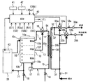
以下、本発明の第1実施形態による貯湯式給湯装置を図1ないし図3に基づいて説明する。図1は本発明を適用させた貯湯式給湯装置の全体構成を示す模式図であり、図2は給湯制御手段である給湯制御部40の制御処理を示すフローチャートである。
(First embodiment)
Hereinafter, a hot water storage type hot water supply apparatus according to a first embodiment of the present invention will be described with reference to FIGS. 1 to 3. FIG. 1 is a schematic diagram showing an overall configuration of a hot water storage type hot water supply apparatus to which the present invention is applied, and FIG. 2 is a flowchart showing a control process of a hot water
本実施形態の貯湯式給湯装置は、一般家庭用として給湯および浴槽へのお湯張りなどの給湯に使用されるものであり、図1に示すように、蓄熱用流体を内部に貯える貯湯タンク10、蓄熱用流体を加熱する加熱手段であるヒートポンプユニット20、蓄熱用流体が流通する第1の流通部30aと給湯用水が流通する第2の流通部30bとを隣接して設け、かつ蓄熱用流体と給湯用水とが対向流となるように構成され、両者間で熱交換を行う給湯用熱交換器30、蓄熱用流体を第1の流通部30aに流通させて貯湯タンク10内の下方部に戻すための1次側循環通路11、本給湯システムの作動を制御する制御装置(給湯制御部40、熱源制御部43)などから構成されている。
The hot water storage type hot water supply apparatus of the present embodiment is used for hot water supply for general household use, such as hot water supply and hot water filling to a bathtub, and as shown in FIG. 1, a hot
本実施形態の貯湯タンク10は、空気孔10aを通じて大気に開放され、貯湯タンク10内部が大気圧に保たれている。この貯湯タンク10は、例えば、樹脂材料で形成され直方体形状に設けられている。また、貯湯タンク10内の蓄熱用流体に貯えられた熱が貯湯タンク10の壁面より大気中へ放出されることを低減するために、貯湯タンク10の外周をグラスウールやウレタン等の断熱材で覆っても良い。
The hot
また、使用される蓄熱用流体は主成分が水であり、防腐剤、凍結防止剤、LLC等が必要に応じて添加されている。なお、これらの他に高比熱を有する蓄熱材料をマイクロカプセルなどの手法にて封入し、それを水に分散混合させるか、またはスリラー化させて流動可能な蓄熱材を用いても良い。 Further, the heat storage fluid used is mainly water, and preservatives, antifreeze agents, LLC, and the like are added as necessary. In addition to these, a heat storage material having a high specific heat may be encapsulated by a technique such as a microcapsule and dispersed in water, or may be made into a thriller and flowable.
また、貯湯タンク10の外壁面には、蓄熱用流体の貯湯量、もしくは貯湯温度を検出するための水温センサである複数(本例では7つ)の貯湯サーミスタ55が縦方向(貯湯タンク10の高さ方向)にほぼ等間隔に配置され、貯湯タンク10内に満たされた蓄熱用流体の各水位レベルでの温度情報を後述する給湯制御手段である給湯制御部40に出力するようになっている。
Further, on the outer wall surface of the hot
従って、給湯制御部40は複数の貯湯サーミスタ55からの温度情報に基づいて、貯湯タンク10内上方の沸き上げられた湯温と貯湯タンク10内下方の沸き上げられる前の低温の蓄熱用流体との境界位置を検出できるとともに、各水位レベルでの蓄熱用流体の湯温を検出できる。なお、複数の貯湯サーミスタ55のうち、最上部に設けられた貯湯サーミスタ55は高温の蓄熱用流体を出湯する出湯温度を検出する機能を有している。
Therefore, based on the temperature information from the plurality of hot
蓄熱用流体を加熱するヒートポンプユニット20は、例えば、炭酸ガスを冷媒として使用することにより、高圧側の冷媒圧力が冷媒の臨界圧力以上となる超臨界ヒートポンプサイクルを使用している。このヒートポンプサイクルは、周知のように図示しない圧縮機、加熱用熱交換器、膨張弁、蒸発器、およびアキュムレータ等の冷凍サイクル機能部品より構成されている。
The
因みに、圧縮機(図示しない)は、内蔵する電動モータ(図示しない)によって駆動され、アキュムレータより吸引した気相冷媒を臨界圧力以上まで圧縮して吐出する。 Incidentally, the compressor (not shown) is driven by a built-in electric motor (not shown), compresses the gaseous refrigerant sucked from the accumulator to a critical pressure or more, and discharges it.
加熱用熱交換器(図示しない)は、冷媒と蓄熱用流体とを熱交換するもので、例えば、冷媒が流れる冷媒通路(図示しない)と蓄熱用流体が流れる加熱用流体通路(図示しない)とが二重管構造に設けられ、かつ冷媒の流れ方向と蓄熱用流体の流れ方向とが対向するように構成された対向流式の加熱用熱交換器(図示しない)である。 A heating heat exchanger (not shown) exchanges heat between a refrigerant and a heat storage fluid. For example, a refrigerant passage (not shown) through which the refrigerant flows and a heating fluid passage (not shown) through which the heat storage fluid flows are provided. Is a counterflow heating heat exchanger (not shown) that is provided in a double-pipe structure and is configured such that the flow direction of the refrigerant and the flow direction of the heat storage fluid are opposed to each other.
膨張弁(図示しない)は、加熱用熱交換器から流出する冷媒を減圧して蒸発器(図示しない)に供給する。蒸発器(図示しない)は、膨張弁(図示しない)で減圧された冷媒を大気との熱交換によって蒸発させる。アキュムレータ(図示しない)は、蒸発器より流出する冷媒を気液分離して、気相冷媒のみ圧縮機に吸引させるとともに、サイクル中の余剰冷媒を蓄えている。 The expansion valve (not shown) depressurizes the refrigerant flowing out from the heating heat exchanger and supplies it to the evaporator (not shown). An evaporator (not shown) evaporates the refrigerant decompressed by an expansion valve (not shown) by heat exchange with the atmosphere. An accumulator (not shown) gas-liquid separates the refrigerant flowing out of the evaporator, sucks only the gas-phase refrigerant into the compressor, and stores excess refrigerant in the cycle.
また、加熱用熱交換器の加熱用流体通路(図示しない)は、流体加熱用通路21を介して貯湯タンク10に接続され、図示しない電動ポンプが作動することで、貯湯タンク10内の蓄熱用流体が循環する。
Further, a heating fluid passage (not shown) of the heating heat exchanger is connected to the hot
ここで、流体加熱用通路21は貯湯タンク10内の最下部の蓄熱用流体を貯湯タンク10内の最上部に送るための循環通路であり、具体的には、流体加熱用通路21の上流端が貯湯タンク10の底部10bに接続され、流体加熱用通路21の下流端が貯湯タンク10の上部10cに接続されている。
Here, the
これにより、加熱用熱交換器(図示せず)で冷媒との熱交換により加熱された蓄熱用流体が貯湯タンク10の上部10cへ送り込まれるため、貯湯タンク10内の上部側から下部側へ向かって順次蓄熱用流体に蓄熱されていく。なお、ヒートポンプユニット20は後述する熱源制御部43からの制御信号により作動するとともに、その作動状態を給湯制御部40に出力するようになっている。
As a result, the heat storage fluid heated by heat exchange with the refrigerant in the heating heat exchanger (not shown) is sent to the
また、ヒートポンプユニット20内のアクチュエータ類は、その動力源として交流電力を用い、主に料金設定の最も安い深夜時間帯における深夜電力を用いて貯湯タンク10内の蓄熱用流体を加熱する沸き上げ運転を行っている。
In addition, the actuators in the
なお、昼間時間帯においても蓄熱用流体の貯湯温度が低下してくると沸き上げ運転を行うよう制御される。因みに、超臨界ヒートポンプサイクルによれば、一般的なヒートポンプサイクルよりも高温(例えば、85〜90℃)の蓄熱用流体を内部に貯えることができる。 Note that, even in the daytime period, when the hot water storage temperature of the heat storage fluid decreases, the boiling operation is controlled. Incidentally, according to the supercritical heat pump cycle, a heat storage fluid having a temperature higher than that of a general heat pump cycle (for example, 85 to 90 ° C.) can be stored therein.
次に、1次側循環通路11は、貯湯タンク10内の蓄熱用流体を後述する給湯用熱交換器30の第1の流通部30a側に流通させ、給湯用熱交換器30で熱交換された蓄熱用流体を貯湯タンク10内の下方部10eに戻すための循環通路であり、高温取り出し管12、中温取り出し管13、往き管14、戻し管15、1次側入口温度調節手段である高中温混合弁16、およびポンプ手段である循環ポンプ17とから構成されている。
Next, the primary-
高温取り出し管12は、貯湯タンク10内に貯えられる蓄熱用流体のうち、高温の蓄熱用流体を取り出すための配管であり、貯湯タンク10内の上方部10dに上流端が接続されている。中温取り出し管13は、貯湯タンク10内に貯えられる蓄熱用流体のうち、高温の蓄熱用流体よりも湯温の低い中温の蓄熱用流体を取り出すための配管であり、貯湯タンク10内の上方部10dと下方部10eとの間の中間部10fに上流端が接続されている。
The high-temperature take-out
往き管14はその上流端が後述する高中温混合弁16の出口側に接続され、下流端が第1の流通部30aの上流端に接続されている。戻し管15はその上流端が第1の流通部30aの下流端に接続され、戻し管15の下流端が貯湯タンク10内の下方部10eに接続されている。
The upstream pipe 14 has an upstream end connected to an outlet side of a high / medium
なお、往き管14には、第1の流通部30aに流入する蓄熱用流体の入口温度を検出する1次側入口温度検出手段である熱交換前サーミスタ54が設けられ、往き管14内の温度情報を後述する給湯制御部40に出力するようにしている。
The forward pipe 14 is provided with a
高中温混合弁16は、高温取り出し管12と中温取り出し管13との下流側合流部位に設けられ、第1の流通部30aに流入する蓄熱用流体の入口温度を調節する温度調節弁であり、それぞれの開口面積比を調節することで、高温取り出し管12から取り出した高温の蓄熱用流体と中温取り出し管13から取り出した中温の蓄熱用流体との混合比を調節するようにしている。
The high / medium
そして、この高中温混合弁16は、後述する給湯制御部40に電気的に接続されており、上記、貯湯サーミスタ55および熱交換前サーミスタ54により検出される蓄熱用流体の温度情報および給湯制御部40で求められた1次側目標温度に基づいて制御される。
The high / medium
ここでは、貯湯タンク10の最上部に設けられた貯湯サーミスタ55が高温の蓄熱用流体を出湯する出湯温度を検出し、中温取り出し配管13の中間部10f近傍に設けられた貯湯サーミスタ55が中温の蓄熱用流体を出湯する出湯温度を検出している。
Here, the hot
そして、熱交換前サーミスタ54により検出された蓄熱用流体の入口温度が1次側目標温度となるように高中温混合弁16で温度制御している。ここで、この1次側目標温度は、給湯用熱交換器30で熱交換される給湯用水の2次側目標温度に基づいて求められるものであって、この2次側目標温度よりも高めの目標温度となるようにしている。
And the temperature control is carried out by the high / medium
具体的には、2次側目標温度を、例えば、設定温度+5℃程度とすれば、1次側目標温度は設定温度+5℃〜10℃程度以下となるように求められる。そして、中間部10f近傍に設けられた貯湯サーミスタ55が1次側目標温度より高いときには、高中温混合弁16により、高温の蓄熱用流体よりも中温の蓄熱用流体を積極的に多く混合させるようにして温度調節するようにしている。
Specifically, if the secondary target temperature is, for example, about the set temperature + 5 ° C., the primary target temperature is determined to be about the set temperature + 5 ° C. to 10 ° C. or less. When the hot
また、中間部10f近傍に設けられた貯湯サーミスタ55が1次側目標温度より低いときには、高中温混合弁16により、中温の蓄熱用流体よりも高温の蓄熱用流体を積極的に多く混合させるようにして温度調節するようにしている。
In addition, when the hot
言い換えれば、給湯用熱交換器30で熱交換される給湯用水の2次側目標温度に基づいて、1次側目標温度が2次側目標温度よりも高めになるように高中温混合弁16により温度調節されるとともに、その1次側目標温度および中間部10f近傍の貯湯サーミスタ55に基づいて中温の蓄熱用流体を出湯するようにしている。ここで、2次側目標温度を請求項で称する目標温度である。
In other words, based on the secondary target temperature of the hot water to be exchanged by the hot
そして、循環ポンプ17は戻し管15の中途に配置されており、貯湯タンク10内の蓄熱用流体を第1の流通部30aに流通させるポンプである。そして、後述する2次側出口温度検出手段である熱交換後サーミスタ52により検出された給湯用熱交換器30で熱交換された給湯用水の出口温度に基づいて回転数が制御されるように後述する給湯制御部40に電気的に接続されている。
And the
言い換えれば、給湯用熱交換器30で熱交換された給湯用水の熱交換後の温度である出口温度に基づいて、第1の流通部30aに流入する蓄熱用流体の流量を循環ポンプ17の回転数によって調節している。
In other words, the flow rate of the heat storage fluid flowing into the
なお、本実施形態では、第1の流通部30aに流入する蓄熱用流体の流量を循環ポンプ17の回転数で調節したが、これに限らず、戻り管15に給湯用熱交換器30で熱交換された熱交換後の蓄熱用流体の出口温度を検出する1次側熱交換後サーミスタ(図示せず)を設けて、熱交換後の蓄熱用流体の出口温度に基づいて1次側循環通路11を循環する流量を循環ポンプ17で制御しても良い。
In the present embodiment, the flow rate of the heat storage fluid flowing into the
これによれば、貯湯タンク10内の下方部10eに戻される蓄熱用流体の出口温度が、所定温度以上とならないように循環ポンプ17の回転数に規制値を設けることができる。従って、所定温度以下の蓄熱用流体を貯湯タンク10内の下方部10eに戻すことができる。
According to this, it is possible to provide a regulation value for the rotational speed of the
なお、1次側循環通路11および流体加熱用通路21の下方部には、それぞれ排水栓18が設けられており、必要に応じて貯湯タンク10内および1次側循環通路11内の蓄熱用流体を手動により排水することができる。
In addition, drain plugs 18 are respectively provided below the primary
次に、給湯用熱交換器30は、1次側循環通路11に接続されて貯湯タンク10内の蓄熱用流体が流れる第1の流通部30aと、給水用配管31および給湯用配管32に接続された第2の流通部30bとを有して、貯湯タンク10の外部に上下方向に配置されている。そして、第1の流通部30aの下流端が貯湯タンク10の下方部10eと連通するように戻し管15に接続され、第1の流通部30aの上流端が往き管14に接続されている。
Next, the hot water
一方、第2の流通部30bは、その上流端が給水用配管31に接続され、下流端が給湯用配管32に接続されている。従って、給湯用熱交換器30は、第1の流通部30aを上から下へ向かって流れる蓄熱用流体の流れ方向と、第2の流通部30bを下から上へ向かって流れる給湯用水の流れ方向とが対向する対向流式の熱交換器である。
On the other hand, as for the
また、給水用配管31の上流には水道配管に接続されて水道水が第2の流通部30bに導水されるようにしている。そして、給水用配管31には給水温度検出手段である給水サーミスタ51が設けられており、給水用配管31を流通する水道水の温度情報を後述する給湯制御部40に出力するようにしている。
Further, upstream of the
さらに、給湯用配管32には、第2の流通部30bにて熱交換された給湯用水の出口温度を検出する2次側出口温度検出手段である熱交換後サーミスタ52が設けられ、給湯用配管32内の温度情報を後述する給湯制御部40に出力するようにしている。そして、給湯用配管32の下流側は台所に通ずる給湯用配管33aと浴室に通ずる給湯用配管33bとに分岐している。
Further, the hot
そして、それぞれの給湯用配管33a、33bの末端には図示しない給湯水栓に接続され、給湯水栓を開弁することで台所への給湯、浴槽へのお湯張りなどが行える。また、それぞれの給湯用配管33a、33bの中途には、給湯温度調節手段である給湯用混合弁34a、34b、給湯サーミスタ53a、53bおよび2次側流量検出手段である流量カウンタ35a、35bが設けられている。
The ends of the hot
給湯用混合弁34a、34bは、給湯用配管33a、33bに出湯させる給湯用水の給湯温度調節する温度調節弁であり、それぞれの開口面積比を調節することで、第2の流通部30bで熱交換された給湯用水と給水用配管31からの水道水とを混合比を調節して所望する給湯温度である設定温度なるように温度調節する。
The hot water
因みに、本実施形態では、第2の流通部30bで熱交換された給湯用水の出口温度は、2次側目標温度である、例えば、設定温度+5℃程度の給湯用水が流入される。そして、給湯用混合弁34a、34bは、後述する給湯制御部40に電気的に接続されており、設定温度、上記給水サーミスタ51、熱交換後サーミスタ52、および給湯サーミスタ53により検出される給湯用水の温度情報に基づいて制御される。
Incidentally, in this embodiment, the outlet temperature of the hot water for which heat is exchanged in the
給湯サーミスタ53a、53bは給湯用配管33a、33b内の温度情報を、流量カウンタ35a、35bは給湯用配管33a、33b内の流量情報を後述する給湯制御部40に出力する。なお、給湯用混合弁34a、34bは、給湯サーミスタ53a、53bにより検出される給湯用水の給湯温度に基づいてフィードバック制御を行うようにしている。
The hot
次に、給湯制御部40は、マイクロコンピュータを主体として構成され、内蔵のROM(図示せず)には、予め設定された制御プログラムが設けられており、各サーミスタ51〜55からの温度情報、流量カウンタ35a、35bからの流量情報および操作盤である台所リモコン41、風呂用リモコン42に設けられた操作スイッチ、設定温度スイッチなどからの操作信号等に基づいて、循環ポンプ17、高中温混合弁16、給湯用混合弁34a、34bなどの1次側循環通路11内および給湯用配管33a、33b内のアクチュエータ類を制御するように構成されている。
Next, the hot water
また、ヒートポンプユニット20には熱源制御部43が設けられ、給湯制御部40に電気的に接続されている。そして、熱源制御部43は、給湯制御部40と同じように、マイクロコンピュータを主体として構成され、内蔵のROM(図示せず)には、予め設定された制御プログラムが設けられており、各種サーミスタからの温度情報などに基づいてヒートポンプユニット20内のアクチュエータ類を制御する。
The
また、熱源制御部43では、加熱用熱交換器(図示しない)で加熱された蓄熱用流体の湯温を一定温度に保つために、最上部に設けられた貯湯サーミスタ55から検出された貯湯温度に基づいて、電動ポンプ(図示しない)の回転数を制御させている。
Further, in the heat
なお、本実施形態では、1次側循環通路11において、貯湯タンク10内の上方部10dと下方部10eとの中間部10fに中温取り出し管13を一つ設けたが、これに限らず、複数の中温取り出し管13を設けて、そのうちのいずれか一つを選択するための図示しない切換弁を設けても良い。
In the present embodiment, one intermediate
これによれば、貯湯タンク10内に貯えられる蓄熱用流体のうち、高温の蓄熱用流体よりも積極的に中温の蓄熱用流体を取り出すことができる。これにより、貯湯タンク10内の下方部10eに戻される蓄熱用流体の温度を低下させることができる。
According to this, among the heat storage fluid stored in the hot
次に、以上の構成による貯湯式給湯装置の作動について説明する。まず、図示しない電源スイッチがオンされると、料金設定の安い深夜時間帯に達すると、熱源制御部43によりヒートポンプユニット20内のヒートポンプサイクル部品(図示しない)と電動ポンプ(図示しない)などのアクチュエータ類を制御させて貯湯タンク10内の蓄熱用流体を加熱して高温(例えば、85℃)の蓄熱用流体が貯湯タンク10内に貯えられる。
Next, the operation of the hot water storage type hot water supply apparatus having the above configuration will be described. First, when a power switch (not shown) is turned on, a heat
そして、貯えられた高温の蓄熱用流体を熱源として、給湯用熱交換器30により熱交換された給湯用水と水道水とを混合させて台所、洗面所、浴槽などの給湯対象箇所に給湯するものである。
Then, using the stored high-temperature heat storage fluid as a heat source, the hot water supplied by the hot water
以下、図2に示すフローチャートに基づいて説明する。図2に示すように、使用者が給湯用配管33a、33bの末端にある給湯水栓(図示しない)を開弁することで、流量カウンタ35a、35bにより流量情報が給湯制御部40に出力される。これにより、ステップ410にて、給湯指令を検知したか否かの判定を行い、所定値以上の流量が流通しておれば、給湯指令を検知したことで給湯制御の制御処理がスタートする。
Hereinafter, description will be made based on the flowchart shown in FIG. As shown in FIG. 2, when the user opens a hot water tap (not shown) at the end of the hot
そして、ステップ420にて、給湯制御部40に入力される設定温度、各種サーミスタからの温度情報、および流量カウンタ35a、35bからの流量情報が読み込まれて記憶される。そして、ステップ430にて、入力した設定温度、流量情報が記憶された温度、流量情報に比べて変化しているか否かを判定する。
In
なお、ここでは、開始直後の最初のデータであるので設定温度、流量情報が変化したと判定されてステップ440に移行する。そして、ステップ440にて、循環ポンプ17の指示回転数を算出する。具体的には、記憶された設定温度から2次側目標温度を求める。そして、その2次側目標温度および流量カウンタ35a、35bからの流量情報に基づいて必要給湯能力を求める。そして、設定温度もしくは2次側目標温度に基づいて1次側目標温度を求める。
Here, since it is the first data immediately after the start, it is determined that the set temperature and flow rate information have changed, and the process proceeds to step 440. In
そして、必要給湯能力、1次側目標温度に基づいて予め設定された1次側供給能力と指示回転数との関係の特性から循環ポンプ17の指示回転数を算出する。そして、ステップ450にて、循環ポンプ17を指示回転数で運転させる。
And the instruction | indication rotation speed of the
この循環ポンプ17の作動により、貯湯タンク10内の蓄熱用流体が第1の流通部30aに流入されるが、ステップ460にて、第1の流通部30aに流入する蓄熱用流体が1次側目標温度となるように高中温混合弁16で温度調節される。
By the operation of the
これにより、第2の流通部30bに流通する給湯用水が蓄熱用流体の熱エネルギーを受けて加熱される。そして、ステップ470にて、熱交換後サーミスタ52により検出される給湯用水の出口温度が2次側目標温度(例えば、設定温度+5℃程度)となるように、循環ポンプ17の回転数をフィードバック制御する。
Thereby, the hot water supply water which distribute | circulates to the
つまり、熱交換後サーミスタ52により検出される出口温度が2次側目標温度より低いときは、循環ポンプ17の回転数を大きくして1次側循環通路11を循環する流量を増加させる。これにより、第1の流通部30aを流れる蓄熱用流体と第2の流通部30bに流通する給湯用水との熱交換量が増加するため、給湯用水の出口温度が上昇する。
That is, when the outlet temperature detected by the
また、逆に、熱交換後サーミスタ52により検出される出口温度が2次側目標温度より高いときは、循環ポンプ17の回転数を小さくして1次側循環通路11を循環する流量を減少させる。これにより、第1の流通部30aを流れる蓄熱用流体と第2の流通部30bに流通する給湯用水との熱交換量が減少するため、給湯用水の出口温度が下降する。
Conversely, when the outlet temperature detected by the
なお、給湯水栓が開弁中に流量もしくは設定温度が変更されると、上述したステップ430にて、入力した設定温度、流量情報が記憶された温度、流量情報に比べて変化しているか否かを判定して、変化があればステップ440にて循環ポンプ17の指示回転数を算出するようにしている。これにより、変化に応じた対応がリアルタイムに反映することができる。
If the flow rate or set temperature is changed while the hot water tap is open, whether or not the input set temperature and flow rate information are changed compared to the stored temperature and flow rate information in
一方、高中温混合弁16では、熱交換前サーミスタ54により検出される蓄熱用流体の入口温度が1次側目標温度(例えば、設定温度+5℃〜10℃程度以下)となるようにフィードバック制御されている。つまり、熱交換前サーミスタ54により検出される蓄熱用流体の入口温度が1次側目標温度よりも低いときは高温の蓄熱用流体を増加させて中温の蓄熱用流体と混合するように制御される。
On the other hand, in the high / medium
また、逆に蓄熱用流体の入口温度が1次側目標温度よりも高いときは中温の蓄熱用流体を増加させて高温の蓄熱用流体と混合するように制御される。これにより、貯湯タンク10内の下方部10eに低温(例えば、給水温度+5℃程度)の蓄熱用流体が戻されることになる。
In contrast, when the inlet temperature of the heat storage fluid is higher than the primary target temperature, the medium temperature heat storage fluid is increased and mixed with the high temperature heat storage fluid. As a result, the heat storage fluid at a low temperature (for example, about the water supply temperature + 5 ° C.) is returned to the
なお、例えば、貯湯タンク10内の蓄熱用流体がヒートポンプユニット20で加熱された後など貯湯タンク10内に高温の蓄熱用流体が多く中温の蓄熱用流体が少ないときは、上記低温の蓄熱用流体よりも高めの温度となって貯湯タンク10内の下方部10eに戻されるが、貯湯タンク10内に戻された蓄熱用流体は、時間の経過とともに、その蓄熱用流体の比重差により上方に高温、下方に低温および上方と下方との間に中間層(中温)が形成される。
For example, when the heat storage fluid in the hot
他方、給湯用混合弁34a、34baでは、第2の流通部30bで熱交換された2次側目標温度(設定温度+5℃程度)の給湯用水と、給水用配管31から給水される水道水とが混合されて設定温度に温度調節される。これにより、所望する給湯温度の給湯用水が給湯水栓から給湯される。
On the other hand, in the hot water
ところで、本実施形態の制御方式では、当初から2次側の給湯熱量に基づいた1次側循環通路11の循環流量を調節するようにしているため若干、給湯水栓を開弁してからの立ち上がり特性が低下する。これを解消するために循環ポンプ17の初期回転数を高めに設定した後に、上述のように1次側循環通路11を循環する流量を調節する方法がある。
By the way, in the control method of this embodiment, since the circulation flow rate of the primary
しかし、この方法では、給湯用水が給湯用配管33a、33bから出湯される流量が高流量のときは熱交換ロスも少なく、かつ貯湯タンク10内の下方部10eに低い温度の状態で戻されることで良好であったが、流量が低流量の給湯や短時間の給湯では、1次側の供給熱量が過大となるため貯湯タンク10内への戻り温度が上昇してしまう欠点があった。
However, in this method, when the flow rate of hot water supplied from the hot
以下、この方法と本発明との戻り温度の比較を行ったので図3に基づいて説明する。図3(a)は給湯水栓を開弁後、5秒程度高めの回転数で循環ポンプ17を作動させて、その後、ステップ470の回転数をフィードバック制御させたときにおける循環ポンプ17の回転数と蓄熱用流体の1次側出口温度との関係を示す特性図である。
Hereinafter, since the return temperature was compared between this method and the present invention, description will be made based on FIG. FIG. 3A shows the rotational speed of the circulating
図3(b)は図2に示すフローチャートに従って循環ポンプ17の回転数と蓄熱用流体の1次側出口温度との関係を示す特性図である。これによれば、図3(a)の方が給湯用熱交換器30の1次側の熱交換ロスが大となるとともに、貯湯タンク10内への戻り温度が上昇している。従って、本発明のように当初から2次側の給湯熱量に基づいた回転数で1次側の流量を調節することにより、貯湯タンク10内の下方部10eに低温の蓄熱用流体を戻すことができる。
FIG. 3B is a characteristic diagram showing the relationship between the rotational speed of the
以上の第1実施形態による貯湯式給湯装置によれば、1次側循環通路11は、貯湯タンク10内に貯えられた蓄熱用流体のうち、高温と中温との蓄熱用流体の両方を混合させて第1の流通部30aに流入するように構成されている。
According to the hot water storage type hot water supply apparatus according to the first embodiment described above, the primary
これにより、中温の蓄熱用流体が使用されて貯湯タンク10内の下方部10eに低温の蓄熱用流体を戻すことができる。従って、ヒートポンプユニット20の沸き上げのときに運転効率の向上が図れる。
Thereby, the medium temperature heat storage fluid is used, and the low temperature heat storage fluid can be returned to the
また、第2の流通部30bに給湯用水が流通されて加熱するときに、少なくとも給湯用熱交換器30で加熱された給湯用水の温度とその流量とに基づいて、第1の流通部30aに流入する蓄熱用流体の温度とその流量とを調節する給湯制御部40を有している。
In addition, when hot water is circulated and heated in the
これによれば、第2の流通部30b側に流通される給湯用水の給湯出力に応じた蓄熱用流体の熱エネルギーを第1の流通部30aに流入することができることで第1の流通部30aから流出した蓄熱用流体の温度を加熱前の給湯用水の温度近傍に接近させることができる。
According to this, the thermal energy of the heat storage fluid according to the hot water supply output of the hot water for water circulated to the
従って、貯湯タンク10内には温度の低い蓄熱用流体が戻されることで、ヒートポンプユニット20の沸き上げのときに運転効率の向上が図れる。しかも、蓄熱用流体と給湯用水との熱交換時における1次側の熱交換ロスを極力小さくすることが可能となり、熱交換効率の優れる給湯システムの実現ができる。
Therefore, the heat storage fluid having a low temperature is returned to the hot
具体的には、設定温度、給湯用熱交換器30により給湯用水を加熱するときの目標温度である2次側目標温度、熱交換前サーミスタ54で検出する蓄熱用流体の入口温度、給水サーミスタ51で検出する給水温度、流量カウンタ35a、35bで検出する2次側の流量、もしくは、熱交換前サーミスタ52で検出する給湯用水の出口温度のいずれかに基づいて、第1の流通部30aに流入する蓄熱用流体の温度とその流量とを調節するようにしている。
Specifically, the set temperature, the secondary target temperature that is the target temperature when heating hot water using the hot water
これによれば、給湯用熱交換器30で加熱された給湯用水の温度とその流量の他に、第1の流通部30aに流入する蓄熱用流体の入口温度、所望する給湯温度、目標温度、もしくは第2の流通部30bに流入する給湯用水の給水温度のいずれかを用いて第1の流通部30aに流入する蓄熱用流体の温度とその流量とを制御することが容易にできる。従って、第2の流通部30b側に変動があっても、それに応じた精度の良い熱交換能力を発揮することができる。
According to this, in addition to the temperature and flow rate of hot water supplied by the hot water
また、循環ポンプ17の回転数を制御して第1の流通部30aに流入する蓄熱用流体の流量を調節することにより、循環ポンプ17で蓄熱用流体の流量を容易に迅速な対応で調節できる。
Further, by controlling the number of rotations of the
また、第1の流通部30aに流入する蓄熱用流体の入口温度を調節するための高中温混合弁16を設けて、第1の流通部30aを流出する出口温度が第2の流通部30bに流入する給湯用水の給水温度の近傍に接近するように給湯制御部40により高中温混合弁16を制御することにより、第1の流通部30aに流入する蓄熱用流体の熱エネルギーを第2の流通部30b側に応じて容易に調節することが可能である。
Further, a high / medium
また、第2の流通部30bの下流側に給湯用混合弁34a、34bを設け、その給湯用混合弁34a、34bを給湯用熱交換器30により2次側目標温度に加熱された給湯用水に給水用配管31からの水道水とを混合して所望する給湯温度に調節する。
Also, hot
これによれば、第2の流通部30b側の給湯用水の出口温度を第1の流通部30aに流入する蓄熱用流体の温度もしくは流量によって第2の流通部30b側の給湯用水の出口温度を調節すると温度変化の応答性が遅いため、温度制御の精度が低下する場合がある。そこで、本発明では給湯用混合弁34a、34bを用いると、給湯用水の温度を所望する給湯温度に精度よく調節できる。
According to this, the outlet temperature of the hot water supply water on the
また、ヒートポンプユニット20は、冷媒の圧力が臨界圧力以上となる超臨界ヒートポンプサイクルであり、臨界圧力以上に昇圧された冷媒により蓄熱用流体を加熱することにより、 超臨界ヒートポンプサイクルにおいては、蓄熱用流体を目標温度(例えば65〜90度)まで加熱する場合、加熱前の蓄熱用流体の温度が低いほど、高圧圧力が低くなることでサイクル効率(COP=加熱能力/消費電力)が向上する。
Further, the
従って、加熱前の給湯用水の温度近傍まで低減された蓄熱用流体を超臨界ヒートポンプサイクルにて加熱することにより、運転効率が向上し省動力運転を行うことができる。 Therefore, by heating the heat storage fluid reduced to near the temperature of the hot water supply water before heating in the supercritical heat pump cycle, the operation efficiency can be improved and power saving operation can be performed.
(第2実施形態)
以上の第1実施形態では循環ポンプ17により第1の流通部30aに流入する蓄熱用流体の流量を調節するようにしたが、これに限らず、図4に示すように、戻り管15の中途に流量調節弁19を設け、給湯制御部40で流量調節弁19の開度を制御して蓄熱用流体の流量を調節するようにしても良い。
(Second Embodiment)
In the first embodiment described above, the flow rate of the heat storage fluid flowing into the
これによれば、第2の流通部30b側に流通される給湯用水の流量の変動範囲において、極低流量のときには、循環ポンプ17の回転数で制御できないことがあるが、循環ポンプ17の他に流量調節弁19を用いても良い。
According to this, in the fluctuation range of the flow rate of the hot water supplied to the
(第3実施形態)
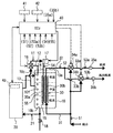
以上の実施形態では、貯湯タンク10の外部に給湯用熱交換器30を配置して1次側循環通路11を構成したが、これに限らず、具体的には、図5に示すように、給湯用熱交換器30を貯湯タンク10内に収容するように構成しても良い。ただし、このときには、1次側循環通路11の戻り管15は、貯湯タンク10内の下方部に配置される。なお、循環ポンプ17は往き管14に設けられている。
(Third embodiment)
In the above embodiment, the hot water
(他の実施形態)
以上の実施形態では、冷媒に二酸化炭素を用いたヒートポンプユニット20を加熱手段として説明したが、これに限らず、フロン、代替フロンなどの冷媒を用いる一般的なヒートポンプサイクルでも良い。
(Other embodiments)
In the above embodiment, the
また、以上の実施形態では、貯湯タンク10は、必ずしも樹脂材料を使用する必要はなく、金属材料で成形しても良い。また、貯湯タンク10の形状は、直方体形状でなくても、例えば円筒形状でも良い。また、貯湯タンク10を大気開放形に形成したが、密閉タイプ構造の貯湯タンクでも良い。ただしこの場合には、減圧弁、圧力逃がし弁などのタンクを保護するための部品が必要となる。
Moreover, in the above embodiment, the hot
10…貯湯タンク
11…1次側循環通路
16…高中温混合弁(1次側入口温度調節手段)
17…循環ポンプ(ポンプ手段)
19…流量調節弁
20…ヒートポンプユニット(加熱手段)
30…給湯用熱交換器
30a…第1の流通部
30b…第2の流通部
34a、34b…給湯用混合弁(給湯温度調節手段)
35a、35b…流量カウンタ(2次側流量検出手段)
40…給湯制御部(給湯制御手段)
51…給水サーミスタ(給水温度検出手段)
52…熱交換後サーミスタ(2次側出口温度検出手段)
54…熱交換前サーミスタ(1次側入口温度検出手段)
DESCRIPTION OF
17 ... Circulation pump (pump means)
19 ...
DESCRIPTION OF
35a, 35b ... flow rate counter (secondary flow rate detection means)
40 ... Hot water supply control unit (hot water supply control means)
51 ... Water supply thermistor (water supply temperature detection means)
52 ... Thermistor after heat exchange (secondary outlet temperature detection means)
54 ... Thermistor before heat exchange (primary inlet temperature detection means)
Claims (7)
前記貯湯タンク(10)内の蓄熱用流体を加熱する加熱手段(20)と、
前記貯湯タンク(10)内に貯えられた蓄熱用流体が流通する第1の流通部(30a)と給湯用水が流通する第2の流通部(30b)とを隣接して設け、かつ蓄熱用流体と給湯用水とが対向流となるように構成され、両者間で熱交換を行う給湯用熱交換器(30)と、
前記貯湯タンク(10)内の蓄熱用流体を前記第1の流通部(30a)に流通させて、前記貯湯タンク(10)内の下方部に戻すための1次側循環通路(11)とを備える貯湯式給湯装置において、
前記1次側循環通路(11)は、前記貯湯タンク(10)内に貯えられた蓄熱用流体のうち、高温の蓄熱用流体と中温の蓄熱用流体との両方を前記第1の流通部(30a)に流入するように構成され、
かつ前記第2の流通部(30b)に給湯用水が流通されて加熱するときに、少なくとも前記給湯用熱交換器(30)で加熱された給湯用水の温度とその流量とに基づいて、前記第1の流通部(30a)に流入する蓄熱用流体の温度とその流量とを調節する給湯制御手段(40)を有することを特徴とする貯湯式給湯装置。 A hot water storage tank (10) for storing heat storage fluid therein;
Heating means (20) for heating the heat storage fluid in the hot water storage tank (10);
A first circulation part (30a) through which the heat storage fluid stored in the hot water storage tank (10) circulates and a second circulation part (30b) through which the hot water supply water circulates are provided adjacent to each other, and the heat storage fluid And the hot water supply water are configured to face each other, and a hot water supply heat exchanger (30) for exchanging heat between the two,
A primary-side circulation passage (11) for circulating the heat storage fluid in the hot water storage tank (10) to the first circulation part (30a) and returning it to the lower part in the hot water storage tank (10). In the hot water storage hot water supply equipment provided,
The primary side circulation path (11), the hot water storage tank (10) of the heat storage fluid which is stored in said both first flow part and the heat storage flow of hot heat storage fluid and medium temperature Configured to flow into (30a),
And when hot water is circulated through the second circulation part (30b) and heated, the temperature of the hot water heated by the hot water heat exchanger (30) and its flow rate are at least determined. A hot water storage type hot water supply apparatus comprising hot water supply control means (40) for adjusting a temperature and a flow rate of a heat storage fluid flowing into one circulation part (30a).
前記第1の流通部(30a)に流入する蓄熱用流体の入口温度を検出する1次側入口温度検出手段(54)と、
前記第2の流通部(30b)に流入する給湯用水の給水温度を検出する給水温度検出手段(51)と、
前記第2の流通部(30b)を通過する給湯用水の流量を検出する2次側流量検出手段(35a、35b)と、
前記第2の流通部(30b)から流出する給湯用水の出口温度を検出する2次側出口温度検出手段(52)とを備え、
所望する給湯温度、前記給湯用熱交換器(30)により給湯用水を加熱するときの目標温度、前記1次側入口温度検出手段(54)によって検出される蓄熱用流体の入口温度、前記給水温度検出手段(51)によって検出される給湯用水の給水温度、前記2次側流量検出手段(35a、35b)によって検出される給湯用水の流量、もしくは前記2次側出口温度検出手段(52)によって検出される給湯用水の出口温度のいずれかに基づいて、前記第1の流通部(30a)に流入する蓄熱用流体の温度とその流量とを調節することを特徴とする請求項1に記載の貯湯式給湯装置。 The hot water supply control means (40)
Primary side inlet temperature detection means (54) for detecting the inlet temperature of the heat storage fluid flowing into the first flow part (30a);
A feed water temperature detection means (51) for detecting a feed water temperature of the hot water supply water flowing into the second circulation part (30b);
Secondary flow rate detection means (35a, 35b) for detecting the flow rate of hot water for water passing through the second circulation part (30b);
A secondary-side outlet temperature detecting means (52) for detecting the outlet temperature of the hot-water supply water flowing out from the second circulation part (30b),
Desired hot water supply temperature, target temperature when heating hot water using the hot water supply heat exchanger (30), inlet temperature of the heat storage fluid detected by the primary side inlet temperature detection means (54), the supply water temperature Detected by the hot water supply water temperature detected by the detection means (51), the hot water flow rate detected by the secondary flow rate detection means (35a, 35b), or the secondary outlet temperature detection means (52) 2. The hot water storage device according to claim 1, wherein the temperature and the flow rate of the heat storage fluid flowing into the first circulation part (30 a) are adjusted based on any one of the outlet temperatures of the hot water supply water. Water heater.
前記給湯制御手段(40)は、前記ポンプ手段(17)の回転数を制御して前記第1の流通部(30a)に流入する蓄熱用流体の流量を調節することを特徴とする請求項1または請求項2記載の貯湯式給湯装置。 The primary side circulation passage (11) is provided with pump means (17) for circulating the heat storage fluid,
The hot water supply control means (40) controls the number of rotations of the pump means (17) to adjust the flow rate of the heat storage fluid flowing into the first circulation part (30a). Or the hot water storage type hot-water supply apparatus of Claim 2.
前記給湯制御手段(40)は、前記ポンプ手段(17)の回転数を一定に制御し、かつ前記流量調節弁(19)を制御して前記第1の流通部(30a)に流入する蓄熱用流体の流量を調節することを特徴とする請求項1または請求項2記載の貯湯式給湯装置。 The primary side circulation passage (11) is provided with a pump means (17) for circulating the heat storage fluid and a flow rate adjusting valve (19) capable of adjusting the flow rate of the heat storage fluid,
The hot water supply control means (40) controls the rotation speed of the pump means (17) to be constant and controls the flow rate control valve (19) to flow into the first circulation part (30a). The hot water storage type hot water supply apparatus according to claim 1 or 2, wherein the flow rate of the fluid is adjusted.
前記給湯制御手段(40)は、前記第1の流通部(30a)を流出する出口温度が前記第2の流通部(30b)に流入する給湯用水の給水温度の近傍に接近するように前記1次側入口温度調節手段(16)を制御することを特徴とする請求項1ないし請求項4のいずれか一項に記載の貯湯式給湯装置。 In the primary side circulation passage (11), the high temperature heat storage fluid extracted from the hot water storage tank (10) is mixed with the medium temperature heat storage fluid extracted from the hot water storage tank (10). A primary inlet temperature adjusting means (16) for adjusting the temperature of the heat storage fluid flowing into the one circulation section (30a) is provided;
The hot water supply control means (40) is configured so that the outlet temperature flowing out of the first circulation part (30a) approaches the vicinity of the water supply temperature of hot water flowing into the second circulation part (30b). The hot water storage type hot water supply apparatus according to any one of claims 1 to 4, wherein the secondary side inlet temperature adjusting means (16) is controlled.
前記目標温度は、所望する給湯温度よりも所定温度高い温度に設定され、
前記給湯温度調節手段(34a、34b)は、前記給湯用熱交換器(30)により前記目標温度に加熱された給湯用水に前記給湯用熱交換器(30)で熱交換される前の給湯用水とを混合して所望する給湯温度に調節することを特徴とする請求項2に記載の貯湯式給湯装置。 On the downstream side of the second circulation part (30b), the hot water supply water before the hot water supply heat exchanger (30) exchanges heat with the hot water supply water heat exchanged by the hot water supply heat exchanger (30). Is provided with hot water supply temperature adjusting means (34a, 34b) for adjusting the temperature of hot water supply water,
The target temperature is set to a temperature that is higher than a desired hot water supply temperature by a predetermined temperature,
The hot water supply temperature adjusting means (34a, 34b) is a hot water supply water before the hot water supply water heated to the target temperature by the hot water supply heat exchanger (30) is heat-exchanged by the hot water supply heat exchanger (30). The hot water storage type hot water supply apparatus according to claim 2 , wherein the hot water supply temperature is adjusted to a desired hot water supply temperature.
Priority Applications (1)
| Application Number | Priority Date | Filing Date | Title |
|---|---|---|---|
| JP2005127001A JP4485406B2 (en) | 2005-04-25 | 2005-04-25 | Hot water storage water heater |
Applications Claiming Priority (1)
| Application Number | Priority Date | Filing Date | Title |
|---|---|---|---|
| JP2005127001A JP4485406B2 (en) | 2005-04-25 | 2005-04-25 | Hot water storage water heater |
Publications (2)
| Publication Number | Publication Date |
|---|---|
| JP2006300489A JP2006300489A (en) | 2006-11-02 |
| JP4485406B2 true JP4485406B2 (en) | 2010-06-23 |
Family
ID=37468979
Family Applications (1)
| Application Number | Title | Priority Date | Filing Date |
|---|---|---|---|
| JP2005127001A Expired - Fee Related JP4485406B2 (en) | 2005-04-25 | 2005-04-25 | Hot water storage water heater |
Country Status (1)
| Country | Link |
|---|---|
| JP (1) | JP4485406B2 (en) |
Families Citing this family (12)
| Publication number | Priority date | Publication date | Assignee | Title |
|---|---|---|---|---|
| JP5067858B2 (en) * | 2007-08-21 | 2012-11-07 | 東芝キヤリア株式会社 | Water heater |
| JP2009250542A (en) * | 2008-04-08 | 2009-10-29 | Hitachi Appliances Inc | Water heater |
| JP4912370B2 (en) * | 2008-08-07 | 2012-04-11 | 三菱電機株式会社 | Pump and heat pump type hot water supply device |
| JP4864060B2 (en) * | 2008-10-03 | 2012-01-25 | 三菱電機株式会社 | Pump and heat pump type hot water supply device |
| JP4901838B2 (en) * | 2008-10-29 | 2012-03-21 | 三菱電機株式会社 | Pump and heat pump type hot water supply device |
| JP2010229904A (en) * | 2009-03-27 | 2010-10-14 | Mitsubishi Electric Corp | Pump, heat pump type hot water supply device, and method for manufacturing pump |
| JP4969602B2 (en) * | 2009-04-07 | 2012-07-04 | 三菱電機株式会社 | Pump, heat pump type hot water supply apparatus and pump manufacturing method |
| KR101142421B1 (en) | 2010-07-15 | 2012-07-13 | 주식회사 동방기공 | Package type pump module and air conditioning and heating system therefor |
| KR101346683B1 (en) * | 2012-04-17 | 2014-01-03 | 이범식 | Treating Liquid Heating and Cooling Apparatus |
| JP6017837B2 (en) * | 2012-05-22 | 2016-11-02 | リンナイ株式会社 | Hot water storage hot water supply system |
| ITVE20130016A1 (en) * | 2013-04-16 | 2014-10-17 | Tecno Pool Spa | FURNISHED COOKING PLANT FOR FOODS. |
| KR101474697B1 (en) | 2014-10-07 | 2014-12-18 | 김상훈 | High efficient heat pump system with counter-flow heat exchanger |
Citations (4)
| Publication number | Priority date | Publication date | Assignee | Title |
|---|---|---|---|---|
| JPH02146459A (en) * | 1988-11-29 | 1990-06-05 | Ebara Corp | Hot water supplying apparatus |
| JP2001153458A (en) * | 1999-11-30 | 2001-06-08 | Denso Corp | Hot water supplier |
| JP2002122352A (en) * | 2000-10-13 | 2002-04-26 | Denso Corp | Water heater |
| JP2003240342A (en) * | 2002-02-18 | 2003-08-27 | Corona Corp | Heat pump type hot water supply system |
-
2005
- 2005-04-25 JP JP2005127001A patent/JP4485406B2/en not_active Expired - Fee Related
Patent Citations (4)
| Publication number | Priority date | Publication date | Assignee | Title |
|---|---|---|---|---|
| JPH02146459A (en) * | 1988-11-29 | 1990-06-05 | Ebara Corp | Hot water supplying apparatus |
| JP2001153458A (en) * | 1999-11-30 | 2001-06-08 | Denso Corp | Hot water supplier |
| JP2002122352A (en) * | 2000-10-13 | 2002-04-26 | Denso Corp | Water heater |
| JP2003240342A (en) * | 2002-02-18 | 2003-08-27 | Corona Corp | Heat pump type hot water supply system |
Also Published As
| Publication number | Publication date |
|---|---|
| JP2006300489A (en) | 2006-11-02 |
Similar Documents
| Publication | Publication Date | Title |
|---|---|---|
| JP4485406B2 (en) | Hot water storage water heater | |
| KR100859245B1 (en) | Heat pump hot water supply floor heating apparatus | |
| EP3163176B1 (en) | Heating and hot water supply system | |
| JP5109300B2 (en) | Hot water storage hot water heater | |
| WO2008113121A1 (en) | A thermal transfer, recovery and management system | |
| JP4839141B2 (en) | Heat pump water heater | |
| JP5245217B2 (en) | Hot water storage hot water heater | |
| JP5482724B2 (en) | Hybrid water heater | |
| JP2005233596A (en) | Heat pump hot-water supply device | |
| JP4158694B2 (en) | Hot water storage type heat pump water heater | |
| JP4207867B2 (en) | Hot water storage water heater | |
| KR101343445B1 (en) | Hybrid hot-water supply apparatus | |
| JP4064356B2 (en) | Hot water storage water heater | |
| JP4101190B2 (en) | Hot water storage water heater | |
| JP2004198055A (en) | Hot water supply type heating device | |
| JP3908768B2 (en) | Heat pump type water heater | |
| JP2005207672A (en) | Hot water storage type water heater | |
| JP2015094569A (en) | Floor heater display device | |
| JP4155140B2 (en) | Hot water storage water heater | |
| JP4155162B2 (en) | Hot water storage water heater | |
| JP4100355B2 (en) | Hot water storage water heater | |
| JP4270101B2 (en) | Hot water storage type multi-function water heater | |
| JP2005201569A (en) | Hot water storage type water heater | |
| JP2005300079A (en) | Storage type hot water supply system | |
| WO2018158827A1 (en) | Heat medium system |
Legal Events
| Date | Code | Title | Description |
|---|---|---|---|
| A621 | Written request for application examination |
Free format text: JAPANESE INTERMEDIATE CODE: A621 Effective date: 20071026 |
|
| A977 | Report on retrieval |
Free format text: JAPANESE INTERMEDIATE CODE: A971007 Effective date: 20091209 |
|
| A131 | Notification of reasons for refusal |
Free format text: JAPANESE INTERMEDIATE CODE: A131 Effective date: 20100112 |
|
| A521 | Written amendment |
Free format text: JAPANESE INTERMEDIATE CODE: A523 Effective date: 20100223 |
|
| TRDD | Decision of grant or rejection written | ||
| A01 | Written decision to grant a patent or to grant a registration (utility model) |
Free format text: JAPANESE INTERMEDIATE CODE: A01 Effective date: 20100323 |
|
| A01 | Written decision to grant a patent or to grant a registration (utility model) |
Free format text: JAPANESE INTERMEDIATE CODE: A01 |
|
| A61 | First payment of annual fees (during grant procedure) |
Free format text: JAPANESE INTERMEDIATE CODE: A61 Effective date: 20100324 |
|
| R150 | Certificate of patent or registration of utility model |
Free format text: JAPANESE INTERMEDIATE CODE: R150 |
|
| FPAY | Renewal fee payment (event date is renewal date of database) |
Free format text: PAYMENT UNTIL: 20130402 Year of fee payment: 3 |
|
| FPAY | Renewal fee payment (event date is renewal date of database) |
Free format text: PAYMENT UNTIL: 20130402 Year of fee payment: 3 |
|
| FPAY | Renewal fee payment (event date is renewal date of database) |
Free format text: PAYMENT UNTIL: 20140402 Year of fee payment: 4 |
|
| R250 | Receipt of annual fees |
Free format text: JAPANESE INTERMEDIATE CODE: R250 |
|
| R250 | Receipt of annual fees |
Free format text: JAPANESE INTERMEDIATE CODE: R250 |
|
| R250 | Receipt of annual fees |
Free format text: JAPANESE INTERMEDIATE CODE: R250 |
|
| S533 | Written request for registration of change of name |
Free format text: JAPANESE INTERMEDIATE CODE: R313533 |
|
| R350 | Written notification of registration of transfer |
Free format text: JAPANESE INTERMEDIATE CODE: R350 |
|
| R250 | Receipt of annual fees |
Free format text: JAPANESE INTERMEDIATE CODE: R250 |
|
| LAPS | Cancellation because of no payment of annual fees |