EP2050477B1 - Unité d'ampoule dotée d'un adaptateur - Google Patents
Unité d'ampoule dotée d'un adaptateur Download PDFInfo
- Publication number
- EP2050477B1 EP2050477B1 EP07118924.5A EP07118924A EP2050477B1 EP 2050477 B1 EP2050477 B1 EP 2050477B1 EP 07118924 A EP07118924 A EP 07118924A EP 2050477 B1 EP2050477 B1 EP 2050477B1
- Authority
- EP
- European Patent Office
- Prior art keywords
- ampoule
- plunger
- thread
- adapter
- unit
- Prior art date
- Legal status (The legal status is an assumption and is not a legal conclusion. Google has not performed a legal analysis and makes no representation as to the accuracy of the status listed.)
- Active
Links
- 239000003708 ampul Substances 0.000 title claims description 164
- 239000012530 fluid Substances 0.000 claims description 29
- 230000033001 locomotion Effects 0.000 claims description 16
- 238000002347 injection Methods 0.000 claims description 7
- 239000007924 injection Substances 0.000 claims description 7
- 238000006073 displacement reaction Methods 0.000 claims description 6
- 239000003814 drug Substances 0.000 claims description 4
- NOESYZHRGYRDHS-UHFFFAOYSA-N insulin Chemical compound N1C(=O)C(NC(=O)C(CCC(N)=O)NC(=O)C(CCC(O)=O)NC(=O)C(C(C)C)NC(=O)C(NC(=O)CN)C(C)CC)CSSCC(C(NC(CO)C(=O)NC(CC(C)C)C(=O)NC(CC=2C=CC(O)=CC=2)C(=O)NC(CCC(N)=O)C(=O)NC(CC(C)C)C(=O)NC(CCC(O)=O)C(=O)NC(CC(N)=O)C(=O)NC(CC=2C=CC(O)=CC=2)C(=O)NC(CSSCC(NC(=O)C(C(C)C)NC(=O)C(CC(C)C)NC(=O)C(CC=2C=CC(O)=CC=2)NC(=O)C(CC(C)C)NC(=O)C(C)NC(=O)C(CCC(O)=O)NC(=O)C(C(C)C)NC(=O)C(CC(C)C)NC(=O)C(CC=2NC=NC=2)NC(=O)C(CO)NC(=O)CNC2=O)C(=O)NCC(=O)NC(CCC(O)=O)C(=O)NC(CCCNC(N)=N)C(=O)NCC(=O)NC(CC=3C=CC=CC=3)C(=O)NC(CC=3C=CC=CC=3)C(=O)NC(CC=3C=CC(O)=CC=3)C(=O)NC(C(C)O)C(=O)N3C(CCC3)C(=O)NC(CCCCN)C(=O)NC(C)C(O)=O)C(=O)NC(CC(N)=O)C(O)=O)=O)NC(=O)C(C(C)CC)NC(=O)C(CO)NC(=O)C(C(C)O)NC(=O)C1CSSCC2NC(=O)C(CC(C)C)NC(=O)C(NC(=O)C(CCC(N)=O)NC(=O)C(CC(N)=O)NC(=O)C(NC(=O)C(N)CC=1C=CC=CC=1)C(C)C)CC1=CN=CN1 NOESYZHRGYRDHS-UHFFFAOYSA-N 0.000 claims description 4
- 229940079593 drug Drugs 0.000 claims description 3
- 102000004877 Insulin Human genes 0.000 claims description 2
- 108090001061 Insulin Proteins 0.000 claims description 2
- 229940088597 hormone Drugs 0.000 claims description 2
- 239000005556 hormone Substances 0.000 claims description 2
- 229940125396 insulin Drugs 0.000 claims description 2
- 238000003466 welding Methods 0.000 claims description 2
- 238000007789 sealing Methods 0.000 description 8
- 238000009826 distribution Methods 0.000 description 7
- 239000000463 material Substances 0.000 description 6
- 230000013011 mating Effects 0.000 description 6
- 230000003068 static effect Effects 0.000 description 5
- 239000000243 solution Substances 0.000 description 4
- 239000000853 adhesive Substances 0.000 description 3
- 230000001070 adhesive effect Effects 0.000 description 3
- 230000008859 change Effects 0.000 description 2
- 230000000694 effects Effects 0.000 description 2
- 238000001746 injection moulding Methods 0.000 description 2
- 230000014759 maintenance of location Effects 0.000 description 2
- 238000004519 manufacturing process Methods 0.000 description 2
- 230000008901 benefit Effects 0.000 description 1
- 230000015572 biosynthetic process Effects 0.000 description 1
- 239000003638 chemical reducing agent Substances 0.000 description 1
- 239000000356 contaminant Substances 0.000 description 1
- 239000002537 cosmetic Substances 0.000 description 1
- 230000003111 delayed effect Effects 0.000 description 1
- 238000011161 development Methods 0.000 description 1
- 230000018109 developmental process Effects 0.000 description 1
- 239000000428 dust Substances 0.000 description 1
- 239000011521 glass Substances 0.000 description 1
- 238000010348 incorporation Methods 0.000 description 1
- 238000001802 infusion Methods 0.000 description 1
- 238000003780 insertion Methods 0.000 description 1
- 230000037431 insertion Effects 0.000 description 1
- 230000003993 interaction Effects 0.000 description 1
- 239000002184 metal Substances 0.000 description 1
- 238000000034 method Methods 0.000 description 1
- 238000002360 preparation method Methods 0.000 description 1
- 230000000717 retained effect Effects 0.000 description 1
- 238000007493 shaping process Methods 0.000 description 1
- 238000004904 shortening Methods 0.000 description 1
- 239000007787 solid Substances 0.000 description 1
- 239000000126 substance Substances 0.000 description 1
- 230000007704 transition Effects 0.000 description 1
Images
Classifications
-
- A—HUMAN NECESSITIES
- A61—MEDICAL OR VETERINARY SCIENCE; HYGIENE
- A61M—DEVICES FOR INTRODUCING MEDIA INTO, OR ONTO, THE BODY; DEVICES FOR TRANSDUCING BODY MEDIA OR FOR TAKING MEDIA FROM THE BODY; DEVICES FOR PRODUCING OR ENDING SLEEP OR STUPOR
- A61M5/00—Devices for bringing media into the body in a subcutaneous, intra-vascular or intramuscular way; Accessories therefor, e.g. filling or cleaning devices, arm-rests
- A61M5/178—Syringes
- A61M5/31—Details
- A61M5/315—Pistons; Piston-rods; Guiding, blocking or restricting the movement of the rod or piston; Appliances on the rod for facilitating dosing ; Dosing mechanisms
- A61M5/31565—Administration mechanisms, i.e. constructional features, modes of administering a dose
- A61M5/31576—Constructional features or modes of drive mechanisms for piston rods
- A61M5/31583—Constructional features or modes of drive mechanisms for piston rods based on rotational translation, i.e. movement of piston rod is caused by relative rotation between the user activated actuator and the piston rod
- A61M5/31586—Constructional features or modes of drive mechanisms for piston rods based on rotational translation, i.e. movement of piston rod is caused by relative rotation between the user activated actuator and the piston rod performed by rotationally moving or pivoted actuator, e.g. an injection lever or handle
-
- A—HUMAN NECESSITIES
- A61—MEDICAL OR VETERINARY SCIENCE; HYGIENE
- A61M—DEVICES FOR INTRODUCING MEDIA INTO, OR ONTO, THE BODY; DEVICES FOR TRANSDUCING BODY MEDIA OR FOR TAKING MEDIA FROM THE BODY; DEVICES FOR PRODUCING OR ENDING SLEEP OR STUPOR
- A61M5/00—Devices for bringing media into the body in a subcutaneous, intra-vascular or intramuscular way; Accessories therefor, e.g. filling or cleaning devices, arm-rests
- A61M5/178—Syringes
- A61M5/31—Details
- A61M5/315—Pistons; Piston-rods; Guiding, blocking or restricting the movement of the rod or piston; Appliances on the rod for facilitating dosing ; Dosing mechanisms
- A61M5/31501—Means for blocking or restricting the movement of the rod or piston
- A61M2005/31508—Means for blocking or restricting the movement of the rod or piston provided on the piston-rod
-
- A—HUMAN NECESSITIES
- A61—MEDICAL OR VETERINARY SCIENCE; HYGIENE
- A61M—DEVICES FOR INTRODUCING MEDIA INTO, OR ONTO, THE BODY; DEVICES FOR TRANSDUCING BODY MEDIA OR FOR TAKING MEDIA FROM THE BODY; DEVICES FOR PRODUCING OR ENDING SLEEP OR STUPOR
- A61M5/00—Devices for bringing media into the body in a subcutaneous, intra-vascular or intramuscular way; Accessories therefor, e.g. filling or cleaning devices, arm-rests
- A61M5/178—Syringes
- A61M5/24—Ampoule syringes, i.e. syringes with needle for use in combination with replaceable ampoules or carpules, e.g. automatic
-
- A—HUMAN NECESSITIES
- A61—MEDICAL OR VETERINARY SCIENCE; HYGIENE
- A61M—DEVICES FOR INTRODUCING MEDIA INTO, OR ONTO, THE BODY; DEVICES FOR TRANSDUCING BODY MEDIA OR FOR TAKING MEDIA FROM THE BODY; DEVICES FOR PRODUCING OR ENDING SLEEP OR STUPOR
- A61M5/00—Devices for bringing media into the body in a subcutaneous, intra-vascular or intramuscular way; Accessories therefor, e.g. filling or cleaning devices, arm-rests
- A61M5/178—Syringes
- A61M5/31—Details
- A61M5/3129—Syringe barrels
- A61M5/3135—Syringe barrels characterised by constructional features of the proximal end
-
- A—HUMAN NECESSITIES
- A61—MEDICAL OR VETERINARY SCIENCE; HYGIENE
- A61M—DEVICES FOR INTRODUCING MEDIA INTO, OR ONTO, THE BODY; DEVICES FOR TRANSDUCING BODY MEDIA OR FOR TAKING MEDIA FROM THE BODY; DEVICES FOR PRODUCING OR ENDING SLEEP OR STUPOR
- A61M5/00—Devices for bringing media into the body in a subcutaneous, intra-vascular or intramuscular way; Accessories therefor, e.g. filling or cleaning devices, arm-rests
- A61M5/178—Syringes
- A61M5/31—Details
- A61M5/3129—Syringe barrels
- A61M5/3137—Specially designed finger grip means, e.g. for easy manipulation of the syringe rod
-
- A—HUMAN NECESSITIES
- A61—MEDICAL OR VETERINARY SCIENCE; HYGIENE
- A61M—DEVICES FOR INTRODUCING MEDIA INTO, OR ONTO, THE BODY; DEVICES FOR TRANSDUCING BODY MEDIA OR FOR TAKING MEDIA FROM THE BODY; DEVICES FOR PRODUCING OR ENDING SLEEP OR STUPOR
- A61M5/00—Devices for bringing media into the body in a subcutaneous, intra-vascular or intramuscular way; Accessories therefor, e.g. filling or cleaning devices, arm-rests
- A61M5/178—Syringes
- A61M5/31—Details
- A61M5/315—Pistons; Piston-rods; Guiding, blocking or restricting the movement of the rod or piston; Appliances on the rod for facilitating dosing ; Dosing mechanisms
- A61M5/31511—Piston or piston-rod constructions, e.g. connection of piston with piston-rod
- A61M5/31513—Piston constructions to improve sealing or sliding
Definitions
- the invention relates to an ampoule unit for incorporation into an administration device, preferably an injection device or less preferably an injection syringe, wherein the ampoule unit comprises at least one ampoule and an adapter, and the ampoule with the adapter, which may have a thread other than about this thread twisted - And secure against displacement is connectable.
- the US 2003/0167039 A1 describes a pump for dispensing a fluid from a reservoir.
- the pump consists of a first part for receiving the reservoir with piston unit, for example an ampoule, and a second part, for receiving the motor and the piston propulsion device. Both parts are arranged side by side, which reduces the overall length of the pump.
- On the back of the piston unit acts a rigid, fixedly connected to a mother plate sitting on a rotary driven threaded rod, which is connected to a motor. If the motor rotates, the nut moves in the direction of advance and pushes the piston unit in a linear movement in the direction of the fluid distribution via the plate.
- the threaded rod can be connected via a gear directly to the piston rod.
- the piston rod is in a threaded connection with the piston and moves it linearly in the advancing direction.
- a drive device for an infusion pump is known.
- FIG. 4 For example, as described in paragraph 0030, an ampoule is shown having an internal thread into which a piston engages an external thread which is thereby screwed into the ampoule rotating about its axis of rotation, thereby emptying the fluid contained in the ampoule.
- the internal thread To the ampoule of EP 1 752 172 A1 To completely empty, the internal thread must be formed over the entire inner length of the ampoule.
- a syringe is known, with a syringe body with an external thread on which a nut can be screwed with a first internal thread.
- the nut has a second internal thread into which a piston rod can be screwed in to dispense the contents of the syringe and screwed in the dispensing direction.
- the WO 2004/016303 A1 describes a syringe consisting of a vial with a pronounced collar at the proximal end and an adapter, the can be postponed or clipped on the federal government.
- the adapter has an internal thread, into which a piston rod can be screwed, whereby the product is released from the ampoule.
- US 5059179 shows a manually operated disposable syringe for medical fluids, which is designed such that it can not be filled a second time after filling once from the empty state and subsequent proper emptying.
- the piston rod is irreversibly separated from the piston.
- the piston rod and piston are connected via a first thread.
- the second externally threaded piston rod is rotated in a first direction of rotation upon withdrawal by a mating thread of a nut fixedly attached to the proximal end of the cylinder.
- the first thread on the piston is opposite to the second thread, so that the piston is dragged along when pulling out.
- the ampoule unit according to the invention according to claim 1 comprises an ampoule, preferably a commercially available ampoule for an administering device with a proximal and a distal end. It should always be referred to as the proximal end of the ampoule that when using the ampoule in the administering device away from the delivery side, which is connected or connectable, for example, with an injection needle or injection nozzle, via which the fluid contained in the ampoule into a human or animal Body is discharged, points. Accordingly, the side of the ampoule opposite the proximal side is referred to as distal, which can be connected for use with the ampoule unit, for example with a needle carrier, needle or nozzle, or is already connected to one of these elements in the delivery state.
- the ampoule can be stored as an empty ampoule, which is filled with the fluid shortly before use, but it can also be supplied already filled to the user, which is the preferred method of delivery, in particular in the case of delivery to a self-contaminant.
- the ampoule unit comprises, in addition to the ampoule, an adapter which is connected to the ampoule in a manner that prevents rotation and displacement and at least partially surrounds the ampoule and / or partially engages the ampoule.
- the adapter may consist of the same material as the ampoule, for example glass or plastic, but it may also consist of another material, for example metal or plastic. It is usually made separately from the ampoule and connected to the ampoule at a later date. This connection can be made by positive engagement, bonding, welding or other connections as long as it is ensured that the ampoule can not move relative to the adapter either longitudinally or circumferentially.
- ampoule bodies can be manufactured or purchased in large quantities, and the adapters for, for example, different delivery cans with threads of different pitch can be produced in smaller quantities.
- the necessary second step of assembling the ampoule and adapter could then only be made immediately before filling the ampoules, or in the case of unfilled ampoules immediately before their delivery.
- the adapter has a thread which is in threaded engagement with the mating thread of a displacer body in the ampule which causes release of the product from the ampule through the distal opening of the ampule.
- the adapter preferably has a thread at least at its proximal end.
- a simple nut which is fastened or attachable to the proximal end of the ampoule can serve as an adapter.
- the ampoule is in this case preferably a commercially available ampoule body.
- the adapter can also partially surround the ampoule, or protrude into the ampoule in the proximal region. In addition, he can also completely surround the ampoule in the sense that the ampoule is receivable in the adapter.
- the adapter can also be applied directly to the ampoule in a form-fitting manner, for example shrunk or sprayed on.
- connection between the adapter and the ampoule can also be detachable, that is, the ampoule can be subsequently inserted into the adapter and removed from the adapter after emptying.
- the ampoule can be subsequently inserted into the adapter and removed from the adapter after emptying.
- the adapter for example, be formed on the outside of the ampoule body latching elements, which provide with locking counter-elements on the adapter for a twist-proof and secure connection between the adapter and ampoule. It is important in any case that the adapter can not move relative to the ampoule, but that the two parts can perform any linear movement and any rotational movement only as a unit.
- the adapter can also be formed directly from the inside of the housing as part of the housing of the administering device or be connected as a separate part fixed to the housing.
- the ampoule unit comprises a piston unit for delivering the fluid product. Pressure is then applied to the fluid product via this piston unit to effect, for example, its release from the ampule and its injection into a tissue.
- the piston unit which consists for example of a piston and a piston rod, a thread on the piston or on the piston rod, which forms a mating thread to the thread of the adapter. Both threads are brought into a threaded engagement, that is, the piston unit is screwed in or on the example proximal end of the adapter or.
- the piston is inserted into the proximal end of the ampoule and is screwed in a further rectified rotation in the ampoule in the advancing direction.
- the piston of the piston unit can be made of a material that is elastic enough that it seals the ampoule in the proximal direction and at the same time has the lowest possible sliding friction resistance with the material of the inside of the ampoule.
- a seal may be attached to the distal piston surface.
- the piston may have a concave shape at its periphery, whereby the contact area between the piston and ampoule inner wall is limited to the advancing in the advancing direction and trailing end of the piston.
- the piston can also consist of a hard cylinder core, on which one, two or more sealing rings are molded. The material of the sealing rings can be chosen so that high density and low frictional resistance can be achieved.
- the ampoule inside and / or the piston outer side or the seals may be coated with a friction reducing agent.
- the thread of the adapter can basically be an internal or external thread.
- the thread is formed on the outer wall of the adapter.
- the side of the adapter is referred to, which points away from the ampoule to the outside.
- an internal thread of the adapter is mentioned, then it is to be understood a thread whose teeth protrude from the adapter in the direction of the axis of rotation of the ampoule, regardless of whether they, as for example when the intrusion of the adapter into the proximal end of the ampoule to the outside of which are molded.
- the piston unit is shaped so that on the one hand the mating thread with the thread of the adapter is in threaded engagement, while at the same time a central part of the piston unit causes the discharge of the fluid product from the ampoule.
- the thread of the adapter is an internal thread, which means that the adapter extends from the proximal side into the ampoule and the piston unit can be screwed into the adapter thread from the proximal side of the ampoule unit. Since the thread in this embodiment is preferably formed only in a proximal end portion of the ampoule, the ampoule can be closed in this case in the proximal direction by a sealing element, preferably a sealing disc, for example, directly applied to a perpendicular projecting from the ampoule wall wag shortcuten adapter end.
- the sealing disc has an axial thickness and can be connected to the piston unit by, for example, positive engagement so that it rotates with the screwing into the ampoule piston and continues to serve as a sealing element.
- the sealing disc can also form the piston of the piston unit in the context of the invention. Reaching into the proximal end means here that the adapter lies defacto on the outside of the adapter and that its proximal end is bent around the proximal end of the ampule, so that the bent end of the adapter extends into the proximal end of the ampule.
- Thread and counter thread usually have a thread pitch of 0 mm / U to 2 mm / rev, preferably between 0.5 mm / rev and 2 mm / rev. Less preferably, the thread pitch can also be in the range ⁇ 1 mm / U, in some cases more than 2 mm / U amount.
- the piston assembly which may be in one piece, is threaded into the ampule assembly in the event of threaded engagement between the piston assembly and adapter to dispense the fluid product. That is, the distribution-causing part of the piston unit, that is, the front end thereof in the case of the female-threaded solution or in the case of the male-threaded solution, the part guided in the ampoule, is screwed around its longitudinal axis into the ampoule unit secured against co-rotation.
- This combined rotary and linear movement of the piston unit causes the dispensing-causing front end of the piston unit to travel a spiral path that is greater than the path of a purely linear motion, as is conventional in the art.
- a longer path makes it possible to overcome the static friction between the inner part of the ampoule and the outer surface of the piston unit and the transition to sliding friction.
- the adapter may be threaded at least at its proximal end.
- the formation of the thread is not limited to the proximal end, in particular in the case of the external thread solution, but rather the adapter outer side can be shaped overall as a thread.
- the adapter has an internal thread which cooperates with an external thread of the piston unit. Again, for example, not the entire length of the reaching into the ampoule adapter part must be designed as a thread.
- the piston unit may be formed by a piston alone or by a combination of piston and piston rod. If the piston unit consists of piston and piston rod, the counter thread which can be brought into engagement with the thread of the adapter can be formed either on the piston or on the piston rod.
- the piston and the piston rod may be integrally formed. They may for example consist of plastic and be produced by means of an injection molding process, for example, the two-component injection molding. However, the piston and piston rod can also be separate parts which are non-releasably connected to one another, for example by means of an adhesive or welded connection. Finally, the piston can also be releasably connected to the piston rod, wherein the connection can be a screw or plug connection.
- piston and piston rod always rotate together around their axis of rotation when the piston unit is screwed into the ampoule unit. That is, the piston must not move relative to the piston rod in the connected state when the entirety of the piston and piston rod is screwed into the ampule unit.
- the foremost end of the piston may form a seal, which is formed on the piston during manufacture or torsion-proof connected to the piston, for example, welded, is.
- the piston unit can also be formed from the piston, a sleeve fixedly connected to the piston, which carries the thread, and a drive element.
- the sleeve has a recess in the longitudinal direction, for example, a square blind hole, in which the drive element, in this case a suitably trained square bar engages positively. If the drive element is now driven, for example via a toothed wheel connected to its proximal end, the sleeve and the piston automatically rotate with and are screwed through the threaded connection between sleeve and adapter in the direction of the distribution.
- the adapter may be a disposable device that is disposed of after the vial has been completely emptied or a reusable unit from which an empty vial may be removed and a new full vial inserted. This allows both parts to be disposed of independently and recycled.
- ampoule units can be used in both stationary and mobile delivery devices.
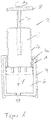
- an ampoule 1 can be seen, which is received in an adapter 4 and connected to a piston unit 2.
- the ampoule 1 has a distal opening 10 for dispensing the ampoule contents from the fluid chamber 6 and a proximal opening for receiving and guiding a displacement unit, in this case the piston unit 2.
- a portion of the adapter 4 extends with a formed on this portion of the adapter 4 thread 4a, in the sense of this description an internal thread into it.
- the thread 4a extends over the entire portion lying in the ampoule 1 up to its most proximal end.
- the thread 4a can also be integrally formed only on a part of the adapter section extending into the ampoule 1, for example displaced further in the distal direction. It is important that the adapter 4 holds the ampoule resistant to rotation and displacement. That is, the adapter 4 forms, for example, a largely rigid sleeve, in which the ampoule 1 can be inserted, with a distal end, which surrounds the distal end of the ampoule 1, and a proximal end, which surrounds the proximal end of the ampoule 1. In the exemplary embodiment shown, the ampoule 1 can be introduced, for example, from the distal side into the adapter 4.
- the adapter 4 at its distal end, for example, no closed cylindrical shape, but elements that bend elastically during insertion of the ampoule 1 outward and fully inserted ampoule 1, that is, when the proximal outer end of the ampoule 1 at the proximal inner End of the adapter 4 is applied, spring back to their original position and keep the ampoule 1 safe to move.
- the proximal inner end of the adapter is defined in the embodiment shown by the proximal end of the cavity, which forms the adapter 4 at its proximal end by the turning around the proximal end of the ampoule.
- FIG. 1 a To pour out the contents of the fluid chamber 6 is in FIG. 1 a cooperating with the adapter 4 piston unit 2 shown.
- This piston unit 2 consists of a central piston 2b, which has an outer diameter which substantially corresponds to the inner diameter of the ampoule 1.
- the central piston At its foremost, distal end, the central piston has a seal 5, which prevents the contents of the ampoule 1 from leaking out of the ampoule 1 during the discharge.
- This seal 5 may be firmly connected to the central piston 2b, but it is preferably already in the provision of the Ampoule 1 as a proximal seal and is carried along by the piston unit 2 in the distribution in the distal direction.
- the piston unit 2 To dispense the piston unit 2 is connected to a drive 7, 8, which sets the piston unit 2 in rotation about its axis of rotation, whereby the piston unit 2 in the threaded connection 2a, 4a screwed into the ampoule 1 and the distribution of the contents of the ampoule 1 through the opening 10 causes.
- a purely linear movement of the central piston 2b in the discharge direction V is not possible. Only by a rotation of the piston unit 2, the central piston 2b can be screwed into the ampoule 1 via the thread 4a and the mating thread 2a.
- the central piston 2b screwing into the ampoule 1 therefore has to cover a larger path than would be the case with a purely linear movement.
- the predetermined amount of discharge is always achieved with great reliability.
- a falsification of the individual discharge amount by slip-stick problems or a long chain of extension of the system is largely excluded.
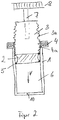
- FIG. 2 shows a second embodiment of the ampoule unit.
- an adapter 4 in the form of a nut with internal thread firmly connected.
- solid means that the nut or adapter 4 can not move linearly or rotationally relative to the ampoule 1. This can be achieved by a suitable adhesive or welded connection, as well as by a corresponding shaping of the ampoule end, in which the adapter 4 is held positively and secured against any relative movement to the ampoule unit 1.
- the piston 2 is concave in the embodiment on its outer side and has at the upper and lower end circumferentially depending on a seal 5. It can be shaped as an independent item and serve as a rear seal in the delivery state of the ampoule 1. In this case, it has at its proximal, that is, the propulsion direction V opposite side, connecting elements, with which it can be connected against rotation with a piston rod 3.
- the piston rod 3 has an external thread 3 a, which is a mating thread to the internal thread of the adapter 4. That is, the threaded rod 3 can rotate with its thread 3 a in the thread 4 a of the adapter 4 and screwed thereby in the advancing direction V in the ampoule 1 inside.
- the piston rod 3 may be connected directly or via a connecting piece, not shown, via a drive element 7 with a gear 8 that is driven by a motor or by hand and thereby screws the piston 2 in the advancing direction V.
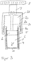
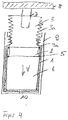
- a third embodiment shows FIG. 3 ,
- the ampoule 1 is held in an adapter 4, which partially surrounds it, so that the adapter 4 can move relative to the ampoule 1 neither linear nor rotary.
- the adapter 4 can be positively connected to the ampoule 1, glued, welded or shrunk. The only important thing is the largely rigid connection of the two parts, which allows no relative movement between ampoule 1 and adapter 4.
- the adapter 4 has in its rear, proximal region an external thread in the sense of the description. With this in threaded engagement is a piston unit, which like the piston unit of FIG. 1 is trained and for which the said there applies accordingly.
- the adapter 4 according to the invention is formed here by a housing 9.
- This housing 9 may be, for example, the housing of the administering device, or the housing of a subunit of the administering device, which is used as a whole in the administering device.
- the integrally formed on the inside of the housing wall thread 9a is above an ampoule inserted into the housing 1.
- the ampoule 1 is held in the housing 9 against rotation and 29iebeclarêt.
- the internal thread 9a of the housing 9 With the internal thread 9a of the housing 9, the external thread 2a of a piston unit 2 in threaded engagement.
Claims (15)
- Unité d'ampoule pour un appareil d'administration, notamment un appareil d'injection ou une seringue d'injection, l'unité d'ampoule étant constituée pour la délivrance répétée reproductible de petites quantités d'un médicament liquide, le médicament liquide comprenant l'insuline ou une préparation hormonale, comprenant
une ampoule (1) avec une extrémité distale avec une ouverture (10) pour délivrer un produit liquide et une extrémité proximale avec une ouverture pour recevoir une unité de corps de déplacement,
un adaptateur (4) qui est relié à l'ampoule (1) de façon solidaire en rotation et en déplacement par collage, soudage ou autres liaisons de telle sorte qu'il est assuré que l'ampoule ne pourra se déplacer relativement vers l'adaptateur ni en direction longitudinale ni en direction périphérique, et
une unité de piston (2,3), laquelle forme l'unité de corps de déplacement,
l'adaptateur (4) étant doté d'un filetage (4a) et un contre-filetage (2a,3a) étant formé sur l'unité de piston (2,3) pour le filetage (4a) de l'adaptateur (4), qui est en prise de filetage avec celle-ci, caractérisée en ce que
l'unité de piston (2,3) est reliée à un système d'entraînement (7,8) qui est constitué pour déplacer en rotation l'unité de piston (2,3) autour d'un axe de rotation, l'unité de piston (2,3) se vissant de ce fait dans l'ampoule en raison de la prise en filetage entre le filetage (4a) de l'adaptateur (4) et le contre-filetage (2a,3a) de l'unité de piston (2,3) et générant la délivrance du produit liquide par l'ouverture (10). - Unité d'ampoule selon l'une quelconque des revendications précédentes, le pas de filetage du filetage (4a) et du contre-filetage (2a,3a) étant ≤ 2mm/tr.
- Unité d'ampoule selon l'une quelconque des revendications précédentes, le pas de filetage du filetage se situant dans une plage de 0,5 mm/tr ≤ 2mm/tr.
- Unité d'ampoule selon l'une quelconque des revendications précédentes, s'agissant d'un filetage intérieur pour le filetage (4a) et d'un filetage extérieur pour le contre-filetage (2a,3a), ou vice versa.
- Unité d'ampoule selon l'une quelconque des revendications 1 à 4, un écrou, relié fermement à l'extrémité proximale de l'ampoule (1), formant l'adaptateur (4).
- Unité d'ampoule selon l'une quelconque des revendications 1 à 4, l'adaptateur (4) entourant au moins en partie l'ampoule (1) et étant relié de façon indissociable à l'ampoule (1).
- Unité d'ampoule selon la revendication 6, l'adaptateur (4) étant projeté ou emmanché sur l'ampoule (1)
- Unité d'ampoule selon l'une quelconque des revendications 1 à 7, un piston (2) formant l'unité de piston.
- Unité d'ampoule selon l'une quelconque des revendications 1 à 7, l'unité de piston (2,3) étant composée d'un piston (2) et d'une tige de piston (3) et le contre-filetage (2a,3a) étant formé sur le piston (2) et/ou sur la tige de piston (3).
- Unité d'ampoule selon la revendication 9, caractérisée en ce que le piston (2) est relié solidaire en rotation à la tige de piston (3) de telle sorte que le piston effectue conjointement chaque mouvement de rotation de la tige de piston avec laquelle le piston se visse intérieurement dans l'ampoule (1) en direction distale.
- Unité d'ampoule selon la revendication 9 ou 10, caractérisée en ce que le côté extérieur du piston (2) est de forme concave et le piston comporte respectivement un joint d'étanchéité (5) à son extrémité distale et à son extrémité proximale.
- Unité d'ampoule selon l'une quelconque des revendications 9 à 11, le piston (2) étant relié de façon dissociable à la tige de piston (3), par exemple par un raccord à vis ou enfichable.
- Unité d'ampoule selon l'une quelconque des revendications 9 à 11, le piston (2) étant relié de façon indissociable à la tige de piston (3).
- Unité d'ampoule selon la revendication 13, le piston (2) et la tige de piston (3) étant formés en une seule pièce, de préférence en matière plastique.
- Unité d'ampoule selon l'une quelconque des revendications précédentes, le piston (2) ou la tige de piston (3) pouvant être reliés à un système d'entraînement qui entraîne de façon rotative le piston (2) et la tige de piston (3).
Priority Applications (4)
| Application Number | Priority Date | Filing Date | Title |
|---|---|---|---|
| EP07118924.5A EP2050477B1 (fr) | 2007-10-19 | 2007-10-19 | Unité d'ampoule dotée d'un adaptateur |
| DK07118924.5T DK2050477T3 (en) | 2007-10-19 | 2007-10-19 | Ampoule unit with adapter |
| PCT/EP2008/008677 WO2009049858A1 (fr) | 2007-10-19 | 2008-10-14 | Unité d'ampoule à filetage |
| US12/762,828 US9108004B2 (en) | 2007-10-19 | 2010-04-19 | Ampoule unit with thread |
Applications Claiming Priority (1)
| Application Number | Priority Date | Filing Date | Title |
|---|---|---|---|
| EP07118924.5A EP2050477B1 (fr) | 2007-10-19 | 2007-10-19 | Unité d'ampoule dotée d'un adaptateur |
Publications (2)
| Publication Number | Publication Date |
|---|---|
| EP2050477A1 EP2050477A1 (fr) | 2009-04-22 |
| EP2050477B1 true EP2050477B1 (fr) | 2018-12-26 |
Family
ID=38885295
Family Applications (1)
| Application Number | Title | Priority Date | Filing Date |
|---|---|---|---|
| EP07118924.5A Active EP2050477B1 (fr) | 2007-10-19 | 2007-10-19 | Unité d'ampoule dotée d'un adaptateur |
Country Status (4)
| Country | Link |
|---|---|
| US (1) | US9108004B2 (fr) |
| EP (1) | EP2050477B1 (fr) |
| DK (1) | DK2050477T3 (fr) |
| WO (1) | WO2009049858A1 (fr) |
Families Citing this family (16)
| Publication number | Priority date | Publication date | Assignee | Title |
|---|---|---|---|---|
| EP2050477B1 (fr) | 2007-10-19 | 2018-12-26 | F.Hoffmann-La Roche Ag | Unité d'ampoule dotée d'un adaptateur |
| WO2011023629A1 (fr) | 2009-08-27 | 2011-03-03 | Sanofi-Aventis Deutschland Gmbh | Dispositif d'injection |
| CA2743198C (fr) * | 2010-06-18 | 2019-06-11 | Lawrence H. Chanoch | Piston de reglage de la dose pour seringue |
| GB201015799D0 (en) | 2010-09-21 | 2010-10-27 | Owen Mumford Ltd | Autoinjectors |
| IT1403866B1 (it) * | 2010-09-30 | 2013-11-08 | Ungaro | Dosatore multiuso per materiale fluido o in pasta |
| TN2015000492A1 (en) * | 2013-06-05 | 2017-04-06 | Injecto As | Piston for use a syringe with specific dimensional ratio of a sealing structure |
| US9457153B2 (en) | 2014-08-29 | 2016-10-04 | Vascular Insights Llc | Syringe accessory |
| DE102014217773A1 (de) * | 2014-09-05 | 2016-03-10 | Vetter Pharma-Fertigung GmbH & Co. KG | Pen |
| US20170056916A1 (en) * | 2015-08-29 | 2017-03-02 | Malic Bedford | Silicon ball in a glass tube advanced by threaded rod dispensing micro amounts of oils or other materials |
| CN106540360B (zh) * | 2016-11-07 | 2020-03-20 | 青岛市肿瘤医院 | 自废型一次性注射器 |
| JP6764319B2 (ja) * | 2016-11-16 | 2020-09-30 | Phcホールディングス株式会社 | 薬剤注入装置 |
| CN110582314B (zh) | 2017-05-11 | 2022-04-05 | 诺和诺德股份有限公司 | 活塞杆制动机构 |
| CN110507879A (zh) * | 2018-05-22 | 2019-11-29 | 佛山市嘉懿行农业科技有限公司 | 一种预充注射装置 |
| CH715144A1 (fr) * | 2018-07-02 | 2020-01-15 | Edelweiss Dr Ag | Dispositif d’extrusion et système de distribution de composite. |
| CN114306816B (zh) * | 2021-12-20 | 2023-11-10 | 中山大学附属第三医院(中山大学肝脏病医院) | 一种细胞制剂贮存注射器 |
| US20230242325A1 (en) * | 2022-01-31 | 2023-08-03 | Paulo Roberto Jannotti Newlands | Ecologically sustainable dispenser |
Citations (1)
| Publication number | Priority date | Publication date | Assignee | Title |
|---|---|---|---|---|
| US5059179A (en) * | 1989-05-15 | 1991-10-22 | David Quatrochi | Non-reusable syringe assembly |
Family Cites Families (13)
| Publication number | Priority date | Publication date | Assignee | Title |
|---|---|---|---|---|
| US2165597A (en) * | 1936-09-14 | 1939-07-11 | Sr Frederick Widoe | Method for forming dentures |
| US2475939A (en) * | 1946-07-12 | 1949-07-12 | Applezweig Norman | Cartridge syringe |
| US3128765A (en) * | 1962-07-17 | 1964-04-14 | American Home Prod | Hypodermic syringe and dose dispenser |
| DE7603096U1 (de) | 1976-02-04 | 1976-08-19 | Espe Pharm Praep | Vorrichtung zur dosierten Abgabe viskoser Massen |
| US4312343A (en) * | 1979-07-30 | 1982-01-26 | Leveen Harry H | Syringe |
| US4583974A (en) * | 1984-04-04 | 1986-04-22 | Kokernak Denis T | Syringe for balloon dilation catheters |
| US5618273A (en) * | 1995-03-27 | 1997-04-08 | Ultradent Product, Inc. | Syringe apparatus with threaded plunger for delivering tooth composites and other solid yet pliable materials |
| US7018365B2 (en) | 1999-05-21 | 2006-03-28 | Micro Therapeutics, Inc. | Threaded syringe with quick stop |
| US6571992B2 (en) | 2001-01-12 | 2003-06-03 | Dentsply Research & Development Corp. | Dispensing syringe |
| WO2003033363A1 (fr) * | 2001-10-16 | 2003-04-24 | Medical Instill Technologies, Inc. | Distributeur presentant une chambre etanche et une valve anti-reflux permettant d'administrer des doses mesurees de substances |
| US6955716B2 (en) | 2002-03-01 | 2005-10-18 | American Dental Association Foundation | Self-hardening calcium phosphate materials with high resistance to fracture, controlled strength histories and tailored macropore formation rates |
| EP1752172A1 (fr) | 2005-08-12 | 2007-02-14 | F.Hoffmann-La Roche Ag | Méchanisme de entraînement pour une pompe à infusion |
| EP2050477B1 (fr) | 2007-10-19 | 2018-12-26 | F.Hoffmann-La Roche Ag | Unité d'ampoule dotée d'un adaptateur |
-
2007
- 2007-10-19 EP EP07118924.5A patent/EP2050477B1/fr active Active
- 2007-10-19 DK DK07118924.5T patent/DK2050477T3/en active
-
2008
- 2008-10-14 WO PCT/EP2008/008677 patent/WO2009049858A1/fr active Application Filing
-
2010
- 2010-04-19 US US12/762,828 patent/US9108004B2/en active Active
Patent Citations (1)
| Publication number | Priority date | Publication date | Assignee | Title |
|---|---|---|---|---|
| US5059179A (en) * | 1989-05-15 | 1991-10-22 | David Quatrochi | Non-reusable syringe assembly |
Also Published As
| Publication number | Publication date |
|---|---|
| DK2050477T3 (en) | 2019-04-15 |
| US9108004B2 (en) | 2015-08-18 |
| US20110106018A1 (en) | 2011-05-05 |
| EP2050477A1 (fr) | 2009-04-22 |
| WO2009049858A1 (fr) | 2009-04-23 |
Similar Documents
| Publication | Publication Date | Title |
|---|---|---|
| EP2050477B1 (fr) | Unité d'ampoule dotée d'un adaptateur | |
| EP1519766B1 (fr) | Dispositif de deversement de produit comportant un mecanisme de retour rapide de la tige de piston | |
| DE10232410B4 (de) | Verabreichungsgerät mit Dosisanzeige | |
| DE60021425T2 (de) | Dosierungsbegrenzer | |
| DE10351596B4 (de) | Autoinjektor mit variabler Dosis | |
| EP1568388B2 (fr) | Dispositif automatique d'injection | |
| DE60204422T3 (de) | Automatische einspritzeinheit mit rücksetzeigenschaft | |
| EP1414505B1 (fr) | Appareil d'administration comportant un dispositif de dosage | |
| EP2396237B1 (fr) | Dispositif d'extraction avec tube | |
| EP0373321B1 (fr) | Dispositif d'injection réntilisable pour administration d'un dose présélectionnable | |
| EP1883387B1 (fr) | Contenant pour médicaments liquides pour être administrés | |
| WO2003011372A2 (fr) | Module de reservoir muni d'une tige de piston | |
| EP0848624A1 (fr) | Appareil pour l'injection de liquide | |
| WO1998011927A1 (fr) | Organe d'expulsion destine a faire avancer le bouchon d'une ampoule d'injection et bouchon correspondant | |
| DE10163325A1 (de) | Verriegelungssperre für eine Verbindung von Gehäuseabschnitten eines Verabreichungsgeräts | |
| CH658995A5 (de) | Zahnaerztliches allzweckabgabesystem. | |
| DE602004003502T2 (de) | Vorrichtung zum ausdrücken einer flüssigen oder pastösen substanz | |
| DE10034270A1 (de) | Vorratsbehältnis mit einer Dosiereinrichtung zur dosierten Abgabe eines injizierbaren Produkts an ein Injektionsgerät | |
| DE102006018827A1 (de) | Applikator mit auswechselbarem Behälter | |
| WO2015172828A1 (fr) | Dispositif à broche pour un piston d'un réservoir contenant un fluide médicamenteux | |
| EP1523356B1 (fr) | Dispositif d'administration presentant une tige de piston a retour bloque | |
| DE60222426T2 (de) | Kartuschenlose multidosis-injektionsvorrichtung | |
| DE102013201460A1 (de) | Composite-Kapsel und Verfahren zum Ausbringen einer Dentalmasse | |
| EP2149384A1 (fr) | Seringue | |
| EP3675767B1 (fr) | Seringue hermétique, en particulier pour l'administration de compositions pâteuses dentaires et kit |
Legal Events
| Date | Code | Title | Description |
|---|---|---|---|
| PUAI | Public reference made under article 153(3) epc to a published international application that has entered the european phase |
Free format text: ORIGINAL CODE: 0009012 |
|
| AK | Designated contracting states |
Kind code of ref document: A1 Designated state(s): AT BE BG CH CY CZ DE DK EE ES FI FR GB GR HU IE IS IT LI LT LU LV MC MT NL PL PT RO SE SI SK TR |
|
| AX | Request for extension of the european patent |
Extension state: AL BA HR MK RS |
|
| 17P | Request for examination filed |
Effective date: 20090512 |
|
| 17Q | First examination report despatched |
Effective date: 20090610 |
|
| AKX | Designation fees paid |
Designated state(s): AT BE BG CH CY CZ DE DK EE ES FI FR GB GR HU IE IS IT LI LT LU LV MC MT NL PL PT RO SE SI SK TR |
|
| REG | Reference to a national code |
Ref country code: DE Ref legal event code: R079 Ref document number: 502007016534 Country of ref document: DE Free format text: PREVIOUS MAIN CLASS: A61M0005240000 Ipc: A61M0005315000 |
|
| RIC1 | Information provided on ipc code assigned before grant |
Ipc: A61M 5/315 20060101AFI20160601BHEP Ipc: A61M 5/24 20060101ALI20160601BHEP Ipc: A61M 5/31 20060101ALI20160601BHEP |
|
| RAP1 | Party data changed (applicant data changed or rights of an application transferred) |
Owner name: F.HOFFMANN-LA ROCHE AG Owner name: ROCHE DIABETES CARE GMBH |
|
| STAA | Information on the status of an ep patent application or granted ep patent |
Free format text: STATUS: EXAMINATION IS IN PROGRESS |
|
| GRAP | Despatch of communication of intention to grant a patent |
Free format text: ORIGINAL CODE: EPIDOSNIGR1 |
|
| STAA | Information on the status of an ep patent application or granted ep patent |
Free format text: STATUS: GRANT OF PATENT IS INTENDED |
|
| INTG | Intention to grant announced |
Effective date: 20180725 |
|
| GRAS | Grant fee paid |
Free format text: ORIGINAL CODE: EPIDOSNIGR3 |
|
| GRAA | (expected) grant |
Free format text: ORIGINAL CODE: 0009210 |
|
| STAA | Information on the status of an ep patent application or granted ep patent |
Free format text: STATUS: THE PATENT HAS BEEN GRANTED |
|
| AK | Designated contracting states |
Kind code of ref document: B1 Designated state(s): AT BE BG CH CY CZ DE DK EE ES FI FR GB GR HU IE IS IT LI LT LU LV MC MT NL PL PT RO SE SI SK TR |
|
| REG | Reference to a national code |
Ref country code: GB Ref legal event code: FG4D Free format text: NOT ENGLISH |
|
| REG | Reference to a national code |
Ref country code: CH Ref legal event code: EP |
|
| REG | Reference to a national code |
Ref country code: AT Ref legal event code: REF Ref document number: 1080547 Country of ref document: AT Kind code of ref document: T Effective date: 20190115 |
|
| REG | Reference to a national code |
Ref country code: DE Ref legal event code: R096 Ref document number: 502007016534 Country of ref document: DE |
|
| REG | Reference to a national code |
Ref country code: IE Ref legal event code: FG4D Free format text: LANGUAGE OF EP DOCUMENT: GERMAN |
|
| REG | Reference to a national code |
Ref country code: DK Ref legal event code: T3 Effective date: 20190408 |
|
| REG | Reference to a national code |
Ref country code: NL Ref legal event code: FP |
|
| PG25 | Lapsed in a contracting state [announced via postgrant information from national office to epo] |
Ref country code: LV Free format text: LAPSE BECAUSE OF FAILURE TO SUBMIT A TRANSLATION OF THE DESCRIPTION OR TO PAY THE FEE WITHIN THE PRESCRIBED TIME-LIMIT Effective date: 20181226 Ref country code: BG Free format text: LAPSE BECAUSE OF FAILURE TO SUBMIT A TRANSLATION OF THE DESCRIPTION OR TO PAY THE FEE WITHIN THE PRESCRIBED TIME-LIMIT Effective date: 20190326 Ref country code: LT Free format text: LAPSE BECAUSE OF FAILURE TO SUBMIT A TRANSLATION OF THE DESCRIPTION OR TO PAY THE FEE WITHIN THE PRESCRIBED TIME-LIMIT Effective date: 20181226 Ref country code: FI Free format text: LAPSE BECAUSE OF FAILURE TO SUBMIT A TRANSLATION OF THE DESCRIPTION OR TO PAY THE FEE WITHIN THE PRESCRIBED TIME-LIMIT Effective date: 20181226 |
|
| REG | Reference to a national code |
Ref country code: LT Ref legal event code: MG4D |
|
| PG25 | Lapsed in a contracting state [announced via postgrant information from national office to epo] |
Ref country code: SE Free format text: LAPSE BECAUSE OF FAILURE TO SUBMIT A TRANSLATION OF THE DESCRIPTION OR TO PAY THE FEE WITHIN THE PRESCRIBED TIME-LIMIT Effective date: 20181226 Ref country code: GR Free format text: LAPSE BECAUSE OF FAILURE TO SUBMIT A TRANSLATION OF THE DESCRIPTION OR TO PAY THE FEE WITHIN THE PRESCRIBED TIME-LIMIT Effective date: 20190327 |
|
| PG25 | Lapsed in a contracting state [announced via postgrant information from national office to epo] |
Ref country code: ES Free format text: LAPSE BECAUSE OF FAILURE TO SUBMIT A TRANSLATION OF THE DESCRIPTION OR TO PAY THE FEE WITHIN THE PRESCRIBED TIME-LIMIT Effective date: 20181226 Ref country code: PT Free format text: LAPSE BECAUSE OF FAILURE TO SUBMIT A TRANSLATION OF THE DESCRIPTION OR TO PAY THE FEE WITHIN THE PRESCRIBED TIME-LIMIT Effective date: 20190426 Ref country code: CZ Free format text: LAPSE BECAUSE OF FAILURE TO SUBMIT A TRANSLATION OF THE DESCRIPTION OR TO PAY THE FEE WITHIN THE PRESCRIBED TIME-LIMIT Effective date: 20181226 Ref country code: PL Free format text: LAPSE BECAUSE OF FAILURE TO SUBMIT A TRANSLATION OF THE DESCRIPTION OR TO PAY THE FEE WITHIN THE PRESCRIBED TIME-LIMIT Effective date: 20181226 |
|
| PG25 | Lapsed in a contracting state [announced via postgrant information from national office to epo] |
Ref country code: IS Free format text: LAPSE BECAUSE OF FAILURE TO SUBMIT A TRANSLATION OF THE DESCRIPTION OR TO PAY THE FEE WITHIN THE PRESCRIBED TIME-LIMIT Effective date: 20190426 Ref country code: SK Free format text: LAPSE BECAUSE OF FAILURE TO SUBMIT A TRANSLATION OF THE DESCRIPTION OR TO PAY THE FEE WITHIN THE PRESCRIBED TIME-LIMIT Effective date: 20181226 Ref country code: RO Free format text: LAPSE BECAUSE OF FAILURE TO SUBMIT A TRANSLATION OF THE DESCRIPTION OR TO PAY THE FEE WITHIN THE PRESCRIBED TIME-LIMIT Effective date: 20181226 Ref country code: EE Free format text: LAPSE BECAUSE OF FAILURE TO SUBMIT A TRANSLATION OF THE DESCRIPTION OR TO PAY THE FEE WITHIN THE PRESCRIBED TIME-LIMIT Effective date: 20181226 |
|
| REG | Reference to a national code |
Ref country code: DE Ref legal event code: R097 Ref document number: 502007016534 Country of ref document: DE |
|
| PLBE | No opposition filed within time limit |
Free format text: ORIGINAL CODE: 0009261 |
|
| STAA | Information on the status of an ep patent application or granted ep patent |
Free format text: STATUS: NO OPPOSITION FILED WITHIN TIME LIMIT |
|
| 26N | No opposition filed |
Effective date: 20190927 |
|
| PG25 | Lapsed in a contracting state [announced via postgrant information from national office to epo] |
Ref country code: SI Free format text: LAPSE BECAUSE OF FAILURE TO SUBMIT A TRANSLATION OF THE DESCRIPTION OR TO PAY THE FEE WITHIN THE PRESCRIBED TIME-LIMIT Effective date: 20181226 |
|
| PG25 | Lapsed in a contracting state [announced via postgrant information from national office to epo] |
Ref country code: TR Free format text: LAPSE BECAUSE OF FAILURE TO SUBMIT A TRANSLATION OF THE DESCRIPTION OR TO PAY THE FEE WITHIN THE PRESCRIBED TIME-LIMIT Effective date: 20181226 |
|
| PG25 | Lapsed in a contracting state [announced via postgrant information from national office to epo] |
Ref country code: MC Free format text: LAPSE BECAUSE OF FAILURE TO SUBMIT A TRANSLATION OF THE DESCRIPTION OR TO PAY THE FEE WITHIN THE PRESCRIBED TIME-LIMIT Effective date: 20181226 |
|
| PG25 | Lapsed in a contracting state [announced via postgrant information from national office to epo] |
Ref country code: LU Free format text: LAPSE BECAUSE OF NON-PAYMENT OF DUE FEES Effective date: 20191019 |
|
| REG | Reference to a national code |
Ref country code: BE Ref legal event code: MM Effective date: 20191031 |
|
| PG25 | Lapsed in a contracting state [announced via postgrant information from national office to epo] |
Ref country code: BE Free format text: LAPSE BECAUSE OF NON-PAYMENT OF DUE FEES Effective date: 20191031 |
|
| PG25 | Lapsed in a contracting state [announced via postgrant information from national office to epo] |
Ref country code: IE Free format text: LAPSE BECAUSE OF NON-PAYMENT OF DUE FEES Effective date: 20191019 |
|
| REG | Reference to a national code |
Ref country code: AT Ref legal event code: MM01 Ref document number: 1080547 Country of ref document: AT Kind code of ref document: T Effective date: 20191019 |
|
| PG25 | Lapsed in a contracting state [announced via postgrant information from national office to epo] |
Ref country code: AT Free format text: LAPSE BECAUSE OF NON-PAYMENT OF DUE FEES Effective date: 20191019 |
|
| PG25 | Lapsed in a contracting state [announced via postgrant information from national office to epo] |
Ref country code: CY Free format text: LAPSE BECAUSE OF FAILURE TO SUBMIT A TRANSLATION OF THE DESCRIPTION OR TO PAY THE FEE WITHIN THE PRESCRIBED TIME-LIMIT Effective date: 20181226 |
|
| PG25 | Lapsed in a contracting state [announced via postgrant information from national office to epo] |
Ref country code: HU Free format text: LAPSE BECAUSE OF FAILURE TO SUBMIT A TRANSLATION OF THE DESCRIPTION OR TO PAY THE FEE WITHIN THE PRESCRIBED TIME-LIMIT; INVALID AB INITIO Effective date: 20071019 Ref country code: MT Free format text: LAPSE BECAUSE OF FAILURE TO SUBMIT A TRANSLATION OF THE DESCRIPTION OR TO PAY THE FEE WITHIN THE PRESCRIBED TIME-LIMIT Effective date: 20181226 |
|
| PGFP | Annual fee paid to national office [announced via postgrant information from national office to epo] |
Ref country code: NL Payment date: 20230922 Year of fee payment: 17 Ref country code: IT Payment date: 20230920 Year of fee payment: 17 Ref country code: GB Payment date: 20230920 Year of fee payment: 17 |
|
| PGFP | Annual fee paid to national office [announced via postgrant information from national office to epo] |
Ref country code: FR Payment date: 20230920 Year of fee payment: 17 Ref country code: DK Payment date: 20230920 Year of fee payment: 17 |
|
| PGFP | Annual fee paid to national office [announced via postgrant information from national office to epo] |
Ref country code: DE Payment date: 20230920 Year of fee payment: 17 Ref country code: CH Payment date: 20231102 Year of fee payment: 17 |