EP2050477B1 - Ampulleneinheit mit Adapter - Google Patents
Ampulleneinheit mit Adapter Download PDFInfo
- Publication number
- EP2050477B1 EP2050477B1 EP07118924.5A EP07118924A EP2050477B1 EP 2050477 B1 EP2050477 B1 EP 2050477B1 EP 07118924 A EP07118924 A EP 07118924A EP 2050477 B1 EP2050477 B1 EP 2050477B1
- Authority
- EP
- European Patent Office
- Prior art keywords
- ampoule
- plunger
- thread
- adapter
- unit
- Prior art date
- Legal status (The legal status is an assumption and is not a legal conclusion. Google has not performed a legal analysis and makes no representation as to the accuracy of the status listed.)
- Active
Links
Images
Classifications
-
- A—HUMAN NECESSITIES
- A61—MEDICAL OR VETERINARY SCIENCE; HYGIENE
- A61M—DEVICES FOR INTRODUCING MEDIA INTO, OR ONTO, THE BODY; DEVICES FOR TRANSDUCING BODY MEDIA OR FOR TAKING MEDIA FROM THE BODY; DEVICES FOR PRODUCING OR ENDING SLEEP OR STUPOR
- A61M5/00—Devices for bringing media into the body in a subcutaneous, intra-vascular or intramuscular way; Accessories therefor, e.g. filling or cleaning devices, arm-rests
- A61M5/178—Syringes
- A61M5/31—Details
- A61M5/315—Pistons; Piston-rods; Guiding, blocking or restricting the movement of the rod or piston; Appliances on the rod for facilitating dosing ; Dosing mechanisms
- A61M5/31565—Administration mechanisms, i.e. constructional features, modes of administering a dose
- A61M5/31576—Constructional features or modes of drive mechanisms for piston rods
- A61M5/31583—Constructional features or modes of drive mechanisms for piston rods based on rotational translation, i.e. movement of piston rod is caused by relative rotation between the user activated actuator and the piston rod
- A61M5/31586—Constructional features or modes of drive mechanisms for piston rods based on rotational translation, i.e. movement of piston rod is caused by relative rotation between the user activated actuator and the piston rod performed by rotationally moving or pivoted actuator, e.g. an injection lever or handle
-
- A—HUMAN NECESSITIES
- A61—MEDICAL OR VETERINARY SCIENCE; HYGIENE
- A61M—DEVICES FOR INTRODUCING MEDIA INTO, OR ONTO, THE BODY; DEVICES FOR TRANSDUCING BODY MEDIA OR FOR TAKING MEDIA FROM THE BODY; DEVICES FOR PRODUCING OR ENDING SLEEP OR STUPOR
- A61M5/00—Devices for bringing media into the body in a subcutaneous, intra-vascular or intramuscular way; Accessories therefor, e.g. filling or cleaning devices, arm-rests
- A61M5/178—Syringes
- A61M5/31—Details
- A61M5/315—Pistons; Piston-rods; Guiding, blocking or restricting the movement of the rod or piston; Appliances on the rod for facilitating dosing ; Dosing mechanisms
- A61M5/31501—Means for blocking or restricting the movement of the rod or piston
- A61M2005/31508—Means for blocking or restricting the movement of the rod or piston provided on the piston-rod
-
- A—HUMAN NECESSITIES
- A61—MEDICAL OR VETERINARY SCIENCE; HYGIENE
- A61M—DEVICES FOR INTRODUCING MEDIA INTO, OR ONTO, THE BODY; DEVICES FOR TRANSDUCING BODY MEDIA OR FOR TAKING MEDIA FROM THE BODY; DEVICES FOR PRODUCING OR ENDING SLEEP OR STUPOR
- A61M5/00—Devices for bringing media into the body in a subcutaneous, intra-vascular or intramuscular way; Accessories therefor, e.g. filling or cleaning devices, arm-rests
- A61M5/178—Syringes
- A61M5/24—Ampoule syringes, i.e. syringes with needle for use in combination with replaceable ampoules or carpules, e.g. automatic
-
- A—HUMAN NECESSITIES
- A61—MEDICAL OR VETERINARY SCIENCE; HYGIENE
- A61M—DEVICES FOR INTRODUCING MEDIA INTO, OR ONTO, THE BODY; DEVICES FOR TRANSDUCING BODY MEDIA OR FOR TAKING MEDIA FROM THE BODY; DEVICES FOR PRODUCING OR ENDING SLEEP OR STUPOR
- A61M5/00—Devices for bringing media into the body in a subcutaneous, intra-vascular or intramuscular way; Accessories therefor, e.g. filling or cleaning devices, arm-rests
- A61M5/178—Syringes
- A61M5/31—Details
- A61M5/3129—Syringe barrels
- A61M5/3135—Syringe barrels characterised by constructional features of the proximal end
-
- A—HUMAN NECESSITIES
- A61—MEDICAL OR VETERINARY SCIENCE; HYGIENE
- A61M—DEVICES FOR INTRODUCING MEDIA INTO, OR ONTO, THE BODY; DEVICES FOR TRANSDUCING BODY MEDIA OR FOR TAKING MEDIA FROM THE BODY; DEVICES FOR PRODUCING OR ENDING SLEEP OR STUPOR
- A61M5/00—Devices for bringing media into the body in a subcutaneous, intra-vascular or intramuscular way; Accessories therefor, e.g. filling or cleaning devices, arm-rests
- A61M5/178—Syringes
- A61M5/31—Details
- A61M5/3129—Syringe barrels
- A61M5/3137—Specially designed finger grip means, e.g. for easy manipulation of the syringe rod
-
- A—HUMAN NECESSITIES
- A61—MEDICAL OR VETERINARY SCIENCE; HYGIENE
- A61M—DEVICES FOR INTRODUCING MEDIA INTO, OR ONTO, THE BODY; DEVICES FOR TRANSDUCING BODY MEDIA OR FOR TAKING MEDIA FROM THE BODY; DEVICES FOR PRODUCING OR ENDING SLEEP OR STUPOR
- A61M5/00—Devices for bringing media into the body in a subcutaneous, intra-vascular or intramuscular way; Accessories therefor, e.g. filling or cleaning devices, arm-rests
- A61M5/178—Syringes
- A61M5/31—Details
- A61M5/315—Pistons; Piston-rods; Guiding, blocking or restricting the movement of the rod or piston; Appliances on the rod for facilitating dosing ; Dosing mechanisms
- A61M5/31511—Piston or piston-rod constructions, e.g. connection of piston with piston-rod
- A61M5/31513—Piston constructions to improve sealing or sliding
Definitions
- the invention relates to an ampoule unit for incorporation into an administration device, preferably an injection device or less preferably an injection syringe, wherein the ampoule unit comprises at least one ampoule and an adapter, and the ampoule with the adapter, which may have a thread other than about this thread twisted - And secure against displacement is connectable.
- the US 2003/0167039 A1 describes a pump for dispensing a fluid from a reservoir.
- the pump consists of a first part for receiving the reservoir with piston unit, for example an ampoule, and a second part, for receiving the motor and the piston propulsion device. Both parts are arranged side by side, which reduces the overall length of the pump.
- On the back of the piston unit acts a rigid, fixedly connected to a mother plate sitting on a rotary driven threaded rod, which is connected to a motor. If the motor rotates, the nut moves in the direction of advance and pushes the piston unit in a linear movement in the direction of the fluid distribution via the plate.
- the threaded rod can be connected via a gear directly to the piston rod.
- the piston rod is in a threaded connection with the piston and moves it linearly in the advancing direction.
- a drive device for an infusion pump is known.
- FIG. 4 For example, as described in paragraph 0030, an ampoule is shown having an internal thread into which a piston engages an external thread which is thereby screwed into the ampoule rotating about its axis of rotation, thereby emptying the fluid contained in the ampoule.
- the internal thread To the ampoule of EP 1 752 172 A1 To completely empty, the internal thread must be formed over the entire inner length of the ampoule.
- a syringe is known, with a syringe body with an external thread on which a nut can be screwed with a first internal thread.
- the nut has a second internal thread into which a piston rod can be screwed in to dispense the contents of the syringe and screwed in the dispensing direction.
- the WO 2004/016303 A1 describes a syringe consisting of a vial with a pronounced collar at the proximal end and an adapter, the can be postponed or clipped on the federal government.
- the adapter has an internal thread, into which a piston rod can be screwed, whereby the product is released from the ampoule.
- US 5059179 shows a manually operated disposable syringe for medical fluids, which is designed such that it can not be filled a second time after filling once from the empty state and subsequent proper emptying.
- the piston rod is irreversibly separated from the piston.
- the piston rod and piston are connected via a first thread.
- the second externally threaded piston rod is rotated in a first direction of rotation upon withdrawal by a mating thread of a nut fixedly attached to the proximal end of the cylinder.
- the first thread on the piston is opposite to the second thread, so that the piston is dragged along when pulling out.
- the ampoule unit according to the invention according to claim 1 comprises an ampoule, preferably a commercially available ampoule for an administering device with a proximal and a distal end. It should always be referred to as the proximal end of the ampoule that when using the ampoule in the administering device away from the delivery side, which is connected or connectable, for example, with an injection needle or injection nozzle, via which the fluid contained in the ampoule into a human or animal Body is discharged, points. Accordingly, the side of the ampoule opposite the proximal side is referred to as distal, which can be connected for use with the ampoule unit, for example with a needle carrier, needle or nozzle, or is already connected to one of these elements in the delivery state.
- the ampoule can be stored as an empty ampoule, which is filled with the fluid shortly before use, but it can also be supplied already filled to the user, which is the preferred method of delivery, in particular in the case of delivery to a self-contaminant.
- the ampoule unit comprises, in addition to the ampoule, an adapter which is connected to the ampoule in a manner that prevents rotation and displacement and at least partially surrounds the ampoule and / or partially engages the ampoule.
- the adapter may consist of the same material as the ampoule, for example glass or plastic, but it may also consist of another material, for example metal or plastic. It is usually made separately from the ampoule and connected to the ampoule at a later date. This connection can be made by positive engagement, bonding, welding or other connections as long as it is ensured that the ampoule can not move relative to the adapter either longitudinally or circumferentially.
- ampoule bodies can be manufactured or purchased in large quantities, and the adapters for, for example, different delivery cans with threads of different pitch can be produced in smaller quantities.
- the necessary second step of assembling the ampoule and adapter could then only be made immediately before filling the ampoules, or in the case of unfilled ampoules immediately before their delivery.
- the adapter has a thread which is in threaded engagement with the mating thread of a displacer body in the ampule which causes release of the product from the ampule through the distal opening of the ampule.
- the adapter preferably has a thread at least at its proximal end.
- a simple nut which is fastened or attachable to the proximal end of the ampoule can serve as an adapter.
- the ampoule is in this case preferably a commercially available ampoule body.
- the adapter can also partially surround the ampoule, or protrude into the ampoule in the proximal region. In addition, he can also completely surround the ampoule in the sense that the ampoule is receivable in the adapter.
- the adapter can also be applied directly to the ampoule in a form-fitting manner, for example shrunk or sprayed on.
- connection between the adapter and the ampoule can also be detachable, that is, the ampoule can be subsequently inserted into the adapter and removed from the adapter after emptying.
- the ampoule can be subsequently inserted into the adapter and removed from the adapter after emptying.
- the adapter for example, be formed on the outside of the ampoule body latching elements, which provide with locking counter-elements on the adapter for a twist-proof and secure connection between the adapter and ampoule. It is important in any case that the adapter can not move relative to the ampoule, but that the two parts can perform any linear movement and any rotational movement only as a unit.
- the adapter can also be formed directly from the inside of the housing as part of the housing of the administering device or be connected as a separate part fixed to the housing.
- the ampoule unit comprises a piston unit for delivering the fluid product. Pressure is then applied to the fluid product via this piston unit to effect, for example, its release from the ampule and its injection into a tissue.
- the piston unit which consists for example of a piston and a piston rod, a thread on the piston or on the piston rod, which forms a mating thread to the thread of the adapter. Both threads are brought into a threaded engagement, that is, the piston unit is screwed in or on the example proximal end of the adapter or.
- the piston is inserted into the proximal end of the ampoule and is screwed in a further rectified rotation in the ampoule in the advancing direction.
- the piston of the piston unit can be made of a material that is elastic enough that it seals the ampoule in the proximal direction and at the same time has the lowest possible sliding friction resistance with the material of the inside of the ampoule.
- a seal may be attached to the distal piston surface.
- the piston may have a concave shape at its periphery, whereby the contact area between the piston and ampoule inner wall is limited to the advancing in the advancing direction and trailing end of the piston.
- the piston can also consist of a hard cylinder core, on which one, two or more sealing rings are molded. The material of the sealing rings can be chosen so that high density and low frictional resistance can be achieved.
- the ampoule inside and / or the piston outer side or the seals may be coated with a friction reducing agent.
- the thread of the adapter can basically be an internal or external thread.
- the thread is formed on the outer wall of the adapter.
- the side of the adapter is referred to, which points away from the ampoule to the outside.
- an internal thread of the adapter is mentioned, then it is to be understood a thread whose teeth protrude from the adapter in the direction of the axis of rotation of the ampoule, regardless of whether they, as for example when the intrusion of the adapter into the proximal end of the ampoule to the outside of which are molded.
- the piston unit is shaped so that on the one hand the mating thread with the thread of the adapter is in threaded engagement, while at the same time a central part of the piston unit causes the discharge of the fluid product from the ampoule.
- the thread of the adapter is an internal thread, which means that the adapter extends from the proximal side into the ampoule and the piston unit can be screwed into the adapter thread from the proximal side of the ampoule unit. Since the thread in this embodiment is preferably formed only in a proximal end portion of the ampoule, the ampoule can be closed in this case in the proximal direction by a sealing element, preferably a sealing disc, for example, directly applied to a perpendicular projecting from the ampoule wall wag shortcuten adapter end.
- the sealing disc has an axial thickness and can be connected to the piston unit by, for example, positive engagement so that it rotates with the screwing into the ampoule piston and continues to serve as a sealing element.
- the sealing disc can also form the piston of the piston unit in the context of the invention. Reaching into the proximal end means here that the adapter lies defacto on the outside of the adapter and that its proximal end is bent around the proximal end of the ampule, so that the bent end of the adapter extends into the proximal end of the ampule.
- Thread and counter thread usually have a thread pitch of 0 mm / U to 2 mm / rev, preferably between 0.5 mm / rev and 2 mm / rev. Less preferably, the thread pitch can also be in the range ⁇ 1 mm / U, in some cases more than 2 mm / U amount.
- the piston assembly which may be in one piece, is threaded into the ampule assembly in the event of threaded engagement between the piston assembly and adapter to dispense the fluid product. That is, the distribution-causing part of the piston unit, that is, the front end thereof in the case of the female-threaded solution or in the case of the male-threaded solution, the part guided in the ampoule, is screwed around its longitudinal axis into the ampoule unit secured against co-rotation.
- This combined rotary and linear movement of the piston unit causes the dispensing-causing front end of the piston unit to travel a spiral path that is greater than the path of a purely linear motion, as is conventional in the art.
- a longer path makes it possible to overcome the static friction between the inner part of the ampoule and the outer surface of the piston unit and the transition to sliding friction.
- the adapter may be threaded at least at its proximal end.
- the formation of the thread is not limited to the proximal end, in particular in the case of the external thread solution, but rather the adapter outer side can be shaped overall as a thread.
- the adapter has an internal thread which cooperates with an external thread of the piston unit. Again, for example, not the entire length of the reaching into the ampoule adapter part must be designed as a thread.
- the piston unit may be formed by a piston alone or by a combination of piston and piston rod. If the piston unit consists of piston and piston rod, the counter thread which can be brought into engagement with the thread of the adapter can be formed either on the piston or on the piston rod.
- the piston and the piston rod may be integrally formed. They may for example consist of plastic and be produced by means of an injection molding process, for example, the two-component injection molding. However, the piston and piston rod can also be separate parts which are non-releasably connected to one another, for example by means of an adhesive or welded connection. Finally, the piston can also be releasably connected to the piston rod, wherein the connection can be a screw or plug connection.
- piston and piston rod always rotate together around their axis of rotation when the piston unit is screwed into the ampoule unit. That is, the piston must not move relative to the piston rod in the connected state when the entirety of the piston and piston rod is screwed into the ampule unit.
- the foremost end of the piston may form a seal, which is formed on the piston during manufacture or torsion-proof connected to the piston, for example, welded, is.
- the piston unit can also be formed from the piston, a sleeve fixedly connected to the piston, which carries the thread, and a drive element.
- the sleeve has a recess in the longitudinal direction, for example, a square blind hole, in which the drive element, in this case a suitably trained square bar engages positively. If the drive element is now driven, for example via a toothed wheel connected to its proximal end, the sleeve and the piston automatically rotate with and are screwed through the threaded connection between sleeve and adapter in the direction of the distribution.
- the adapter may be a disposable device that is disposed of after the vial has been completely emptied or a reusable unit from which an empty vial may be removed and a new full vial inserted. This allows both parts to be disposed of independently and recycled.
- ampoule units can be used in both stationary and mobile delivery devices.
- an ampoule 1 can be seen, which is received in an adapter 4 and connected to a piston unit 2.
- the ampoule 1 has a distal opening 10 for dispensing the ampoule contents from the fluid chamber 6 and a proximal opening for receiving and guiding a displacement unit, in this case the piston unit 2.
- a portion of the adapter 4 extends with a formed on this portion of the adapter 4 thread 4a, in the sense of this description an internal thread into it.
- the thread 4a extends over the entire portion lying in the ampoule 1 up to its most proximal end.
- the thread 4a can also be integrally formed only on a part of the adapter section extending into the ampoule 1, for example displaced further in the distal direction. It is important that the adapter 4 holds the ampoule resistant to rotation and displacement. That is, the adapter 4 forms, for example, a largely rigid sleeve, in which the ampoule 1 can be inserted, with a distal end, which surrounds the distal end of the ampoule 1, and a proximal end, which surrounds the proximal end of the ampoule 1. In the exemplary embodiment shown, the ampoule 1 can be introduced, for example, from the distal side into the adapter 4.
- the adapter 4 at its distal end, for example, no closed cylindrical shape, but elements that bend elastically during insertion of the ampoule 1 outward and fully inserted ampoule 1, that is, when the proximal outer end of the ampoule 1 at the proximal inner End of the adapter 4 is applied, spring back to their original position and keep the ampoule 1 safe to move.
- the proximal inner end of the adapter is defined in the embodiment shown by the proximal end of the cavity, which forms the adapter 4 at its proximal end by the turning around the proximal end of the ampoule.
- FIG. 1 a To pour out the contents of the fluid chamber 6 is in FIG. 1 a cooperating with the adapter 4 piston unit 2 shown.
- This piston unit 2 consists of a central piston 2b, which has an outer diameter which substantially corresponds to the inner diameter of the ampoule 1.
- the central piston At its foremost, distal end, the central piston has a seal 5, which prevents the contents of the ampoule 1 from leaking out of the ampoule 1 during the discharge.
- This seal 5 may be firmly connected to the central piston 2b, but it is preferably already in the provision of the Ampoule 1 as a proximal seal and is carried along by the piston unit 2 in the distribution in the distal direction.
- the piston unit 2 To dispense the piston unit 2 is connected to a drive 7, 8, which sets the piston unit 2 in rotation about its axis of rotation, whereby the piston unit 2 in the threaded connection 2a, 4a screwed into the ampoule 1 and the distribution of the contents of the ampoule 1 through the opening 10 causes.
- a purely linear movement of the central piston 2b in the discharge direction V is not possible. Only by a rotation of the piston unit 2, the central piston 2b can be screwed into the ampoule 1 via the thread 4a and the mating thread 2a.
- the central piston 2b screwing into the ampoule 1 therefore has to cover a larger path than would be the case with a purely linear movement.
- the predetermined amount of discharge is always achieved with great reliability.
- a falsification of the individual discharge amount by slip-stick problems or a long chain of extension of the system is largely excluded.
- FIG. 2 shows a second embodiment of the ampoule unit.
- an adapter 4 in the form of a nut with internal thread firmly connected.
- solid means that the nut or adapter 4 can not move linearly or rotationally relative to the ampoule 1. This can be achieved by a suitable adhesive or welded connection, as well as by a corresponding shaping of the ampoule end, in which the adapter 4 is held positively and secured against any relative movement to the ampoule unit 1.
- the piston 2 is concave in the embodiment on its outer side and has at the upper and lower end circumferentially depending on a seal 5. It can be shaped as an independent item and serve as a rear seal in the delivery state of the ampoule 1. In this case, it has at its proximal, that is, the propulsion direction V opposite side, connecting elements, with which it can be connected against rotation with a piston rod 3.
- the piston rod 3 has an external thread 3 a, which is a mating thread to the internal thread of the adapter 4. That is, the threaded rod 3 can rotate with its thread 3 a in the thread 4 a of the adapter 4 and screwed thereby in the advancing direction V in the ampoule 1 inside.
- the piston rod 3 may be connected directly or via a connecting piece, not shown, via a drive element 7 with a gear 8 that is driven by a motor or by hand and thereby screws the piston 2 in the advancing direction V.
- a third embodiment shows FIG. 3 ,
- the ampoule 1 is held in an adapter 4, which partially surrounds it, so that the adapter 4 can move relative to the ampoule 1 neither linear nor rotary.
- the adapter 4 can be positively connected to the ampoule 1, glued, welded or shrunk. The only important thing is the largely rigid connection of the two parts, which allows no relative movement between ampoule 1 and adapter 4.
- the adapter 4 has in its rear, proximal region an external thread in the sense of the description. With this in threaded engagement is a piston unit, which like the piston unit of FIG. 1 is trained and for which the said there applies accordingly.
- the adapter 4 according to the invention is formed here by a housing 9.
- This housing 9 may be, for example, the housing of the administering device, or the housing of a subunit of the administering device, which is used as a whole in the administering device.
- the integrally formed on the inside of the housing wall thread 9a is above an ampoule inserted into the housing 1.
- the ampoule 1 is held in the housing 9 against rotation and 29iebeclarêt.
- the internal thread 9a of the housing 9 With the internal thread 9a of the housing 9, the external thread 2a of a piston unit 2 in threaded engagement.
Landscapes
- Health & Medical Sciences (AREA)
- Vascular Medicine (AREA)
- Engineering & Computer Science (AREA)
- Anesthesiology (AREA)
- Biomedical Technology (AREA)
- Heart & Thoracic Surgery (AREA)
- Hematology (AREA)
- Life Sciences & Earth Sciences (AREA)
- Animal Behavior & Ethology (AREA)
- General Health & Medical Sciences (AREA)
- Public Health (AREA)
- Veterinary Medicine (AREA)
- Infusion, Injection, And Reservoir Apparatuses (AREA)
Description
- Die Erfindung betrifft eine Ampulleneinheit zum Einbau in ein Verabreichungsgerät, bevorzugt ein Injektionsgerät oder weniger bevorzugt eine Injektionsspritze, wobei die Ampulleneinheit wenigsten eine Ampulle und einen Adapter umfasst, und die Ampulle mit dem Adapter, der ein Gewinde aufweisen kann, anders als über dieses Gewinde verdreh- und verschiebesicher verbindbar ist.
- Im Stand der Technik sind zahlreiche Verabreichungsgeräte zur Ausschüttung von Fluiden, beispielsweise Medikamente wie Insulin, Hormonpräparate oder andere medizinische oder kosmetische Stoffe bekannt. Bei den allermeisten dieser Geräte, insbesondere wenn die Ausschüttung über eine Nadel am distalen Ende der Ampulle oder des Gerätes bewirkt wird, wird das Fluid durch einen linear geführten Kolben ausgeschüttet. Besonders bei kleinen Basalraten ergeben sich dabei Slipstick-Probleme dadurch, dass der die Ausschüttung bewirkende Stopfen oder Kolben, der durch beispielsweise eine Kolbenstange angetrieben wird, gleichzeitig auch die Dichtfunktion für die Ampullenrückseite übernimmt und zu diesem Zweck bevorzugt aus einem gummiartigen Werkstoff geformt ist. Bei einem rein linear gleitenden Vortrieb dieses Stopfens oder Kolbens kommt es zwischen diesem und der Ampulleninnenwand immer wieder zu einem Wechsel zwischen Haftreibung und Gleitreibung. Das heißt aber, dass es teils zu verzögerten, sprunghaften Vortriebsbewegungen des Kolbens kommt, wodurch eine gleichmäßige Abgabe des Fluids aus der Ampulle nicht gewährleistet ist.
- Dies ist besonders dann von Nachteil, wenn aus einer Ampulle mehrere oder zahlreiche kleinste Abgabemengen nacheinander, das heißt, in einem vorzugsweise definierten, einstellbaren zeitlichen Abstand, abgegeben werden sollen. Wird bei einer solchen Ausschüttung der Kolben durch die Haftreibung zurückgehalten, kommt es zu einer zu kleinen Ausschüttung, trotz der linearen Vorwärtsbewegung der Kolbenstange. Bei der nächsten oder einer späteren Ausschüttung kann die durch die Haftreibung bedingte Rückhaltung des Kolbens überwunden werden, wodurch der Kolben insgesamt jetzt eine größere Distanz als die geplante zurücklegt, mit dem Ergebnis, dass die diesmal ausgeschüttete Dosis zu groß ist. Der Patient oder Nutzer kann folglich bei kleinen Abgabemengen des fluiden Stoffes bis zur völligen Entleerung der Ampulle mehrfach unter- oder überversorgt werden. Dabei wird dieses Problem offensichtlich größer, je kleiner die pro Anwendung abzugebende Fluidmenge ist, im Extremfall kann dies zu einem Wechsel zwischen der Abgabemenge Null (bei gänzlicher Rückhaltung des Kolbens durch die Haftreibung) und einer vielfachen Abgabemenge in einem nächsten Schritt führen.
- Die
US 2003/0167039 A1 beschreibt eine Pumpe zum Ausschütten eines Fluids aus einem Reservoir. Die Pumpe besteht aus einem ersten Teil zur Aufnahme des Reservoirs mit Kolbeneinheit, beispielsweise einer Ampulle, und einem zweiten Teil, zur Aufnahme des Motors und der Kolbenvortriebseinrichtung. Beide Teile sind nebeneinander angeordnet, wodurch die Baulänge der Pumpe reduziert wird. Auf die Rückseite der Kolbeneinheit wirkt eine starre, fest mit einer Mutter verbundene Platte, die auf einer drehangetriebenen Gewindestange sitzt, die mit einem Motor verbunden ist. Dreht sich der Motor, so bewegt sich die Mutter in die Vortriebsrichtung und schiebt über die Platte die Kolbeneinheit in einer Linearbewegung in Richtung der Fluidausschüttung. Alternativ kann die Gewindestange über ein Zahnrad direkt mit der Kolbenstange verbunden sein. Die Kolbenstange steht in einer Gewindeverbindung mit dem Kolben und bewegt diesen linear in die Vortriebsrichtung. - Aus der
EP 1 752 172 A1 ist eine Antriebsvorrichtung für eine Infusionspumpe bekannt. InFigur 4 wird, wie in Paragraph 0030 beschrieben, eine Ampulle mit einem Innengewinde gezeigt, in das ein Kolben mit einem Außengewinde eingreift, der dadurch um seine Drehachse drehend in die Ampulle eingeschraubt wird und dadurch das in der Ampulle enthaltenen Fluid ausschüttet. Um die Ampulle derEP 1 752 172 A1 vollständig entleeren zu können, muss das Innengewinde über die gesamte Innenlänge der Ampulle ausgebildet sein. - Aus der
US 2002/0113088 A1 ist eine Spritze bekannt, mit einem Spritzenkörper mit einem Aussengewinde, auf den eine Mutter mit einem ersten Innengewinde aufgeschraubt werden kann. Die Mutter weist ein zweites Innengewinde auf, in das zur Ausschüttung des Spritzeninhalts eine Kolbenstange eingeschraubt und in die Ausschüttrichtung vorgeschraubt werden kann. DieWO 2004/016303 A1 beschreibt eine Spritze, bestehend aus einer Ampulle mit einem ausgeprägten Bund am proximalen Ende und einem Adapter, der auf den Bund aufgeschoben oder aufgeklippt werden kann. Der Adapter hat ein Innengewinde, in den eine Kolbenstange eingeschraubt werden kann, wodurch das Produkt aus der Ampulle ausgeschüttet wird. Aus derUS 4,189,065 ist eine Abgabevorrichtung bekannt mit einer Ampulle mit Bund und einem Adapter, der auf den Ampullenbund aufgeschoben werden kann. Mit dem Adapter kann ein Gewindeelement aufgesteckt werden, das es ermöglicht, dass zur Ausschüttung des Produkts aus der Ampulle eine Kolbeneinheit mit einem Aussengewinde an der Kolbenstange schraubend in die Ampulle eingeführt werden kann. -
US 5059179 zeigt eine manuell zu bedienende Einwegspritze für medizinische Flüssigkeiten, die derart ausgestaltet ist, dass sie nach einmaligem Befüllen aus dem leeren Zustand und anschliessender funktionsgemässer Entleerung kein zweites Mal befüllt werden kann. Während des Entleerens der Spritze wird die Kolbenstange irreversibel vom Kolben angetrennt. Bei einer Ausführungsform sind Kolbenstange und Kolben über ein erstes Gewinde verbunden Die mit einem zweiten Aussengewinde versehene Kolbenstange wird beim Herausziehen durch ein Gegengewinde einer fest am proximalen Ende des Zylinders montierten Mutter in eine erste Drehrichtung rotiert. Das erste Gewinde am Kolben ist gegenläufig zum zweiten Gewinde, so dass der Kolben beim Herausziehen rotierend mitgeschleppt wird. Wird anschliessend die Kolbenstange wieder in die Spritze hineingedrückt, um die Spritze zu entleeren, dreht die Kolbenstange in die entgegen gesetzte Richtung. Aufgrund der Haftreibung mit dem Spritzenzylinder dreht der Kolben nicht mit, und stattdessen wird die Kolbenstange aus dem ersten Gewinde des Kolbens geschraubt. Wenn der Kolben sich am distalen Ende des Zylinders befindet, sind Kolben und Kolbenstange vollständig und dauerhaft entkoppelt. Wird beim Versuch einer erneuten Befüllung der Spritze die Kolbenstange wieder herausgezogen, verbleibt der Kolben am distalen Ende des Zylinders, und eine erneute Befüllung der Spritze wird verunmöglicht. - Es ist Aufgabe der Erfindung eine Ampulleneinheit für Verabreichungsgeräte bereitzustellen, die es ermöglicht, dass bei der mehrfachen Abgabe von gleichen, kleinen Menge aus einer Ampulle, die jeweils abgegebene Menge immer annhähernd gleich groß ist.
- Erfindungsgemäß wird diese Aufgabe durch eine Ampulleneinheit nach Anspruch 1 gelöst.
- Die erfindungsgemäße Ampulleneinheit nach Anspruch 1 umfasst eine Ampulle, bevorzugt eine handelsübliche Ampulle für ein Verabreichungsgerät mit einem proximalen und einem distalen Ende. Dabei soll als proximal immer das Ende der Ampulle bezeichnet werden, dass beim Einsatz der Ampulle in dem Verabreichungsgerät weg von der Abgabeseite, die beispielsweise mit einer Injektionsnadel oder Injektionsdüse verbunden oder verbindbar ist, über die das in der Ampulle enthaltenen Fluid in einen menschlichen oder tierischen Körper abgegeben wird, weist. Als distal wird entsprechend die der proximalen Seite gegenüberliegende Seite der Ampulle bezeichnet, die zum Einsatz der Ampulleneinheit beispielsweise mit einem Nadelträger, einer Nadel oder Düse verbindbar ist, oder bereits im Lieferzustand mit einem dieser Elemente verbunden ist.
- Die Ampulle kann als Leerampulle bevorratet werden, die erst kurz vor dem Einsatz mit dem Fluid befüllt wird, ebenso kann sie aber bereits befüllt an den Nutzer geliefert werden, was insbesondere bei einer Abgabe an einen Selbstverabreicher die bevorzugte Art der Bereitstellung ist.
- Die Ampulleneinheit umfasst neben der Ampulle einen Adapter, der mit der Ampulle verdreh- und verschiebesicher verbunden ist und der die Ampulle wenigstens teilweise umgibt und/oder teilweise in die Ampulle eingreift. Der Adapter kann aus dem gleichen Material wie die Ampulle bestehen, beispielsweise Glas oder Kunststoff, er kann aber auch aus einem anderen Material, beispielsweise Metall oder Kunststoff bestehen. Er wird in der Regel separat zur Ampulle hergestellt und erst zu einem späteren Zeitpunkt mit der Ampulle verbunden. Diese Verbindung kann durch Formschluss, Verklebung, Verschweißung oder andere Verbindungen hergestellt werden, solange gesichert ist, dass die Ampulle sich zum Adapter relativ weder in Längsrichtung noch in Umfangsrichtung bewegen kann.
- Ein Vorteil der separaten Herstellung von Ampulle und Adapter ist, dass die Ampullenkörper in großer Stückzahl hergestellt oder eingekauft werden können, und die Adapter für beispielsweise verschiedene Abgabedosen mit Gewinden unterschiedlicher Steigung in kleinerer Stückzahl hergestellt werden können. Der notwendige zweite Schritt des Zusammenfügens von Ampulle und Adapter könnte dann erst unmittelbar vor der Befüllung der Ampullen, bzw. bei unbefüllten Ampullen unmittelbar vor deren Auslieferung durchgeführt werden.
- Der Adapter weist ein Gewinde auf, das mit dem Gegengewinde eines in der Ampulle wirkenden Verdrängungskörpers, der die Ausschüttung des Produkts aus der Ampulle durch die distale Öffnung der Ampulle bewirkt, in einem Gewindeeingriff ist.
- Der Adapter weist bevorzugt wenigstens an seinem proximalen Ende ein Gewinde auf. Prinzipiell kann eine einfache Mutter, die auf dem proximalen Ende der Ampulle befestigt oder befestigbar ist, als Adapter dienen. Die Ampulle ist in diesem Fall bevorzugt ein handelsüblicher Ampullenkörper. Der Adapter kann die Ampulle aber auch teilweise umgeben, bzw. im proximalen Bereich in die Ampulle hineinragen. Außerdem kann er auch die Ampulle ganz umgeben in dem Sinne, dass die Ampulle in dem Adapter aufnehmbar ist. Der Adapter kann schließlich auch formschlüssig direkt auf die Ampulle aufgebracht, beispielsweise aufgeschrumpft oder aufgespritzt sein. Die Verbindung zwischen Adapter und Ampulle kann andererseits auch lösbar ausgebildet sein, das heißt, die Ampulle kann nachträglich in den Adapter eingesetzt und nach der Leerung aus dem Adapter entfernt werden. Dazu können beispielsweise außen am Ampullenkörper Rastelemente angeformt sein, die mit Rastgegenelementen am Adapter für eine verdreh- und verschiebesichere Verbindung zwischen Adapter und Ampulle sorgen. Wichtig ist in jedem Fall, dass der Adapter sich relativ zur Ampulle nicht bewegen kann, sondern dass die beiden Teile jede Linearbewegung und jede Drehbewegung nur als Einheit durchführen können.
- Der Adapter kann auch direkt von der Innenseite des Gehäuses als Teil des Gehäuses des Verabreichungsgeräts gebildet sein oder als separates Teil fest mit dem Gehäuse verbunden sein.
- Im Folgenden werden bevorzugte Weiterbildungen der Ampulleneinheiten nach Anspruch 1 beschrieben.
- Die Ampulleneinheit umfasst zur Abgabe des Fluidprodukts eine Kolbeneinheit. Über diese Kolbeneinheit wird dann Druck auf das Fluidprodukt ausgeübt, um beispielsweise seine Ausschüttung aus der Ampulle und seine Injektion in ein Gewebe zu bewirken. Dazu weist die Kolbeneinheit, die beispielsweise aus einem Kolben und einer Kolbenstange besteht, am Kolben oder an der Kolbenstange ein Gewinde auf, das ein Gegengewinde zu dem Gewinde des Adapters bildet. Beide Gewinde sind in einen Gewindeeingriff gebracht, das heißt, die Kolbeneinheit ist in oder auf das beispielsweise proximale Ende des Adapters ein- bzw. aufgeschraubt. Dabei ist der Kolben in das proximale Ende der Ampulle eingeführt und wird bei einer weiteren gleichgerichteten Drehung schraubend in die Ampulle in die Vortriebsrichtung bewegt.
- Der Kolben der Kolbeneinheit kann aus einem Material gefertigt sein, dass elastisch genug ist, dass es die Ampulle in proximale Richtung abdichtet und gleichzeitig einen möglichst geringen Gleitreibungswiderstand mit dem Material der Ampulleninnenseite aufweist. Alternativ oder zusätzlich kann auf der distalen Kolbenoberfläche eine Dichtung befestigt sein. Zur Verringerung des Gleitreibungswiderstands kann der Kolben an seinem Umfang eine konkave Form haben, wodurch der Berührungsbereich zwischen Kolben und Ampulleninnenwand auf das in Vortriebsrichtung vorlaufende und nachlaufende Ende des Kolbens begrenzt wird. Der Kolben kann aber auch aus einem harten Zylinderkern bestehen, an dem eine, zwei oder mehrere Dichtringe angespritzt sind. Das Material der Dichtringe kann so gewählt werden, dass hohe Dichtigkeit und geringer Reibungswiderstand erreicht werden. Zur Reduzierung des Haft- und/oder Gleitreibungswiderstandes können die Ampulleninnenseite und/oder die Kolbenaußenseite bzw. die Dichtungen mit einem die Reibung reduzierenden Mittel beschichtet sein.
- Bei dem Gewinde des Adapters kann es sich grundsätzlich um ein Innen- oder Außengewinde handeln. Bevorzug ist das Gewinde an der Außenwand des Adapters gebildet. Als Außenwand wird in diesem Zusammenhang die Seite des Adapters bezeichnet, die von der Ampulle weg nach außen weist. Wenn von einem Innengewinde des Adapters die Rede ist, so ist darunter ein Gewinde zu verstehen, dessen Zähne vom Adapter in Richtung zur Drehachse der Ampulle abragen, unabhängig davon, ob sie, wie beispielsweise beim Hineinragen des Adapters in das proximale Ende der Ampulle, an dessen Außenseite angeformt sind. In beiden Fällen ist die Kolbeneinheit so geformt, das einerseits das Gegengewinde mit dem Gewinde des Adapters im Gewindeeingriff steht, während gleichzeitig ein zentraler Teil der Kolbeneinheit die Ausschüttung des Fluidprodukts aus der Ampulle bewirkt.
- Weniger bevorzugt handelt es sich bei dem Gewinde des Adapters um ein Innengewinde, was bedeutet, dass der Adapter von der proximalen Seite in die Ampulle hineinreicht und die Kolbeneinheit von der proximalen Seite der Ampulleneinheit in das Adaptergewinde eingeschraubt werde kann. Da das Gewinde bei dieser Ausführungsform bevorzugt nur in einem proximalen Endabschnitt der Ampulle ausgebildet ist, kann die Ampulle in diesem Fall in proximale Richtung durch ein Dichtelement, vorzugsweise eine Dichtungsscheibe abgeschlossen sein, die beispielsweise direkt an einem senkrecht von der Ampullenwand abstehenden waggerechten Adapterende anliegt. Bevorzugt weist die Dichtungsscheibe eine axiale Dicke auf und kann mit der Kolbeneinheit durch beispielsweise Formschluss so verbunden werden, dass sie sich mit dem in die Ampulle hineinschraubende Kolben mitdreht und weiterhin als Dichtelement dient. Die Dichtscheibe kann im Sinne der Erfindung auch den Kolben der Kolbeneinheit bilden. In das proximale Ende hineinreichen bedeutet hier, dass der Adapter defacto an der Außenseite des Adapters anliegt und dass sein proximales Ende um das proximale Ende der Ampulle umgebogen ist, so dass das umgebogene Ende des Adapters in das proximale Ende der Ampulle reicht.
- Gewinde und Gegengewinde weisen im Regelfall eine Gewindesteigung von 0 mm/U bis 2 mm/U auf, bevorzugt liegt sie zwischen 0,5 mm/U und 2 mm/U. Weniger bevorzugt kann die Gewindesteigung auch im Bereich ≤ 1 mm/U liegen, in Einzelfällen mehr als 2 mm/U betragen.
- Die Kolbeneinheit, die einstückig sein kann, wird bei bestehendem Gewindeeingriff zwischen Kolbeneinheit und Adapter zur Ausschüttung des Fluidprodukts in die Ampulleneinheit geschraubt. Das heißt, der die Ausschüttung bewirkende Teil der Kolbeneinheit, das heißt deren vorderes Ende im Fall der Innengewindelösung oder im Falle der Außengewindelösung der in der Ampulle geführte Teil, wird, sich um seine Längsachse drehend, in die gegen ein Mitdrehen gesicherte Ampulleneinheit hineingeschraubt. Diese kombinierte rotative und lineare Bewegung der Kolbeneinheit führt dazu, dass das die Ausschüttung bewirkende vordere Ende der Kolbeneinheit einen spiralförmigen Weg zurücklegt, der größer ist, als der Weg einer rein linearen Bewegung, wie im Stand der Technik üblich. Ein längerer Weg ermöglicht aber sicherer die Überwindung der Haftreibung zwischen Ampulleninnnenfläche und Kolbeneinheitaußenfläche und den Übergang in die Gleitreibung.
- Dadurch, dass sich die Kolbeneinheit in der Ampulle nicht ausschließlich linear bewegen lässt, kann beispielsweise ein Freeflow effizient unterbunden werden, bei gleichzeitiger Minimierung des Slipsticks. Um die Schraubbewegung der Kolbeneinheit zu bewirken, genügt ein einfacher rotativer Antrieb für die Kolbeneinheit. Der Gewindeeingriff zwischen Adapter und Kolbeneinheit führt bei durch den Adapter fest gehaltener Ampulle zu einer Verkürzung der Dehnungskette des Systems gegenüber herkömmlichen Lösungen, einer besser definierten Kolbenposition in der Ampulle und verringert zudem das Staubolusvolumen und die Verzögerungszeiten bei der Ausschüttung. Dies führt dazu, dass speziell bei der wiederholten Abgabe kleiner oder kleinster Fluidmengen bei jeder Ausschüttung mit großer Sicherheit immer die gleiche Menge an Fluid aus der Ampulle ausgeschüttet wird. Dadurch wird der Anwender zuverlässig reproduzierbar pro Anwendung immer mit der gleichen Fluidmenge, beispielsweise einem Medikament versorgt, was eine Beschränkung der abzugebenden Menge pro Ausschüttung auf das notwendige Minimum erlaubt.
- Wie beschrieben kann der Adapter wenigstens an seinem proximalen Ende mit einem Gewinde versehen sein. Die Ausbildung des Gewindes ist aber insbesondere im Falle der Außengewindelösung nicht auf das proximale Ende beschränkt, vielmehr kann die Adapteraußenseite insgesamt als Gewinde geformt sein. Gleiches gilt natürlich wenn der Adapter ein Innengewinde aufweist, das mit einem Außengewinde der Kolbeneinheit zusammenwirkt. Auch hier muss beispielsweise nicht die gesamte Länge des in die Ampulle hineinreichenden Adapterteils als Gewinde ausgebildet sein.
- Die Kolbeneinheit kann durch einen Kolben alleine gebildet werden oder durch eine Kombination aus Kolben und Kolbenstange. Besteht die Kolbeneinheit aus Kolben und Kolbenstange, so kann das mit dem Gewinde des Adapters in Eingriff bringbare Gegengewinde entweder am Kolben oder an der Kolbenstange gebildet sein. Der Kolben und die Kolbenstange können einstückig geformt sein. Dabei können sie beispielsweise aus Kunststoff bestehen und mittels eines Spritzgussverfahrens, beispielsweise dem Zweikomponenten-Spritzguss, hergestellt sein. Kolben und Kolbenstange können aber auch getrennt Teile sein, die miteinander unlösbar, beispielsweise mittels einer Klebe- oder Schweißverbindung, verbunden sind. Schließlich kann der Kolben mit der Kolbenstange auch lösbar verbunden sein, wobei die Verbindung eine Schraub- oder Steckverbindung sein kann. In diesem Fall muss aber gewährleistet sein, dass sich Kolben und Kolbenstange immer gemeinsam um ihre Rotationsachse drehen, wenn die Kolbeneinheit in die Ampulleneinheit geschraubt wird. Das heißt, der Kolben darf sich zur Kolbenstange im verbundenen Zustand nicht relativ bewegen, wenn die Gesamtheit von Kolben und Kolbenstange in die Ampulleneinheit geschraubt wird. Das vorderste Ende des Kolbens kann eine Dichtung bilden, die bei der Herstellung am Kolben angeformt oder verdrehsicher mit dem Kolben verbunden, beispielsweise verschweißt, ist.
- Die Kolbeneinheit kann aber auch aus dem Kolben, einer mit dem Kolben fest verbundenen Hülse, die das Gewinde trägt, und einem Antriebselement gebildet sein. Die Hülse weist in Längsrichtung eine Aussparung auf, beispielsweise ein quadratisches Sackloch auf, in welches das Antriebselement, in diesem Fall ein entsprechend ausgebildeter Vierkantstab, formschlüssig eingreift. Wird jetzt das Antriebselement, beispielsweise über ein mit seinem proximalen Ende verbundenes Zahnrad angetrieben, drehen sich automatisch die Hülse und der Kolben mit und werden durch die Gewindeverbindung zwischen Hülse und Adapter in Richtung der Ausschüttung geschraubt.
- Bei dem Adapter kann es sich um ein Wegwerfgerät handeln, das nach völliger Entleerung der Ampulle entsorgt wird oder um eine wieder verwendbare Einheit, aus der eine leere Ampulle entnommen und eine neue volle Ampulle eingesetzt werden kann. Dadurch können beide Teile unabhängig voneinander entsorgt und recycelt werden.
- Die vorbesprochenen Ampulleneinheiten können sowohl in stationären, als auch mobilen Verabreichungsgeräten Verwendung finden.
- Nachfolgend werden Ausführungsbeispiele der Erfindung anhand von Figuren erläutert. An den Ausführungsbeispielen offenbar werdende Merkmale bilden je einzeln und in jeder Merkmalskombination die Gegenstände der Ansprüche und auch die vorstehend beschriebenen Ausgestaltungen vorteilhaft weiter. Es zeigen:
-
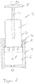
Figur 1 : Ampulleneinheit mit Adapter, Innengewinde -
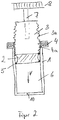
Figur 2 : Ampulleneinheit mit Mutter als Adapter -
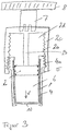
Figur 3 : Ampulleneinheit mit Adapter, Außengewinde -
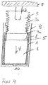
Figur 4 . Ampulleneinheit, Adapter als Teil des Gehäuses - In
Figur 1 ist eine Ampulle 1 zu sehen, die in einem Adapter 4 aufgenommen und mit einer Kolbeneinheit 2 verbunden ist. Die Ampulle 1 weist eine distale Öffnung 10 zur Abgabe des Ampulleninhalts aus der Fluidkammer 6 und eine proximale Öffnung, zur Aufnahme und Führung einer Verdrängungseinheit, hier die Kolbeneinheit 2 auf. In das proximale Ende der Ampulle 1 reicht ein Abschnitt des Adapters 4 mit einem an diesem Abschnitt des Adapters 4 gebildeten Gewinde 4a, im Sinne dieser Beschreibung einem Innengewinde, hinein. In diesem ersten Ausführungsbeispiel reicht das Gewinde 4a über den gesamten in der Ampulle 1 liegenden Abschnitt bis zu seinem proximalsten Ende. Das Gewinde 4a kann aber auch nur an einem Teil des in die Ampulle 1 reichenden Adapterabschnitts angeformt sein, beispielsweise weiter in die distale Richtung verschoben. Wichtig ist, dass der Adapter 4 die Ampulle verdreh- und verschiebesicher hält. Das heißt, der Adapter 4 bildet beispielsweise eine weitestgehend starre Hülse, in die die Ampulle 1 eingeschoben werden kann, mit einem distalen Ende, das das distale Ende der Ampulle 1 umgreift, und einem proximalen Ende, das das proximale Ende der Ampulle 1 umgreift. Im gezeigten Ausführungsbeispiel kann die Ampulle 1 beispielsweise von der distalen Seite in den Adapter 4 eingeführt werden. Dabei weist der Adapter 4 an seinem distalen Ende beispielsweise keine geschlossenen Zylinderform auf, sondern Elemente, die sich beim Einführen der Ampulle 1 elastisch nach außen biegen und bei vollständig eingeführter Ampulle 1, das heißt, wenn das proximale äußere Ende der Ampulle 1 am proximalen inneren Ende des Adapters 4 anliegt, in ihre Ausgangslage zurückfedern und so die Ampulle 1 verschiebesicher halten. Das proximale innere Ende des Adapters wird im gezeigten Ausführungsbeispiel durch das proximale Ende des Hohlraumes definiert, den der Adapter 4 an seinem proximalen Ende durch das Umschlagen um das proximale Ampullenende bildet. - Zum Ausschütten des Inhalts der Fluidkammer 6 ist in
Figur 1 eine mit dem Adapter 4 zusammenwirkende Kolbeneinheit 2 dargestellt. Diese Kolbeneinheit 2 besteht aus einem Zentralkolben 2b, der einen Außendurchmesser aufweist, der im Wesentlichen dem Innendurchmesser der Ampulle 1 entspricht. An seinem vordersten, distalen Ende weist der Zentralkolben eine Dichtung 5 auf, die den Inhalt der Ampulle 1 daran hindert, bei der Ausschüttung nach hinten aus der Ampulle 1 auszutreten. Diese Dichtung 5 kann fest mit dem Zentralkolben 2b verbunden sein, bevorzugt dient sie aber bereits bei der Bereitstellung der Ampulle 1 als proximale Abdichtung und wird durch die Kolbeneinheit 2 bei der Ausschüttung in die distale Richtung mitgenommen. - Zur Ausschüttung ist die Kolbeneinheit 2 mit einem Antrieb 7, 8 verbunden, der die Kolbeneinheit 2 in Drehung um ihre Drehachse versetzt, wodurch sich die Kolbeneinheit 2 in der Gewindeverbindung 2a, 4a in die Ampulle 1 schraubt und die Ausschüttung des Inhalts der Ampulle 1 durch die Öffnung 10 bewirkt. Eine rein lineare Bewegung des Zentralkolbens 2b in die Ausschüttrichtung V ist nicht möglich. Nur durch eine Drehung der Kolbeneinheit 2 kann der Zentralkolben 2b über das Gewinde 4a und das Gegengewinde 2a in die Ampulle 1 geschraubt werden. Um in die Vortriebsrichtung V eine Distanz x, die einer Ausschüttungsmenge y entspricht zurückzulegen, muss der sich in die Ampulle 1 schraubende Zentralkolben 2b daher einen größeren Laufweg zurücklegen, als dies bei einer rein linearen Bewegung der Fall wäre. Dies führt vorteilhafter Weise dazu, dass eine Haftreibung zwischen Ampulleninnenwand und Kolbenaußenseite sicher in eine Gleitreibung während der Bewegung des Kolbens überführt wird. Dadurch wird auch bei der wiederholten Abgabe kleiner oder kleinster Mengen von Fluid die vorgegebene Ausschüttmenge immer mit großer Zuverlässigkeit erreicht. Eine Verfälschung der einzelnen Ausschüttmenge durch Slipstick-Probleme oder eine lange Dehnungskette des Systems wird weitestgehend ausgeschlossen.
-
Figur 2 zeigt ein zweites Ausführungsbeispiel der Ampulleneinheit. Mit der Ampulle 1 ist ein Adapter 4, in Form einer Mutter mit Innengewinde fest verbunden. Fest heißt in diesem Zusammenhang, dass sich die Mutter bzw. der Adapter 4 relativ zur Ampulle 1 weder linear noch rotativ bewegen kann. Dies kann durch eine geeignete Klebe- oder Schweißverbindung erreicht werden, ebenso gut aber auch durch eine entsprechende Ausformung des Ampullenendes, in das der Adapter 4 formschlüssig und gesichert gegen jegliche Relativbewegung zur Ampulleneinheit 1 gehalten wird. - Der Kolben 2 ist im Ausführungsbeispiel an seiner Außenseite konkav geformt und weist an dem oberen und unteren Ende umlaufend je eine Dichtung 5 auf. Er kann als unabhängiges Einzelteil geformt sein und bereits im Auslieferzustand der Ampulle 1 als rückwärtige Dichtung dienen. In diesem Fall weist er an seiner proximalen, das heißt, der Vortriebsrichtung V entgegengesetzten Seite, Verbindungselemente auf, mit der er mit einer Kolbenstange 3 verdrehsicher verbunden werden kann. Verdrehsicher soll heißen, dass der Kolben 2 im verbundenen Zustand mit der Kolbenstange 3 jeder Drehbewegung der Kolbenstange mitmacht, zumindest jede Drehbewegung, mit der sich der Kolben 2 in distale Richtung in die Ampulle hineinschraubt und Fluid aus der Fluidkammer 10 durch die Öffnung 10 verdrängt.
- Die Kolbenstange 3 weist ein Außengewinde 3a auf, das ein Gegengewinde zum Innengewinde des Adapters 4 ist. Das heißt, die Gewindestange 3 kann sich mit ihrem Gewinde 3a in das Gewinde 4a des Adapters 4 drehen und schraubt sich dadurch in Vortriebsrichtung V in die Ampulle 1 hinein. Die Kolbenstange 3 kann direkt oder über einen nicht gezeigten Stutzen über ein Antriebselement 7 mit einem Zahnrad 8 verbunden sein, dass von einem Motor oder händisch angetrieben wird und dadurch den Kolben 2 in die Vortriebsrichtung V schraubt.
- Ein drittes Ausführungsbeispiel zeigt
Figur 3 . Hier ist die Ampulle 1 in einem Adapter 4 gehalten, der sie teilweise umgibt, so dass sich der Adapter 4 relativ zur Ampulle 1 weder linear noch rotativ bewegen kann. Dazu kann der Adapter 4 mit der Ampulle 1 formschlüssig verbunden, verklebt, verschweiß oder verschrumpft sein. Wichtig ist einzig und allein die weitestgehend starre Verbindung der beiden Teile, die keine Relativbewegung zwischen Ampulle 1 und Adapter 4 zulässt. - Der Adapter 4 weist in seinem hinteren, proximalen Bereich ein Außengewinde im Sinne der Beschreibung auf. Mit diesem in Gewindeeingriff steht eine Kolbeneinheit, die wie die Kolbeneinheit der
Figur 1 ausgebildet ist und für die das dort gesagte entsprechend gilt. - Ein weiteres Ausführungsbeispiel der Erfindung zeigt schließlich die
Figur 4 . Der erfindungsgemäße Adapter 4 wird hier durch ein Gehäuse 9 gebildet. Dieses Gehäuse 9 kann beispielsweise das Gehäuse des Verabreichungsgerätes sein, oder das Gehäuse einer Untereinheit des Verabreichungsgerätes, die als Gesamtheit in das Verabreichungsgerät eingesetzt wird. Das an der Innenseite der Gehäusewand angeformte Gewinde 9a liegt oberhalb einer in das Gehäuse eingesetzten Ampulle 1. Die Ampulle 1 ist in dem Gehäuse 9 verdreh- und verschiebesichersicher gehalten. Mit dem Innengewinde 9a des Gehäuses 9 ist das Außengewinde 2a einer Kolbeneinheit 2 in Gewindeeingriff. Durch Drehung der Kolbeneinheit 2 um ihre Drehachse, wird die Kolbeneinheit 2 in Vortriebsrichtung V in die Ampulle hineingeschraubt und bewirkt eine Ausschüttung aus der Fluidkammer 6 durch die Öffnung 10. Zur detaillierten Beschreibung wird aufFigur 2 verwiesen. Das dort zur Zusammenwirkung von Adapter 4 und Kolbenstange 3 gesagt gilt ebenso für das Ausführungsbeispiel derFigur 4 . -
- 1
- Ampulle
- 1a
- Ampullengewinde
- 2
- Kolben / Kolbeneinheit
- 2a
- Kolbengewinde
- 2b
- Zentralkolben
- 2c
- Kolbenhülse
- 2d
- Schlitz
- 3
- Kolbenstange
- 3a
- Kolbenstangengewinde
- 4
- Adapter
- 4a
- Adaptergewinde
- 5
- Dichtung
- 6
- Fluidkammer
- 7
- Antriebselement
- 8
- Zahnrad
- 9
- Gehäuse
- 9a
- Gehäusegewinde
- 10
- Öffnung
- V
- Vortriebsrichtung
Claims (15)
- Ampulleneinheit für ein Verabreichungsgerät, insbesondere ein Injektionsgerät oder eine Injektionsspritze, wobei die Ampulleneinheit zur wiederholten reproduzierbaren Abgabe von kleinen Mengen eines flüssigen Medikaments ausgebildet ist, wobei das flüssige Medikament Insulin oder ein Hormonpräparat umfasst, umfassend
eine Ampulle (1) mit einem distalen Ende mit einer Öffnung (10) zur Abgabe eines fluiden Produkts, und einem proximalen Ende mit einer Öffnung zur Aufnahme einer Verdrängungskörpereinheit,
einen Adapter (4), der mit der Ampulle (1) derart durch Verklebung, Verschweissung oder andere Verbindungen verdreh- und verschiebesicher verbunden ist, derart dass gesichert ist, dass die Ampulle sich zum Adapter relativ weder in Längsrichtung noch in Umfangsrichtung bewegen kann, und
eine Kolbeneinheit (2, 3), welche die Verdrängungskörpereinheit bildet, wobei
der Adapter (4) mit einem Gewinde (4a) versehen ist, und an der Kolbeneinheit (2, 3) ein Gegengewinde (2a, 3a) zum Gewinde (4a) des Adapters (4) gebildet ist, das mit diesem in Gewindeeingriff ist,
dadurch gekennzeichnet, dass
die Kolbeneinheit (2, 3) mit einem Antrieb (7, 8) verbunden ist, der ausgebildet ist, die Kolbeneinheit (2, 3) um eine Drehachse in Drehung zu versetzen, wodurch sich die Kolbeneinheit (2, 3) aufgrund des Gewindeeingriffs zwischen dem Gewinde (4a) des Adapters (4) und dem Gegengewinde (2a, 3a) der Kolbeneinheit (2, 3) in die Ampulle schraubt und die Abgabe des fluiden Produkts durch die Öffnung (10) bewirkt. - Ampulleneinheit nach einem der vorgehenden Ansprüche, wobei die Gewindesteigung der Gewinde (4a) und Gegengewinde (2a; 3a) ≤ 2 mm/U ist.
- Ampulleneineinheit nach einem der vorgehenden Ansprüche, wobei die Gewindesteigung im Bereich von 0,5 mm/U ≤ 2 mm/U liegt.
- Ampulleneinheit nach einem der vorgehenden Ansprüche, wobei es sich bei dem Gewinde (4a) um ein Innengewinde und bei dem Gegengewinde (2a; 3a) um ein Aussengewinde handelt oder vice versa.
- Ampulleneinheit nach einem der Ansprüche 1 bis 4, wobei eine Mutter, die fest mit dem proximalen Ende der Ampulle (1) verbunden ist, den Adapter (4) bildet.
- Ampulleneinheit nach einem der Ansprüche 1 bis 4, wobei der Adapter (4) die Ampulle (1) wenigstens teilweise umgibt und unlösbar mit der Ampulle (1) verbunden ist.
- Ampulleneinheit nach Anspruch 6, wobei der Adapter (4) auf die Ampulle (1) aufgespritzt oder aufgeschrumpft ist.
- Ampulleneinheit nach einem der Ansprüche 1 bis 7, wobei ein Kolben (2) die Kolbeneinheit bildet.
- Ampulleneinheit nach einem der Ansprüche 1 bis 7, wobei die Kolbeneinheit (2, 3) aus einem Kolben (2) und einer Kolbenstange (3) besteht und das Gegengewinde (2a; 3a) am Kolben (2) und/oder an der Kolbenstange (3) gebildet ist.
- Ampulleneinheit nach Anspruch 9, dadurch gekennzeichnet, dass der Kolben (2) mit der Kolbenstange (3) derart verdrehsicher verbunden ist, dass der Kolben jede Drehbewegung der Kolbenstange mitmacht, mit der sich der Kolben in distaler Richtung in die Ampulle (1) hineinschraubt.
- Ampulleneinheit nach Anspruch 9 oder 10, dadurch gekennzeichnet, dass die Aussenseite des Kolbens (2) konkav geformt ist, und der Kolben an seinem distalen und an seinem proximalen Ende je eine Dichtung (5) aufweist.
- Ampulleneinheit nach einem der Ansprüche 9 bis 11, wobei der Kolben (2) mit der Kolbenstange (3) lösbar, beispielsweise über eine Schraub- oder Steckverbindung, verbunden ist.
- Ampulleneinheit nach einem der Ansprüche 9 bis 11, wobei der Kolben (2) mit der Kolbenstange (3) unlösbar verbunden ist.
- Ampulleneinheit nach Anspruch 13, wobei der Kolben (2) und die Kolbenstange (3) einstückig, vorzugsweise aus Kunststoff, gebildet sind.
- Ampulleneinheit nach einem der vorgehenden Ansprüche, wobei der Kolben (2) oder die Kolbenstange (3) mit einem Antrieb, der den Kolben (2) und die Kolbenstange (3) rotativ antreibt, verbindbar sind.
Priority Applications (4)
| Application Number | Priority Date | Filing Date | Title |
|---|---|---|---|
| EP07118924.5A EP2050477B1 (de) | 2007-10-19 | 2007-10-19 | Ampulleneinheit mit Adapter |
| DK07118924.5T DK2050477T3 (en) | 2007-10-19 | 2007-10-19 | Ampoule unit with adapter |
| PCT/EP2008/008677 WO2009049858A1 (en) | 2007-10-19 | 2008-10-14 | Ampoule unit with thread |
| US12/762,828 US9108004B2 (en) | 2007-10-19 | 2010-04-19 | Ampoule unit with thread |
Applications Claiming Priority (1)
| Application Number | Priority Date | Filing Date | Title |
|---|---|---|---|
| EP07118924.5A EP2050477B1 (de) | 2007-10-19 | 2007-10-19 | Ampulleneinheit mit Adapter |
Publications (2)
| Publication Number | Publication Date |
|---|---|
| EP2050477A1 EP2050477A1 (de) | 2009-04-22 |
| EP2050477B1 true EP2050477B1 (de) | 2018-12-26 |
Family
ID=38885295
Family Applications (1)
| Application Number | Title | Priority Date | Filing Date |
|---|---|---|---|
| EP07118924.5A Active EP2050477B1 (de) | 2007-10-19 | 2007-10-19 | Ampulleneinheit mit Adapter |
Country Status (4)
| Country | Link |
|---|---|
| US (1) | US9108004B2 (de) |
| EP (1) | EP2050477B1 (de) |
| DK (1) | DK2050477T3 (de) |
| WO (1) | WO2009049858A1 (de) |
Families Citing this family (16)
| Publication number | Priority date | Publication date | Assignee | Title |
|---|---|---|---|---|
| EP2050477B1 (de) | 2007-10-19 | 2018-12-26 | F.Hoffmann-La Roche Ag | Ampulleneinheit mit Adapter |
| CA2771159A1 (en) | 2009-08-27 | 2011-03-03 | Sanofi-Aventis Deutschland Gmbh | Injector device |
| CA3042909C (en) * | 2010-06-18 | 2021-04-13 | Becton, Dickinson And Company | Adjustable dose setting plunger for syringe |
| GB201015799D0 (en) | 2010-09-21 | 2010-10-27 | Owen Mumford Ltd | Autoinjectors |
| IT1403866B1 (it) * | 2010-09-30 | 2013-11-08 | Ungaro | Dosatore multiuso per materiale fluido o in pasta |
| PL3003440T3 (pl) * | 2013-06-05 | 2021-07-19 | Injecto Group A/S | Tłok do stosowania ze strzykawką o określonym stosunku wymiarowym konstrukcji uszczelniającej |
| US9457153B2 (en) * | 2014-08-29 | 2016-10-04 | Vascular Insights Llc | Syringe accessory |
| DE102014217773A1 (de) | 2014-09-05 | 2016-03-10 | Vetter Pharma-Fertigung GmbH & Co. KG | Pen |
| US20170056916A1 (en) * | 2015-08-29 | 2017-03-02 | Malic Bedford | Silicon ball in a glass tube advanced by threaded rod dispensing micro amounts of oils or other materials |
| CN106540360B (zh) * | 2016-11-07 | 2020-03-20 | 青岛市肿瘤医院 | 自废型一次性注射器 |
| JP6764319B2 (ja) * | 2016-11-16 | 2020-09-30 | Phcホールディングス株式会社 | 薬剤注入装置 |
| EP3621678B1 (de) | 2017-05-11 | 2021-07-07 | Novo Nordisk A/S | Automatische injektionsvorrichtung mit rotationsstoppmechanismus |
| CN110507879A (zh) * | 2018-05-22 | 2019-11-29 | 佛山市嘉懿行农业科技有限公司 | 一种预充注射装置 |
| CH715144A1 (fr) * | 2018-07-02 | 2020-01-15 | Edelweiss Dr Ag | Dispositif d’extrusion et système de distribution de composite. |
| CN114306816B (zh) * | 2021-12-20 | 2023-11-10 | 中山大学附属第三医院(中山大学肝脏病医院) | 一种细胞制剂贮存注射器 |
| US12246906B2 (en) * | 2022-01-31 | 2025-03-11 | Paulo Roberto Jannotti Newlands | Ecologically sustainable dispenser |
Citations (1)
| Publication number | Priority date | Publication date | Assignee | Title |
|---|---|---|---|---|
| US5059179A (en) * | 1989-05-15 | 1991-10-22 | David Quatrochi | Non-reusable syringe assembly |
Family Cites Families (13)
| Publication number | Priority date | Publication date | Assignee | Title |
|---|---|---|---|---|
| US2165597A (en) * | 1936-09-14 | 1939-07-11 | Sr Frederick Widoe | Method for forming dentures |
| US2475939A (en) * | 1946-07-12 | 1949-07-12 | Applezweig Norman | Cartridge syringe |
| US3128765A (en) * | 1962-07-17 | 1964-04-14 | American Home Prod | Hypodermic syringe and dose dispenser |
| DE7603096U1 (de) | 1976-02-04 | 1976-08-19 | Espe Pharm Praep | Vorrichtung zur dosierten Abgabe viskoser Massen |
| US4312343A (en) * | 1979-07-30 | 1982-01-26 | Leveen Harry H | Syringe |
| US4583974A (en) * | 1984-04-04 | 1986-04-22 | Kokernak Denis T | Syringe for balloon dilation catheters |
| US5618273A (en) * | 1995-03-27 | 1997-04-08 | Ultradent Product, Inc. | Syringe apparatus with threaded plunger for delivering tooth composites and other solid yet pliable materials |
| US7018365B2 (en) | 1999-05-21 | 2006-03-28 | Micro Therapeutics, Inc. | Threaded syringe with quick stop |
| US6571992B2 (en) | 2001-01-12 | 2003-06-03 | Dentsply Research & Development Corp. | Dispensing syringe |
| JP4405802B2 (ja) * | 2001-10-16 | 2010-01-27 | メディカル・インスティル・テクノロジーズ・インコーポレイテッド | 計量された量の物質を供給するための、密閉チャンバ及び一方向弁を備えたディスペンサ |
| US6955716B2 (en) | 2002-03-01 | 2005-10-18 | American Dental Association Foundation | Self-hardening calcium phosphate materials with high resistance to fracture, controlled strength histories and tailored macropore formation rates |
| EP1752172A1 (de) | 2005-08-12 | 2007-02-14 | F.Hoffmann-La Roche Ag | Antriebsvorrichtung für eine Infusionspumpe |
| EP2050477B1 (de) | 2007-10-19 | 2018-12-26 | F.Hoffmann-La Roche Ag | Ampulleneinheit mit Adapter |
-
2007
- 2007-10-19 EP EP07118924.5A patent/EP2050477B1/de active Active
- 2007-10-19 DK DK07118924.5T patent/DK2050477T3/en active
-
2008
- 2008-10-14 WO PCT/EP2008/008677 patent/WO2009049858A1/en not_active Ceased
-
2010
- 2010-04-19 US US12/762,828 patent/US9108004B2/en active Active
Patent Citations (1)
| Publication number | Priority date | Publication date | Assignee | Title |
|---|---|---|---|---|
| US5059179A (en) * | 1989-05-15 | 1991-10-22 | David Quatrochi | Non-reusable syringe assembly |
Also Published As
| Publication number | Publication date |
|---|---|
| DK2050477T3 (en) | 2019-04-15 |
| US20110106018A1 (en) | 2011-05-05 |
| US9108004B2 (en) | 2015-08-18 |
| WO2009049858A1 (en) | 2009-04-23 |
| EP2050477A1 (de) | 2009-04-22 |
Similar Documents
| Publication | Publication Date | Title |
|---|---|---|
| EP2050477B1 (de) | Ampulleneinheit mit Adapter | |
| EP1519766B1 (de) | Produktausschüttvorrichtung mit kolbenstangen-eilrücksetzung | |
| DE10232410B4 (de) | Verabreichungsgerät mit Dosisanzeige | |
| DE69404831T2 (de) | Vorrichtung und verfahren zur injektion von medikamenten | |
| DE60021425T2 (de) | Dosierungsbegrenzer | |
| DE69016982T2 (de) | Tragbares Medikamentenabgabegerät mit einer einen konischen Zylinder aufweisenden Pumpe. | |
| DE10351596B4 (de) | Autoinjektor mit variabler Dosis | |
| EP1568388B2 (de) | Autoinjektionsgerät | |
| DE60204422T3 (de) | Automatische einspritzeinheit mit rücksetzeigenschaft | |
| EP2396237B1 (de) | Austragvorrichtung mit tube | |
| EP0373321B1 (de) | Wiederverwendbares Injektionsgerät zur Abgabe einer vorwählbaren Dosis | |
| DE69302625T2 (de) | Medikamentenspender | |
| DD283332A5 (de) | Dosiervorrichtung zum dosieren einer anzahl abgemessener fluessigkeitsmengen, wie insulinpraeparate | |
| EP1414506A2 (de) | Reservoirmodul mit Kolbenstange | |
| DE10163325A1 (de) | Verriegelungssperre für eine Verbindung von Gehäuseabschnitten eines Verabreichungsgeräts | |
| WO1998011927A1 (de) | Abtriebsglied für den vorschub eines stopfens einer spritzampulle und stopfen hierzu | |
| DE10163326A1 (de) | Verabreichungsgerät mit Dosiervorrichtung | |
| WO2002005878A1 (de) | Vorratsbehältnis mit einer dosiereinrichtung zur dosierten abgabe eines injizierbaren produkts an ein injektionsgerät | |
| DE20112501U1 (de) | Verriegelungssperre für eine Verbindung von Gehäuseteilen eines Injektions- oder Infusionsgeräts | |
| EP3142727A1 (de) | Spindelvorrichtung für einen kolben eines reservoirs mit medikamentenfluid | |
| DE10232158A1 (de) | Verabreichungsgerät mit rückzugsgesperrter Kolbenstange | |
| DE102006018827A1 (de) | Applikator mit auswechselbarem Behälter | |
| EP1883387B1 (de) | Behälter für zu verabreichende flüssige Medikamente | |
| DE60222426T2 (de) | Kartuschenlose multidosis-injektionsvorrichtung | |
| DE102013201460A1 (de) | Composite-Kapsel und Verfahren zum Ausbringen einer Dentalmasse |
Legal Events
| Date | Code | Title | Description |
|---|---|---|---|
| PUAI | Public reference made under article 153(3) epc to a published international application that has entered the european phase |
Free format text: ORIGINAL CODE: 0009012 |
|
| AK | Designated contracting states |
Kind code of ref document: A1 Designated state(s): AT BE BG CH CY CZ DE DK EE ES FI FR GB GR HU IE IS IT LI LT LU LV MC MT NL PL PT RO SE SI SK TR |
|
| AX | Request for extension of the european patent |
Extension state: AL BA HR MK RS |
|
| 17P | Request for examination filed |
Effective date: 20090512 |
|
| 17Q | First examination report despatched |
Effective date: 20090610 |
|
| AKX | Designation fees paid |
Designated state(s): AT BE BG CH CY CZ DE DK EE ES FI FR GB GR HU IE IS IT LI LT LU LV MC MT NL PL PT RO SE SI SK TR |
|
| REG | Reference to a national code |
Ref country code: DE Ref legal event code: R079 Ref document number: 502007016534 Country of ref document: DE Free format text: PREVIOUS MAIN CLASS: A61M0005240000 Ipc: A61M0005315000 |
|
| RIC1 | Information provided on ipc code assigned before grant |
Ipc: A61M 5/315 20060101AFI20160601BHEP Ipc: A61M 5/24 20060101ALI20160601BHEP Ipc: A61M 5/31 20060101ALI20160601BHEP |
|
| RAP1 | Party data changed (applicant data changed or rights of an application transferred) |
Owner name: F.HOFFMANN-LA ROCHE AG Owner name: ROCHE DIABETES CARE GMBH |
|
| STAA | Information on the status of an ep patent application or granted ep patent |
Free format text: STATUS: EXAMINATION IS IN PROGRESS |
|
| GRAP | Despatch of communication of intention to grant a patent |
Free format text: ORIGINAL CODE: EPIDOSNIGR1 |
|
| STAA | Information on the status of an ep patent application or granted ep patent |
Free format text: STATUS: GRANT OF PATENT IS INTENDED |
|
| INTG | Intention to grant announced |
Effective date: 20180725 |
|
| GRAS | Grant fee paid |
Free format text: ORIGINAL CODE: EPIDOSNIGR3 |
|
| GRAA | (expected) grant |
Free format text: ORIGINAL CODE: 0009210 |
|
| STAA | Information on the status of an ep patent application or granted ep patent |
Free format text: STATUS: THE PATENT HAS BEEN GRANTED |
|
| AK | Designated contracting states |
Kind code of ref document: B1 Designated state(s): AT BE BG CH CY CZ DE DK EE ES FI FR GB GR HU IE IS IT LI LT LU LV MC MT NL PL PT RO SE SI SK TR |
|
| REG | Reference to a national code |
Ref country code: GB Ref legal event code: FG4D Free format text: NOT ENGLISH |
|
| REG | Reference to a national code |
Ref country code: CH Ref legal event code: EP |
|
| REG | Reference to a national code |
Ref country code: AT Ref legal event code: REF Ref document number: 1080547 Country of ref document: AT Kind code of ref document: T Effective date: 20190115 |
|
| REG | Reference to a national code |
Ref country code: DE Ref legal event code: R096 Ref document number: 502007016534 Country of ref document: DE |
|
| REG | Reference to a national code |
Ref country code: IE Ref legal event code: FG4D Free format text: LANGUAGE OF EP DOCUMENT: GERMAN |
|
| REG | Reference to a national code |
Ref country code: DK Ref legal event code: T3 Effective date: 20190408 |
|
| REG | Reference to a national code |
Ref country code: NL Ref legal event code: FP |
|
| PG25 | Lapsed in a contracting state [announced via postgrant information from national office to epo] |
Ref country code: LV Free format text: LAPSE BECAUSE OF FAILURE TO SUBMIT A TRANSLATION OF THE DESCRIPTION OR TO PAY THE FEE WITHIN THE PRESCRIBED TIME-LIMIT Effective date: 20181226 Ref country code: BG Free format text: LAPSE BECAUSE OF FAILURE TO SUBMIT A TRANSLATION OF THE DESCRIPTION OR TO PAY THE FEE WITHIN THE PRESCRIBED TIME-LIMIT Effective date: 20190326 Ref country code: LT Free format text: LAPSE BECAUSE OF FAILURE TO SUBMIT A TRANSLATION OF THE DESCRIPTION OR TO PAY THE FEE WITHIN THE PRESCRIBED TIME-LIMIT Effective date: 20181226 Ref country code: FI Free format text: LAPSE BECAUSE OF FAILURE TO SUBMIT A TRANSLATION OF THE DESCRIPTION OR TO PAY THE FEE WITHIN THE PRESCRIBED TIME-LIMIT Effective date: 20181226 |
|
| REG | Reference to a national code |
Ref country code: LT Ref legal event code: MG4D |
|
| PG25 | Lapsed in a contracting state [announced via postgrant information from national office to epo] |
Ref country code: SE Free format text: LAPSE BECAUSE OF FAILURE TO SUBMIT A TRANSLATION OF THE DESCRIPTION OR TO PAY THE FEE WITHIN THE PRESCRIBED TIME-LIMIT Effective date: 20181226 Ref country code: GR Free format text: LAPSE BECAUSE OF FAILURE TO SUBMIT A TRANSLATION OF THE DESCRIPTION OR TO PAY THE FEE WITHIN THE PRESCRIBED TIME-LIMIT Effective date: 20190327 |
|
| PG25 | Lapsed in a contracting state [announced via postgrant information from national office to epo] |
Ref country code: ES Free format text: LAPSE BECAUSE OF FAILURE TO SUBMIT A TRANSLATION OF THE DESCRIPTION OR TO PAY THE FEE WITHIN THE PRESCRIBED TIME-LIMIT Effective date: 20181226 Ref country code: PT Free format text: LAPSE BECAUSE OF FAILURE TO SUBMIT A TRANSLATION OF THE DESCRIPTION OR TO PAY THE FEE WITHIN THE PRESCRIBED TIME-LIMIT Effective date: 20190426 Ref country code: CZ Free format text: LAPSE BECAUSE OF FAILURE TO SUBMIT A TRANSLATION OF THE DESCRIPTION OR TO PAY THE FEE WITHIN THE PRESCRIBED TIME-LIMIT Effective date: 20181226 Ref country code: PL Free format text: LAPSE BECAUSE OF FAILURE TO SUBMIT A TRANSLATION OF THE DESCRIPTION OR TO PAY THE FEE WITHIN THE PRESCRIBED TIME-LIMIT Effective date: 20181226 |
|
| PG25 | Lapsed in a contracting state [announced via postgrant information from national office to epo] |
Ref country code: IS Free format text: LAPSE BECAUSE OF FAILURE TO SUBMIT A TRANSLATION OF THE DESCRIPTION OR TO PAY THE FEE WITHIN THE PRESCRIBED TIME-LIMIT Effective date: 20190426 Ref country code: SK Free format text: LAPSE BECAUSE OF FAILURE TO SUBMIT A TRANSLATION OF THE DESCRIPTION OR TO PAY THE FEE WITHIN THE PRESCRIBED TIME-LIMIT Effective date: 20181226 Ref country code: RO Free format text: LAPSE BECAUSE OF FAILURE TO SUBMIT A TRANSLATION OF THE DESCRIPTION OR TO PAY THE FEE WITHIN THE PRESCRIBED TIME-LIMIT Effective date: 20181226 Ref country code: EE Free format text: LAPSE BECAUSE OF FAILURE TO SUBMIT A TRANSLATION OF THE DESCRIPTION OR TO PAY THE FEE WITHIN THE PRESCRIBED TIME-LIMIT Effective date: 20181226 |
|
| REG | Reference to a national code |
Ref country code: DE Ref legal event code: R097 Ref document number: 502007016534 Country of ref document: DE |
|
| PLBE | No opposition filed within time limit |
Free format text: ORIGINAL CODE: 0009261 |
|
| STAA | Information on the status of an ep patent application or granted ep patent |
Free format text: STATUS: NO OPPOSITION FILED WITHIN TIME LIMIT |
|
| 26N | No opposition filed |
Effective date: 20190927 |
|
| PG25 | Lapsed in a contracting state [announced via postgrant information from national office to epo] |
Ref country code: SI Free format text: LAPSE BECAUSE OF FAILURE TO SUBMIT A TRANSLATION OF THE DESCRIPTION OR TO PAY THE FEE WITHIN THE PRESCRIBED TIME-LIMIT Effective date: 20181226 |
|
| PG25 | Lapsed in a contracting state [announced via postgrant information from national office to epo] |
Ref country code: TR Free format text: LAPSE BECAUSE OF FAILURE TO SUBMIT A TRANSLATION OF THE DESCRIPTION OR TO PAY THE FEE WITHIN THE PRESCRIBED TIME-LIMIT Effective date: 20181226 |
|
| PG25 | Lapsed in a contracting state [announced via postgrant information from national office to epo] |
Ref country code: MC Free format text: LAPSE BECAUSE OF FAILURE TO SUBMIT A TRANSLATION OF THE DESCRIPTION OR TO PAY THE FEE WITHIN THE PRESCRIBED TIME-LIMIT Effective date: 20181226 |
|
| PG25 | Lapsed in a contracting state [announced via postgrant information from national office to epo] |
Ref country code: LU Free format text: LAPSE BECAUSE OF NON-PAYMENT OF DUE FEES Effective date: 20191019 |
|
| REG | Reference to a national code |
Ref country code: BE Ref legal event code: MM Effective date: 20191031 |
|
| PG25 | Lapsed in a contracting state [announced via postgrant information from national office to epo] |
Ref country code: BE Free format text: LAPSE BECAUSE OF NON-PAYMENT OF DUE FEES Effective date: 20191031 |
|
| PG25 | Lapsed in a contracting state [announced via postgrant information from national office to epo] |
Ref country code: IE Free format text: LAPSE BECAUSE OF NON-PAYMENT OF DUE FEES Effective date: 20191019 |
|
| REG | Reference to a national code |
Ref country code: AT Ref legal event code: MM01 Ref document number: 1080547 Country of ref document: AT Kind code of ref document: T Effective date: 20191019 |
|
| PG25 | Lapsed in a contracting state [announced via postgrant information from national office to epo] |
Ref country code: AT Free format text: LAPSE BECAUSE OF NON-PAYMENT OF DUE FEES Effective date: 20191019 |
|
| PG25 | Lapsed in a contracting state [announced via postgrant information from national office to epo] |
Ref country code: CY Free format text: LAPSE BECAUSE OF FAILURE TO SUBMIT A TRANSLATION OF THE DESCRIPTION OR TO PAY THE FEE WITHIN THE PRESCRIBED TIME-LIMIT Effective date: 20181226 |
|
| PG25 | Lapsed in a contracting state [announced via postgrant information from national office to epo] |
Ref country code: HU Free format text: LAPSE BECAUSE OF FAILURE TO SUBMIT A TRANSLATION OF THE DESCRIPTION OR TO PAY THE FEE WITHIN THE PRESCRIBED TIME-LIMIT; INVALID AB INITIO Effective date: 20071019 Ref country code: MT Free format text: LAPSE BECAUSE OF FAILURE TO SUBMIT A TRANSLATION OF THE DESCRIPTION OR TO PAY THE FEE WITHIN THE PRESCRIBED TIME-LIMIT Effective date: 20181226 |
|
| PGFP | Annual fee paid to national office [announced via postgrant information from national office to epo] |
Ref country code: DK Payment date: 20240919 Year of fee payment: 18 |
|
| PGFP | Annual fee paid to national office [announced via postgrant information from national office to epo] |
Ref country code: GB Payment date: 20240919 Year of fee payment: 18 |
|
| PGFP | Annual fee paid to national office [announced via postgrant information from national office to epo] |
Ref country code: FR Payment date: 20240919 Year of fee payment: 18 |
|
| PGFP | Annual fee paid to national office [announced via postgrant information from national office to epo] |
Ref country code: NL Payment date: 20240919 Year of fee payment: 18 |
|
| PGFP | Annual fee paid to national office [announced via postgrant information from national office to epo] |
Ref country code: IT Payment date: 20240919 Year of fee payment: 18 |
|
| PGFP | Annual fee paid to national office [announced via postgrant information from national office to epo] |
Ref country code: DE Payment date: 20240919 Year of fee payment: 18 |
|
| PGFP | Annual fee paid to national office [announced via postgrant information from national office to epo] |
Ref country code: CH Payment date: 20241101 Year of fee payment: 18 |