EP2050106B1 - Elektromagnetische stellvorrichtung - Google Patents
Elektromagnetische stellvorrichtung Download PDFInfo
- Publication number
- EP2050106B1 EP2050106B1 EP07786505A EP07786505A EP2050106B1 EP 2050106 B1 EP2050106 B1 EP 2050106B1 EP 07786505 A EP07786505 A EP 07786505A EP 07786505 A EP07786505 A EP 07786505A EP 2050106 B1 EP2050106 B1 EP 2050106B1
- Authority
- EP
- European Patent Office
- Prior art keywords
- contact elements
- support
- winding wires
- winding
- contact
- Prior art date
- Legal status (The legal status is an assumption and is not a legal conclusion. Google has not performed a legal analysis and makes no representation as to the accuracy of the status listed.)
- Not-in-force
Links
Images

Classifications
-
- H—ELECTRICITY
- H01—ELECTRIC ELEMENTS
- H01F—MAGNETS; INDUCTANCES; TRANSFORMERS; SELECTION OF MATERIALS FOR THEIR MAGNETIC PROPERTIES
- H01F7/00—Magnets
- H01F7/06—Electromagnets; Actuators including electromagnets
- H01F7/08—Electromagnets; Actuators including electromagnets with armatures
- H01F7/16—Rectilinearly-movable armatures
- H01F7/1638—Armatures not entering the winding
- H01F7/1646—Armatures or stationary parts of magnetic circuit having permanent magnet
-
- H—ELECTRICITY
- H01—ELECTRIC ELEMENTS
- H01F—MAGNETS; INDUCTANCES; TRANSFORMERS; SELECTION OF MATERIALS FOR THEIR MAGNETIC PROPERTIES
- H01F5/00—Coils
- H01F5/04—Arrangements of electric connections to coils, e.g. leads
-
- F—MECHANICAL ENGINEERING; LIGHTING; HEATING; WEAPONS; BLASTING
- F01—MACHINES OR ENGINES IN GENERAL; ENGINE PLANTS IN GENERAL; STEAM ENGINES
- F01L—CYCLICALLY OPERATING VALVES FOR MACHINES OR ENGINES
- F01L13/00—Modifications of valve-gear to facilitate reversing, braking, starting, changing compression ratio, or other specific operations
- F01L13/0015—Modifications of valve-gear to facilitate reversing, braking, starting, changing compression ratio, or other specific operations for optimising engine performances by modifying valve lift according to various working parameters, e.g. rotational speed, load, torque
- F01L13/0036—Modifications of valve-gear to facilitate reversing, braking, starting, changing compression ratio, or other specific operations for optimising engine performances by modifying valve lift according to various working parameters, e.g. rotational speed, load, torque the valves being driven by two or more cams with different shape, size or timing or a single cam profiled in axial and radial direction
- F01L2013/0052—Modifications of valve-gear to facilitate reversing, braking, starting, changing compression ratio, or other specific operations for optimising engine performances by modifying valve lift according to various working parameters, e.g. rotational speed, load, torque the valves being driven by two or more cams with different shape, size or timing or a single cam profiled in axial and radial direction with cams provided on an axially slidable sleeve
-
- H—ELECTRICITY
- H01—ELECTRIC ELEMENTS
- H01F—MAGNETS; INDUCTANCES; TRANSFORMERS; SELECTION OF MATERIALS FOR THEIR MAGNETIC PROPERTIES
- H01F27/00—Details of transformers or inductances, in general
- H01F27/02—Casings
- H01F27/022—Encapsulation
-
- H—ELECTRICITY
- H01—ELECTRIC ELEMENTS
- H01F—MAGNETS; INDUCTANCES; TRANSFORMERS; SELECTION OF MATERIALS FOR THEIR MAGNETIC PROPERTIES
- H01F7/00—Magnets
- H01F7/06—Electromagnets; Actuators including electromagnets
- H01F7/08—Electromagnets; Actuators including electromagnets with armatures
- H01F7/121—Guiding or setting position of armatures, e.g. retaining armatures in their end position
- H01F7/122—Guiding or setting position of armatures, e.g. retaining armatures in their end position by permanent magnets
Definitions
- the present invention relates to an electromagnetic actuator according to the preamble of claim 1.
- Such devices are well known and are used for a variety of purposes.
- the basic principle is that a piston-shaped control element, which has an inlet region for the intended setting task, is guided in a generally magnetically conductive housing as an armature between a stationary core region and a bearing element acting as a yoke and by means of an approximately provided in the core region electromagnet can be operated.
- the coil device comprises a plastic carrier, on which a coil winding is wound.
- the winding wires of the coil winding are guided to contact elements and electrically conductively connected thereto, wherein the contact elements serve for connection to an external power supply.
- the contact elements are usually part of an electrical connector.
- the adjusting element and / or the permanent magnet arrangement When resetting the adjusting element in the direction of the coil device, for example by energizing the coil winding, the adjusting element and / or the permanent magnet arrangement generally moves unrestrained against the plastic carrier and / or the core region fixedly connected to it, so that the plastic carrier is constantly exposed to vibrations during operation of the adjusting device is. This often happens
- the invention is therefore the object of developing a generic electromagnetic actuator such that their life is increased.
- the invention is based on the idea to store the connection between at least one winding wire and the associated contact element, preferably between all winding wires and the associated contact elements, mechanically vibration damped. Due to the vibration-damped mounting of the connections between the winding wires and the contact elements relative to the support of the coil winding (s) according to the characterizing part of claim 1, the vibrations are not transmitted or at least attenuated to the electrically conductive connection between the winding wires and the contact elements, whereby the mechanical load of the compounds mentioned is significantly reduced. This leads to From the DE 199 36 425 An electromagnetic actuator is known. In this winding wires associated contact pins are surrounded by an elastomeric member which isolates the pins from vibrations. in turn, that a tearing or destruction of the connection between the winding wires and the contact elements is avoided or at least delayed even with a continuous use of the electromagnetic actuator.
- a simple and effective way for vibration damping the connection between the winding wires and the contact elements is to arrange the compounds at least partially on or in an elastomeric pad, which is held according to the characterizing part of claim 1 to the carrier of the coil winding.
- a suitable elastomer for vibration damping is silicone. This can be applied to the contact elements and / or preferably to the carrier of the coil winding, in particular made of plastic, in a simple manner, preferably fully automatically within the scope of production of the electromagnetic actuator.
- each connection is damped with a separate elastomeric cushion according to the characterizing part of claim 1.
- the contact elements are designed as contact pins held on the carrier.
- the carrier is made of plastic, it is provided according to an advantageous development of the invention that in each case one end of a contact pin is encapsulated by the carrier or the carrier plastic. After curing the plastic sit the pins firmly on the carrier and are still electrically isolated due to the formation of the carrier made of plastic over other components.
- the contact elements are adjustable between a mounting position and an end position, preferably bendable.
- the contact elements In the assembly position, the contact elements with their free ends preferably spaced from the carrier, arranged so that the contact elements do not hinder application of one or more elastomeric pads on the carrier.
- the winding wires are electrically conductively fixed to the associated contact elements in the mounting position, whereupon the contact elements are bent with the winding wires fixed thereto in the direction of the elastomeric pads and thus stored vibration-damped relative to the support of the coil means.
- the winding wires are guided through a passage opening of the contact element. This makes it possible to guide the winding wires from the top of the contact elements to the outer side in the end position in order to solder or weld them there. Instead of fixing the winding wires to the contact elements by soldering or welding, these compounds can also be realized by gluing, in particular by applying a gluing point, in particular on the outside of the contact element.
- the winding wires are fully automatically in the mounting position of the contact elements, in particular the contact pins guided to the top of the contact elements and fixed there before the contact elements are transferred to the end position on the elastomeric pad.
- the contact elements preferably the contact pins, have a holding section whose end is anchored within the carrier and are additionally provided with an end-side, flat contact portion, which is suitable for fixing the winding wires and / or for contacting an external power connection.
- FIG. 1 an electromagnetic adjustment device 1 is shown, which interacts with an actuating partner, not shown, in particular a camshaft Hubumsciens actuated.
- the electromagnetic adjustment device 1 comprises a hollow cylindrical, magnetically conductive Bushing element 2, within which an elongated piston-shaped control element 3 is arranged.
- the actuator 3 passes through a non-rotatably mounted on this permanent magnet assembly 4, which consists of a central, cylindrical soft iron disk 5 and on both sides of this arranged permanent magnet 6a, 6b with a larger diameter, but smaller thickness.
- the adjusting element 3 is movably guided between a stationary core region 7 and a sleeve-shaped, acting as a yoke bearing element 8, wherein the bearing element 8 is sealingly guided in a correspondingly measured hollow cylindrical recess 9 of a support member 10, for example, a motor block section.
- the core area 7 is part of an in Fig. 1 not shown coil means (13) (see. Fig. 2 to 5 ), which is arranged in the left half of the drawing within the socket element 2 and acting on the adjusting element 3, in particular away from the core region 7, acts.
- the piston-shaped, guided within the bearing element 8 actuator 3 is made in two parts. It comprises a first actuating element part 3a, which is arranged in the region of the permanent magnet arrangement 4, and an axially adjacent second actuating element part 3b, which is guided inside the bearing element 8.
- the second actuating element part 3b comprises at the end an engagement region 11, which acting acting on the control partners, not shown.
- the two actuator elements 3a, 3b are positively, rotatably connected to each other and laser welded together at their ends.
- the positive connection is realized with axially interlocking connection sections 12a, 12b, over which a torque in the circumferential direction between the two actuating element parts 3a, 3b in the circumferential direction is transferable.
- the connecting portions 12a, 12b of the actuator parts 3a, 3b are arranged alternately in the circumferential direction.
- first actuator element 3a is made of soft iron and the right in the drawing plane, the engagement portion 11 comprehensive second actuator element 3b is formed of cold-formed austenite and therefore has a higher mechanical strength.
- the engagement region 11 projects beyond the bearing element 8 also in the retracted state of the actuating element 3 shown.
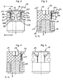
- FIG. 1 In the Fig. 1 from the sleeve element 2 concealed coil means 13, of the in Fig. 1 only a section of the metallic core region 7 is shown in FIG Fig. 2 to 5 shown in detail. It is in the Fig. 2 to 5 upper end face 14 of the coil device 13 in FIG Fig. 1 arranged pointing in the direction of the left end of the magnetic actuator 1.
- the coil device 13 consists of a carrier 15 made of plastic, which is formed substantially cylindrical.
- a central blind hole 16 within the carrier 15 of the metallic core portion 7 is added. With a radial distance to the core region 7, this is surrounded by a coil winding 17, wherein the coil winding 17 does not touch the core region 7 directly, but is separated from it by a peripheral wall 18 of the carrier 15.
- the coil winding 17 is supported on a radial circumferential shoulder 19 of the carrier 15 in the plane of the drawing down.
- contact elements 20, 21 are fixed on the support 15 .
- These each consist of a slender holding portion 20a, 21a, which is fixed in particular by encapsulation on the carrier 15 and in each case an end-side, flat contact portion 20b, 21b, which serves for contacting a power supply, not shown, in particular a corresponding plug-in element.
- a winding wire 22, 23 of the coil winding 17 is electrically conductively fixed, preferably glued.
- Fig. 3 the winding device 13 is shown in a mounting position.
- the contact elements 20, 21 designed as contact pins project away from the carrier 15 in the radial direction.
- the elastomeric pads 26, 27 are applied to the carrier 15, in particular by spraying or gluing.
- the winding wires 22, 23, in particular by gluing on the upper sides 28, 29 of the contact elements 20, 21 fixed.
- the winding wires 22, 23 preferably through a passage opening 30 guided to the top 28, 29 and fixed there, in particular glued.
- the contact elements 20, 21 are bent by about 90 ° (see. Fig. 4 ), so that they now point in the axial direction and rest on the elastomeric pads 26, 27 so as to be damped against vibration.
Landscapes
- Engineering & Computer Science (AREA)
- Power Engineering (AREA)
- Physics & Mathematics (AREA)
- Electromagnetism (AREA)
- Electromagnets (AREA)
- Valve Device For Special Equipments (AREA)
- Reciprocating, Oscillating Or Vibrating Motors (AREA)
Description
- Die vorliegende Erfindung betrifft eine elektromagnetische Stellvorrichtung gemäß dem Oberbegriff des Anspruchs 1.
- Derartige Vorrichtungen sind hinlänglich bekannt und werden für vielfältige Einsatzzwecke genutzt. Das Grundprinzip besteht darin, dass ein kolbenförmiges Stellelement, welches endseitig einen Eintrittsbereich für die vorgesehene Stellaufgabe aufweist, in einem in der Regel magnetisch leitfähigen Gehäuse als Anker zwischen einem stationären Kernbereich und einem als Joch wirkenden Lagerelement geführt ist und mittels eines etwa im Kernbereich vorgesehenen Elektromagneten betätigt werden kann.
- In der
DE 102 40 774 A1 der Anmelderin, welche als nächstliegender Stand der Technik angesehen wird, ist eine gattungsgemäße elektromagnetische Stellvorrichtung mit wesentlichen Elementen gezeigt. Bei der bekannten Stellvorrichtung umfasst die Spuleneinrichtung einen Kunststoffträger, auf den eine Spulenwicklung gewickelt ist. Üblicherweise sind die Wicklungsdrähte der Spulenwicklung zu Kontaktelementen geführt und mit diesen elektrisch leitend verbunden, wobei die Kontaktelemente zum Anschluss an eine externe Stromversorgung dienen. Die Kontaktelemente sind in der Regel Teil einer elektrischen Steckverbindung. Bei der Rückstellung des Stellelementes in Richtung Spuleneinrichtung, beispielsweise durch Bestromen der Spulenwicklung, verfährt das Stellelement und/oder die Permanentmagnetanordnung i.d.R. ungebremst gegen den Kunststoffträger und/oder den mit diesem fest verbundenen Kernbereich, so dass der Kunststoffträger bei dem Betrieb der Stellvorrichtung ständig Erschütterungen ausgesetzt ist. Hierdurch kommt es häufig - zu einem Abreißen der Verbindung zwischen den Wicklungsdrähten und den Kontaktelementen, was dazu führt, dass die Spuleneinrichtung und damit die gesamte elektromagnetische Stellvorrichtung ihre Funktionsfähigkeit verliert, was wiederum negative Auswirkungen auf die Funktionsfähigkeit des Stellpartners, beispielsweise eine Nockenwellen-Hubumschaltung eines Motors und damit auch die Funktionstüchtigkeit des Motors selbst hat.
- Der Erfindung liegt daher die Aufgabe zugrunde, eine gattungsgemäße elektromagnetische Stellvorrichtung derart weiterzubilden, dass deren Standzeit erhöht ist.
- Diese Aufgabe wird mit den Merkmalen des Anspruchs 1 gelöst.
- Vorteilhafte Weiterbildungen der Erfindung sind in den Unteransprüchen angegeben.
- Der Erfindung liegt der Gedanke zugrunde, die Verbindung zwischen mindestens einem Wicklungsdraht und dem dazugehörigen Kontaktelement, vorzugsweise zwischen sämtlichen Wicklungsdrähten und den zugehörigen Kontaktelementen, mechanisch schwingungsgedämpft zu lagern. Durch die schwingungsgedämpfte Lagerung der Verbindungen zwischen den Wicklungsdrähten und den Kontaktelementen gegenüber dem Träger der Spulenwicklung(en) gemäß dem kennzeichnenden Teil von Anspruch 1 werden die Schwingungen nicht oder zumindest jedoch gedämpft auf die elektrisch leitende Verbindung zwischen den Wicklungsdrähten und den Kontaktelementen übertragen, wodurch die mechanische Belastung der genannten Verbindungen deutlich reduziert wird. Dies führt Aus der
DE 199 36 425 ist eine elektromagnetische Stellvorrichtung bekannt. Bei dieser sind Wicklungsdrähten zugeordnete Kontaktstifte von einem Elastomerglied umgeben , welches die Stifte vor Schwingungen isoliert. wiederum dazu, dass ein Abreißen bzw. eine Zerstörung der Verbindung zwischen den Wicklungsdrähten und den Kontaktelementen auch bei einem Dauereinsatz der elektromagnetischen Stellvorrichtung vermieden oder zumindest hinausgezögert wird. - Eine einfache sowie wirkungsvolle Möglichkeit zur Schwingungsdämpfung der Verbindung zwischen den Wicklungsdrähten und den Kontaktelementen besteht darin, die Verbindungen zumindest abschnittsweise auf oder in einem Elastomerkissen anzuordnen, welches gemäß dem kennzeichnenden Teil von Anspruch 1 an dem Träger der Spulenwicklung gehalten ist. Ein geeignetes Elastomer zur Schwingungsdämpfung ist Silikon. Dieses kann auf einfache Weise, vorzugsweise vollautomatisch im Rahmen der Fertigung der elektromagnetischen Stellvorrichtung auf die Kontaktelemente und/oder bevorzugt auf den Träger der Spulenwicklung, insbesondere aus Kunststoff, aufgetragen werden.
- Zur schwingungstechnischen Entkopplung der einzelnen Verbindungen voneinander ist ferner gemäß dem kennzeichnenden Teil von Anspruch 1jede Verbindung mit einem separaten Elastomerkissen gedämpft gelagert gemäβ dem kennzeichnenden Teil von Anspruch 1.
- Um die Kontaktelemente ortsfest innerhalb der Stellvorrichtung anzuordnen, um diese, insbesondere von außerhalb der Stellvorrichtung kontaktieren zu können, ist es von Vorteil, wenn die Kontaktelemente als am Träger gehaltene Kontaktstifte ausgebildet sind. Falls der Träger aus Kunststoff ausgebildet ist, ist gemäß einer vorteilhaften Weiterbildung der Erfindung vorgesehen, dass jeweils ein Ende eines Kontaktstiftes von dem Träger bzw. dem Trägerkunststoff umspritzt ist. Nach dem Aushärten des Kunststoffes sitzen die Kontaktstifte fest an dem Träger und sind noch dazu aufgrund der Ausbildung des Trägers aus Kunststoff gegenüber anderen Bauteilen elektrisch isoliert.
- Um die elektromagnetische Stellvorrichtung vollautomatisch fertigen zu können, ist es von Vorteil, wenn die Kontaktelemente, insbesondere die Kontaktstifte, zwischen einer Montageposition und einer Endposition verstellbar, vorzugsweise verbiegbar sind. In der Montageposition sind die Kontaktelemente mit ihren freien Enden bevorzugt von dem Träger beabstandet, angeordnet, so dass die Kontaktelemente ein Aufbringen eines oder mehrerer Elastomerkissen auf den Träger nicht behindern. Vorzugsweise werden auch die Wicklungsdrähte an den zugehörigen Kontaktelementen in der Montageposition elektrisch leitend fixiert, woraufhin die Kontaktelemente mit den daran fixierten Wicklungsdrähten in Richtung der Elastomerkissen umgebogen und somit relativ zu dem Träger der Spuleneinrichtung schwingungsgedämpft gelagert werden.
- Gemäß einer zweckmäßigen Ausbildung der Erfindung ist mit Vorteil vorgesehen, dass die Wicklungsdrähte durch eine Durchführungsöffnung des Kontaktelements geführt sind. Hierdurch ist es möglich, die Wicklungsdrähte von der Oberseite der Kontaktelemente an die in der Endposition äußere Seite zu führen, um diese dort zu verlöten oder zu verschweißen. Anstelle einer Fixierung der Wicklungsdrähte mit den Kontaktelementen durch Löten oder Verschweißen, können diese Verbindungen auch durch Verkleben, insbesondere durch Aufbringen eines Klebepunktes, insbesondere auf der Außenseite des Kontaktelementes realisiert werden. Bevorzugt werden die Wicklungsdrähte vollautomatisch in der Montageposition der Kontaktelemente, insbesondere der Kontaktstifte an die Oberseite der Kontaktelemente geführt und dort fixiert, bevor die Kontaktelemente in die Endposition auf die Elastomerkissen überführt werden. Vorteilhafterweise ist vorgesehen, dass die Kontaktelemente, bevorzugt die Kontaktstifte, einen Halteabschnitt aufweisen, dessen Ende innerhalb des Trägers verankert ist und zusätzlich mit einem endseitigen, flächigen Kontaktabschnitt vorgesehen sind, der sich zur Fixierung der Wicklungsdrähte und/oder zur Kontaktierung eines externen Stromanschlusses eignet.
- Weitere Vorteile, Merkmale und Einzelheiten der Erfindung ergeben sich aus der nachfolgenden Beschreibung bevorzugter Ausführungsbeispiele sowie anhand der Zeichnungen; diese zeigen in:
- Fig. 1:
- eine seitliche teilgeschnittene Ansicht der elektromagnetischen Stellvorrichtung gemäß einem bevorzugten Ausführungsbeispiel der Erfindung;
- Fig. 2:
- eine Seitenansicht der in
Fig. 1 nur teilweise sichtbaren Spuleneinrichtung; - Fig. 3:
- eine Schnittansicht der Spuleneinrichtung entlang der Schnittlinie A - A gemäß
Fig. 2 in der Montageposition; - Fig. 4:
- eine Schnittansicht der Spuleneinrichtung entlang der Schnittlinie A - A gemäß
Fig. 2 in der Endposition und - Fig. 5:
- eine um 180° gedrehte Ansicht der Spuleneinrichtung gemäß
Fig. 2 . - In den Figuren sind gleiche Bauteile und Bauteile mit gleicher Funktion mit den gleichen Bezugszeichen gekennzeichnet.
- In
Fig. 1 ist eine elektromagnetische Verstellvorrichtung 1 gezeigt, die mit einem nicht gezeigten Stellpartner, insbesondere einer Nockenwellen-Hubumschaltung, betätigend zusammenwirkt. Die elektromagnetische Verstellvorrichtung 1 umfasst ein hohlzylindrisches, magnetisch leitendes Büchsenelement 2, innerhalb dessen ein langgestrecktes kolbenförmiges Stellelement 3 angeordnet ist. Das Stellelement 3 durchsetzt eine drehfest auf diesem angeordnete Permanentmagnetenanordnung 4, die aus einer mittleren, zylinderförmigen Weicheisenscheibe 5 sowie beidseitig dieser angeordneter Permanentmagneten 6a, 6b mit einem größeren Durchmesser, jedoch geringerer Dicke, besteht. Das Stellelement 3 ist bewegbar zwischen einem stationären Kernbereich 7 sowie einem hülsenförmig ausgebildeten, als Joch wirkenden Lagerelement 8 geführt, wobei das Lagerelement 8 dichtend in einer entsprechend gemessenen hohlzylindrischen Ausnehmung 9 eines Trägerelements 10, beispielsweise eines Motorblockabschnittes, geführt ist. - Der Kernbereich 7 ist Teil einer in
Fig. 1 nicht gezeigten Spuleneinrichtung (13) (vgl.Fig. 2 bis 5 ), die in der linken Zeichnungshälfte innerhalb des Buchsenelementes 2 angeordnet ist und verstellend auf das Stellelement 3, insbesondere von dem Kernbereich 7 weg, einwirkt. - Wie sich aus
Fig. 1 ergibt, ist das kolbenförmige, innerhalb des Lagerelementes 8 geführte Stellelement 3 zweiteilig ausgeführt. Es umfasst ein erstes Stellelementteil 3a, welches im Bereich der Permanentmagnetenanordnung 4 angeordnet ist und ein axial benachbartes zweites Stellelementteil 3b, welches innerhalb des Lagerelementes 8 geführt ist. Das zweite Stellelementteil 3b umfasst endseitig einen Eingriffsbereich 11, welcher stellend auf den nicht dargestellten Stellpartner einwirkt. Die beiden Stellelementteile 3a, 3b sind formschlüssig, drehfest miteinander verbunden sowie an ihren Stirnseiten miteinander laserverschweißt. Die formschlüssige Verbindung ist mit axial ineinandergreifenden Verbindungsabschnitten 12a, 12b realisiert, über die auch ein Drehmoment in Umfangsrichtung zwischen den beiden Stellelementteilen 3a, 3b in Umfangsrichtung übertragbar ist. Die Verbindungsabschnitte 12a, 12b der Stellelementteile 3a, 3b sind alternierend in Umfangsrichtung angeordnet. - Das in der Zeichnungsebene linke, erste Stellelementteil 3a ist aus Weicheisen und das in der Zeichnungsebene rechte, den Eingriffsbereich 11 umfassende zweite Stellelementteil 3b ist aus kaltverformtem Austenit ausgebildet und weist daher eine höhere mechanische Festigkeit auf. Vorliegendem Ausführungsbeispiel überragt der Eingriffsbereich 11 das Lagerelement 8 auch im gezeigten eingefahrenen Zustand des Stellelementes 3.
- Die in
Fig. 1 von dem Buchsenelement 2 verdeckte Spuleneinrichtung 13, von der inFig. 1 nur ein Ausschnitt des metallischen Kernbereichs 7 gezeigt ist, ist in denFig. 2 bis 5 im Detail dargestellt. Dabei ist die in denFig. 2 bis 5 obere Stirnseite 14 der Spuleneinrichtung 13 inFig. 1 in Richtung des linken Endes der magnetischen Stellvorrichtung 1 weisend angeordnet. Die Spuleneinrichtung 13 besteht aus einem Träger 15 aus Kunststoff, der im Wesentlichen zylinderförmig ausgeformt ist. In einem zentrischen Sackloch 16 innerhalb des Trägers 15 ist der metallische Kernbereich 7 aufgenommen. Mit radialem Abstand zu dem Kernbereich 7 ist dieser von einer Spulenwicklung 17 umgeben, wobei die Spulenwicklung 17 den Kernbereich 7 nicht unmittelbar berührt, sondern über eine Umfangswand 18 des Trägers 15 von diesem getrennt ist. Die Spulenwicklung 17 stützt sich auf einer radialen Umfangsschulter 19 des Trägers 15 in der Zeichnungsebene nach unten ab. - An dem Träger 15 sind zwei in Umfangsrichtung beabstandete, als Kontaktstifte ausgebildete, Kontaktelemente 20, 21 fixiert. Diese bestehen jeweils aus einem schlanken Halteabschnitt 20a, 21a, welcher insbesondere durch Umspritzen an den Träger 15 fixiert ist sowie jeweils einem endseitigen, flächigen Kontaktabschnitt 20b, 21b, der zur Kontaktierung einer nicht dargestellten Stromversorgung, insbesondere eines entsprechenden Steckelementes dient. An jedem Kontaktelement 20, 21 ist ein Wicklungsdraht 22, 23 der Spulenwicklung 17 elektrisch leitend fixiert, vorzugsweise festgeklebt.
- Wie sich insbesondere aus den
Fig. 2 und 4 ergibt, sind die Verbindungen 24, 25 aus Wicklungsdrähten 22, 23 und Kontaktelementen 20, 21 auf den Träger 15 mittels jeweils eines Elastomerkissens 26, 27 aus Silikon schwingungsgedämpft gelagert. Hierdurch wird ein Losrütteln der Verbindungen 24, 25, d.h. ein Lösen der Wicklungsdrähte 22, 23 von den Kontaktelementen 20, 21 durch Schläge des Stellelementes 3 bzw. der Permanentmagnetanordnung 4 auf den Kernbereich 7 und/oder den Träger 14 mit Vorteil vermieden. - In
Fig. 3 ist die Spuleinrichtung 13 in einer Montageposition gezeigt. In dieser Position ragen die als Kontaktstifte ausgebildeten Kontaktelemente 20, 21 in radialer Richtung von dem Träger 15 weg. In dieser Position werden die Elastomerkissen 26, 27 auf den Träger 15, insbesondere durch Aufspritzen oder Aufkleben aufgebracht. Weiterhin werden in dieser Position die Wicklungsdrähte 22, 23, insbesondere durch Aufkleben auf die Oberseiten 28, 29 der Kontaktelemente 20, 21 fixiert. Dazu werden die Wicklungsdrähte 22, 23 vorzugsweise durch eine Durchführungsöffnung 30 an die Oberseite 28, 29 geführt und dort fixiert, insbesondere verklebt. - Nach dem Fixiervorgang und nach dem Aufbringen der Elastomerkissen 26, 27 werden die Kontaktelemente 20, 21 um etwa 90° abgebogen (vgl.
Fig. 4 ), so dass diese nun in axiale Richtung weisen und auf den Elastomerkissen 26, 27 schwingungsgedämpft aufliegen.
Claims (9)
- Elektromagnetische Stellvorrichtung mit einem endseitig einen Eingriffsbereich (11) ausbildenden und durch Kraft einer stationär vorgesehenen Spuleneinrichtung (13) bewegbaren langgestreckten Stellelement (3),
das abschnittsweise Permanentmagnetmittel (4) aufweist, die zum Zusammenwirken mit einem stationären Kernbereich (7) ausgebildet sind,
wobei dem Kernbereich (7) axial gegenüberliegend ein als Joch wirkendes stationäres Lagerelement (8) für das zumindest abschnittsweise kolbenförmig ausgebildete Stellelement (3) vorgesehen ist,
und wobei die Spuleneinrichtung (13) mindestens eine auf einem Träger (15) angeordnete Spulenwicklung (17) aufweist, deren Wicklungsdrähte (22, 23) zu Kontaktelementen (20, 21) geführt und mit diesen elektrisch leitend verbunden sind,
dadurch gekennzeichnet, dass
die Verbindungen (24, 25) zwischen den Wicklungsdrähten (22, 23) und den Kontaktelementen (20, 21) gegenüber dem Träger (15) schwingungsgedämpft angeordnet sind, wobei zur Schwingungsdämpfung mindestens ein an dem Träger der Spulenwicklung gehaltenes Elastomerkissen (26, 27) vorgesehen ist und jeder Verbindung (24, 25) ein separates Elastomerkissen (26, 27) zugeordnet ist. - Vorrichtung nach Anspruch 1, dadurch gekennzeichnet, dass die Kontaktelemente (20, 21) als am Träger (15) gehaltene Kontaktstifte ausgebildet sind.
- Vorrichtung nach Anspruch 2, dadurch gekennzeichnet, der Träger (15) aus Kunststoff ausgebildet ist, und dass jeweils ein Ende eines Kontaktelementes (20, 21) von dem Träger (15) umspritzt ist.
- Vorrichtung nach einem der Ansprüche 1 bis 2, dadurch gekennzeichnet, dass die Wicklungsdrähte (22, 23) mit den Kontaktelementen (20, 21) verlötet oder verschweißt sind.
- Vorrichtung nach einem der Ansprüche 1 bis 4, dadurch gekennzeichnet, dass die Kontaktelemente (20, 21) zwischen einer Montageposition und einer Endposition, vorzugsweise um etwa 90°, verbiegbar sind, und dass die Kontaktelemente (20, 21) mit den Wicklungsdrähten (22, 23) in der Endposition auf dem oder den Elastomerkissen (26, 27) aufliegen.
- Vorrichtung nach Anspruch 5, dadurch gekennzeichnet, dass sich die Kontaktelemente (20, 21) in der Montageposition in radialer Richtung von dem Träger (15) weg und in der Endposition in axialer Richtung, parallel zum Träger (15), erstrecken.
- Vorrichtung nach einem der Ansprüche 5 oder 6, dadurch gekennzeichnet, dass in den Kontaktelementen (20, 21) mindestens eine Durchführungsöffnung (30) vorgesehen ist, durch die einer der Wicklungsdrähte (21, 23) an die in der Endposition äußere Seite (28, 29) des Kontaktelementes (20, 21) geführt ist.
- Vorrichtung nach einem der vorgehenden Ansprüche, dadurch gekennzeichnet, dass die Kontaktelemente (20, 21) einen Halteabschnitt (20a, 21a) und eine endseitigen, flächigen Kontaktabschnitt (20b, 21b) aufweisen.
- Vorrichtung nach einem der vorgehenden Ansprüche, dadurch gekennzeichnet, dass das Stellelement (3) zur Nockenwellen-Hubumschaltung eines Verbrennungsmotors ansteuerbar ausgebildet ist.
Applications Claiming Priority (2)
| Application Number | Priority Date | Filing Date | Title |
|---|---|---|---|
| DE202006011904U DE202006011904U1 (de) | 2006-08-03 | 2006-08-03 | Elektromagnetische Stellvorrichtung |
| PCT/EP2007/006826 WO2008014994A1 (de) | 2006-08-03 | 2007-08-02 | Elektromagnetische stellvorrichtung |
Publications (2)
| Publication Number | Publication Date |
|---|---|
| EP2050106A1 EP2050106A1 (de) | 2009-04-22 |
| EP2050106B1 true EP2050106B1 (de) | 2011-11-30 |
Family
ID=38571866
Family Applications (1)
| Application Number | Title | Priority Date | Filing Date |
|---|---|---|---|
| EP07786505A Not-in-force EP2050106B1 (de) | 2006-08-03 | 2007-08-02 | Elektromagnetische stellvorrichtung |
Country Status (7)
| Country | Link |
|---|---|
| US (1) | US8228150B2 (de) |
| EP (1) | EP2050106B1 (de) |
| JP (1) | JP5307713B2 (de) |
| CN (1) | CN101573769B (de) |
| AT (1) | ATE535919T1 (de) |
| DE (1) | DE202006011904U1 (de) |
| WO (1) | WO2008014994A1 (de) |
Families Citing this family (12)
| Publication number | Priority date | Publication date | Assignee | Title |
|---|---|---|---|---|
| JP5444345B2 (ja) * | 2008-08-01 | 2014-03-19 | エト・マグネティック・ゲー・エム・ベー・ハー | 電磁駆動装置 |
| DE202010009713U1 (de) * | 2010-06-30 | 2011-11-02 | Eto Magnetic Gmbh | Stellvorrichtung |
| EP2434503B1 (de) | 2010-09-27 | 2015-07-29 | ABB Technology AG | Magnetisches Stellglied mit einem nicht magnetischen Einsatz |
| DE102011010777A1 (de) | 2011-02-09 | 2012-08-23 | Eto Magnetic Gmbh | Spuleneinrichtung sowie Verfahren zu deren Herstellung |
| FR3008542B1 (fr) * | 2013-07-09 | 2015-10-02 | Schneider Electric Ind Sas | Dispositif de detection du rearmement d'un disjoncteur, actionneur d'un mecanisme de separation des contacts du disjoncteur, disjoncteur electrique et utilisation d'un courant induit pour generer un signal d'indication du rearmement |
| EP3016117B1 (de) | 2014-10-31 | 2017-12-06 | Husco Automotive Holdings LLC | Druckstiftaktuatorvorrichtung |
| JP6314847B2 (ja) * | 2015-01-09 | 2018-04-25 | 株式会社デンソー | 電磁アクチュエータ |
| DE102016116777A1 (de) | 2016-09-07 | 2018-03-08 | Kendrion (Villingen) Gmbh | Elektromagnetische Stellvorrichtung insbesondere zum Verstellen von Nockenwellen eines Verbrennungsmotors |
| DE102016116776A1 (de) | 2016-09-07 | 2018-03-08 | Kendrion (Villingen) Gmbh | Elektromagnetische Stellvorrichtung insbesondere zum Verstellen von Nockenwellen eines Verbrennungsmotors |
| DE102017107403A1 (de) | 2017-04-06 | 2018-10-11 | Kendrion (Villingen) Gmbh | Elektromagnetische Stellvorrichtung insbesondere zum Verstellen von Nockenwellen eines Verbrennungsmotors |
| DE102017119001A1 (de) | 2017-08-21 | 2019-02-21 | Kendrion (Villingen) Gmbh | Elektromagnetische Stellvorrichtung |
| DE102017121723B4 (de) | 2017-09-19 | 2021-07-01 | Kendrion (Villingen) Gmbh | Elektromagnetische Stellvorrichtung insbesondere zum Verstellen von Nockenwellen eines Verbrennungsmotors |
Family Cites Families (21)
| Publication number | Priority date | Publication date | Assignee | Title |
|---|---|---|---|---|
| US2759062A (en) * | 1952-05-02 | 1956-08-14 | Bell Aircraft Corp | Magnetic relay |
| US4095206A (en) * | 1975-02-10 | 1978-06-13 | Victor Company Of Japan, Limited | Encapsulated transformer assembly |
| JPH0244703A (ja) * | 1988-08-04 | 1990-02-14 | Toyota Motor Corp | 電磁駆動装置 |
| IL91042A0 (en) * | 1989-01-25 | 1990-02-09 | H U Dev Corp | Solenoid actuator |
| US5323133A (en) * | 1992-07-15 | 1994-06-21 | Lord Corporation | Method and apparatus for making electrical connection with a movable member |
| CN2150662Y (zh) * | 1993-01-16 | 1993-12-22 | 天津市起重电机厂 | 耐振电动机 |
| JP3189530B2 (ja) * | 1993-09-30 | 2001-07-16 | 豊田工機株式会社 | 電磁弁のコイルおよびその製造方法 |
| US5407131A (en) * | 1994-01-25 | 1995-04-18 | Caterpillar Inc. | Fuel injection control valve |
| US5710535A (en) * | 1996-12-06 | 1998-01-20 | Caterpillar Inc. | Coil assembly for a solenoid valve |
| EP1253605B1 (de) * | 1997-02-18 | 2008-10-15 | Canon Kabushiki Kaisha | Stromversorgungseinheit mit auf einem Substrat montierten Transformator und Aufzeichnungsgerät mit Stromversorgungseinheit |
| JPH10229019A (ja) * | 1997-02-18 | 1998-08-25 | Canon Inc | トランス組立方法とトランスおよびトランス実装基板 |
| CN1127177C (zh) * | 1997-12-05 | 2003-11-05 | 松下电器产业株式会社 | 用于电源电路的接线端子连接器件 |
| US6121865A (en) | 1998-08-03 | 2000-09-19 | Caterpillar Inc. | Solenoid assembly having a sealing device for the electrical leads |
| JP4143885B2 (ja) * | 1999-07-06 | 2008-09-03 | 株式会社鷺宮製作所 | 制御弁用電磁コイル |
| US6278210B1 (en) * | 1999-08-30 | 2001-08-21 | International Business Machines Corporation | Rotary element apparatus with wireless power transfer |
| DE20114466U1 (de) | 2001-09-01 | 2002-01-03 | Eto Magnetic Kg | Elektromagnetische Stellvorrichtung |
| JP2004079628A (ja) * | 2002-08-12 | 2004-03-11 | Katakura Industries Co Ltd | 電磁コイル |
| US20040113731A1 (en) * | 2002-10-09 | 2004-06-17 | David Moyer | Electromagnetic valve system |
| JP4542916B2 (ja) * | 2005-02-10 | 2010-09-15 | ミネベア株式会社 | レゾルバユニット、それを用いたレゾルバ |
| US7615904B2 (en) * | 2007-01-24 | 2009-11-10 | Raven Energy Alternatives, Llc | Brushless high-frequency alternator and excitation method for three-phase AC power-frequency generation |
| DE202007005132U1 (de) * | 2007-04-04 | 2008-08-14 | Eto Magnetic Gmbh | Elektromagnetische Stellvorrichtung |
-
2006
- 2006-08-03 DE DE202006011904U patent/DE202006011904U1/de not_active Expired - Lifetime
-
2007
- 2007-08-02 EP EP07786505A patent/EP2050106B1/de not_active Not-in-force
- 2007-08-02 JP JP2009522172A patent/JP5307713B2/ja not_active Expired - Fee Related
- 2007-08-02 US US12/375,969 patent/US8228150B2/en active Active
- 2007-08-02 WO PCT/EP2007/006826 patent/WO2008014994A1/de not_active Ceased
- 2007-08-02 AT AT07786505T patent/ATE535919T1/de active
- 2007-08-02 CN CN200780035197.0A patent/CN101573769B/zh not_active Expired - Fee Related
Also Published As
| Publication number | Publication date |
|---|---|
| WO2008014994A1 (de) | 2008-02-07 |
| EP2050106A1 (de) | 2009-04-22 |
| US20090189724A1 (en) | 2009-07-30 |
| ATE535919T1 (de) | 2011-12-15 |
| JP5307713B2 (ja) | 2013-10-02 |
| DE202006011904U1 (de) | 2007-12-06 |
| JP2009545866A (ja) | 2009-12-24 |
| US8228150B2 (en) | 2012-07-24 |
| CN101573769B (zh) | 2013-01-02 |
| CN101573769A (zh) | 2009-11-04 |
Similar Documents
| Publication | Publication Date | Title |
|---|---|---|
| EP2050106A1 (de) | Elektromagnetische stellvorrichtung | |
| EP2158596B1 (de) | Elektromagnetische stellvorrichtung | |
| EP2545564B1 (de) | Aktuator | |
| DE10295687T5 (de) | Spulenanordnung | |
| DE3341625A1 (de) | Solenoideinheit | |
| EP2587495B1 (de) | Elektromagnetische Stellvorrichtung | |
| EP3966840B1 (de) | Aktorvorrichtung zur aktiven schwingungsreduzierung, -dämpfung und/oder -tilgung | |
| DE102014205101A1 (de) | Aktuator für Doppel-Schiebenockensystem | |
| EP2724354B1 (de) | Elektromagnetische stellvorrichtung sowie nockenwellenverstellvorrichtung | |
| DE102011056853A1 (de) | Spulenträger sowie elektromagnetische Stellvorrichtung mit Spulenträger | |
| EP2589052B1 (de) | Stellvorrichtung | |
| DE102019203898A1 (de) | Verstellbare Dämpfventileinrichtung | |
| EP1474814A1 (de) | Spulenk rper und spule f r leiterplattenmontage | |
| EP2878001B1 (de) | Elektromagnetische stellvorrichtung | |
| DE102008047981A1 (de) | Magnetventil | |
| DE102011012020A1 (de) | Nockenwelle mit Nockenwellenversteller | |
| EP1179120A1 (de) | Elektromechanischer stellantrieb | |
| EP3651167B1 (de) | Elektromagnetischer aktuator mit lagerelement | |
| DE102013108029B4 (de) | Elektromagnetische Stellvorrichtung | |
| DE102017103090A1 (de) | Elektromagnetischer Linearaktuator | |
| DE102021133235A1 (de) | Elektromagnetische Vorrichtung, sowie Verfahren zum Herstellen einer solchen elektromagnetischen Vorrichtung | |
| EP1063660A1 (de) | Längsgeblechter Jochkörper für einen Elektromagneten | |
| DE102008030095A1 (de) | Schaltantrieb für einen elektrischen Schalter und elektrischer Schalter | |
| EP1479880B1 (de) | Elektrischer Ventiltrieb mit Elektro- und Permanentmagneten | |
| EP3449104B1 (de) | Elektromagnetische stellvorrichtung mit d-förmiger spule für 2-pin-aktor |
Legal Events
| Date | Code | Title | Description |
|---|---|---|---|
| PUAI | Public reference made under article 153(3) epc to a published international application that has entered the european phase |
Free format text: ORIGINAL CODE: 0009012 |
|
| 17P | Request for examination filed |
Effective date: 20090226 |
|
| AK | Designated contracting states |
Kind code of ref document: A1 Designated state(s): AT BE BG CH CY CZ DE DK EE ES FI FR GB GR HU IE IS IT LI LT LU LV MC MT NL PL PT RO SE SI SK TR |
|
| AX | Request for extension of the european patent |
Extension state: AL BA HR MK RS |
|
| RIN1 | Information on inventor provided before grant (corrected) |
Inventor name: GOLZ, THOMAS Inventor name: WAGNER, UWE Inventor name: RIEDLE, ACHIM |
|
| 17Q | First examination report despatched |
Effective date: 20100924 |
|
| GRAP | Despatch of communication of intention to grant a patent |
Free format text: ORIGINAL CODE: EPIDOSNIGR1 |
|
| GRAS | Grant fee paid |
Free format text: ORIGINAL CODE: EPIDOSNIGR3 |
|
| GRAA | (expected) grant |
Free format text: ORIGINAL CODE: 0009210 |
|
| AK | Designated contracting states |
Kind code of ref document: B1 Designated state(s): AT BE BG CH CY CZ DE DK EE ES FI FR GB GR HU IE IS IT LI LT LU LV MC MT NL PL PT RO SE SI SK TR |
|
| DAX | Request for extension of the european patent (deleted) | ||
| REG | Reference to a national code |
Ref country code: GB Ref legal event code: FG4D Free format text: NOT ENGLISH Ref country code: CH Ref legal event code: EP |
|
| REG | Reference to a national code |
Ref country code: IE Ref legal event code: FG4D Free format text: LANGUAGE OF EP DOCUMENT: GERMAN |
|
| REG | Reference to a national code |
Ref country code: DE Ref legal event code: R096 Ref document number: 502007008775 Country of ref document: DE Effective date: 20120209 |
|
| REG | Reference to a national code |
Ref country code: NL Ref legal event code: VDEP Effective date: 20111130 |
|
| LTIE | Lt: invalidation of european patent or patent extension |
Effective date: 20111130 |
|
| PG25 | Lapsed in a contracting state [announced via postgrant information from national office to epo] |
Ref country code: IS Free format text: LAPSE BECAUSE OF FAILURE TO SUBMIT A TRANSLATION OF THE DESCRIPTION OR TO PAY THE FEE WITHIN THE PRESCRIBED TIME-LIMIT Effective date: 20120330 Ref country code: LT Free format text: LAPSE BECAUSE OF FAILURE TO SUBMIT A TRANSLATION OF THE DESCRIPTION OR TO PAY THE FEE WITHIN THE PRESCRIBED TIME-LIMIT Effective date: 20111130 |
|
| PG25 | Lapsed in a contracting state [announced via postgrant information from national office to epo] |
Ref country code: LV Free format text: LAPSE BECAUSE OF FAILURE TO SUBMIT A TRANSLATION OF THE DESCRIPTION OR TO PAY THE FEE WITHIN THE PRESCRIBED TIME-LIMIT Effective date: 20111130 Ref country code: PT Free format text: LAPSE BECAUSE OF FAILURE TO SUBMIT A TRANSLATION OF THE DESCRIPTION OR TO PAY THE FEE WITHIN THE PRESCRIBED TIME-LIMIT Effective date: 20120330 Ref country code: GR Free format text: LAPSE BECAUSE OF FAILURE TO SUBMIT A TRANSLATION OF THE DESCRIPTION OR TO PAY THE FEE WITHIN THE PRESCRIBED TIME-LIMIT Effective date: 20120301 Ref country code: SI Free format text: LAPSE BECAUSE OF FAILURE TO SUBMIT A TRANSLATION OF THE DESCRIPTION OR TO PAY THE FEE WITHIN THE PRESCRIBED TIME-LIMIT Effective date: 20111130 Ref country code: NL Free format text: LAPSE BECAUSE OF FAILURE TO SUBMIT A TRANSLATION OF THE DESCRIPTION OR TO PAY THE FEE WITHIN THE PRESCRIBED TIME-LIMIT Effective date: 20111130 Ref country code: SE Free format text: LAPSE BECAUSE OF FAILURE TO SUBMIT A TRANSLATION OF THE DESCRIPTION OR TO PAY THE FEE WITHIN THE PRESCRIBED TIME-LIMIT Effective date: 20111130 |
|
| REG | Reference to a national code |
Ref country code: IE Ref legal event code: FD4D |
|
| PG25 | Lapsed in a contracting state [announced via postgrant information from national office to epo] |
Ref country code: CY Free format text: LAPSE BECAUSE OF FAILURE TO SUBMIT A TRANSLATION OF THE DESCRIPTION OR TO PAY THE FEE WITHIN THE PRESCRIBED TIME-LIMIT Effective date: 20111130 |
|
| PG25 | Lapsed in a contracting state [announced via postgrant information from national office to epo] |
Ref country code: DK Free format text: LAPSE BECAUSE OF FAILURE TO SUBMIT A TRANSLATION OF THE DESCRIPTION OR TO PAY THE FEE WITHIN THE PRESCRIBED TIME-LIMIT Effective date: 20111130 Ref country code: CZ Free format text: LAPSE BECAUSE OF FAILURE TO SUBMIT A TRANSLATION OF THE DESCRIPTION OR TO PAY THE FEE WITHIN THE PRESCRIBED TIME-LIMIT Effective date: 20111130 Ref country code: SK Free format text: LAPSE BECAUSE OF FAILURE TO SUBMIT A TRANSLATION OF THE DESCRIPTION OR TO PAY THE FEE WITHIN THE PRESCRIBED TIME-LIMIT Effective date: 20111130 Ref country code: IE Free format text: LAPSE BECAUSE OF FAILURE TO SUBMIT A TRANSLATION OF THE DESCRIPTION OR TO PAY THE FEE WITHIN THE PRESCRIBED TIME-LIMIT Effective date: 20111130 Ref country code: EE Free format text: LAPSE BECAUSE OF FAILURE TO SUBMIT A TRANSLATION OF THE DESCRIPTION OR TO PAY THE FEE WITHIN THE PRESCRIBED TIME-LIMIT Effective date: 20111130 Ref country code: BG Free format text: LAPSE BECAUSE OF FAILURE TO SUBMIT A TRANSLATION OF THE DESCRIPTION OR TO PAY THE FEE WITHIN THE PRESCRIBED TIME-LIMIT Effective date: 20120229 |
|
| PG25 | Lapsed in a contracting state [announced via postgrant information from national office to epo] |
Ref country code: RO Free format text: LAPSE BECAUSE OF FAILURE TO SUBMIT A TRANSLATION OF THE DESCRIPTION OR TO PAY THE FEE WITHIN THE PRESCRIBED TIME-LIMIT Effective date: 20111130 Ref country code: PL Free format text: LAPSE BECAUSE OF FAILURE TO SUBMIT A TRANSLATION OF THE DESCRIPTION OR TO PAY THE FEE WITHIN THE PRESCRIBED TIME-LIMIT Effective date: 20111130 |
|
| REG | Reference to a national code |
Ref country code: HU Ref legal event code: AG4A Ref document number: E013305 Country of ref document: HU |
|
| PLBE | No opposition filed within time limit |
Free format text: ORIGINAL CODE: 0009261 |
|
| STAA | Information on the status of an ep patent application or granted ep patent |
Free format text: STATUS: NO OPPOSITION FILED WITHIN TIME LIMIT |
|
| 26N | No opposition filed |
Effective date: 20120831 |
|
| REG | Reference to a national code |
Ref country code: DE Ref legal event code: R097 Ref document number: 502007008775 Country of ref document: DE Effective date: 20120831 |
|
| BERE | Be: lapsed |
Owner name: ETO MAGNETIC G.M.B.H. Effective date: 20120831 |
|
| REG | Reference to a national code |
Ref country code: CH Ref legal event code: PL |
|
| PG25 | Lapsed in a contracting state [announced via postgrant information from national office to epo] |
Ref country code: MC Free format text: LAPSE BECAUSE OF NON-PAYMENT OF DUE FEES Effective date: 20120831 |
|
| GBPC | Gb: european patent ceased through non-payment of renewal fee |
Effective date: 20120802 |
|
| PG25 | Lapsed in a contracting state [announced via postgrant information from national office to epo] |
Ref country code: CH Free format text: LAPSE BECAUSE OF NON-PAYMENT OF DUE FEES Effective date: 20120831 Ref country code: LI Free format text: LAPSE BECAUSE OF NON-PAYMENT OF DUE FEES Effective date: 20120831 Ref country code: ES Free format text: LAPSE BECAUSE OF FAILURE TO SUBMIT A TRANSLATION OF THE DESCRIPTION OR TO PAY THE FEE WITHIN THE PRESCRIBED TIME-LIMIT Effective date: 20120311 |
|
| PG25 | Lapsed in a contracting state [announced via postgrant information from national office to epo] |
Ref country code: BE Free format text: LAPSE BECAUSE OF NON-PAYMENT OF DUE FEES Effective date: 20120831 |
|
| PG25 | Lapsed in a contracting state [announced via postgrant information from national office to epo] |
Ref country code: FI Free format text: LAPSE BECAUSE OF FAILURE TO SUBMIT A TRANSLATION OF THE DESCRIPTION OR TO PAY THE FEE WITHIN THE PRESCRIBED TIME-LIMIT Effective date: 20111130 |
|
| PG25 | Lapsed in a contracting state [announced via postgrant information from national office to epo] |
Ref country code: GB Free format text: LAPSE BECAUSE OF NON-PAYMENT OF DUE FEES Effective date: 20120802 |
|
| REG | Reference to a national code |
Ref country code: AT Ref legal event code: MM01 Ref document number: 535919 Country of ref document: AT Kind code of ref document: T Effective date: 20120831 |
|
| PG25 | Lapsed in a contracting state [announced via postgrant information from national office to epo] |
Ref country code: AT Free format text: LAPSE BECAUSE OF NON-PAYMENT OF DUE FEES Effective date: 20120831 |
|
| PG25 | Lapsed in a contracting state [announced via postgrant information from national office to epo] |
Ref country code: MT Free format text: LAPSE BECAUSE OF FAILURE TO SUBMIT A TRANSLATION OF THE DESCRIPTION OR TO PAY THE FEE WITHIN THE PRESCRIBED TIME-LIMIT Effective date: 20111130 |
|
| PG25 | Lapsed in a contracting state [announced via postgrant information from national office to epo] |
Ref country code: TR Free format text: LAPSE BECAUSE OF FAILURE TO SUBMIT A TRANSLATION OF THE DESCRIPTION OR TO PAY THE FEE WITHIN THE PRESCRIBED TIME-LIMIT Effective date: 20111130 |
|
| PG25 | Lapsed in a contracting state [announced via postgrant information from national office to epo] |
Ref country code: LU Free format text: LAPSE BECAUSE OF NON-PAYMENT OF DUE FEES Effective date: 20120802 |
|
| REG | Reference to a national code |
Ref country code: FR Ref legal event code: PLFP Year of fee payment: 10 |
|
| REG | Reference to a national code |
Ref country code: FR Ref legal event code: PLFP Year of fee payment: 11 |
|
| REG | Reference to a national code |
Ref country code: FR Ref legal event code: PLFP Year of fee payment: 12 |
|
| REG | Reference to a national code |
Ref country code: DE Ref legal event code: R082 Ref document number: 502007008775 Country of ref document: DE Representative=s name: PATENT- UND RECHTSANWALTSKANZLEI DAUB, DE Ref country code: DE Ref legal event code: R082 Ref document number: 502007008775 Country of ref document: DE Representative=s name: DAUB PARTG MBB, DE |
|
| PGFP | Annual fee paid to national office [announced via postgrant information from national office to epo] |
Ref country code: DE Payment date: 20240819 Year of fee payment: 18 |
|
| PGFP | Annual fee paid to national office [announced via postgrant information from national office to epo] |
Ref country code: FR Payment date: 20240823 Year of fee payment: 18 |
|
| PGFP | Annual fee paid to national office [announced via postgrant information from national office to epo] |
Ref country code: HU Payment date: 20240724 Year of fee payment: 18 |
|
| PGFP | Annual fee paid to national office [announced via postgrant information from national office to epo] |
Ref country code: IT Payment date: 20240830 Year of fee payment: 18 |
|
| REG | Reference to a national code |
Ref country code: DE Ref legal event code: R119 Ref document number: 502007008775 Country of ref document: DE |
|
| PG25 | Lapsed in a contracting state [announced via postgrant information from national office to epo] |
Ref country code: HU Free format text: LAPSE BECAUSE OF NON-PAYMENT OF DUE FEES Effective date: 20250803 |
|
| PG25 | Lapsed in a contracting state [announced via postgrant information from national office to epo] |
Ref country code: IT Free format text: LAPSE BECAUSE OF NON-PAYMENT OF DUE FEES Effective date: 20250802 |
|
| PG25 | Lapsed in a contracting state [announced via postgrant information from national office to epo] |
Ref country code: DE Free format text: LAPSE BECAUSE OF NON-PAYMENT OF DUE FEES Effective date: 20260303 |
|
| PG25 | Lapsed in a contracting state [announced via postgrant information from national office to epo] |
Ref country code: FR Free format text: LAPSE BECAUSE OF NON-PAYMENT OF DUE FEES Effective date: 20250831 |