EP2049005B1 - Système de positionnement pour manipuler un instrument de traitement à l'extrémité d'un dispositif médical - Google Patents
Système de positionnement pour manipuler un instrument de traitement à l'extrémité d'un dispositif médical Download PDFInfo
- Publication number
- EP2049005B1 EP2049005B1 EP07799676A EP07799676A EP2049005B1 EP 2049005 B1 EP2049005 B1 EP 2049005B1 EP 07799676 A EP07799676 A EP 07799676A EP 07799676 A EP07799676 A EP 07799676A EP 2049005 B1 EP2049005 B1 EP 2049005B1
- Authority
- EP
- European Patent Office
- Prior art keywords
- positioning mechanism
- medical device
- endoscope
- treatment instrument
- positioning
- Prior art date
- Legal status (The legal status is an assumption and is not a legal conclusion. Google has not performed a legal analysis and makes no representation as to the accuracy of the status listed.)
- Active
Links
- 230000007246 mechanism Effects 0.000 claims description 82
- 238000006073 displacement reaction Methods 0.000 claims description 43
- 230000033001 locomotion Effects 0.000 claims description 30
- 239000000463 material Substances 0.000 claims description 8
- 238000012800 visualization Methods 0.000 claims description 6
- 230000000284 resting effect Effects 0.000 claims description 5
- 238000005286 illumination Methods 0.000 claims description 2
- 238000000034 method Methods 0.000 description 21
- 210000000941 bile Anatomy 0.000 description 9
- 210000000013 bile duct Anatomy 0.000 description 9
- 238000007459 endoscopic retrograde cholangiopancreatography Methods 0.000 description 8
- 208000014674 injury Diseases 0.000 description 8
- 230000005540 biological transmission Effects 0.000 description 7
- 210000004185 liver Anatomy 0.000 description 7
- 210000001519 tissue Anatomy 0.000 description 7
- 210000003445 biliary tract Anatomy 0.000 description 6
- 210000000232 gallbladder Anatomy 0.000 description 6
- 230000008733 trauma Effects 0.000 description 6
- 238000003745 diagnosis Methods 0.000 description 5
- 210000000496 pancreas Anatomy 0.000 description 5
- 210000001198 duodenum Anatomy 0.000 description 4
- 230000003993 interaction Effects 0.000 description 4
- 230000036961 partial effect Effects 0.000 description 4
- 238000005452 bending Methods 0.000 description 3
- 230000029087 digestion Effects 0.000 description 3
- 210000000056 organ Anatomy 0.000 description 3
- 238000012546 transfer Methods 0.000 description 3
- 210000001953 common bile duct Anatomy 0.000 description 2
- 210000003459 common hepatic duct Anatomy 0.000 description 2
- 238000004891 communication Methods 0.000 description 2
- 210000001096 cystic duct Anatomy 0.000 description 2
- 210000002249 digestive system Anatomy 0.000 description 2
- 208000037765 diseases and disorders Diseases 0.000 description 2
- 239000012530 fluid Substances 0.000 description 2
- 208000001130 gallstones Diseases 0.000 description 2
- 238000003780 insertion Methods 0.000 description 2
- 230000037431 insertion Effects 0.000 description 2
- NOESYZHRGYRDHS-UHFFFAOYSA-N insulin Chemical compound N1C(=O)C(NC(=O)C(CCC(N)=O)NC(=O)C(CCC(O)=O)NC(=O)C(C(C)C)NC(=O)C(NC(=O)CN)C(C)CC)CSSCC(C(NC(CO)C(=O)NC(CC(C)C)C(=O)NC(CC=2C=CC(O)=CC=2)C(=O)NC(CCC(N)=O)C(=O)NC(CC(C)C)C(=O)NC(CCC(O)=O)C(=O)NC(CC(N)=O)C(=O)NC(CC=2C=CC(O)=CC=2)C(=O)NC(CSSCC(NC(=O)C(C(C)C)NC(=O)C(CC(C)C)NC(=O)C(CC=2C=CC(O)=CC=2)NC(=O)C(CC(C)C)NC(=O)C(C)NC(=O)C(CCC(O)=O)NC(=O)C(C(C)C)NC(=O)C(CC(C)C)NC(=O)C(CC=2NC=NC=2)NC(=O)C(CO)NC(=O)CNC2=O)C(=O)NCC(=O)NC(CCC(O)=O)C(=O)NC(CCCNC(N)=N)C(=O)NCC(=O)NC(CC=3C=CC=CC=3)C(=O)NC(CC=3C=CC=CC=3)C(=O)NC(CC=3C=CC(O)=CC=3)C(=O)NC(C(C)O)C(=O)N3C(CCC3)C(=O)NC(CCCCN)C(=O)NC(C)C(O)=O)C(=O)NC(CC(N)=O)C(O)=O)=O)NC(=O)C(C(C)CC)NC(=O)C(CO)NC(=O)C(C(C)O)NC(=O)C1CSSCC2NC(=O)C(CC(C)C)NC(=O)C(NC(=O)C(CCC(N)=O)NC(=O)C(CC(N)=O)NC(=O)C(NC(=O)C(N)CC=1C=CC=CC=1)C(C)C)CC1=CN=CN1 NOESYZHRGYRDHS-UHFFFAOYSA-N 0.000 description 2
- 210000005070 sphincter Anatomy 0.000 description 2
- 210000002784 stomach Anatomy 0.000 description 2
- 238000001356 surgical procedure Methods 0.000 description 2
- 238000002560 therapeutic procedure Methods 0.000 description 2
- 208000032544 Cicatrix Diseases 0.000 description 1
- 102000004877 Insulin Human genes 0.000 description 1
- 108090001061 Insulin Proteins 0.000 description 1
- 206010023126 Jaundice Diseases 0.000 description 1
- 206010028980 Neoplasm Diseases 0.000 description 1
- 208000031481 Pathologic Constriction Diseases 0.000 description 1
- 238000002679 ablation Methods 0.000 description 1
- 210000003484 anatomy Anatomy 0.000 description 1
- 238000001574 biopsy Methods 0.000 description 1
- 210000005252 bulbus oculi Anatomy 0.000 description 1
- 201000011510 cancer Diseases 0.000 description 1
- 201000001883 cholelithiasis Diseases 0.000 description 1
- 238000010276 construction Methods 0.000 description 1
- 238000002405 diagnostic procedure Methods 0.000 description 1
- 208000037265 diseases, disorders, signs and symptoms Diseases 0.000 description 1
- 208000035475 disorder Diseases 0.000 description 1
- 239000000975 dye Substances 0.000 description 1
- 230000000694 effects Effects 0.000 description 1
- 238000002001 electrophysiology Methods 0.000 description 1
- 230000007831 electrophysiology Effects 0.000 description 1
- 230000001747 exhibiting effect Effects 0.000 description 1
- 230000002496 gastric effect Effects 0.000 description 1
- 210000004907 gland Anatomy 0.000 description 1
- 230000002440 hepatic effect Effects 0.000 description 1
- 210000003494 hepatocyte Anatomy 0.000 description 1
- 229940088597 hormone Drugs 0.000 description 1
- 239000005556 hormone Substances 0.000 description 1
- 230000002757 inflammatory effect Effects 0.000 description 1
- 238000002347 injection Methods 0.000 description 1
- 239000007924 injection Substances 0.000 description 1
- 229940125396 insulin Drugs 0.000 description 1
- 210000003205 muscle Anatomy 0.000 description 1
- 230000002829 reductive effect Effects 0.000 description 1
- 230000000452 restraining effect Effects 0.000 description 1
- 230000000717 retained effect Effects 0.000 description 1
- 231100000241 scar Toxicity 0.000 description 1
- 230000037387 scars Effects 0.000 description 1
- 230000028327 secretion Effects 0.000 description 1
- 210000000813 small intestine Anatomy 0.000 description 1
- 230000006641 stabilisation Effects 0.000 description 1
- 238000011105 stabilization Methods 0.000 description 1
- 239000004575 stone Substances 0.000 description 1
- 239000000126 substance Substances 0.000 description 1
- 238000006467 substitution reaction Methods 0.000 description 1
- 238000013519 translation Methods 0.000 description 1
Images


Classifications
-
- A—HUMAN NECESSITIES
- A61—MEDICAL OR VETERINARY SCIENCE; HYGIENE
- A61B—DIAGNOSIS; SURGERY; IDENTIFICATION
- A61B1/00—Instruments for performing medical examinations of the interior of cavities or tubes of the body by visual or photographical inspection, e.g. endoscopes; Illuminating arrangements therefor
- A61B1/012—Instruments for performing medical examinations of the interior of cavities or tubes of the body by visual or photographical inspection, e.g. endoscopes; Illuminating arrangements therefor characterised by internal passages or accessories therefor
- A61B1/018—Instruments for performing medical examinations of the interior of cavities or tubes of the body by visual or photographical inspection, e.g. endoscopes; Illuminating arrangements therefor characterised by internal passages or accessories therefor for receiving instruments
-
- A—HUMAN NECESSITIES
- A61—MEDICAL OR VETERINARY SCIENCE; HYGIENE
- A61B—DIAGNOSIS; SURGERY; IDENTIFICATION
- A61B1/00—Instruments for performing medical examinations of the interior of cavities or tubes of the body by visual or photographical inspection, e.g. endoscopes; Illuminating arrangements therefor
- A61B1/00064—Constructional details of the endoscope body
- A61B1/00071—Insertion part of the endoscope body
- A61B1/0008—Insertion part of the endoscope body characterised by distal tip features
- A61B1/00098—Deflecting means for inserted tools
-
- A—HUMAN NECESSITIES
- A61—MEDICAL OR VETERINARY SCIENCE; HYGIENE
- A61B—DIAGNOSIS; SURGERY; IDENTIFICATION
- A61B1/00—Instruments for performing medical examinations of the interior of cavities or tubes of the body by visual or photographical inspection, e.g. endoscopes; Illuminating arrangements therefor
- A61B1/005—Flexible endoscopes
- A61B1/0051—Flexible endoscopes with controlled bending of insertion part
- A61B1/0052—Constructional details of control elements, e.g. handles
Definitions
- the invention relates to an endoscope system for accessing a patient's body portion and used for diagnosis and treatment of medical conditions.
- embodiments of the invention may include a particular endoscopic positioning mechanism for placing an endoscope and an additional treatment device within desired body portions in order to assist in diagnosis and treatment of anatomical diseases and disorders.
- Endoscopes for medical use have been adopted for various diagnostic and medical treatment procedures. Endoscopes have been used for the diagnosis and treatment of a wide range of diseases and disorders that often require a physician to access the tortuous and relatively small cross-sectional areas of a patient's internal anatomical body lumens.
- a patient's pancreaticobiliary system (including the anatomical regions of the gall bladder, pancreas, and the biliary tree), for example, is accessed for diagnosis, and/or treatment of disorders of certain portions of the digestive system.
- endoscopes are often used to access and visualize a patient's pancreaticobiliary system.
- a treatment instrument can be advanced through the working channel of the endoscope to the desired body portion.
- the endoscope and treatment instrument may then be manipulated as desired for visualization and treatment respectively.
- Endoscopic retrograde cholangiopancreatography is one example of a medical procedure that uses an endoscope.
- ERCP enables the physician to diagnose problems in the liver, gallbladder, bile ducts, and pancreas.
- the liver is a large organ that, among other things, makes bile that helps with digestion.
- the gallbladder is a small, pear-shaped organ that stores bile until it is needed for digestion.
- the bile ducts are tubes that carry bile from the liver to the gallbladder and small intestine. These ducts are sometimes called the biliary tree.
- the pancreas is a large gland that produces chemicals that help with digestion and hormones such as insulin.
- the biliary system delivers bile produced by the liver to the duodenum where the bile assists other gastric fluids in digesting food.
- the biliary system includes the liver, as well as a plurality of bodily channels and organs that are disposed between the liver and the duodenum.
- Within the liver lobules there are many fine "bile canals" that receive secretions from the hepatic cells.
- the canals of neighboring lobules unite to form larger ducts, and these converge to become the "hepatic ducts.” They merge, in turn, to form the "common hepatic duct.”
- the "common bile duct" is formed by the union of the common hepatic and the cystic ducts.
- ERCP is used primarily to diagnose and treat conditions of the bile ducts, including gallstones, inflammatory strictures (scars), leaks (from trauma and surgery), and cancer.
- ERCP combines the use of x-rays and an endoscope. Through the endoscope, the physician can see the inside of the stomach and duodenum, and inject dyes into the ducts in the biliary tree and pancreas so they can be seen on x-rays.
- An ERCP is performed primarily to identify a problem in the bile ducts or pancreas. Other applications are directed more towards therapy rather than only diagnosis. For example, other procedures include using endoscopes for stone removal and sphincterotome. In addition, combined diagnostic and therapeutic procedures may be performed. For example, if a gallstone is found during the exam, it can often be removed by means of a treatment instrument, eliminating the need for major surgery. If a blockage in the bile duct causes yellow jaundice or pain, it can be relieved through the use of a treatment instrument inserted through the endoscope.
- a surgical instrument comprising a node rotatably mounted within a restraining structure at the distal end of a shaft.
- the node can be rotated allowing manipulation and orientation of a surgical tool extending from the node at the distal end of the shaft through control remote from the distal end of the shaft.
- a treatment instrument is known with a treatment instrument passage channel through which the treatment instrument can be passed.
- a distal opening of the treatment instrument passage channel opens onto the distal part of the insertion unit.
- a treatment instrument swing stand having a hole, through which the distal part of a treatment instrument is passed, bored therein is disposed near the distal opening so that the treatment instrument swing stand can swing freely.
- the treatment instrument swing stand is manipulated by proximally pulling angling wires.
- endoscopes arc often used to access the tortuous and relatively small cross-sectional areas of a patient's internal anatomical body lumens
- repeated manipulation and positioning of an endoscope during a medical procedure can cause problematic side-effects.
- repeated manipulation and positioning of the endoscope can cause unnecessary trauma to a patient's internal tissues. Improper placement and repeated attempts to access a desired treatment region can exacerbate tissue trauma as well as unnecessarily prolong the medical procedure. Accordingly, there is a need for more precise endoscope manipulation as well as manipulating an underlying treatment instrument through an access channel of an endoscope.
- an endoscope assembly that can more precisely access the tortuous and relatively small cross-sectional areas of certain anatomical body lumens, and more precisely manipulate a treatment device provided within an access channel of an endoscope.
- Embodiments of the present invention are directed to an improved endoscope system and a positioning device for manipulating a treatment device that obviates one or more of the limitations and disadvantages of prior medical devices.
- a medical device comprises an elongated flexible tube including a distal end and a proximal end and defining a lumen extending from the proximal end to an aperture at the distal end.
- a positioning mechanism is positioned at the distal end of the flexible tube proximate the aperture. The positioning mechanism is configured for movement through at least two degrees of freedom to transmit force to a treatment instrument extending through the lumen and to control a direction at which a treatment instrument extends from the aperture.
- the device includes the following additional features: the positioning mechanism is housed within a recess at the distal end of the flexible tube, the positioning mechanism being configured for rotation about a pin within the recess; wherein the positioning mechanism is configured for lateral displacement within the recess and along the pin.
- the divice may further include one or more of the following features: wherein the positioning mechanism is configured for longitudinal displacement within the recess; wherein the positioning mechanism includes an elongated slot extending therethrough that receives the pin such that the positioning mechanism is configured for longitudinal movement relative to the pin; wherein a resilient sponge material is included within a portion of the elongated slot such that the positioning mechanism returns to a resting longitudinal position when longitudinally directed actuation forces are no longer applied to the positioning mechanism; wherein the positioning mechanism is configured for angular displacement through combined lateral and longitudinal displacement of the positioning mechanism; wherein the pin comprises a resilient, flexible material such that the positioning mechanism is configured for further angular displacement through combined lateral and longitudinal displacement of the positioning mechanism; further comprising a spring connected at one end to a second side of the positioning mechanism, opposite the first side of the positioning mechanism, and connected at another end to the flexible tube such that after actuation of the pull wire the positioning mechanism returns to a resting position; ; wherein the positioning mechanism is configured for lateral displacement in
- FIG. 1 is a perspective view of a prior art endoscope system.
- FIG. 2 is a cross-sectional view illustrating the structure of a known elevator device.
- FIG. 3 illustrates an exemplary coordinate system for designating translational and rotational displacement of elements in a system of connected bodies.
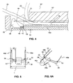
- FIG. 4 is cross-sectional view of a distal portion of an endoscope according to an embodiment of the present invention.
- FIG. 5 is a top view of components of an instrument positioning device according to an embodiment of the present invention.
- FIG. 6A is a perspective view of components of an instrument positioning device according to an embodiment of the present invention.
- FIG. 6B is a top view of components of an alternative instrument positioning device according to an embodiment of the present invention.
- FIG. 7A is a perspective view of a distal part of an endoscope according to an embodiment of the present invention.
- FIG. 7B is a front view of a distal part of an endoscope according to an embodiment of the present invention.
- FIG. 7C is a side view of a distal part of an endoscope according to an embodiment of the present invention.
- FIG. 8A is a side view of components of an alternative instrument positioning device according to an embodiment of the present invention.
- FIGS. 8B-8D are top views of components of alternative instrument positioning devices according to embodiments of the present invention.
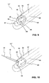
- FIG. 9 is a perspective view of a distal part of an endoscope.
- FIG. 10 is a perspective view of a distal part of an endoscope and a treatment instrument.
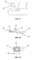
- FIG. 11 is a side view of a distal part of an endoscope.
- FIG. 12 is a side view of components of an alternative instrument positioning mechanism.
- FIG. 13 is a top view of components of an alternative instrument positioning mechanism.
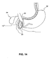
- FIG. 14 illustrates the positioning of an endoscope and treatment device within a patient's body portion.
- the invention relates to a medical device for positioning a treatment device and/or viewing a patient's internal body portion.
- the treatment device can be advanced through a working channel of an endoscope, including an endoscope specifically designed and/or sized for use with the treatment device, and into a tissue tract.
- treatment device or “treatment instrument” includes, for example, any working medical device advanced through a working channel of an endoscope and for use during an endoscopic procedure.
- Exemplary treatment instruments include, but are not limited to, guide wires, cutting or grasping forceps, biopsy devices, snare loops, injection needles, cutting blades, scissors, retractable baskets, retrieval devices, ablation and/or electrophysiology catheters, stent placement devices, surgical stapling devices, and balloon catheters.
- FIG. 1 illustrates a known endoscope system.
- distal refers to the end further from the device operator during use and "proximal” refers to the end closer to the device operator during use.
- FIG. 1 depicts an endoscope 10 including a flexible outer tube 12 extending between a distal end 14 and a proximal end 16 of the device.
- Endoscope 10 includes a treatment device insertion port 11 for receiving a treatment device 20 into a working channel of the endoscope 10.
- the distal end 14 of the endoscope system 10 includes a side facing operation window 18 that can include visualization and lighting components for viewing during a treatment procedure.
- a working channel (not shown) extends within the endoscope 10 and terminates at the operation window 18, thereby allowing the treatment instrument 20 to be extended from the distal end of the endoscope 10.
- the extension of the treatment instrument 20 at a desired treatment site can be then be viewed through the visualization components, which transmit images to the proximal end of the endoscope 10, as in known in the art. While FIG. 1 illustrates a side facing operation window 18, both front/forward facing and oblique/intermediate angled windows are known.
- FIG. 2 illustrates a cross-sectional view of a distal portion of a known endoscope system including a deflecting lever/elevator device for deflecting a treatment instrument as the instrument is extended beyond a working channel of an endoscope.
- a deflecting lever 22 is rotated clockwise about a pin 24 by means of a pull wire 26 connected to an upper portion of the deflecting lever 22.
- the deflecting lever 22 deflects the treatment device 20 in order to alter the angle at which the treatment device 20 exits the endoscope's working channel, resulting in the position of device 20 shown by the dashed lines in FIG. 2 .
- pull wire 26 the endoscope operator can control the placement of the treatment instrument 20 as it is positioned during a medical procedure.
- a handle 28 at the proximal end 16 of the device can include various positioning controls 30 to effectuate bending and rotation of the flexible outer tube 12 for positioning of the device during a medical procedure.
- the handle can include a distinct positioning control for actuation of the deflection lever pull wire 26.
- the deflection lever 26 is displaceable about a single axis (i.e. the axis coincident with the pin 24). Accordingly, lever 26 is movable about and only effectuates movement of the treatment device 20 through one degree of freedom. Precise manipulation of a treatment instrument is increased when manipulation is afforded along or about an additional particular coordinate axis. A degree of freedom describes flexibility of motion added due to displacement along or about a particular coordinate axis.
- FIG. 3 illustrates a known Cartesian coordinate system illustrating the three orthogonal axes of X, Y, and Z.
- a linkage or any system of connected bodies that has complete freedom of motion (even if only in a limited area) has six degrees of freedom.
- Three modes are translation (i.e. the ability to move in each of three dimensions in a direction parallel to each of the three orthogonal axes).
- An additional three modes are rotation, i.e. the ability to change an angular position around the three orthogonal axes. Only three degrees of freedom are necessary to move a structure anywhere in space, but additional degrees of freedom provide more versatility.
- each of the following is one degree of freedom: moving up and down along the Y axis (heaving); moving left and right along the X axis (swaying); moving forward and back along the Z axis (surging); tilting up and down (rotation Rx about the X axis); turning left and right (rotation Ry about the Y axis); and tilting side to side (rotation Rz about the Z axis).
- a positioning mechanism that effectuates movement through more than one degree of freedom will allow for more precise positioning of an underlying treatment device.
- FIG. 4 illustrates a cross-sectional view of a distal portion of an endoscope according to an embodiment of the present invention.
- FIG. 4 depicts a cross-sectional view of a distal end 14 of an improved endoscope 10'.
- the distal portion of endoscope 10' includes an exterior flexible outer tube 12', a side facing operation window aperture 32, and a working channel 34 forming a lumen within the endoscope 10' and extending from the proximal end of the endoscope 10' and terminating at the operation window aperture 32.
- a deflection elevator in the form of a positioning block 35 is housed within a recess 36 at the distal end of the endoscope 10' at a position opposite the operation window aperture 32.
- FIGS. 5-6B illustrate top and perspective views, respectively, of exemplary displacement mechanisms which control movement of the positioning block 35.
- positioning block 35 includes a curved concave surface 38 configured to maintain contact with a treatment instrument extended beyond the endoscope's working channel (see FIG. 4 ).
- the curved surface 38 of the positioning block 35 acts as the surface for transferring a deflection force against a treatment instrument 20 during extension of the treatment instrument 20.
- the positioning block 35 may include a closed top surface thereby forming an internal lumen for receiving a treatment instrument therein.
- the positioning block can be provided with a notch or channel formed in the concave surface 38.
- the notch can be provided with a "v" shaped trough sized to releasable engage a treatment instrument therein in a passive friction fit engagement.
- the positioning block 35 is disposed for operative connection within the distal end of the endoscope through a pin 40, which extends laterally within the endoscope's distal end 14 and perpendicular to the longitudinal axis of outer tube 12'.
- the pin 40 extends laterally within a pin aperture 42 formed in the body of positioning block 35.
- the pin 40 is fixed to the flexible tube 12' such that the positioning block 35 is configured to rotate about and translate laterally relative to the pin 40.
- Pin 40 extends through the aperture 42 but is not fixedly attached to positioning block 35. Accordingly, the positioning block 35 is configured to deflect a treatment instrument, such as, for example, device 20 extending within working channel 34.
- Positioning block 35 is configured for clockwise rotation about rotation pin 40 through actuation of a pull wire 44, illustrated in dashed lines in FIG. 4 .
- Pull wire 44 is connected at an upward offset distal position along the positioning block 35 such that proximal movement of pull wire 44 rotates the positioning block 35 about rotation pin 40.
- the pull wire 44 extends proximally within a pull wire channel (not shown) of the endoscope where it extends for connection with a positioning control device at a handle at the endoscope's proximal end.
- the positioning block 35 As pull wire 44 is displaced in a proximal direction, the positioning block 35, and in turn, the treatment instrument 20 (as seen in dashed lines in FIG. 4 ) are rotated such that the angle at which treatment instrument 20 extends from the endoscope 10' is increased.
- Pull wire 44 can extend for connection to a bending lever or rotation wheel control device where proximal actuation can be effected by an operator. While a pull wire element is illustrated as the mechanism for deflection of the positioning block 35, alternative deflection mechanisms can be used, including, but not limited to, forward acting push wires, or stylets, electronic piezoelectric bending transducers, and an inflatable cuff element underlying the positioning block 35.
- endoscope 10' is equipped with a lateral displacement mechanism.
- the pin 40 extends a lateral distance L within the recess 36 across the distal end of endoscope 10'.
- the pin 40 extends through the pin aperture 42 within the positioning block 35.
- positioning block 35 is also configured for lateral displacement relative to the pin 40 along the distance L between left and right sides of recess 36 within the distal end of endoscope 10'.
- Positioning block 35 includes surfaces 46a and 46b along opposite lateral sides of the block 35.
- Lateral displacement pull wires 48a and 48b are each connected at a point along the lateral side surfaces 46a and 46b of the positioning block 35.
- Pull wires 48a and 48b extend laterally away from the positioning block 35 where they wrap around and extend proximally away from force transmission posts 50, which extend upwardly within the endoscope recess 36.
- proximal actuation of pull wire 48a results in rightward lateral displacement of the positioning block 35 along the guide of pin 40.
- proximal actuation of pull wire 48b results in leftward lateral displacement of the positioning block 35 along the guide of pin 40.
- left and right force transmission posts 50 permit the transfer of a proximally directed force along either of pull wire 48a and 48b into a laterally transmitted force for displacement of the positioning block along the lateral distance L.
- Pull wires 48a and 48b therefore will exhibit some degree of flexibility in order to bend about posts 50 and allow for slack during rotation of positioning block 35.
- connection of lateral pull wires 48a and 48b should be selected in order to result in the least amount of interference with the rotation deflection of the positioning block 35 about rotation pin 40 through actuation of the deflection control wire 44.
- connection of lateral pull wires 48a, 48b and positioning block 35 may occur at a point just proximal of the aperture 42.
- the illustrated connection point is intended to be nonlimiting and alternative connection locations are permitted with a focus on reducing any interference with the free actuation of deflection wire 44.
- the pull wire arrangement illustrated for lateral displacement is also intended to be nonlimiting and alternative mechanisms for achieving lateral displacement of positioning block 35 are possible. Any alternative mechanical force transfer mechanism which transfers a back and forth force into a laterally directed force, such as, for example, a rack and pinion gear mechanism, can be utilized.
- FIG. 6B depicts a top view of an alternative positioning block 35'.
- the arrangement for the positioning block 35' only requires a single pull wire 49 instead of the two lateral pull wires 48a and 48b required by the arrangement of FIG. 6A .
- the single pull wire 49 connects to one side of the positioning block 35' and a spring 51 connects to another side of positioning block 35', opposite the surface of connection for pull wire 49.
- the end of spring 51 that is not attached to the positioning block 35' can be secured to an internal surface of the underlying endoscope within the recess 36.
- the arrangement of FIG. 6B differs from that of FIG. 6A , in that it includes only a single force transmission post 50 for interaction with pull wire 49.
- the positioning block 35' can then be manipulated and laterally displaced upon proximal actuation of the pull wire 49.
- the spring 51 acts on the positioning block 35' to return it to an initial resting position.
- FIGS. 7A-7C illustrate perspective, front, and side views, respectively, of a distal part of an endoscope 10" utilizing a combined lateral displacement and deflection controlled positioning block, according to an embodiment of the present invention.
- FIG. 7A illustrates a perspective view of a distal portion of the endoscope 10" including the operation window 32 including positioning block 35 for manipulation of a treatment instrument as well as a visualization device 52 and a lighting device 54 for viewing an internal body portion.
- FIG. 7B lateral displacement of positioning block 35 between left and right ends of the length L is illustrated.
- actuation of lateral pull wires 48a and 48b allow more precise manipulation of an extended treatment instrument 20 without trauma-causing movement of the underlying endoscope 10".
- the combined lateral movement and rotation of positioning block 35 allows for precise manipulation of a treatment instrument through two degrees of freedom as opposed to the single positioning degree of freedom afforded by past elevator rotation systems.
- FIG. 7C depicts a side view of the distal portion of endoscope 10" and in particular, the deflection of a treatment instrument 20 as it extends from a working channel of the endoscope 10".
- Actuation of deflection pull wire 44 causes rotation of positioning block 35 in order to increase or decrease the deflection angle ⁇ (as shown in FIG. 7C ) at which the treatment instrument extends from the working channel of underlying endoscope 10".
- rotation of positioning block 35 about pin 40 can cause deflection of treatment instrument 20 between an angle of about 30 degrees to about 135 degrees relative to the longitudinal axis of the endoscope 10".
- FIG. 8A is a side view of components of an alternative instrument positioning device according to an embodiment of the present invention.
- FIG. 8A depicts an alternative positioning block 35" similar to the positioning block 35 as previously described, with the feature of an elongated pin slot (or channel) 45 replacing the pin aperture 42 described above.
- the inclusion of the elongated pin slot 45 allows for a predetermined amount of controlled longitudinal (both in a distal and a proximal direction) displacement of the positioning block 35" relative to the underlying endoscope.
- the length of elongated pin slot 45 dictates the extent of longitudinal displacement for positioning block 35". At the distal-most and proximal-most displacement positions for positioning block 35", further movement of the positioning block 35" is prevented due to the engagement between an internal surface of the pin slot 45 and the rotation pin 40, housed therein. Back and forth movement of the positioning block 35" within a recess 36 of an underlying endoscope can be caused by any force actuation mechanism capable of displacing the positioning block 35". Examples include, but are not limited to, pull wires, pushable stylets, fluid pressure actuated force transmission mechanisms, and expandable balloons.
- the slot 45 may be filled with a compliant, self-healing material, such as a sponge material, for example. The inclusion of a sponge material within the slot 45 allows for stabilization of the pin 40 therein such that the pin returns to a centered rest position once a displacement force is no longer transmitted to the positioning block 35".
- Rotation of the positioning block 35" relative to the pin 40 can be achieved by maintaining the longitudinal position of the positioning block 35" within the recess 36 and then causing controlled rotation of the positioning block 35" in the manner described above. Maintaining the longitudinal position of the positioning block 35" can be achieved through any type of known active of passive position locking mechanism.
- FIGS. 8B and 8C illustrate partial cross-sectional views of the positioning block 35" depicting the position of pin 40 within the slot 45.
- the area of the slot 45 allows for the capability of partial angular displacement of the positioning block 35" within the housing recess. Accordingly, in addition to the pure lateral and longitudinal displacement capability for the displacement block 35", the area of slot 45 allows for partial angular displacement (as seen in FIG. 8C ) that allows for greater range of movement for the positioning block 35".
- FIG. 8D illustrates a partial cross-sectional view of the positioning block 35" depicting an alternative flexible rotation pin 40' disposed within the slot 45.
- the use of the flexible rotation pin 40' allows for further controlled angular displacement of the positioning block 35".
- the flexible characteristics of pin 40' allow for further angular displacement of the positioning block 35" beyond what is capable in an arrangement where the rotation pin is rigid. Control of the angular displacement of the positioning block 35" can be effectuated though the use of any known force transmission mechanism.
- FIG. 9 is a perspective view of a distal part of an endoscope according to another example.
- FIG. 9 depicts a distal portion of an endoscope 10"' including an operation window 56 in part forming an aperture 62 that houses a roller 60.
- the size of roller 60 can be selected to be retained within an operating window aperture 62.
- Roller 60 includes a lumen 64 therethrough that forms an extension of a working channel (not shown) of endoscope 10"', such that a treatment instrument can be extended through the distal opening of lumen 64 during a medical procedure.
- the roller 60 can be provided in any shape so long as it is rotatably housed within the aperture 62.
- Roller 60 may be housed within aperture 62 such that a ball and socket type connection joint is formed.
- roller 60 can be formed of a spherical shape as illustrated in FIGS. 9 and 10 .
- roller 60 can be formed to exhibit a cylindrical shape, an oblong, curved football shape, for example, or any three dimensional structure exhibiting a partially curved exterior surface configured for moving the opening of lumen 64 relative to the endoscope 10"' while housed within aperture 62. Accordingly, the relative shapes of roller 60 and aperture 62 should be coordinated in order to facilitate the housing and movement of roller 60 therein.
- roller 60 is configured for rotation within aperture 62 such that the opening of lumen 64 can be directed for more precise manipulation of a treatment instrument extending therethrough.
- Lumen 64 extending through the roller 60 is configured for receiving a treatment instrument as the treatment instrument extends distally through an interior working channel of endoscope 10"'. Since lumen 64 is configured to movably direct and adjust the direction at which the treatment instrument extends out of the endoscope 10"', the proximal end of lumen 64 must maintain communication with the distal opening of an interior working channel of endoscope 10"' that houses the treatment instrument. In one arrangement, for example, lumen 64 exhibits a cone shape 65, illustrated in FIG. 9 .
- lumen 64 extends distally from a large diameter opening at the proximal end to a relatively narrow diameter at the distal point of exit of lumen 64. Since the proximal end of lumen 64 exhibits a greater diameter opening, alignment and communication is maintained between an interior working channel of endoscope 10"' and lumen 64 as roller 60 is moved relative to the aperture 62.
- Roller 60 can be manipulated relative to the housing aperture 62 through a system of pull wires.
- FIG. 9 illustrates a system of four pull wires 66-69 for manipulation of roller 60.
- Pull wires 66-69 can be fixedly attached to the roller 60, each at a predetermined distance from the distal exit point of lumen 64.
- Pull wires 66-69 can each be spaced relative to the distal exit point of lumen 64, such that selective manipulation of each of the pull wires 66-69 allows for a predetermined degree of rotation of roller 60 about at least two orthogonal axes.
- proximal actuation of wire 68 coupled with a release of tension in wire 66 permits a controlled rotation of roller 60 relative to an axis extending upward in FIG.
- Tension within some of wires 66-69 may need to be selectively loosened in cooperation with selective tightening of others in the unit in order to permit controlled rotation of roller 60.
- the point of connection of each pull wire to roller 60 occurs at a constant predetermined distance from the distal point of exit of lumen 64 through roller 60.
- Pull wires 66-69 can be connected for operator manipulation through any type of known wire actuation device at the endoscope handle at the proximal end of the system. As is apparent from FIG. 9 , selective manipulation of each of the pull wires 66-69 allows for a predetermined degree of rotation of sphere 60 about three axes, like an eyeball. For example, with reference to FIGS. 3 and 9 , controlled manipulation of pull wires 66-69 allows for three degrees of freedom. While a system of four pull wires is disclosed as the manipulation mechanism for roller 60, any alternative mechanism for controlled displacement of the roller can be used. For example, alternative mechanisms for rotation of roller 60 (some of which are more particularly described below, with reference to FIGS. 11-13 ) include specifically positioned and controllable track rollers, an arrangement of three pull wires, or controlled actuation of selectively placed piezoelectric transducers.
- FIG. 10 depicts an arrangement of a distal portion of an endoscope similar to that of FIG. 9 and further including an additional positioning mechanism for manipulation of a treatment instrument 20.
- a treatment instrument 20 is extended through an opening of a lumen 64 that extends through roller 60.
- a slidable sleeve 70 configured for movement relative to the lumen 64 within which it is housed.
- Sleeve 70 can be configured to exhibit a predetermined level of rigidity such that a treatment instrument 20 extended therethrough will be reliably directed coincident with the direction sleeve 70 extends from lumen 64.
- sleeve 70 can be used to position the point in space at which the distal end of a treatment instrument 20 is located within a patient's body.
- This further positioning adjustment mechanism is advantageous in that the distal end of a treatment instrument can be precisely located without requiring repeated manipulation and trauma-casing movement of the entire underlying endoscope body. If the extended sleeve 70 is easily deflected and collapsible during contact with internal body tissues, proper control and repeatable placement of sleeve 70 (and in turn, the treatment instrument 20 extended therethrough) may not be possible. Accordingly, construction of sleeve 70 with a predetermined level of rigidity is advantageous.
- Sleeve 70 may be configured for back and forth movement within lumen 64 through a pushable actuation wire (not shown) proximally extending through endoscope 10"'.
- the actuation wire could be configured for connection to the proximal end of sleeve 70 such that back and forth movement of the actuation wire through endoscope 10"' is translated into back and forth movement of sleeve 70.
- slidable sleeve 70 within lumen 64 also affords an added two degrees of freedom to the endoscope system.
- sleeve 70 can be manipulated by an operator to move forward and backward within lumen 64.
- sleeve 70 can be sized to receive and engage the exterior surface of the treatment instrument 20 through a friction fit, such that controlled rotation of sleeve 70 within lumen 64 effectuates rotation of a treatment instrument 20 extending therein.
- sleeve 70 can be configured to engage the treatment instrument 20 in a friction fit such that back and forth movement of sleeve 70 effectuates back and forth displacement of instrument 20.
- the controlled rotation of treatment instrument 20 by rotation of sleeve 70 can be effectuated through a complimentary groove and recess arrangement between the interior surface of sleeve 70 and the exterior surface of the treatment instrument 20. Accordingly, a treatment instrument 20 can be precisely manipulated through controlled rotation of roller 60, through forward and backward movement of sleeve 70, and through rotation of sleeve 70, to impart rotation to treatment instrument 20.
- FIG. 11 depicts a side view of a distal part of an endoscope according to another example.
- a generic endoscope 10 is depicted housing a positioning sleeve 71 therein.
- the positioning sleeve 71 includes a roller 60 positioned at the distal end thereof.
- the positioning sleeve 71 can itself be manipulated and positioned relative to the underlying endoscope 10.
- the roller 60 at the distal end of the positioning sleeve 71 can also be precisely rotated and positioned relative to the sleeve 71.
- the roller 60 includes a lumen 64 for receiving a treatment instrument therein.
- the angular position of a treatment instrument can then be precisely controlled through controlled rotation and positioning of the roller 60 relative to the sleeve 71.
- controlled rotation can be effectuated through a system of pull wires, as described above, or through any other force transmission mechanism capable of moving roller 60.
- FIG. 12 depicts a side view of components of an alternative instrument positioning mechanism for the roller 60 described in FIGS. 9-11 .
- rotation of roller 60 can be effectuated through proximal movement of a wedge 90 connected to a pull wire 92.
- the wedge 90 includes an inclined surface 91. Interaction between the inclined surface 91 of the wedge 90 and the exterior surface of the roller 60 leads in turn to controlled rotation of the roller 60 upon proximal actuation of the pull wire 92.
- proximal movement of the wedge 90 and the pull wire 92 in the direction of arrow 93 results in rotation of roller 60 in the direction of arrow 94.
- the particular materials for the exterior surface of roller 60 and the inclined surface 91 can be selected to decrease the amount of sliding therebetween.
- FIG. 13 depicts a top view of components of an alternative instrument positioning mechanism for the roller 60 described in FIGS. 9-11 .
- FIG. 13 depicts a movable base component 94, upon which roller 60 rests. Due to the interaction between roller 60 and the surface of base component 94, controlled lateral and longitudinal displacement of the base component 94 within an endoscope recess 36 results in controlled rotation of roller 60. Movement of the base component 94 can be effectuated in both longitudinal directions designated by arrow 95 as well as lateral directions designated by arrow 96.
- the particular positioning mechanism for a treatment instrument can be equipped with any type of known locking mechanism for the purpose of releasably maintaining a particular position of a treatment instrument relative to an endoscope.
- FIG. 14 illustrates the positioning of an endoscope 10', 10", or 10"' and treatment device 20 within a patient's body portion.
- FIG. 14 depicts the extension of a treatment instrument 20 within a particular bile duct 80 during an ERCP procedure.
- the endoscope 10"' for example, is inserted and extended through a patient's stomach 82 such that the distal end and aperture 62 (not shown) of endoscope 10"' are positioned is close relation to a particular bile duct 80 leading to, for example, gall bladder 84.
- treatment instrument 20 is extended beyond the internal working channel of endoscope 10"'.
- the treatment instrument can then be precisely manipulated, for example, by controlled rotation of roller 60 and/or the additional extension of sleeve 70 beyond endoscope 10"', described above.
- further manipulation of instrument 20 can be effectuated through rotation of sleeve 70, for example.
- Precise manipulation of treatment instrument 20 allows for more precise positioning and location of instrument 20 such as, for example, during placement of instrument 20 within a particular bile duct 80 of interest. More precise manipulation of a treatment device 20 can result in shortened treatment procedures by reducing the amount of time necessary to effectuate proper position of the treatment device 20.
- controlled deflection of the angle at which treatment device 20 exits the underlying endoscope 10"' can reduce internal tissue trauma caused during endoscopic procedures requiring repeated repositioning and manipulation of the entire endoscope during location of the endoscope.
- the positioning mechanisms described above facilitate the location of treatment instrument 20 within a particular bile duct 80 such that the duration of, and occurrence of tissue trauma during, a treatment procedure can be reduced.
Landscapes
- Health & Medical Sciences (AREA)
- Life Sciences & Earth Sciences (AREA)
- Surgery (AREA)
- Biomedical Technology (AREA)
- Medical Informatics (AREA)
- Optics & Photonics (AREA)
- Pathology (AREA)
- Radiology & Medical Imaging (AREA)
- Biophysics (AREA)
- Engineering & Computer Science (AREA)
- Physics & Mathematics (AREA)
- Heart & Thoracic Surgery (AREA)
- Nuclear Medicine, Radiotherapy & Molecular Imaging (AREA)
- Molecular Biology (AREA)
- Animal Behavior & Ethology (AREA)
- General Health & Medical Sciences (AREA)
- Public Health (AREA)
- Veterinary Medicine (AREA)
- Endoscopes (AREA)
- Surgical Instruments (AREA)
- Infusion, Injection, And Reservoir Apparatuses (AREA)
Claims (15)
- Dispositif médical, comprenant :• un tube flexible allongé (12') comportant une extrémité distale et extrémité proximale et définissant une lumière qui s'étend depuis l'extrémité proximale jusqu'à un orifice à l'extrémité distale ; et• un mécanisme de positionnement (35, 35', 35") positionné à l'extrémité distale du tube flexible (12') à proximité de l'orifice, le mécanisme de positionnement étant configuré pour se déplacer selon au moins deux degrés de liberté pour transmettre une force à un instrument de traitement qui s'étend à travers la lumière et pour contrôler une direction dans laquelle un instrument de traitement s'étend à partir de l'orifice,caractérisé en ce que le mécanisme de positionnement est logé dans un logement (36) à l'extrémité distale du tube flexible (12'), le mécanisme de positionnement étant configuré pour tourner autour d'un axe (40) dans le logement (36), et en ce que le mécanisme de positionnement est configuré pour un déplacement latéral dans le logement (36) et le long de l'axe (40).
- Dispositif médical selon la revendication 1, dans lequel le mécanisme de positionnement est configuré pour un déplacement longitudinal dans le logement (36).
- Dispositif médical selon la revendication 2, dans lequel le mécanisme de positionnement comprend une rainure allongée (45) qui le traverse et reçoit l'axe (40) de telle sorte que le mécanisme de positionnement est configuré pour un déplacement longitudinal par rapport à l'axe (40).
- Dispositif médical selon la revendication 3, dans lequel un matériau spongieux élastique est inclus dans une partie de la rainure allongée (45) de telle sorte que le mécanisme de positionnement retourne dans une position longitudinale de repos lorsque des forces d'actionnement dirigées longitudinalement ne sont plus appliquées au mécanisme de positionnement.
- Dispositif médical selon la revendication 2, dans lequel le mécanisme de positionnement est configuré pour un déplacement angulaire grâce au déplacements latéral et longitudinal combinés du mécanisme de positionnement.
- Dispositif médical selon la revendication 5, dans lequel l'axe (40) comprend un matériau élastique et flexible de telle sorte que le mécanisme de positionnement est configuré pour un déplacement angulaire additionnel grâce au déplacements latéral et longitudinal combinés du mécanisme de positionnement.
- Dispositif médical selon la revendication 2, dans lequel le mécanisme de positionnement est configuré pour un déplacement latéral dans une première direction par l'actionnement d'un fil de traction (48a, 48b) connecté à un premier côté du mécanisme de positionnement.
- Dispositif médical selon la revendication 7, comprenant en outre un ressort connecté à une extrémité d'un deuxième côté du mécanisme de positionnement, opposé au premier côté du mécanisme de positionnement, et connecté à une autre extrémité du tube flexible (12') de telle sorte qu'après l'actionnement du fil de traction (48a, 48b), le mécanisme de positionnement retourne en position de repos.
- Dispositif médical selon la revendication 7, dans lequel le mécanisme de positionnement est configuré pour un déplacement latéral dans une deuxième direction, opposées à la première direction, par l'actionnement d'un fil de traction (48a, 48b) connecté à un deuxième côté du mécanisme de positionnement opposé au premier côté du mécanisme de positionnement.
- Dispositif médical selon la revendication 9, dans lequel les fils de traction (48a, 48b) connectés aux premier et deuxième côtés du mécanisme de positionnement s'étendent latéralement à partir du mécanisme de positionnement, s'enroulent autour de piliers situés dans le logement (36) et s'étendent à proximité de ceux-ci.
- Dispositif médical selon la revendication 9, dans lequel le mécanisme de positionnement comprend une surface concave (38) configurée pour maintenir un contact avec un instrument de traitement qui s'étend de façon distale au-delà de la lumière.
- Dispositif médical selon la revendication 1, dans lequel l'orifice est un orifice faisant face au côté et qui s'ouvre latéralement le long du tube flexible (12') .
- Dispositif médical selon la revendication, 1, dans lequel le mécanisme de positionnement est configuré pour se déplacer selon au moins trois degrés de liberté.
- Dispositif médical selon la revendication 13, dans lequel le mécanisme de positionnement peut tourner autour de trois axes orthogonaux.
- Dispositif médical selon la revendication 1, dans lequel le dispositif médical est un endoscope (10') qui comporte des composants de visualisation et/ou d'illumination, et/ou qui comporte un mécanisme de positionnement additionnel pour obtenir une déflexion contrôlée du tube flexible allongé (12').
Applications Claiming Priority (2)
| Application Number | Priority Date | Filing Date | Title |
|---|---|---|---|
| US83259406P | 2006-07-24 | 2006-07-24 | |
| PCT/US2007/073769 WO2008014162A1 (fr) | 2006-07-24 | 2007-07-18 | Système de positionnement pour manipuler un instrument de traitement à l'extrémité d'un dispositif médical |
Publications (2)
| Publication Number | Publication Date |
|---|---|
| EP2049005A1 EP2049005A1 (fr) | 2009-04-22 |
| EP2049005B1 true EP2049005B1 (fr) | 2013-03-13 |
Family
ID=38662961
Family Applications (1)
| Application Number | Title | Priority Date | Filing Date |
|---|---|---|---|
| EP07799676A Active EP2049005B1 (fr) | 2006-07-24 | 2007-07-18 | Système de positionnement pour manipuler un instrument de traitement à l'extrémité d'un dispositif médical |
Country Status (5)
| Country | Link |
|---|---|
| US (1) | US9427139B2 (fr) |
| EP (1) | EP2049005B1 (fr) |
| JP (1) | JP5286263B2 (fr) |
| CA (1) | CA2657841A1 (fr) |
| WO (1) | WO2008014162A1 (fr) |
Families Citing this family (35)
| Publication number | Priority date | Publication date | Assignee | Title |
|---|---|---|---|---|
| US8872906B2 (en) * | 2005-01-05 | 2014-10-28 | Avantis Medical Systems, Inc. | Endoscope assembly with a polarizing filter |
| US20060149129A1 (en) * | 2005-01-05 | 2006-07-06 | Watts H D | Catheter with multiple visual elements |
| US8797392B2 (en) * | 2005-01-05 | 2014-08-05 | Avantis Medical Sytems, Inc. | Endoscope assembly with a polarizing filter |
| US8289381B2 (en) * | 2005-01-05 | 2012-10-16 | Avantis Medical Systems, Inc. | Endoscope with an imaging catheter assembly and method of configuring an endoscope |
| WO2007087421A2 (fr) * | 2006-01-23 | 2007-08-02 | Avantis Medical Systems, Inc. | Endoscope |
| US8287446B2 (en) * | 2006-04-18 | 2012-10-16 | Avantis Medical Systems, Inc. | Vibratory device, endoscope having such a device, method for configuring an endoscope, and method of reducing looping of an endoscope |
| EP2023794A2 (fr) * | 2006-05-19 | 2009-02-18 | Avantis Medical Systems, Inc. | Système et procédé permettant de produire et d'améliorer des images |
| US20090231419A1 (en) * | 2007-02-06 | 2009-09-17 | Avantis Medical Systems, Inc. | Endoscope Assembly and Method of Performing a Medical Procedure |
| US20080214890A1 (en) * | 2007-03-01 | 2008-09-04 | Olympus Medical Systems Corporation | Therapeutic method and therapeutic system used with steps for approaching to lesion using overtube |
| US8064666B2 (en) | 2007-04-10 | 2011-11-22 | Avantis Medical Systems, Inc. | Method and device for examining or imaging an interior surface of a cavity |
| WO2009049324A1 (fr) * | 2007-10-11 | 2009-04-16 | Avantis Medical Systems, Inc. | Procédé et dispositif de réduction de bruit à cycle fixe d'image numérique |
| EP2330965B1 (fr) * | 2008-09-05 | 2018-07-11 | Carnegie Mellon University | Dispositif endoscopique à liaisons multiples avec assemblage distal sphérique |
| JP5427743B2 (ja) * | 2010-09-27 | 2014-02-26 | 富士フイルム株式会社 | 内視鏡装置 |
| JP2012075658A (ja) * | 2010-09-30 | 2012-04-19 | Fujifilm Corp | 内視鏡装置 |
| CN106214110B (zh) | 2011-02-16 | 2018-03-20 | 通用医疗公司 | 用于内窥镜的光耦合器 |
| DE102011005255A1 (de) * | 2011-03-08 | 2012-09-13 | Olympus Winter & Ibe Gmbh | Vorrichtung zur Umschaltung einer Blickrichtung eines Videoendoskops |
| WO2012158971A2 (fr) * | 2011-05-17 | 2012-11-22 | Ammirati Mario | Méthode et appareil de pose d'un endoscope au moyen d'instruments micro-chirurgicaux au cours d'une opération chirurgicale microscopique |
| WO2013051168A1 (fr) * | 2011-10-03 | 2013-04-11 | Serendipity株式会社 | Dispositif de capture d'image et endoscope rigide |
| US11234581B2 (en) * | 2014-05-02 | 2022-02-01 | Endochoice, Inc. | Elevator for directing medical tool |
| WO2015196380A1 (fr) | 2014-06-25 | 2015-12-30 | Liu Chia-Yua | Système auxiliaire d'endoscope ultra-mince et procédé d'utilisation |
| EP3158912A4 (fr) * | 2014-07-28 | 2018-02-14 | Olympus Corporation | Endoscope |
| US9459442B2 (en) | 2014-09-23 | 2016-10-04 | Scott Miller | Optical coupler for optical imaging visualization device |
| US10143363B2 (en) * | 2015-04-30 | 2018-12-04 | Ki Bong Kim | Endoscopic instrument |
| US10682120B2 (en) | 2015-04-30 | 2020-06-16 | Kmedisys | Endoscopic instrument |
| US10548467B2 (en) | 2015-06-02 | 2020-02-04 | GI Scientific, LLC | Conductive optical element |
| CA2992739A1 (fr) | 2015-07-21 | 2017-01-26 | GI Scientific, LLC | Accessoire d'endoscope avec portail de sortie a reglage angulaire |
| DE102015113020B4 (de) * | 2015-08-07 | 2023-10-05 | Digital Endoscopy Gmbh | Endoskopkopf |
| EP3403566A4 (fr) * | 2016-01-14 | 2019-09-18 | Olympus Corporation | Gaine d'endoscope, endoscope, unité de couverture, et unité d'endoscope |
| WO2018058007A1 (fr) * | 2016-09-23 | 2018-03-29 | Safeview Medical, Llc | Dispositifs et procédés pour imagerie interne |
| US10758271B2 (en) | 2016-10-14 | 2020-09-01 | Pacesetter, Inc. | Catheter-based system for delivery and retrieval of a leadless pacemaker |
| CN110234264B (zh) * | 2017-02-01 | 2022-11-15 | 波士顿科学国际有限公司 | 具有多个观察方向的内窥镜 |
| WO2018160811A1 (fr) | 2017-03-03 | 2018-09-07 | Boston Scientific Scimed, Inc. | Pointe de dispositif |
| KR101929318B1 (ko) | 2017-03-16 | 2018-12-18 | 주식회사 지에스엠티 | 워킹채널 내 도구 정렬기능을 갖는 카테터 |
| US20210113231A1 (en) * | 2018-06-13 | 2021-04-22 | Endoscopytools, Llc | Endoscopic tools with soft tip and method |
| US11723523B2 (en) | 2020-01-07 | 2023-08-15 | Gyrus Acmi, Inc. | One-piece elevator for a duodenoscope |
Family Cites Families (13)
| Publication number | Priority date | Publication date | Assignee | Title |
|---|---|---|---|---|
| JPS56156144A (en) * | 1980-04-30 | 1981-12-02 | Olympus Optical Co | Ultrasonic scanner apparatus for inspecting body cavity |
| US5460168A (en) * | 1992-12-25 | 1995-10-24 | Olympus Optical Co., Ltd. | Endoscope cover assembly and cover-system endoscope |
| JP3543027B2 (ja) * | 1995-04-10 | 2004-07-14 | オリンパス株式会社 | プローブ用湾曲シース |
| US6027460A (en) * | 1995-09-14 | 2000-02-22 | Shturman Cardiology Systems, Inc. | Rotatable intravascular apparatus |
| US5924976A (en) | 1997-08-21 | 1999-07-20 | Stelzer; Paul | Minimally invasive surgery device |
| JP4716594B2 (ja) * | 2000-04-17 | 2011-07-06 | オリンパス株式会社 | 内視鏡 |
| US6824509B2 (en) | 2001-07-23 | 2004-11-30 | Olympus Corporation | Endoscope |
| JP3938710B2 (ja) | 2002-04-26 | 2007-06-27 | オリンパス株式会社 | 内視鏡 |
| JP4488280B2 (ja) | 2002-06-07 | 2010-06-23 | オリンパス株式会社 | 内視鏡用処置具および内視鏡装置 |
| US20050006501A1 (en) * | 2003-06-11 | 2005-01-13 | Englefield Derek John | Fluid control in jets |
| JP4895509B2 (ja) * | 2005-02-09 | 2012-03-14 | Hoya株式会社 | 内視鏡用処置具 |
| EP1955643B1 (fr) * | 2005-12-01 | 2019-01-09 | Olympus Corporation | Long membre de guidage médical et long appareil médical |
| US7815564B2 (en) * | 2006-02-21 | 2010-10-19 | Boston Scientific Scimed, Inc. | Positioning system for manipulating a channel within a medical device |
-
2007
- 2007-07-18 WO PCT/US2007/073769 patent/WO2008014162A1/fr active Application Filing
- 2007-07-18 JP JP2009521903A patent/JP5286263B2/ja active Active
- 2007-07-18 EP EP07799676A patent/EP2049005B1/fr active Active
- 2007-07-18 US US11/779,532 patent/US9427139B2/en active Active
- 2007-07-18 CA CA002657841A patent/CA2657841A1/fr not_active Abandoned
Also Published As
| Publication number | Publication date |
|---|---|
| CA2657841A1 (fr) | 2008-01-31 |
| WO2008014162A1 (fr) | 2008-01-31 |
| JP5286263B2 (ja) | 2013-09-11 |
| US20080021269A1 (en) | 2008-01-24 |
| US9427139B2 (en) | 2016-08-30 |
| EP2049005A1 (fr) | 2009-04-22 |
| JP2009544421A (ja) | 2009-12-17 |
Similar Documents
| Publication | Publication Date | Title |
|---|---|---|
| EP2049005B1 (fr) | Système de positionnement pour manipuler un instrument de traitement à l'extrémité d'un dispositif médical | |
| US9179825B2 (en) | Positioning system for manipulating a channel within a medical device | |
| US11937774B2 (en) | Medical device positioning system | |
| EP2142071B1 (fr) | Enveloppe tubulaire orientable | |
| US20070265494A1 (en) | Flexible and retractable endoscope elevator | |
| US20090312645A1 (en) | Methods and Devices for Accessing Anatomic Structures | |
| US8435170B2 (en) | Positioning system for securing a treatment instrument at the end of a medical device | |
| US20210015348A1 (en) | Endoscopic tool stabilization and related methods of use | |
| US20230017488A1 (en) | Medical device with extendable shaft |
Legal Events
| Date | Code | Title | Description |
|---|---|---|---|
| PUAI | Public reference made under article 153(3) epc to a published international application that has entered the european phase |
Free format text: ORIGINAL CODE: 0009012 |
|
| 17P | Request for examination filed |
Effective date: 20090218 |
|
| AK | Designated contracting states |
Kind code of ref document: A1 Designated state(s): AT BE BG CH CY CZ DE DK EE ES FI FR GB GR HU IE IS IT LI LT LU LV MC MT NL PL PT RO SE SI SK TR |
|
| AX | Request for extension of the european patent |
Extension state: AL BA HR MK RS |
|
| RIN1 | Information on inventor provided before grant (corrected) |
Inventor name: RICHARDSON, KEVIN Inventor name: TINKHAM, BRIAN |
|
| RBV | Designated contracting states (corrected) |
Designated state(s): DE ES FR GB IE |
|
| 17Q | First examination report despatched |
Effective date: 20100907 |
|
| DAX | Request for extension of the european patent (deleted) | ||
| GRAP | Despatch of communication of intention to grant a patent |
Free format text: ORIGINAL CODE: EPIDOSNIGR1 |
|
| GRAS | Grant fee paid |
Free format text: ORIGINAL CODE: EPIDOSNIGR3 |
|
| GRAA | (expected) grant |
Free format text: ORIGINAL CODE: 0009210 |
|
| AK | Designated contracting states |
Kind code of ref document: B1 Designated state(s): DE ES FR GB IE |
|
| REG | Reference to a national code |
Ref country code: GB Ref legal event code: FG4D |
|
| REG | Reference to a national code |
Ref country code: IE Ref legal event code: FG4D |
|
| REG | Reference to a national code |
Ref country code: DE Ref legal event code: R096 Ref document number: 602007029079 Country of ref document: DE Effective date: 20130508 |
|
| PG25 | Lapsed in a contracting state [announced via postgrant information from national office to epo] |
Ref country code: ES Free format text: LAPSE BECAUSE OF FAILURE TO SUBMIT A TRANSLATION OF THE DESCRIPTION OR TO PAY THE FEE WITHIN THE PRESCRIBED TIME-LIMIT Effective date: 20130624 |
|
| PLBE | No opposition filed within time limit |
Free format text: ORIGINAL CODE: 0009261 |
|
| STAA | Information on the status of an ep patent application or granted ep patent |
Free format text: STATUS: NO OPPOSITION FILED WITHIN TIME LIMIT |
|
| 26N | No opposition filed |
Effective date: 20131216 |
|
| REG | Reference to a national code |
Ref country code: DE Ref legal event code: R097 Ref document number: 602007029079 Country of ref document: DE Effective date: 20131216 |
|
| REG | Reference to a national code |
Ref country code: FR Ref legal event code: CA Effective date: 20140513 |
|
| REG | Reference to a national code |
Ref country code: DE Ref legal event code: R082 Ref document number: 602007029079 Country of ref document: DE Representative=s name: VOSSIUS & PARTNER PATENTANWAELTE RECHTSANWAELT, DE |
|
| REG | Reference to a national code |
Ref country code: DE Ref legal event code: R082 Ref document number: 602007029079 Country of ref document: DE Representative=s name: VOSSIUS & PARTNER PATENTANWAELTE RECHTSANWAELT, DE |
|
| REG | Reference to a national code |
Ref country code: DE Ref legal event code: R082 Ref document number: 602007029079 Country of ref document: DE Representative=s name: VOSSIUS & PARTNER PATENTANWAELTE RECHTSANWAELT, DE Effective date: 20150202 Ref country code: DE Ref legal event code: R081 Ref document number: 602007029079 Country of ref document: DE Owner name: BOSTON SCIENTIFIC LIMITED, BM Free format text: FORMER OWNER: BOSTON SCIENTIFIC LTD., CHRIST CHURCH, BB Effective date: 20150202 Ref country code: DE Ref legal event code: R082 Ref document number: 602007029079 Country of ref document: DE Representative=s name: VOSSIUS & PARTNER PATENTANWAELTE RECHTSANWAELT, DE Effective date: 20141026 |
|
| REG | Reference to a national code |
Ref country code: FR Ref legal event code: PLFP Year of fee payment: 10 |
|
| REG | Reference to a national code |
Ref country code: FR Ref legal event code: PLFP Year of fee payment: 11 |
|
| PGFP | Annual fee paid to national office [announced via postgrant information from national office to epo] |
Ref country code: FR Payment date: 20170613 Year of fee payment: 11 |
|
| PG25 | Lapsed in a contracting state [announced via postgrant information from national office to epo] |
Ref country code: FR Free format text: LAPSE BECAUSE OF NON-PAYMENT OF DUE FEES Effective date: 20180731 |
|
| REG | Reference to a national code |
Ref country code: DE Ref legal event code: R081 Ref document number: 602007029079 Country of ref document: DE Owner name: BOSTON SCIENTIFIC MEDICAL DEVICE LIMITED, IE Free format text: FORMER OWNER: BOSTON SCIENTIFIC LIMITED, HAMILTON, BM |
|
| PGFP | Annual fee paid to national office [announced via postgrant information from national office to epo] |
Ref country code: IE Payment date: 20230622 Year of fee payment: 17 |
|
| PGFP | Annual fee paid to national office [announced via postgrant information from national office to epo] |
Ref country code: GB Payment date: 20230620 Year of fee payment: 17 |
|
| PGFP | Annual fee paid to national office [announced via postgrant information from national office to epo] |
Ref country code: DE Payment date: 20230620 Year of fee payment: 17 |
|
| REG | Reference to a national code |
Ref country code: GB Ref legal event code: 732E Free format text: REGISTERED BETWEEN 20231116 AND 20231122 |