EP2048066A2 - Motorcycle - Google Patents
Motorcycle Download PDFInfo
- Publication number
- EP2048066A2 EP2048066A2 EP08017827A EP08017827A EP2048066A2 EP 2048066 A2 EP2048066 A2 EP 2048066A2 EP 08017827 A EP08017827 A EP 08017827A EP 08017827 A EP08017827 A EP 08017827A EP 2048066 A2 EP2048066 A2 EP 2048066A2
- Authority
- EP
- European Patent Office
- Prior art keywords
- stand
- exhaust pipe
- engine
- stand body
- motorcycle
- Prior art date
- Legal status (The legal status is an assumption and is not a legal conclusion. Google has not performed a legal analysis and makes no representation as to the accuracy of the status listed.)
- Granted
Links
Images



Classifications
-
- B—PERFORMING OPERATIONS; TRANSPORTING
- B62—LAND VEHICLES FOR TRAVELLING OTHERWISE THAN ON RAILS
- B62H—CYCLE STANDS; SUPPORTS OR HOLDERS FOR PARKING OR STORING CYCLES; APPLIANCES PREVENTING OR INDICATING UNAUTHORIZED USE OR THEFT OF CYCLES; LOCKS INTEGRAL WITH CYCLES; DEVICES FOR LEARNING TO RIDE CYCLES
- B62H1/00—Supports or stands forming part of or attached to cycles
- B62H1/02—Articulated stands, e.g. in the shape of hinged arms
Definitions
- the present invention relates to a motorcycle comprising a side stand that uprises a vehicle body in a state of being inclined on one side in a vehicle width direction.
- motorcycles comprise a side stand that uprises a vehicle body in a state of being inclined on one side in a vehicle width direction.
- a motorcycle is provided with a side stand of this kind, an exhaust pipe connected to an engine is arranged along a bottom surface of the engine, a downtube is arranged along left and right side walls of the engine, and a stand body is mounted to the downtube through a bracket to be able to swing.
- a motorcycle comprising: a body frame, an engine mounted to the body frame, said engine having a side wall portion, an exhaust device connected to the engine, said exhaust device including an exhaust pipe, and a side stand configured to uprise the motorcycle in a state when being inclined in motorcycle width direction, wherein the side stand is mounted to the side wall portion of the engine between the exhaust pipe and the side wall portion.
- the side stand is mounted to the side wall portion to be positioned between the exhaust pipe and the side wall portion of the engine, so that it is possible to arrange the exhaust pipe toward a center of a vehicle as compared with the case where a side stand is mounted to a downtube arranged laterally of a side wall portion of an engine and an exhaust pipe is arranged outside the side stand. Consequently, a bank angle is easy to ensure, so that it is possible to achieve an improvement in freedom in a configuration position in a height direction of an exhaust pipe.
- the exhaust device is disposed laterally of the side wall portion of the engine and extends in moving direction of the motorcycle rearwardly.
- the side stand includes a stand body configured to ground a road surface and a stand bracket supporting the stand body to enable the same to turn between a service position and a storage position, and the stand bracket is mounted to the side wall portion of the engine.
- the stand bracket includes a mount flange portion mounted to the side wall portion of the engine, a support portion supporting the stand body, the stand body being turnably supported by a rotating shaft fixed to the support portion.
- the rotating shaft projects from the support portion on an opposite side with regard to the exhaust pipe, and/or the stand body is arranged to abut against a support surface of the support portion formed on an opposite side with regard to the exhaust pipe.
- the stand body includes a connection connected to the stand bracket, and, preferably, the rotating shaft includes a journal portion that journals the connection.
- the rotating shaft includes a load receiving portion that abuts against the support surface.
- the load receiving portion has a larger diameter than a diameter of the journal portion.
- the stand body and the exhaust pipe intersect each other as viewed in plan view.
- the exhaust device includes a recess disposed intermediately of an exhaust path to be dented inward in a motorcycle width direction.
- a tip end of the stand body overlaps the recess as viewed laterally.
- a tip end of the stand body is positioned in the recess as viewed in plan view.
- the exhaust device further includes a displacement chamber, to which the exhaust pipe is connected, and, preferably, the recess is formed at a connection of the displacement chamber and the exhaust pipe.
- a muffler is connected to the displacement chamber, and, preferably, the recess is formed at a connection of the displacement chamber to the exhaust pipe and the muffler.
- Figs. 1 to 8 are views illustrating a motorcycle according to an embodiment.
- front and rear, and left and right referred to in descriptions of the embodiment mean front and rear, and left and right as seen in a state of being seated on a seat unless otherwise specified.
- the reference numeral 1 denotes a motorcycle, the motorcycle 1 having the following outline construction.
- a head pipe 2a at a front end of a body frame 2 supports a front fork 3 to make the same steerable left and right.
- a front wheel 4 is journaled at a lower end of the front fork 3, and the front wheel 4 is covered by a front fender 5, the front fender 5 being mounted to a lower portion of the front fork 3.
- the front fork 3 has a headlight device 6 arranged on an upper portion thereof and has a steering handle 7 fixed at an upper end thereof.
- the body frame 2 has an engine unit 8 suspended by a front suspension bracket 9, a central suspension bracket 10, and a rear arm bracket portion 2b of the body frame 2.
- An intake device 12 and an exhaust device 13 are connected to the engine unit 8 and a radiator device 14 is arranged forwardly of the engine unit.
- a frame cover 15 covers the intake device 12 from above and an indicator device 16 representative of a vehicular state is arranged on the frame cover 15.
- a side stand 21 is arranged on a left wall lower portion of the engine unit 8 to have the motorcycle 1 uprising in a state of being a little inclined leftward.
- the rear arm bracket portion 2b of the body frame 2 supports a rear arm 17 to enable the same to swing vertically and a rear wheel 18 is supported at a rear end of the rear arm 17.
- the rear wheel 18 and the front wheel 4 are braked by a hydraulic brake device 22.
- a rear wheel suspension 19 is arranged between the rear arm 17 and the rear arm bracket portion 2b, the rear wheel suspension 19 comprising a remote type operating characteristics adjustment mechanism 25.
- a fuel tank 20 is arranged above the rear wheel suspension 19.
- a hydraulic control unit 22a of the brake device 22 is arranged forwardly of and obliquely upwardly of the fuel tank 20.
- a main seat 23a is arranged to cover upper portions of the hydraulic control unit 22a and the fuel tank 20, and a tandem seat 23b is arranged contiguous to the main seat 23a.
- the reference numeral 23c denotes a backrest that supports a rider's waist.
- a rear fender 24 that covers the rear wheel 18 from above is arranged below the tandem seat 23b.
- the engine unit 8 is of a water-cooled four-stroke V-type four-cylinder engine arranging left and right, front cylinders 8a and left and right, rear cylinders 8b on a crank case 8c to define a V bank in a longitudinal direction.
- An oil pan 8d is connected to a bottom surface of the crank case 8c.
- the exhaust device 13 includes a front exhaust pipe 13a connected to the front cylinder 8a of the engine unit 8, a rear exhaust pipe 13b connected to the rear cylinder 8b, an exhaust chamber (displacement chamber) 13bc, to which the respective exhaust pipes 13a, 13b are connected and which is common to all the cylinders, and left and right mufflers 13e, 13e connected to a side wall 13d of the exhaust chamber 13c to extend rearward and obliquely upward on both the left and right of the vehicle.
- the exhaust chamber 13c is in the form of a flat box including an upper wall 13f and a lower wall 13g, which are formed substantially flat, and a side wall 13d arranged to surround peripheries of the both walls, the exhaust chamber being arranged below a front portion of the rear arm 17 and between the rear wheel 18 and a bottom of the engine unit 8.
- the rear exhaust pipe 13b extends rearward from the rear cylinder 8b and bends downward to be connected to a front portion of the upper wall 13f of the exhaust chamber 13c.
- the front exhaust pipe 13a extends rearward and obliquely downward while diverging a little outward from the front cylinder 8a and bends rearward to extend rearward along a side wall portion 8c' of the crank case 8c.
- a rear end 13a' of the front exhaust pipe 13a is connected to a front portion of the side wall 13d of the exhaust chamber 13c while bending arcuately inward in a vehicle width direction.
- the left and right mufflers 13e, 13e are connected to the side wall 13d of the exhaust chamber 13c and its connection 13e' projects in the vehicle width direction. Consequently, a recess A dented inward in the vehicle width direction is formed at a connection of the exhaust chamber 13c to the left, front exhaust pipe 13a and the left muffler 13e.
- the side stand 21 mainly includes a stand body 26 grounded on the road surface B and a stand bracket 27 that supports the stand body 26 to enable the same to turn between a service position C and a storage position D.
- the stand bracket 27 is mounted to the side wall portion 8c' of the crank case 8c. More specifically, the stand bracket 27 comprises a mount flange portion 27a mounted to the side wall portion 8c', a support portion 27b formed integral with the mount flange portion 27a to support the stand body 26, and a rotating shaft 28 fixed to the support portion 27b to project obliquely downward on an opposite side to the exhaust pipe 13a.
- the mount flange portion 27a is in the form of a substantially triangular-shaped thick plate fixed to a mount bearing surface 8e, which is formed flat on the side wall portion 8c', by three bolts 33 inserted into corners of the triangle.
- the support portion 27b is in the form of a thick plate bent a little inward in the vehicle width direction and obliquely downward from a lower edge of the mount flange portion 27a and having a flat support surface 27c at a tip end thereof.
- the rotating shaft 28 is fixed to the support portion 27b to extend inward in the vehicle width direction and obliquely downward as a whole.
- the rotating shaft 28 includes a journal portion 28a that journals a connection 26a of the stand body 26, a load receiving portion 28b having a larger diameter than that of the journal portion 28a, and a bolt portion 28c projecting outward in the vehicle width direction and obliquely upward from the load receiving portion 28b, and is clamped and fixed to the support portion 27b by a nut 28d.
- the stand body 26 is rod-shaped and formed at a base end thereof with the connection 26a.
- the connection 26a is formed with an axial hole 26b and a bearing metal 26c is fitted onto an inner surface thereof.
- the axial hole 26b is fitted rotatably onto the journal portion 28a of the rotating shaft 28.
- a foot put portion 26e on which a user puts the foot when turning the stand body 26, is formed at a tip end 26f of the stand body 26.
- the foot put portion 26e is formed to come up a little from the road surface B when the stand body 26 is in the service position C, thus making it easy for a user to put the foot thereon.
- a stationary plate 29 is fitted onto a tip end of the journal portion 28a in a manner not to enable relative turning and fixed through a washer 30a by a bolt 30 whereby the stand body 26 is held on the journal portion 28a to be able to turn.
- a latch pin 29a is fixed to the stationary plate 29 and one end 31 a of a coil spring 31 is latched on the latch pin 29a through a link plate 29b.
- the other end 31 b of the coil spring 31 is latched on a projection 26d formed midway the stand body 26.
- the coil spring 31 provides for bias toward the service position C when the stand body 26 is turned to the service position C and provides for bias toward the storage position D when turned to the storage position D.
- a switch boss portion 27d is formed integral with the support portion 27b and a stand switch 32 is mounted to the switch boss portion 27d.
- the stand switch 32 is constructed to detect a position of the stand body 26.
- a part 26' of the stand body 26 intersects the rear end 13a' of the front exhaust pipe 13a as viewed in plan view of a vehicle and the tip end 26f of the stand body 26 and a part of the foot put portion 26e are positioned in the recess A. Also, as viewed from laterally of a vehicle, the tip end 26f of the stand body 26 and the foot put portion 26e overlap the recess A.
- the side stand 21 is mounted to the side wall portion 8c' so as to be positioned between the exhaust pipe 13a and the side wall portion 8c' of the engine, so that a bank angle is easy to ensure and it is accordingly possible to improve freedom in a configuration position in a height direction of the exhaust pipe.
- the exhaust pipe is outward away from a vehicle center line in a vehicle width direction, so that the exhaust pipe is made easy to ground when a vehicle is caused to bank. Therefore, in order to ensure a large bank angle, an exhaust pipe cannot but be made high in a configuration position.
- the side stand 21 is mounted directly to the side wall portion 8c' and no downtube is present, so that it is possible to arrange the front exhaust pipe 13a toward a vehicle center line and so the front exhaust pipe is hard to ground at the time of banking. Therefore, it is also possible to arrange the front exhaust pipe 13a in a low location and so freedom in a configuration position is high correspondingly.
- the side stand 21 is constructed to comprise the stand body 26 and the stand bracket 27 that supports the stand body to enable the same to turn, and the stand bracket 27 is mounted to the side wall portion 8c', it is possible in a simple construction to arrange the side stand 21 between the front exhaust pipe 13a and the side wall portion 8c'.
- the stand bracket 27 is constructed to comprise the support portion 27b including the support surface 27c positioned on an opposite side to the exhaust pipe 13a and the stand body 26 is arranged to abut against the support surface 27c, so that it is possible to arrange the stand body 26 in a low location.
- the exhaust pipe 13a it is possible to arrange the exhaust pipe 13a in a low location, thus enabling further enlarging the exhaust pipe 13a in freedom with respect to a configuration position.
- journal portion 28a journals the connection 26a of the stand body 26, and the load receiving portion 28b having a larger diameter than that of the journal portion 28a is caused to abut against the support surface 27c, it is possible to withstand a large load generating on the journal portion in the case where the stand body 26 abuts against a lower surface of the support portion 27b.
- the foot put portion 26e can be made to project outward although the side stand 21 is arranged between the exhaust pipe 13a and the side wall portion 8c'.
- the tip end 26f of the stand body 26 and the part of the foot put portion 26e are positioned in the recess A as viewed in plan view, so that degradation in outward appearance, which the foot put portion 26e projects outward more than needed to cause, is not brought about and so it is possible to readily perform an operation when the stand body 26 is turned to the service position C from the storage position D.
- the tip end 26f of the stand body 26 and the foot put portion 26e overlap the recess A as viewed from laterally of a vehicle, so that the foot put portion 26e or the like becomes hard to stand out in a stored state in this respect and so it is possible to achieve an improvement in outward appearance.
- the description above discloses (among others) an embodiment of a motorcycle comprising a body frame, an engine mounted to the body frame, an exhaust device connected to the engine, and a side stand that uprises the vehicle in a state of being inclined in a vehicle width direction, and wherein the exhaust device includes an exhaust pipe disposed laterally of a side wall portion of the engine to extend rearwardly of the vehicle, and the side stand is mounted to the side wall portion to be positioned between the exhaust pipe and the side wall portion of the engine.
- the side stand includes a stand body that grounds a road surface, and a stand bracket that supports the stand body to enable the same to turn between a service position and a storage position, and the stand bracket is mounted to the side wall portion of the engine.
- the stand bracket includes a mount flange portion mounted to the side wall portion of the engine, a support portion that supports the stand body, and a rotating shaft fixed to the support portion to project on an opposite side to the exhaust pipe, and the stand body is arranged to abut against a support surface of the support portion formed on an opposite side to the exhaust pipe, and supported by the rotating shaft to be able to turn.
- the stand body includes a connection connected to the stand bracket, and the rotating shaft includes a journal portion that journals the connection, and a load receiving portion that abuts against the support surface.
- the load receiving portion is formed to have a larger diameter than that of the journal portion.
- the stand body and the exhaust pipe intersect each other as viewed in plan view.
- the exhaust device includes a recess disposed intermediately of an exhaust path to be dented inward in a vehicle width direction, and when the stand body is in the storage position, a tip end of the stand body overlaps the recess as viewed from laterally.
- the exhaust device includes a recess disposed intermediately of an exhaust path to be dented inward in a vehicle width direction, and when the stand body is in the storage position, a tip end of the stand body is positioned in the recess as viewed in plan view.
- the exhaust device further includes a displacement chamber, to which the exhaust pipe is connected, and the recess is formed at a connection of the displacement chamber and the exhaust pipe.
- a muffler is connected to the displacement chamber, and the recess is formed at a connection of the displacement chamber to the exhaust pipe and the muffler.
- an embodiment of a motorcycle 1 comprises a body frame 2, an engine 8 mounted to the body frame 2, an exhaust device 13 connected to the engine, and a side stand 21 that uprises the vehicle in a state of being inclined in a vehicle width direction, and wherein the exhaust device 13 includes an exhaust pipe 13a disposed laterally of a side wall portion 8c' of the engine to extend rearwardly of the vehicle, and the side stand 21 is mounted to the side wall portion 8c' to be positioned between the exhaust pipe 13a and the side wall portion 8c' of the engine.
Landscapes
- Engineering & Computer Science (AREA)
- Mechanical Engineering (AREA)
- Exhaust Silencers (AREA)
- Automatic Cycles, And Cycles In General (AREA)
- Axle Suspensions And Sidecars For Cycles (AREA)
Abstract
Description
- The present invention relates to a motorcycle comprising a side stand that uprises a vehicle body in a state of being inclined on one side in a vehicle width direction.
- Generally, motorcycles comprise a side stand that uprises a vehicle body in a state of being inclined on one side in a vehicle width direction. Conventionally, in Japanese Patent No.
3187075 - By the way, it is conceivable to arrange an exhaust pipe along a side wall of an engine in order to make flow of exhaust gases favorable, or to meet a demand in terms of design. With such motorcycle, a space, in which a side stand is mounted to the downtube, is ensured and an exhaust pipe is arranged outside the space, so that in order to ensure a necessary bank angle, it becomes necessary to set a configuration position of the exhaust pipe to a relatively high position. Consequently, freedom in a configuration position of the exhaust pipe is restricted. The invention has been thought of in view of the conventional situation.
- It is an objective of the present invention to provide a motorcycle, in which it is possible to ensure freedom in a configuration position of an exhaust pipe through an improvement of a configuration position of a side stand.
- According to the present invention, said objective is solved by a motorcycle comprising: a body frame, an engine mounted to the body frame, said engine having a side wall portion, an exhaust device connected to the engine, said exhaust device including an exhaust pipe, and a side stand configured to uprise the motorcycle in a state when being inclined in motorcycle width direction, wherein the side stand is mounted to the side wall portion of the engine between the exhaust pipe and the side wall portion.
- Accordingly, the side stand is mounted to the side wall portion to be positioned between the exhaust pipe and the side wall portion of the engine, so that it is possible to arrange the exhaust pipe toward a center of a vehicle as compared with the case where a side stand is mounted to a downtube arranged laterally of a side wall portion of an engine and an exhaust pipe is arranged outside the side stand. Consequently, a bank angle is easy to ensure, so that it is possible to achieve an improvement in freedom in a configuration position in a height direction of an exhaust pipe.
- Preferably, the exhaust device is disposed laterally of the side wall portion of the engine and extends in moving direction of the motorcycle rearwardly.
- Further, preferably the side stand includes a stand body configured to ground a road surface and a stand bracket supporting the stand body to enable the same to turn between a service position and a storage position, and the stand bracket is mounted to the side wall portion of the engine.
- Still further, preferably the stand bracket includes a mount flange portion mounted to the side wall portion of the engine, a support portion supporting the stand body, the stand body being turnably supported by a rotating shaft fixed to the support portion.
- Yet further still, preferably the rotating shaft projects from the support portion on an opposite side with regard to the exhaust pipe, and/or the stand body is arranged to abut against a support surface of the support portion formed on an opposite side with regard to the exhaust pipe.
- Preferably, the stand body includes a connection connected to the stand bracket, and, preferably, the rotating shaft includes a journal portion that journals the connection.
- Further, preferably the rotating shaft includes a load receiving portion that abuts against the support surface.
- Still further, preferably the load receiving portion has a larger diameter than a diameter of the journal portion.
- Yet further still, preferably when the stand body is in its storage position, the stand body and the exhaust pipe intersect each other as viewed in plan view.
- Preferably, the exhaust device includes a recess disposed intermediately of an exhaust path to be dented inward in a motorcycle width direction.
- Further, preferably when the stand body is in its storage position, a tip end of the stand body overlaps the recess as viewed laterally.
- Still further, preferably when the stand body is in its storage position, a tip end of the stand body is positioned in the recess as viewed in plan view.
- According to a preferred embodiment, the exhaust device further includes a displacement chamber, to which the exhaust pipe is connected, and, preferably, the recess is formed at a connection of the displacement chamber and the exhaust pipe.
- Preferably, a muffler is connected to the displacement chamber, and, preferably, the recess is formed at a connection of the displacement chamber to the exhaust pipe and the muffler.
- In the following, the present invention is explained in greater detail by means of embodiments thereof in conjunction with the accompanying drawings, wherein:
- Fig. 1
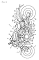
- is a left side view showing a motorcycle according to an embodiment;
- Fig. 2
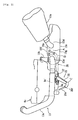
- is a left side view showing an exhaust device and a side stand part of the motorcycle;
- Fig. 3
- is a plan view showing the exhaust device and the side stand part;
- Fig. 4
- is a view showing the side stand part as viewed from the rear of a vehicle;
- Fig. 5
- is a view showing the side stand as viewed from laterally of a vehicle;
- Fig. 6
- is a cross sectional view (cross sectional view taken along the line VI-VI in
Fig. 5 ) showing the side stand; - Fig. 7
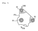
- is a view showing a mount flange portion of the side stand as viewed from laterally of a vehicle; and
- Fig. 8
- is a cross sectional view (cross sectional view taken along the line VIII-VIII in
Fig. 7 ) showing the mount flange portion. - Among others, the following reference signs are used in the figures:
- 1: motorcycle
- 2: body frame
- 8: engine
- 8c': side wall portion
- 13: exhaust device
- 13a: exhaust pipe
- 13c: exhaust chamber (displacement chamber)
- 13e: muffler
- 21: side stand
- 26: stand body
- 26a: connection
- 26e: foot put portion
- 26f: tip end
- 27: stand bracket
- 27a: mount flange portion
- 27b: support portion
- 27c: support surface
- 28: rotating shaft
- 28a: journal portion
- 28b: load receiving portion
- A: recess
- B: road surface
- C: service position
- D: storage position
- An embodiment will be described below with reference to the accompanying drawings.
-
Figs. 1 to 8 are views illustrating a motorcycle according to an embodiment. In addition, front and rear, and left and right referred to in descriptions of the embodiment mean front and rear, and left and right as seen in a state of being seated on a seat unless otherwise specified. - In the drawings, the reference numeral 1 denotes a motorcycle, the motorcycle 1 having the following outline construction. A head pipe 2a at a front end of a
body frame 2 supports afront fork 3 to make the same steerable left and right. Afront wheel 4 is journaled at a lower end of thefront fork 3, and thefront wheel 4 is covered by afront fender 5, thefront fender 5 being mounted to a lower portion of thefront fork 3. Also, thefront fork 3 has a headlight device 6 arranged on an upper portion thereof and has a steering handle 7 fixed at an upper end thereof. - Also, the
body frame 2 has anengine unit 8 suspended by afront suspension bracket 9, a central suspension bracket 10, and a rear arm bracket portion 2b of thebody frame 2. Anintake device 12 and anexhaust device 13 are connected to theengine unit 8 and aradiator device 14 is arranged forwardly of the engine unit. Aframe cover 15 covers theintake device 12 from above and anindicator device 16 representative of a vehicular state is arranged on theframe cover 15. - Also, a
side stand 21 is arranged on a left wall lower portion of theengine unit 8 to have the motorcycle 1 uprising in a state of being a little inclined leftward. - Furthermore, the rear arm bracket portion 2b of the
body frame 2 supports arear arm 17 to enable the same to swing vertically and arear wheel 18 is supported at a rear end of therear arm 17. Therear wheel 18 and thefront wheel 4 are braked by ahydraulic brake device 22. - A
rear wheel suspension 19 is arranged between therear arm 17 and the rear arm bracket portion 2b, therear wheel suspension 19 comprising a remote type operatingcharacteristics adjustment mechanism 25. - A
fuel tank 20 is arranged above therear wheel suspension 19. Ahydraulic control unit 22a of thebrake device 22 is arranged forwardly of and obliquely upwardly of thefuel tank 20. Amain seat 23a is arranged to cover upper portions of thehydraulic control unit 22a and thefuel tank 20, and atandem seat 23b is arranged contiguous to themain seat 23a. In addition, thereference numeral 23c denotes a backrest that supports a rider's waist. Further, arear fender 24 that covers therear wheel 18 from above is arranged below thetandem seat 23b. - The
engine unit 8 is of a water-cooled four-stroke V-type four-cylinder engine arranging left and right,front cylinders 8a and left and right,rear cylinders 8b on a crankcase 8c to define a V bank in a longitudinal direction. Anoil pan 8d is connected to a bottom surface of thecrank case 8c. - The
exhaust device 13 includes afront exhaust pipe 13a connected to thefront cylinder 8a of theengine unit 8, arear exhaust pipe 13b connected to therear cylinder 8b, an exhaust chamber (displacement chamber) 13bc, to which therespective exhaust pipes right mufflers side wall 13d of theexhaust chamber 13c to extend rearward and obliquely upward on both the left and right of the vehicle. - Here, the
exhaust chamber 13c is in the form of a flat box including anupper wall 13f and alower wall 13g, which are formed substantially flat, and aside wall 13d arranged to surround peripheries of the both walls, the exhaust chamber being arranged below a front portion of therear arm 17 and between therear wheel 18 and a bottom of theengine unit 8. - Here, the
rear exhaust pipe 13b extends rearward from therear cylinder 8b and bends downward to be connected to a front portion of theupper wall 13f of theexhaust chamber 13c. On the other hand, thefront exhaust pipe 13a extends rearward and obliquely downward while diverging a little outward from thefront cylinder 8a and bends rearward to extend rearward along aside wall portion 8c' of thecrank case 8c. Arear end 13a' of thefront exhaust pipe 13a is connected to a front portion of theside wall 13d of theexhaust chamber 13c while bending arcuately inward in a vehicle width direction. - Furthermore, the left and
right mufflers side wall 13d of theexhaust chamber 13c and itsconnection 13e' projects in the vehicle width direction. Consequently, a recess A dented inward in the vehicle width direction is formed at a connection of theexhaust chamber 13c to the left,front exhaust pipe 13a and theleft muffler 13e. - The side stand 21 mainly includes a
stand body 26 grounded on the road surface B and astand bracket 27 that supports thestand body 26 to enable the same to turn between a service position C and a storage position D. - The
stand bracket 27 is mounted to theside wall portion 8c' of thecrank case 8c. More specifically, thestand bracket 27 comprises amount flange portion 27a mounted to theside wall portion 8c', asupport portion 27b formed integral with themount flange portion 27a to support thestand body 26, and arotating shaft 28 fixed to thesupport portion 27b to project obliquely downward on an opposite side to theexhaust pipe 13a. - The
mount flange portion 27a is in the form of a substantially triangular-shaped thick plate fixed to amount bearing surface 8e, which is formed flat on theside wall portion 8c', by threebolts 33 inserted into corners of the triangle. Thesupport portion 27b is in the form of a thick plate bent a little inward in the vehicle width direction and obliquely downward from a lower edge of themount flange portion 27a and having aflat support surface 27c at a tip end thereof. - The rotating
shaft 28 is fixed to thesupport portion 27b to extend inward in the vehicle width direction and obliquely downward as a whole. The rotatingshaft 28 includes ajournal portion 28a that journals aconnection 26a of thestand body 26, a load receiving portion 28b having a larger diameter than that of thejournal portion 28a, and abolt portion 28c projecting outward in the vehicle width direction and obliquely upward from the load receiving portion 28b, and is clamped and fixed to thesupport portion 27b by anut 28d. - The
stand body 26 is rod-shaped and formed at a base end thereof with theconnection 26a. Theconnection 26a is formed with anaxial hole 26b and a bearingmetal 26c is fitted onto an inner surface thereof. Theaxial hole 26b is fitted rotatably onto thejournal portion 28a of therotating shaft 28. Also, a foot putportion 26e, on which a user puts the foot when turning thestand body 26, is formed at atip end 26f of thestand body 26. The foot putportion 26e is formed to come up a little from the road surface B when thestand body 26 is in the service position C, thus making it easy for a user to put the foot thereon. - A
stationary plate 29 is fitted onto a tip end of thejournal portion 28a in a manner not to enable relative turning and fixed through awasher 30a by abolt 30 whereby thestand body 26 is held on thejournal portion 28a to be able to turn. - Also, a
latch pin 29a is fixed to thestationary plate 29 and oneend 31 a of acoil spring 31 is latched on thelatch pin 29a through alink plate 29b. Theother end 31 b of thecoil spring 31 is latched on aprojection 26d formed midway thestand body 26. Thecoil spring 31 provides for bias toward the service position C when thestand body 26 is turned to the service position C and provides for bias toward the storage position D when turned to the storage position D. - Also, a
switch boss portion 27d is formed integral with thesupport portion 27b and astand switch 32 is mounted to theswitch boss portion 27d. In order to prevent starting in a state, in which thestand body 26 is in the service position C, thestand switch 32 is constructed to detect a position of thestand body 26. - Here, when the
stand body 26 is in the storage position D, a part 26' of thestand body 26 intersects therear end 13a' of thefront exhaust pipe 13a as viewed in plan view of a vehicle and thetip end 26f of thestand body 26 and a part of the foot putportion 26e are positioned in the recess A. Also, as viewed from laterally of a vehicle, thetip end 26f of thestand body 26 and the foot putportion 26e overlap the recess A. - As described above, according to the embodiment, the side stand 21 is mounted to the
side wall portion 8c' so as to be positioned between theexhaust pipe 13a and theside wall portion 8c' of the engine, so that a bank angle is easy to ensure and it is accordingly possible to improve freedom in a configuration position in a height direction of the exhaust pipe. - That is, in the case where a side stand is mounted to a downtube arranged laterally of an engine side wall portion and an exhaust pipe is arranged outwardly thereof, the exhaust pipe is outward away from a vehicle center line in a vehicle width direction, so that the exhaust pipe is made easy to ground when a vehicle is caused to bank. Therefore, in order to ensure a large bank angle, an exhaust pipe cannot but be made high in a configuration position. According to the embodiment, the side stand 21 is mounted directly to the
side wall portion 8c' and no downtube is present, so that it is possible to arrange thefront exhaust pipe 13a toward a vehicle center line and so the front exhaust pipe is hard to ground at the time of banking. Therefore, it is also possible to arrange thefront exhaust pipe 13a in a low location and so freedom in a configuration position is high correspondingly. - Also, since the side stand 21 is constructed to comprise the
stand body 26 and thestand bracket 27 that supports the stand body to enable the same to turn, and thestand bracket 27 is mounted to theside wall portion 8c', it is possible in a simple construction to arrange the side stand 21 between thefront exhaust pipe 13a and theside wall portion 8c'. - Furthermore, the
stand bracket 27 is constructed to comprise thesupport portion 27b including thesupport surface 27c positioned on an opposite side to theexhaust pipe 13a and thestand body 26 is arranged to abut against thesupport surface 27c, so that it is possible to arrange thestand body 26 in a low location. Correspondingly, it is possible to arrange theexhaust pipe 13a in a low location, thus enabling further enlarging theexhaust pipe 13a in freedom with respect to a configuration position. - Also, since the rotating
shaft 28 having thejournal portion 28a of large diameter is fixed to thesupport portion 27b, thejournal portion 28a journals theconnection 26a of thestand body 26, and the load receiving portion 28b having a larger diameter than that of thejournal portion 28a is caused to abut against thesupport surface 27c, it is possible to withstand a large load generating on the journal portion in the case where thestand body 26 abuts against a lower surface of thesupport portion 27b. - Also, since when the
stand body 26 is in the storage position D, thestand body 26 and theexhaust pipe 13a intersect each other as viewed in plan view, the foot putportion 26e can be made to project outward although the side stand 21 is arranged between theexhaust pipe 13a and theside wall portion 8c'. Besides, when thestand body 26 is in the storage position D, thetip end 26f of thestand body 26 and the part of the foot putportion 26e are positioned in the recess A as viewed in plan view, so that degradation in outward appearance, which the foot putportion 26e projects outward more than needed to cause, is not brought about and so it is possible to readily perform an operation when thestand body 26 is turned to the service position C from the storage position D. - Furthermore, when the
stand body 26 is in the storage position D, thetip end 26f of thestand body 26 and the foot putportion 26e overlap the recess A as viewed from laterally of a vehicle, so that the foot putportion 26e or the like becomes hard to stand out in a stored state in this respect and so it is possible to achieve an improvement in outward appearance. - In addition, while the embodiment has been described with respect to the case where the side stand 21 is arranged on the left of a vehicle, some side stands are provided on the right according to countries and the technical teaching above is also applicable in such case.
- The description above discloses (among others) an embodiment of a motorcycle comprising a body frame, an engine mounted to the body frame, an exhaust device connected to the engine, and a side stand that uprises the vehicle in a state of being inclined in a vehicle width direction, and wherein the exhaust device includes an exhaust pipe disposed laterally of a side wall portion of the engine to extend rearwardly of the vehicle, and the side stand is mounted to the side wall portion to be positioned between the exhaust pipe and the side wall portion of the engine.
- Preferably, the side stand includes a stand body that grounds a road surface, and a stand bracket that supports the stand body to enable the same to turn between a service position and a storage position, and the stand bracket is mounted to the side wall portion of the engine.
- Further, preferably the stand bracket includes a mount flange portion mounted to the side wall portion of the engine, a support portion that supports the stand body, and a rotating shaft fixed to the support portion to project on an opposite side to the exhaust pipe, and the stand body is arranged to abut against a support surface of the support portion formed on an opposite side to the exhaust pipe, and supported by the rotating shaft to be able to turn.
- Further, preferably the stand body includes a connection connected to the stand bracket, and the rotating shaft includes a journal portion that journals the connection, and a load receiving portion that abuts against the support surface.
- Further, preferably the load receiving portion is formed to have a larger diameter than that of the journal portion.
- Further, preferably when the stand body is in the storage position, the stand body and the exhaust pipe intersect each other as viewed in plan view.
- Further, preferably the exhaust device includes a recess disposed intermediately of an exhaust path to be dented inward in a vehicle width direction, and when the stand body is in the storage position, a tip end of the stand body overlaps the recess as viewed from laterally.
- Further, preferably the exhaust device includes a recess disposed intermediately of an exhaust path to be dented inward in a vehicle width direction, and when the stand body is in the storage position, a tip end of the stand body is positioned in the recess as viewed in plan view.
- Further, preferably the exhaust device further includes a displacement chamber, to which the exhaust pipe is connected, and the recess is formed at a connection of the displacement chamber and the exhaust pipe.
- Further, preferably a muffler is connected to the displacement chamber, and the recess is formed at a connection of the displacement chamber to the exhaust pipe and the muffler.
- In order to provide a motorcycle, in which a side stand is improved in a configuration position to enable ensuring the freedom of an exhaust pipe in a configuration position, an embodiment of a motorcycle 1 comprises a
body frame 2, anengine 8 mounted to thebody frame 2, anexhaust device 13 connected to the engine, and aside stand 21 that uprises the vehicle in a state of being inclined in a vehicle width direction, and wherein theexhaust device 13 includes anexhaust pipe 13a disposed laterally of aside wall portion 8c' of the engine to extend rearwardly of the vehicle, and the side stand 21 is mounted to theside wall portion 8c' to be positioned between theexhaust pipe 13a and theside wall portion 8c' of the engine.
Claims (14)
- Motorcycle comprising:a body frame (2),an engine (8) mounted to the body frame (2), said engine (8) having a side wall portion (8c'),an exhaust device (13) connected to the engine (8), said exhaust device (13) including an exhaust pipe (13a), anda side stand (21) configured to uprise the motorcycle in a state when being inclined in motorcycle width direction, whereinthe side stand (21) is mounted to the side wall portion (8c') of the engine (8) between the exhaust pipe (13a) and the side wall portion (8c').
- Motorcycle according to claim 1, wherein the exhaust device (13a) is disposed laterally of the side wall portion (8c') of the engine (8) and extends in moving direction of the motorcycle rearwardly.
- Motorcycle according to claim 1 or 2, wherein the side stand (21) includes a stand body (26) configured to ground a road surface and a stand bracket (27) supporting the stand body (26) to enable the same to turn between a service position (C) and a storage position (D), and the stand bracket (27) is mounted to the side wall portion (8c') of the engine (8).
- Motorcycle according to claim 3, wherein the stand bracket (27) includes a mount flange portion (27a) mounted to the side wall portion (8c') of the engine (8), a support portion (27b) supporting the stand body (26), the stand body (26) being turnably supported by a rotating shaft (28) fixed to the support portion (27b).
- Motorcycle according to claim 4, wherein the rotating shaft (28) projects from the support portion (27b) on an opposite side with regard to the exhaust pipe (13a), and/or the stand body (26) is arranged to abut against a support surface (27c) of the support portion (27b) formed on an opposite side with regard to the exhaust pipe (13a).
- Motorcycle according to one of claims 3 to 5, wherein the stand body (26) includes a connection (26a) connected to the stand bracket (27), and, preferably, the rotating shaft (28) includes a journal portion (28a) that journals the connection (26a).
- Motorcycle according to claim 5 or 6, wherein the rotating shaft (28) includes a load receiving portion (28b) that abuts against the support surface (27c).
- Motorcycle according to claim 7, wherein the load receiving portion (28b) has a larger diameter than a diameter of the journal portion (28a).
- Motorcycle according to one of claims 1 to 8, wherein when the stand body (26) is in its storage position (D), the stand body (26) and the exhaust pipe (13a) intersect each other as viewed in plan view.
- Motorcycle according to one of claims 1 to 9, wherein the exhaust device (13) includes a recess (A) disposed intermediately of an exhaust path to be dented inward in a motorcycle width direction.
- Motorcycle according to claim 10, wherein when the stand body (26) is in its storage position (D), a tip end (26f) of the stand body (26) overlaps the recess (A) as viewed laterally.
- Motorcycle according to claim 10 or 11, wherein when the stand body (26) is in its storage position (D), a tip end (26f) of the stand body (26) is positioned in the recess (A) as viewed in plan view.
- Motorcycle according to one of claims 1 to 12, wherein the exhaust device (13) further includes a displacement chamber (13c), to which the exhaust pipe (13a) is connected, and, preferably, the recess (A) is formed at a connection of the displacement chamber (13c) and the exhaust pipe (13a).
- Motorcycle according to claim 13, wherein a muffler (13e) is connected to the displacement chamber (13c), and, preferably, the recess (A) is formed at a connection of the displacement chamber (13c) to the exhaust pipe (13a) and the muffler (13e).
Applications Claiming Priority (1)
| Application Number | Priority Date | Filing Date | Title |
|---|---|---|---|
| JP2007264953A JP2009090890A (en) | 2007-10-10 | 2007-10-10 | Motorcycle |
Publications (3)
| Publication Number | Publication Date |
|---|---|
| EP2048066A2 true EP2048066A2 (en) | 2009-04-15 |
| EP2048066A3 EP2048066A3 (en) | 2009-12-23 |
| EP2048066B1 EP2048066B1 (en) | 2010-12-15 |
Family
ID=40000890
Family Applications (1)
| Application Number | Title | Priority Date | Filing Date |
|---|---|---|---|
| EP08017827A Active EP2048066B1 (en) | 2007-10-10 | 2008-10-10 | Motorcycle |
Country Status (4)
| Country | Link |
|---|---|
| EP (1) | EP2048066B1 (en) |
| JP (1) | JP2009090890A (en) |
| AT (1) | ATE491627T1 (en) |
| DE (1) | DE602008003960D1 (en) |
Citations (1)
| Publication number | Priority date | Publication date | Assignee | Title |
|---|---|---|---|---|
| JPH03187075A (en) | 1989-12-16 | 1991-08-15 | Mitsubishi Electric Corp | Supporting structure for magnetic head holding core slider |
Family Cites Families (9)
| Publication number | Priority date | Publication date | Assignee | Title |
|---|---|---|---|---|
| JPS5747262A (en) * | 1980-09-04 | 1982-03-18 | Yamaha Motor Co Ltd | Preventive device for forgetting of return of side stand for autobicycle |
| JPS5949314A (en) * | 1982-09-14 | 1984-03-21 | Honda Motor Co Ltd | Exhaust apparatus for motorcycle |
| JPH07102835B2 (en) * | 1984-12-18 | 1995-11-08 | ヤマハ発動機株式会社 | Motorcycle exhaust system |
| JPS61160378A (en) * | 1985-01-08 | 1986-07-21 | ヤマハ発動機株式会社 | Side stand support structure of motorcycle |
| JP3187075B2 (en) * | 1991-05-13 | 2001-07-11 | 本田技研工業株式会社 | Side stand mounting structure for motorcycles |
| JP4280401B2 (en) * | 2000-07-19 | 2009-06-17 | 本田技研工業株式会社 | Engine exhaust system support structure for motorcycles |
| KR100396407B1 (en) * | 2001-03-08 | 2003-09-03 | 대림자동차공업주식회사 | Safety device for motorcycle |
| JP4194036B2 (en) * | 2003-12-03 | 2008-12-10 | 本田技研工業株式会社 | Auto idle stop vehicle |
| JP2006315657A (en) * | 2005-07-05 | 2006-11-24 | Honda Motor Co Ltd | Arrangement structure of motorcycle muffler and brake pedal |
-
2007
- 2007-10-10 JP JP2007264953A patent/JP2009090890A/en active Pending
-
2008
- 2008-10-10 EP EP08017827A patent/EP2048066B1/en active Active
- 2008-10-10 AT AT08017827T patent/ATE491627T1/en not_active IP Right Cessation
- 2008-10-10 DE DE602008003960T patent/DE602008003960D1/en active Active
Patent Citations (1)
| Publication number | Priority date | Publication date | Assignee | Title |
|---|---|---|---|---|
| JPH03187075A (en) | 1989-12-16 | 1991-08-15 | Mitsubishi Electric Corp | Supporting structure for magnetic head holding core slider |
Also Published As
| Publication number | Publication date |
|---|---|
| EP2048066A3 (en) | 2009-12-23 |
| JP2009090890A (en) | 2009-04-30 |
| ATE491627T1 (en) | 2011-01-15 |
| DE602008003960D1 (en) | 2011-01-27 |
| EP2048066B1 (en) | 2010-12-15 |
Similar Documents
| Publication | Publication Date | Title |
|---|---|---|
| US8757314B2 (en) | Chain drive for saddle-ride type vehicle | |
| JP2010030584A (en) | Motorcycle | |
| JP3154590U (en) | Motorcycle | |
| JP6117590B2 (en) | Fuel tank structure for saddle-ride type vehicles | |
| JP5067297B2 (en) | Rear brake device arrangement structure and motorcycle | |
| EP1783041A1 (en) | Straddle-type vehicle | |
| JP5323533B2 (en) | Saddle riding | |
| JP2006315504A (en) | Motorcycle exhaust system | |
| EP2159147A2 (en) | Motorcycle with inclination sensor | |
| EP2332762A1 (en) | Servo motor layout structure of saddle-ride type vehicle | |
| JP2020050306A (en) | Steering structure of saddle-riding type vehicle | |
| EP2048066B1 (en) | Motorcycle | |
| JP2007137408A (en) | Saddle riding | |
| JP2019018758A (en) | Front part structure of straddle-type vehicle | |
| JP4577806B2 (en) | Body structure of motorcycle | |
| JP5177305B2 (en) | Rear brake device arrangement structure and motorcycle | |
| CN106364603A (en) | Straddling type vehicle | |
| JP3158807U (en) | Motorcycle | |
| JP4685527B2 (en) | Motorcycle exhaust system | |
| JP2009196497A (en) | Motorcycle | |
| JP2021011850A (en) | Radiator for saddle-mounted vehicle | |
| JP4761984B2 (en) | Motorcycle | |
| JP2006315657A (en) | Arrangement structure of motorcycle muffler and brake pedal | |
| JP3157691U (en) | Saddle riding vehicle | |
| JP2009090891A (en) | Saddle riding vehicle |
Legal Events
| Date | Code | Title | Description |
|---|---|---|---|
| PUAI | Public reference made under article 153(3) epc to a published international application that has entered the european phase |
Free format text: ORIGINAL CODE: 0009012 |
|
| AK | Designated contracting states |
Kind code of ref document: A2 Designated state(s): AT BE BG CH CY CZ DE DK EE ES FI FR GB GR HR HU IE IS IT LI LT LU LV MC MT NL NO PL PT RO SE SI SK TR |
|
| AX | Request for extension of the european patent |
Extension state: AL BA MK RS |
|
| PUAL | Search report despatched |
Free format text: ORIGINAL CODE: 0009013 |
|
| AK | Designated contracting states |
Kind code of ref document: A3 Designated state(s): AT BE BG CH CY CZ DE DK EE ES FI FR GB GR HR HU IE IS IT LI LT LU LV MC MT NL NO PL PT RO SE SI SK TR |
|
| AX | Request for extension of the european patent |
Extension state: AL BA MK RS |
|
| 17P | Request for examination filed |
Effective date: 20091203 |
|
| 17Q | First examination report despatched |
Effective date: 20100107 |
|
| RIN1 | Information on inventor provided before grant (corrected) |
Inventor name: ITO, NORIMASA |
|
| GRAP | Despatch of communication of intention to grant a patent |
Free format text: ORIGINAL CODE: EPIDOSNIGR1 |
|
| RAP1 | Party data changed (applicant data changed or rights of an application transferred) |
Owner name: YAMAHA HATSUDOKI KABUSHIKI KAISHA |
|
| AKX | Designation fees paid |
Designated state(s): AT BE BG CH CY CZ DE DK EE ES FI FR GB GR HR HU IE IS IT LI LT LU LV MC MT NL NO PL PT RO SE SI SK TR |
|
| GRAS | Grant fee paid |
Free format text: ORIGINAL CODE: EPIDOSNIGR3 |
|
| GRAA | (expected) grant |
Free format text: ORIGINAL CODE: 0009210 |
|
| AK | Designated contracting states |
Kind code of ref document: B1 Designated state(s): AT BE BG CH CY CZ DE DK EE ES FI FR GB GR HR HU IE IS IT LI LT LU LV MC MT NL NO PL PT RO SE SI SK TR |
|
| REG | Reference to a national code |
Ref country code: GB Ref legal event code: FG4D Ref country code: CH Ref legal event code: EP |
|
| REG | Reference to a national code |
Ref country code: IE Ref legal event code: FG4D |
|
| REF | Corresponds to: |
Ref document number: 602008003960 Country of ref document: DE Date of ref document: 20110127 Kind code of ref document: P |
|
| REG | Reference to a national code |
Ref country code: NL Ref legal event code: VDEP Effective date: 20101215 |
|
| PG25 | Lapsed in a contracting state [announced via postgrant information from national office to epo] |
Ref country code: LT Free format text: LAPSE BECAUSE OF FAILURE TO SUBMIT A TRANSLATION OF THE DESCRIPTION OR TO PAY THE FEE WITHIN THE PRESCRIBED TIME-LIMIT Effective date: 20101215 Ref country code: NO Free format text: LAPSE BECAUSE OF FAILURE TO SUBMIT A TRANSLATION OF THE DESCRIPTION OR TO PAY THE FEE WITHIN THE PRESCRIBED TIME-LIMIT Effective date: 20110315 |
|
| LTIE | Lt: invalidation of european patent or patent extension |
Effective date: 20101215 |
|
| PG25 | Lapsed in a contracting state [announced via postgrant information from national office to epo] |
Ref country code: FI Free format text: LAPSE BECAUSE OF FAILURE TO SUBMIT A TRANSLATION OF THE DESCRIPTION OR TO PAY THE FEE WITHIN THE PRESCRIBED TIME-LIMIT Effective date: 20101215 Ref country code: SI Free format text: LAPSE BECAUSE OF FAILURE TO SUBMIT A TRANSLATION OF THE DESCRIPTION OR TO PAY THE FEE WITHIN THE PRESCRIBED TIME-LIMIT Effective date: 20101215 Ref country code: BG Free format text: LAPSE BECAUSE OF FAILURE TO SUBMIT A TRANSLATION OF THE DESCRIPTION OR TO PAY THE FEE WITHIN THE PRESCRIBED TIME-LIMIT Effective date: 20110315 Ref country code: CY Free format text: LAPSE BECAUSE OF FAILURE TO SUBMIT A TRANSLATION OF THE DESCRIPTION OR TO PAY THE FEE WITHIN THE PRESCRIBED TIME-LIMIT Effective date: 20101215 Ref country code: LV Free format text: LAPSE BECAUSE OF FAILURE TO SUBMIT A TRANSLATION OF THE DESCRIPTION OR TO PAY THE FEE WITHIN THE PRESCRIBED TIME-LIMIT Effective date: 20101215 Ref country code: HR Free format text: LAPSE BECAUSE OF FAILURE TO SUBMIT A TRANSLATION OF THE DESCRIPTION OR TO PAY THE FEE WITHIN THE PRESCRIBED TIME-LIMIT Effective date: 20101215 Ref country code: SE Free format text: LAPSE BECAUSE OF FAILURE TO SUBMIT A TRANSLATION OF THE DESCRIPTION OR TO PAY THE FEE WITHIN THE PRESCRIBED TIME-LIMIT Effective date: 20101215 Ref country code: AT Free format text: LAPSE BECAUSE OF FAILURE TO SUBMIT A TRANSLATION OF THE DESCRIPTION OR TO PAY THE FEE WITHIN THE PRESCRIBED TIME-LIMIT Effective date: 20101215 Ref country code: NL Free format text: LAPSE BECAUSE OF FAILURE TO SUBMIT A TRANSLATION OF THE DESCRIPTION OR TO PAY THE FEE WITHIN THE PRESCRIBED TIME-LIMIT Effective date: 20101215 |
|
| PG25 | Lapsed in a contracting state [announced via postgrant information from national office to epo] |
Ref country code: GR Free format text: LAPSE BECAUSE OF FAILURE TO SUBMIT A TRANSLATION OF THE DESCRIPTION OR TO PAY THE FEE WITHIN THE PRESCRIBED TIME-LIMIT Effective date: 20110316 Ref country code: PT Free format text: LAPSE BECAUSE OF FAILURE TO SUBMIT A TRANSLATION OF THE DESCRIPTION OR TO PAY THE FEE WITHIN THE PRESCRIBED TIME-LIMIT Effective date: 20110415 Ref country code: BE Free format text: LAPSE BECAUSE OF FAILURE TO SUBMIT A TRANSLATION OF THE DESCRIPTION OR TO PAY THE FEE WITHIN THE PRESCRIBED TIME-LIMIT Effective date: 20101215 Ref country code: ES Free format text: LAPSE BECAUSE OF FAILURE TO SUBMIT A TRANSLATION OF THE DESCRIPTION OR TO PAY THE FEE WITHIN THE PRESCRIBED TIME-LIMIT Effective date: 20110326 Ref country code: IS Free format text: LAPSE BECAUSE OF FAILURE TO SUBMIT A TRANSLATION OF THE DESCRIPTION OR TO PAY THE FEE WITHIN THE PRESCRIBED TIME-LIMIT Effective date: 20110415 Ref country code: EE Free format text: LAPSE BECAUSE OF FAILURE TO SUBMIT A TRANSLATION OF THE DESCRIPTION OR TO PAY THE FEE WITHIN THE PRESCRIBED TIME-LIMIT Effective date: 20101215 Ref country code: CZ Free format text: LAPSE BECAUSE OF FAILURE TO SUBMIT A TRANSLATION OF THE DESCRIPTION OR TO PAY THE FEE WITHIN THE PRESCRIBED TIME-LIMIT Effective date: 20101215 |
|
| PG25 | Lapsed in a contracting state [announced via postgrant information from national office to epo] |
Ref country code: SK Free format text: LAPSE BECAUSE OF FAILURE TO SUBMIT A TRANSLATION OF THE DESCRIPTION OR TO PAY THE FEE WITHIN THE PRESCRIBED TIME-LIMIT Effective date: 20101215 Ref country code: RO Free format text: LAPSE BECAUSE OF FAILURE TO SUBMIT A TRANSLATION OF THE DESCRIPTION OR TO PAY THE FEE WITHIN THE PRESCRIBED TIME-LIMIT Effective date: 20101215 Ref country code: PL Free format text: LAPSE BECAUSE OF FAILURE TO SUBMIT A TRANSLATION OF THE DESCRIPTION OR TO PAY THE FEE WITHIN THE PRESCRIBED TIME-LIMIT Effective date: 20101215 |
|
| PLBE | No opposition filed within time limit |
Free format text: ORIGINAL CODE: 0009261 |
|
| STAA | Information on the status of an ep patent application or granted ep patent |
Free format text: STATUS: NO OPPOSITION FILED WITHIN TIME LIMIT |
|
| PG25 | Lapsed in a contracting state [announced via postgrant information from national office to epo] |
Ref country code: DK Free format text: LAPSE BECAUSE OF FAILURE TO SUBMIT A TRANSLATION OF THE DESCRIPTION OR TO PAY THE FEE WITHIN THE PRESCRIBED TIME-LIMIT Effective date: 20101215 |
|
| 26N | No opposition filed |
Effective date: 20110916 |
|
| PG25 | Lapsed in a contracting state [announced via postgrant information from national office to epo] |
Ref country code: IT Free format text: LAPSE BECAUSE OF FAILURE TO SUBMIT A TRANSLATION OF THE DESCRIPTION OR TO PAY THE FEE WITHIN THE PRESCRIBED TIME-LIMIT Effective date: 20101215 |
|
| REG | Reference to a national code |
Ref country code: DE Ref legal event code: R097 Ref document number: 602008003960 Country of ref document: DE Effective date: 20110916 |
|
| PG25 | Lapsed in a contracting state [announced via postgrant information from national office to epo] |
Ref country code: MC Free format text: LAPSE BECAUSE OF NON-PAYMENT OF DUE FEES Effective date: 20111031 |
|
| REG | Reference to a national code |
Ref country code: IE Ref legal event code: MM4A |
|
| PG25 | Lapsed in a contracting state [announced via postgrant information from national office to epo] |
Ref country code: IE Free format text: LAPSE BECAUSE OF NON-PAYMENT OF DUE FEES Effective date: 20111010 |
|
| PG25 | Lapsed in a contracting state [announced via postgrant information from national office to epo] |
Ref country code: MT Free format text: LAPSE BECAUSE OF FAILURE TO SUBMIT A TRANSLATION OF THE DESCRIPTION OR TO PAY THE FEE WITHIN THE PRESCRIBED TIME-LIMIT Effective date: 20101215 |
|
| PG25 | Lapsed in a contracting state [announced via postgrant information from national office to epo] |
Ref country code: LU Free format text: LAPSE BECAUSE OF NON-PAYMENT OF DUE FEES Effective date: 20111010 |
|
| REG | Reference to a national code |
Ref country code: CH Ref legal event code: PL |
|
| PG25 | Lapsed in a contracting state [announced via postgrant information from national office to epo] |
Ref country code: CH Free format text: LAPSE BECAUSE OF NON-PAYMENT OF DUE FEES Effective date: 20121031 Ref country code: LI Free format text: LAPSE BECAUSE OF NON-PAYMENT OF DUE FEES Effective date: 20121031 |
|
| PG25 | Lapsed in a contracting state [announced via postgrant information from national office to epo] |
Ref country code: TR Free format text: LAPSE BECAUSE OF FAILURE TO SUBMIT A TRANSLATION OF THE DESCRIPTION OR TO PAY THE FEE WITHIN THE PRESCRIBED TIME-LIMIT Effective date: 20101215 |
|
| PG25 | Lapsed in a contracting state [announced via postgrant information from national office to epo] |
Ref country code: HU Free format text: LAPSE BECAUSE OF FAILURE TO SUBMIT A TRANSLATION OF THE DESCRIPTION OR TO PAY THE FEE WITHIN THE PRESCRIBED TIME-LIMIT Effective date: 20101215 |
|
| REG | Reference to a national code |
Ref country code: FR Ref legal event code: PLFP Year of fee payment: 8 |
|
| REG | Reference to a national code |
Ref country code: FR Ref legal event code: PLFP Year of fee payment: 9 |
|
| REG | Reference to a national code |
Ref country code: FR Ref legal event code: PLFP Year of fee payment: 10 |
|
| REG | Reference to a national code |
Ref country code: FR Ref legal event code: PLFP Year of fee payment: 11 |
|
| PGFP | Annual fee paid to national office [announced via postgrant information from national office to epo] |
Ref country code: FR Payment date: 20201022 Year of fee payment: 13 Ref country code: GB Payment date: 20201022 Year of fee payment: 13 |
|
| GBPC | Gb: european patent ceased through non-payment of renewal fee |
Effective date: 20211010 |
|
| PG25 | Lapsed in a contracting state [announced via postgrant information from national office to epo] |
Ref country code: GB Free format text: LAPSE BECAUSE OF NON-PAYMENT OF DUE FEES Effective date: 20211010 |
|
| PG25 | Lapsed in a contracting state [announced via postgrant information from national office to epo] |
Ref country code: FR Free format text: LAPSE BECAUSE OF NON-PAYMENT OF DUE FEES Effective date: 20211031 |
|
| P01 | Opt-out of the competence of the unified patent court (upc) registered |
Effective date: 20230527 |
|
| PGFP | Annual fee paid to national office [announced via postgrant information from national office to epo] |
Ref country code: DE Payment date: 20251021 Year of fee payment: 18 |