EP2047929A1 - Work machining apparatus control program and work machining apparatus controller for executing the control program - Google Patents
Work machining apparatus control program and work machining apparatus controller for executing the control program Download PDFInfo
- Publication number
- EP2047929A1 EP2047929A1 EP07791725A EP07791725A EP2047929A1 EP 2047929 A1 EP2047929 A1 EP 2047929A1 EP 07791725 A EP07791725 A EP 07791725A EP 07791725 A EP07791725 A EP 07791725A EP 2047929 A1 EP2047929 A1 EP 2047929A1
- Authority
- EP
- European Patent Office
- Prior art keywords
- work
- machining
- program
- main spindle
- program block
- Prior art date
- Legal status (The legal status is an assumption and is not a legal conclusion. Google has not performed a legal analysis and makes no representation as to the accuracy of the status listed.)
- Granted
Links
Images








Classifications
-
- B—PERFORMING OPERATIONS; TRANSPORTING
- B23—MACHINE TOOLS; METAL-WORKING NOT OTHERWISE PROVIDED FOR
- B23Q—DETAILS, COMPONENTS, OR ACCESSORIES FOR MACHINE TOOLS, e.g. ARRANGEMENTS FOR COPYING OR CONTROLLING; MACHINE TOOLS IN GENERAL CHARACTERISED BY THE CONSTRUCTION OF PARTICULAR DETAILS OR COMPONENTS; COMBINATIONS OR ASSOCIATIONS OF METAL-WORKING MACHINES, NOT DIRECTED TO A PARTICULAR RESULT
- B23Q39/00—Metal-working machines incorporating a plurality of sub-assemblies, each capable of performing a metal-working operation
- B23Q39/04—Metal-working machines incorporating a plurality of sub-assemblies, each capable of performing a metal-working operation the sub-assemblies being arranged to operate simultaneously at different stations, e.g. with an annular work-table moved in steps
-
- B—PERFORMING OPERATIONS; TRANSPORTING
- B23—MACHINE TOOLS; METAL-WORKING NOT OTHERWISE PROVIDED FOR
- B23B—TURNING; BORING
- B23B1/00—Methods for turning or working essentially requiring the use of turning-machines; Use of auxiliary equipment in connection with such methods
-
- B—PERFORMING OPERATIONS; TRANSPORTING
- B23—MACHINE TOOLS; METAL-WORKING NOT OTHERWISE PROVIDED FOR
- B23Q—DETAILS, COMPONENTS, OR ACCESSORIES FOR MACHINE TOOLS, e.g. ARRANGEMENTS FOR COPYING OR CONTROLLING; MACHINE TOOLS IN GENERAL CHARACTERISED BY THE CONSTRUCTION OF PARTICULAR DETAILS OR COMPONENTS; COMBINATIONS OR ASSOCIATIONS OF METAL-WORKING MACHINES, NOT DIRECTED TO A PARTICULAR RESULT
- B23Q15/00—Automatic control or regulation of feed movement, cutting velocity or position of tool or work
-
- G—PHYSICS
- G05—CONTROLLING; REGULATING
- G05B—CONTROL OR REGULATING SYSTEMS IN GENERAL; FUNCTIONAL ELEMENTS OF SUCH SYSTEMS; MONITORING OR TESTING ARRANGEMENTS FOR SUCH SYSTEMS OR ELEMENTS
- G05B19/00—Program-control systems
- G05B19/02—Program-control systems electric
- G05B19/18—Numerical control [NC], i.e. automatically operating machines, in particular machine tools, e.g. in a manufacturing environment, so as to execute positioning, movement or co-ordinated operations by means of program data in numerical form
-
- G—PHYSICS
- G05—CONTROLLING; REGULATING
- G05B—CONTROL OR REGULATING SYSTEMS IN GENERAL; FUNCTIONAL ELEMENTS OF SUCH SYSTEMS; MONITORING OR TESTING ARRANGEMENTS FOR SUCH SYSTEMS OR ELEMENTS
- G05B19/00—Program-control systems
- G05B19/02—Program-control systems electric
- G05B19/18—Numerical control [NC], i.e. automatically operating machines, in particular machine tools, e.g. in a manufacturing environment, so as to execute positioning, movement or co-ordinated operations by means of program data in numerical form
- G05B19/4155—Numerical control [NC], i.e. automatically operating machines, in particular machine tools, e.g. in a manufacturing environment, so as to execute positioning, movement or co-ordinated operations by means of program data in numerical form characterised by program execution, i.e. part program or machine function execution, e.g. selection of a program
-
- B—PERFORMING OPERATIONS; TRANSPORTING
- B23—MACHINE TOOLS; METAL-WORKING NOT OTHERWISE PROVIDED FOR
- B23B—TURNING; BORING
- B23B2270/00—Details of turning, boring or drilling machines, processes or tools not otherwise provided for
- B23B2270/54—Methods of turning, boring or drilling not otherwise provided for
-
- G—PHYSICS
- G05—CONTROLLING; REGULATING
- G05B—CONTROL OR REGULATING SYSTEMS IN GENERAL; FUNCTIONAL ELEMENTS OF SUCH SYSTEMS; MONITORING OR TESTING ARRANGEMENTS FOR SUCH SYSTEMS OR ELEMENTS
- G05B2219/00—Program-control systems
- G05B2219/30—Nc systems
- G05B2219/36—Nc in input of data, input key till input tape
- G05B2219/36345—Prepare program for minimal idle strokes with multitool turret
-
- G—PHYSICS
- G05—CONTROLLING; REGULATING
- G05B—CONTROL OR REGULATING SYSTEMS IN GENERAL; FUNCTIONAL ELEMENTS OF SUCH SYSTEMS; MONITORING OR TESTING ARRANGEMENTS FOR SUCH SYSTEMS OR ELEMENTS
- G05B2219/00—Program-control systems
- G05B2219/30—Nc systems
- G05B2219/37—Measurements
- G05B2219/37003—Detect if no workpiece in holder
-
- G—PHYSICS
- G05—CONTROLLING; REGULATING
- G05B—CONTROL OR REGULATING SYSTEMS IN GENERAL; FUNCTIONAL ELEMENTS OF SUCH SYSTEMS; MONITORING OR TESTING ARRANGEMENTS FOR SUCH SYSTEMS OR ELEMENTS
- G05B2219/00—Program-control systems
- G05B2219/30—Nc systems
- G05B2219/45—Nc applications
- G05B2219/45124—Two spindle lathe
-
- Y—GENERAL TAGGING OF NEW TECHNOLOGICAL DEVELOPMENTS; GENERAL TAGGING OF CROSS-SECTIONAL TECHNOLOGIES SPANNING OVER SEVERAL SECTIONS OF THE IPC; TECHNICAL SUBJECTS COVERED BY FORMER USPC CROSS-REFERENCE ART COLLECTIONS [XRACs] AND DIGESTS
- Y10—TECHNICAL SUBJECTS COVERED BY FORMER USPC
- Y10T—TECHNICAL SUBJECTS COVERED BY FORMER US CLASSIFICATION
- Y10T29/00—Metal working
- Y10T29/51—Plural diverse manufacturing apparatus including means for metal shaping or assembling
- Y10T29/5104—Type of machine
- Y10T29/5109—Lathe
- Y10T29/5114—Lathe and tool
-
- Y—GENERAL TAGGING OF NEW TECHNOLOGICAL DEVELOPMENTS; GENERAL TAGGING OF CROSS-SECTIONAL TECHNOLOGIES SPANNING OVER SEVERAL SECTIONS OF THE IPC; TECHNICAL SUBJECTS COVERED BY FORMER USPC CROSS-REFERENCE ART COLLECTIONS [XRACs] AND DIGESTS
- Y10—TECHNICAL SUBJECTS COVERED BY FORMER USPC
- Y10T—TECHNICAL SUBJECTS COVERED BY FORMER US CLASSIFICATION
- Y10T82/00—Turning
- Y10T82/25—Lathe
- Y10T82/2502—Lathe with program control
- Y10T82/2506—And tool turret
-
- Y—GENERAL TAGGING OF NEW TECHNOLOGICAL DEVELOPMENTS; GENERAL TAGGING OF CROSS-SECTIONAL TECHNOLOGIES SPANNING OVER SEVERAL SECTIONS OF THE IPC; TECHNICAL SUBJECTS COVERED BY FORMER USPC CROSS-REFERENCE ART COLLECTIONS [XRACs] AND DIGESTS
- Y10—TECHNICAL SUBJECTS COVERED BY FORMER USPC
- Y10T—TECHNICAL SUBJECTS COVERED BY FORMER US CLASSIFICATION
- Y10T82/00—Turning
- Y10T82/25—Lathe
- Y10T82/2514—Lathe with work feeder or remover
-
- Y—GENERAL TAGGING OF NEW TECHNOLOGICAL DEVELOPMENTS; GENERAL TAGGING OF CROSS-SECTIONAL TECHNOLOGIES SPANNING OVER SEVERAL SECTIONS OF THE IPC; TECHNICAL SUBJECTS COVERED BY FORMER USPC CROSS-REFERENCE ART COLLECTIONS [XRACs] AND DIGESTS
- Y10—TECHNICAL SUBJECTS COVERED BY FORMER USPC
- Y10T—TECHNICAL SUBJECTS COVERED BY FORMER US CLASSIFICATION
- Y10T82/00—Turning
- Y10T82/25—Lathe
- Y10T82/2524—Multiple
Definitions
- the invention relates to a control program to be incorporated in a control device for a work machining apparatus such as an NC lathe, as well as to a control device for a work machining apparatus for executing the control program.
- a work is machined by a plurality of steps, by using a work machining apparatus such as a machining tool provided with a plurality of main spindles and tool rests, the work is machined in a sequential manner while being transferred between the main spindles.
- a work machining apparatus such as a machining tool provided with a plurality of main spindles and tool rests
- Patent Document 1 discloses a work machining apparatus in which two opposing headstocks 24 and 26 which are movable in the X direction are provided, and an unmachined work 46, which is held by rotatable main spindles 28 and 30 respectively provided on the headstocks 24 and 26, is machined by tools 36 and 38 which are mounted on turret tool rests 32 and 34 provided corresponding to the headstocks 24 and 26.
- the two headstocks 24 and 26 are made get closer to each other, and the work is delivered from one of the main spindles (the main spindle 28) to the other main spindle 30.
- the unmachined work 46 is directly supplied to the main spindle 28 from a work stocker 44 provided at one end of a bed 10. Discharge of the machined work 52 from the main spindle 30 is performed by a work discharge apparatus 50 provided at one end of the bed 10 such that it opposes to the work stocker 44.
- Patent Document 1 DE-A-4310038 (see the drawings)
- the NC program becomes a multi-system program corresponding to the number of the main spindle, and control of the main spindle and the corresponding tool rest is performed in each system.
- the NC programs in these systems are started simultaneously and rewound simultaneously when machining is completed.
- Such a control method has the following problem. Specifically, a series of machining programs is prepared for each system, and supply, machining and discharge of a work are controlled by this machining program. Therefore, when machining of the first work is initiated by starting the work machining apparatus, since the second and subsequent main spindles move for machining in spite of the absence of a work to be machined, air cut is caused, resulting in wasteful consumption of power or the like. Such a problem occurs also at the time of the completion of machining of the last work.
- This problem can be eliminated by, for example, creating a subprogram by which the number of works to be machined is counted and, based on the counted number of works, a stand-by command is issued to predetermined main spindles in order to avoid air cut.
- preparation of such an exclusive subprogram in addition to the original machining program makes creation of an entire machining program troublesome.
- the invention has been made in view of the above-mentioned problem, and the object thereof is to provide a control program which can eliminate a wasteful movement such as air cut when a work is machined by using a multi-spindle NC lathe or the like, and can perform supply and discharge of a work without an exclusive program, as well as to provide a control device for a work machining apparatus which executes this control program.
- control program of the invention is a control program for controlling a work machining apparatus provided with a plurality of work fixing parts, and performs machining of a work which has been fixed to the work fixing part in a work machining part provided corresponding to the work fixing part while transferring the work between these work fixing parts, wherein a control system is provided for each pair of the work fixing part and the work machining part, each control system has a work receiving program block which controls the movement of a movable body comprising the working fixing part and the work machining part when an unmachined work is received, a work machining program block which controls the movement of a movable body comprising the work fixing part and the work machining part when a work which has been fixed to the work fixing part is machined in the work machining part, and a work discharge program block which controls the movement of a movable body comprising the work fixing part and the work machining part when the work which has been machined is discharged, the work machining program block starts
- machining of a work is not performed until supply of a work is completed, whereby air cut caused by idle machining can be prevented.
- wasteful air cut can be prevented since the control program remains in the standby state until the work supply part is prepared to supply.
- a work is not discharged until machining of a work is completed, and the control program remains in the standby state until the work discharge part is prepared to discharge, whereby wasteful air cut can be prevented.
- the configuration of the control program can be simplified and the creation of the program can be facilitated.
- the control program of the invention can be used when a plurality of similar work machining apparatuses are combined to form a work machining system.
- the work supply program of the work supply apparatus is the work discharge program block of the work fixing part and the work machining part which perform the last machining in the work machining apparatus provided in an upstream step
- the work transfer program of the work transfer apparatus is the work receiving program block of the work fixing part and the work machining part which perform the first machining in the work machining apparatus provided in a downstream step.
- the work machining apparatus may be a machining tool or various assembling machines insofar as it performs machining (including assembling) of a work.
- the work machining apparatus may be an NC lathe.
- the work fixing part comprises a first main spindle which receives an unmachined work from the work supplying apparatus, a third main spindle which is arranged in parallel with the first main spindle such that it faces the same direction as the first main spindle and a second main spindle which is arranged opposing to the first main spindle, is allowed to move freely back and forth between a position on the axial line of the first main spindle and a position on the axial line of the third main spindle, and receives a work from the first main spindle and transfers the work to the third main spindle by the back-and-forth movement along the axial line of the first main spindle or the axial line of the third main spindle, and the work machining part comprises a first tool rest provided corresponding to the first main spindle, a second tool rest provided corresponding to the second main spindle and a third tool rest provided corresponding to the third main spindle.
- machining is performed while a work is directly transferred from one main spindle to another main spindle in the order of the first main spindle to the second main spindle and then to the third main spindle.
- a plurality of work machining apparatuses are connected or a plurality of work fixing parts and a plurality of work machining parts are provided in a single work machining apparatus, a plurality of control systems are provided corresponding to each pair of a work fixing part and a work machining part.
- the program is executed in the above-mentioned one control system, whereby supply, machining or discharge of a work are performed.
- execution of the program in the above-mentioned one control system temporarily stops for the first time. An operator who notices the abnormality can manually stop execution of a program in the above-mentioned one control system.
- a program block may be provided in at least one of the plurality of control systems which are independent from each other.
- the program block judges whether there is any abnormality in the other control systems, and if any abnormality is judged to exist, it temporarily stops initiation of work machining or temporarily stops execution of the program of the control system after work machining is completed.
- Control of each movable body of the work machining apparatus can be performed by means of a control device in which the above-mentioned control program is installed, which issues, by executing the installed control program, a command to control movement of the above-mentioned movable body comprising the work fixing part and the work machining part.
- control program of the invention Since the control program of the invention has the above-mentioned configuration, it is free of wasteful motions such as air cut, and does not require another exclusive program for the supply and discharge of a work. Therefore, it is possible to obtain a control program and a control device for a work machining apparatus which can save both energy and cost.
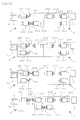
- FIG. 1 is a schematic view for explaining the configuration of one example of the work machining apparatus to which the control program of the invention is applied.
- the work machining apparatus of this embodiment is a tri-axial NC lathe (hereinafter referred to as an NC lathe) 1 having three main spindles 111, 112 and 113.
- the NC lathe 1 has a first headstock 101 which can move back and forth in the Z direction and a cylindrical first main spindle 111 as a first main spindle which is rotatably supported by this first headstock 101, a third headstock 103 which is arranged in parallel with the first headstock 101 and can move back and forth in the Z direction and a third main spindle 113 as a third main spindle which is rotatably supported by this third headstock 103, and a second headstock 102 which is arranged opposing to the first headstock 101 and can move back and forth in the Z direction between a position opposing to the first headstock 101 and a position opposing to the third headstock 103 and a second main spindle 112 as a second main spindle which is rotatably supported by this second headstock 102.
- the work W which has been machined is discharged outside by means of a work transfer apparatus 5 such as a loader.
- the NC lathe 1 at least three tool rests are provided respectively corresponding to the first main spindle 111, the second main spindle 112 and the third main spindle 113. By using tools mounted on these three tool rests, machining of the work W held by the chuck of the first main spindle 111, the second main spindle 112 and the third main spindle 113 can be performed simultaneously.
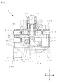
- FIG. 2 is a view for explaining the specific configuration of the above-mentioned NC lathe 1, which is a front view of the NC lathe.
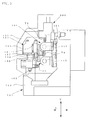
- FIG. 3 is a side view of the NC lathe 1 shown in FIG. 2 .
- the three headstocks 101, 102 and 103 are provided such that they can freely move back and forth in the Z direction on a ZY surface 121 of a bed 120 which is formed in an approximate inverted L shape, as viewed from the side.
- three sets of guiderails 131, 132 and 133 are laid in the Z direction.
- the first headstock 101 is provided in a saddle 134 which moves back and forth in the Z direction by the guidance of the guiderail 131
- the second headstock 102 is provided in a saddle 135 which moves back and forth in the Z direction by the guidance of the guiderail 132
- the third headstock 103 is provided in a saddle 136 which moves back and forth in the Z direction by the guidance of the saddle 136 which moves back and forth in the Z direction by the guidance of the guiderail 133.
- the saddle 135 is formed in a rectangular shape as viewed from the front, having the longer side thereof in the Y direction.
- a guiderail 137 is laid on the surface thereof in the Y direction.
- the second headstock 102 can move freely back and forth also in the Y direction by the guidance of the guiderail 137.
- the guiderail 133 which guides the movement in the Z direction of the third headstock 103 extends to the other end (upper right end in FIG. 2 ) of the ZY surface 121 and can move the work W held by the chuck at the front end of the third main spindle 113 to a position where the work can be delivered to the adjacent work transfer apparatus 5.
- care must be taken so that interference of the third headstock 103 and the saddle 136 with the saddle 136 of the second headstock 102 can be avoided.
- FIG. 4 is a view showing one example of a configuration for avoiding the above-mentioned interference.
- the saddle 136 on which the third headstock 103 is mounted a concave part 136a is formed to avoid the interference with the saddle 135 of the second headstock 102.
- the work transfer apparatus 5 such as a loader
- the saddle 135 and the guiderail 137 enter the inside of the concave part 136a, whereby the interference of the saddle 136 and the saddle 135 can be prevented.
- a portal tool rest support 138 is provided from the front middle of a base 122 of the bed 120 to the upper middle of the ZY surface 121.
- This tool rest support 138 is provided with a first tool rest 150 having a plurality of tools T1 for machining the work W held by the chuck of the first main spindle 111, a second tool rest 160 having a plurality of tools T2 for machining the work W held by the chuck of the second main spindle 112 and a third tool rest 170 having a plurality of tools T3 for machining the work W held by the chuck of the third main spindle 113.
- the first tool rest 150 is provided above the tool rest support 138 facing the first headstock 101, and has a guide 151 laid in the X direction, a saddle 152 which moves back and forth in the X direction by the guidance of this guide 151, a guiderail 153 which is laid in the Y direction on one surface of the saddle 152 and a tool rest body 154 which moves back and forth in the Y direction by the guidance of this guiderail 153.
- the plurality of tools T1 are mounted in a tool mounting part 155 of the tool rest body 154 in such a manner that they are arranged like teeth in a comb.
- a predetermined tool T1 is allocated to the machining position by the move of the saddle 152 in the X direction. Machining of the work W by the tool T1 is performed by the move of the tool rest body 154 in the Y direction and the move of the first headstock 101 in the Z direction.
- the second tool rest 160 is provided above the tool rest support 138 facing the second headstock 102, and has a guide 161 laid in the X direction, a saddle 162 which moves back and forth in the X direction by the guidance of this guide 161, a guiderail 163 which is laid in the Y direction on one surface of the saddle 162 and a tool rest body 164 which moves back and forth in the Y direction by the guidance of this guiderail 163.
- the plurality of tools T2 are mounted in a tool mounting part 165 of the tool rest body 164 in such a manner that they are arranged like teeth in a comb.
- a predetermined tool T2 is allocated to the machining position by the move of the saddle 162 in the X direction. Machining of the work W by the tool T2 is performed by the move of the tool rest body 164 in the Y direction and the move of the second headstock 102 in the Z direction.
- the third tool rest 170 is provided under the tool rest support 138 facing the third headstock 103, and has a guide 171 laid in the Y direction, a saddle 172 which moves back and forth in the Y direction by the guidance of this guide 171, a guiderail 173 which is laid in the Y direction on one surface of the saddle 172 and a tool rest body 174 which moves back and forth in the Y direction by the guidance of this guiderail 173.
- the plurality of tools T3 are mounted in a tool mounting part 175 of the tool rest body 174 in such a manner that they are arranged like teeth in a comb.
- a predetermined tool T3 is allocated to the machining position by the move of the saddle 172 in the X direction. Machining of the work W by the tool T3 is performed by the move of the tool rest body 174 in the Y direction and the move of the third headstock 103 in the Z direction.
- a fourth tool rest 180 is provided to machine the work W held by the chuck of the second main spindle 112 or the third main spindle 113.
- this fourth tool rest 180 in a tool installation part 187 of a tool rest body 186 which can move freely back and forth in three axial directions of X, Y and Z by an X-direction guiderail 181, a Y-direction guiderail 182 and a Z-direction guiderail 183, a plurality of tools T4 are arranged in the X direction. Due to the move of the tool rest body 186 in the X direction, the tool T4 is allocated to the machining position. Machining of the work W by the tool T4 is performed by the move of the second headstock 102 or the third headstock 103 in the Z direction and the move of the tool rest body 186 in the Y direction.
- machining of the work W can be performed by the tool T4 simultaneously with machining by the tool T2 or the tool T3, without the fear of interference of the tool T4 with other tools (tool T2 or tool T3) of other tool rests (second tool rest 160 or third tool rest 170).
- tools T1 to T4 in addition to cutting tools such as tool bites, rotary tools such as drills and taps can also be used.
- the base 122 of the bed 120 is provided with, at the front and the back thereof, an inclined surface 123 for collecting cut scraps and coolants formed and used in machining the work W by means of the tools T1 to T4.
- the cut scraps and coolants which have been collected by this inclined surface 123 and 123 are collected in a collecting tank 124 which is withdrawably provided in the base 122.
- the configuration of the NC lathe is not limited to that mentioned above.
- FIGs. 5 and 6 another embodiment of an NC lathe to which the control program of the invention can be applied will be explained hereinbelow.
- the same parts and members are explained by the same reference numerals, and a detailed explanation thereof is omitted.
- another tri-axial NC lathe provided adjacently to the NC lathe 1, since it has the same configuration as that of the NC lathe 1 except for the arrangement of each constituting members which is line symmetrical with that of the NC lathe 1, and hence, a detailed explanation is omitted.
- a guiderail 140 is laid in the Z direction.
- the third headstock 103 is provided on a saddle 141 which moves back and forth in the Z direction by the guidance of the guiderail 140.
- This configuration has an advantage that the provision of the concave part 136(a) in the saddle 141 (see FIG. 4 ) to avoid the interference of the third headstock 103 with the saddle 137 and the second headstock 102 is not necessary unlike the above-mentioned embodiment.
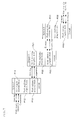
- the control system of the first main spindle 111 (hereinafter referred to as the "system 1") has a work supply program block P11 for supplying the work W from the bar feeder 2 to the first main spindle 111, a work machining program block P12 for machining the work W by the relative movement of the tool T1 mounted on the first tool rest 150 with the first main spindle 111, and a work delivery block program P13 for delivering the work W which has machined by the tool T1 to the second main spindle 112.
- the work supply program block P11, the work machining program block P12 and the work delivery program block P13 each consists of an independent program. On the condition that the program of the work supply program block P11 ends, the program of the work machining program block P12 starts. On the condition that the program of the work machining program block P12 ends, the program of the work delivery program block P13 starts.
- the work supply program block P11 is linked with the work supply program in the bar feeder 2 (see FIG. 1 ), and work receiving action of the first main spindle 111 starts after waiting (queuing) until the bar feeder 2 is prepared for delivering a work (cooperation).
- the control system of the second main spindle 112 (hereinafter referred to as "system 2") has a work receiving program block P21 for receiving the work W from the first main spindle 111 and held by the chuck at its end, a work machining program block P22 for machining the work W by the relative movement of the tool T2 mounted on the second tool rest 160 and/or the tool T4 mounted on the third tool rest 180 with the second main spindle 112, and a work delivery block program P23 for delivering the work W which has been machined by the tool T2 and/or the tool T4 to the second main spindle 112.
- system 2 has a work receiving program block P21 for receiving the work W from the first main spindle 111 and held by the chuck at its end, a work machining program block P22 for machining the work W by the relative movement of the tool T2 mounted on the second tool rest 160 and/or the tool T4 mounted on the third tool rest 180 with the second main spindle 112, and a work delivery block program P23 for
- the program of each of the work supply program block P21, the work machining program block P22 and the work delivery program block P23 is an independent program. On the condition that the program of the work supply program block P21 ends, the program of the work machining program block P22 starts. On the condition that the program of the work machining program block P22 ends, the program of the work machining program block P23 starts.
- the work W is received from the first main spindle 111, the work W which has been received is machined, and the work W which has been machined is then delivered to the third main spindle 113.
- the work receiving program block P21 is linked with the work delivery program P13 in the system 1, and the work receiving action of the second main spindle 112 starts after waiting (queuing) until the first main spindle 111 is prepared for delivering a work (cooperation).
- the control system of the third main spindle 113 (hereinafter referred to as the "system 3") has a work supply program block P31 for receiving the work W from the second main spindle 112 and holding it by the chuck at its end, a work machining program block P32 for machining the work W by the relative movement of the tool T3 mounted on the third tool rest 170 and/or the tool T4 mounted on the fourth tool rest 180 with the third main spindle 113, and a work delivery block program P33 for discharging the work W which has been machined by the tool T3 and/or the tool T4 outside the apparatus.
- the program of each of the work receiving program block P31, the work machining program block P32 and the work delivery program block P33 is an independent program. On the condition that the program of the work receiving program block P31 ends, the program of the work machining program block P32 starts. On the condition that the program of the work machining program block P32 ends, the program of the work delivery program block P33 starts.
- the work W is received from the second main spindle 112, the work W which has been received is machined, and the work W which has been machined is then delivered to a work transfer apparatus 5 such as a loader.
- the work receiving program block P31 is linked with the work delivery program P23 in the system 2, and the work receiving action of the third main spindle 113 is started after waiting (queuing) until the second main spindle 112 is prepared for receiving the work (cooperation).
- the work delivery program block P33 is linked with the work delivery program in the work transfer apparatus 5 (see FIG. 1 ), and the work receiving action of the third main spindle 113 starts after waiting (queuing) until the work transfer by the work transfer apparatus 5 is prepared for receiving a work (cooperation).
- the rewinding program is provided such that a cue of the head of the program in each system can be performed.
- a command for rewinding M02 or the like can be given.
- FIG. 8 whenever receiving, machining and discharging of a work W are completed, a cue of the head of the program is performed by rewinding, whereby execution of the program is repeated for each work W.
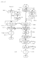
- FIGs. 9 and 10 each show a flow chart for explaining the operation procedures by the above-mentioned control program.
- FIGs. 12 to 15 are views showing the operation of the work processing system in each step of this flow chart.
- the above-mentioned control program is installed in a single control device provided in the NC lathe.
- the above-mentioned control device executes the control program which has been installed, and issues various control commands for transfer of the headstocks, rotation of the main spindles, transfer of the tool rests, or the like.
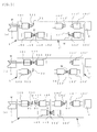
- the following explanation is made taking as an example the work machining system shown in FIG. 11 in which two NC lathes are provided side by side. This work processing system is formed of the above-mentioned NC lathe 1 and the other NC lathe 1'.
- the first headstock 101, the second headstock 102, the third headstock 103 or the like are arranged line symmetrically with the first headstock, the second headstock, the third headstock or the like of the above-mentioned NC lathe 1 with respect to the Y axis [indicated by putting (') marks on each part].
- the work W is machined in the order of (i) and (ii) (see FIG. 11 ). Thereafter, as shown by (iii), the work W is delivered from the third main spindle 113 to the third main spindle 113' of the other lathe 1' (shown on the right of the figure). In the other lathe 1', the work W is machined while being delivered in the order of (iv) and (v) from the third main spindle 113' to the second main spindle 112' and the first main spindle 111'.
- the work W which has been machined is discharged outside by means of a work transfer apparatus 3 such as a loader.
- a work transfer apparatus 3 such as a loader.
- the third main spindle 113' constitutes the "first main spindle”
- the second main spindle 112' constitutes the "second main spindle”
- the first main spindle 111' constitutes the "third main spindle”.
- the third main spindle 113 of the NC lathe 1 functions as the work supply apparatus in the other NC lathe 1'.
- the third main spindle 113' of the other NC lathe 1' functions as the work discharge apparatus of the third main spindle 113 of the NC lathe 1.
- the work supply program is executed (Step S100). Due to the execution of this program, a bar-like work W is sent from the bar feeder 2 to the through-hole of the first main spindle 111.
- the tool rest body 154 of the first tool rest 150 moves in the X direction, and the tool T1 for positioning is allocated to the machining position. Then, the tool T1 for positioning is positioned at a predetermined position in front of the first main spindle 111.
- the bar-like work W which has been sent from the bar feeder 2 via the through hole of the first main spindle 111 is projected from the front end of the first main spindle 111 and is abutted with the tool T1 for positioning, whereby positioning is performed.
- the chuck provided at the front end of the first main spindle 111 is closed to hold the work W, whereby the work supply program is completed.
- Step S101 the work machining program is executed (Step S101). Due to the execution of this program, as shown in FIG. 12(b) , the tool T1 for machining the work W is allocated to the machining position. Machining of the work W is performed by the movement of this tool T1 in the Y direction and the movement of the first main spindle 111 in the Z direction. After the completion of the machining of the work W by the tool T1 (Step S102), the work machining program ends, and the work delivery program is then executed. Due to the execution of this program, whether the system 2 has started or not yet is judged (Step S103). If the system 2 has not started yet, the program temporarily stops, and remains in the stand-by state until the system 2 starts (Steps S104 and S105).
- Step S106 If the system 2 has started, according to the command of the work delivery program, queuing with the system 2 is performed (Step S106). After completion of the queuing (after preparation for work receiving is completed), the first headstock 101 is allowed to move, together with the second headstock 102, in the direction in which they get closer to each other, in the common Z-axis direction. As shown in FIG. 12(c) , at a position which is almost halway between the headstock 101 and the headstock 102, the work W is delivered from the first main spindle 111 to the second main spindle 112 (Step S107). The first headstock 101 returns to its initial position where a work W for a next machining is received from the bar feeder 2.
- Step S108 the program judges whether or not machining of a predetermined number of work W is completed. If completed, the program ends. If not completed, as shown in FIG. 12(d) , the program returns to the Step S100 to execute the work supply program. As shown in FIG. 12(d) , a work W to be machined next, which has been supplied from the bar feeder 2, is received. Thereafter, the procedure and operation of the Step S101 and subsequent steps are repeated.
- Step S200 the work receiving program is executed, and judgment is performed to examine whether the system 1, with which transfer of the work W is conducted, has started normally.
- the system 1 When the system 1 has not started normally, for example, due to occurrence of an abnormality such as breakage of tools, unsuccessful work supply and erroneous program execution, the system 2 temporarily stops and remains in the standby state until the system 1 is recovered to its normal start-up state (Steps S201 and S202). If the system 1 has started normally, queuing is performed until the first main spindle 111 is prepared for delivering a work W (Step S203). After completion of the queuing, as shown in FIG.
- the second headstock 102 is allowed to move in the direction in which the second headstock 102 gets closer to the first headstock 101.
- the work W is received from the first main spindle 111 to the second main spindle 112 (Step S204).
- the cut-off tool T2 on the second tool rest 160 is allocated to the machining position. Then, while allowing the second main spindle 112 to be rotated in the same direction at a speed synchronized with the rotational speed of the first main spindle 111, cutting off of the work W is performed by means of the cut-off tool T2.
- the work which has been machined at the first main spindle 111 is separated from a bar material.
- Step S205 the work machining program is executed (Step S205).
- the control programs of the system 1, the system 2 and the system 3 are independent from each other, even if an abnormality such as breakage of tools, unsuccessful work supply and erroneous program execution occur in the system 1 or the system 3 after the work W is delivered from the first main spindle 111 to the second main spindle 112, for example, the operations of the Step S205 and the subsequent steps in the system 2 are executed.
- Step S206 the work delivery program is executed, and whether the system 3 has started normally or not yet is judged first (Step S207). If the system 3 has not started normally due to occurrence of an abnormality or the like, the system 2 temporarily stops and remains in the stand-by mode until the system 3 is recovered to its normal start-up state (Steps S208 and S209).
- Step S210 queuing is performed until the third main spindle 113 is prepared for receiving a work.
- the second headstock 102 is moved in the Y direction and the Z direction, i.e. in a direction in which the second headstock 102 gets closer to the third headstock 103 in the common Z direction.
- the work W is delivered from the second main spindle 112 to the third main spindle 113 (Step S211).
- the control programs of the system 1, the system 2 and the system 3 are independent from each other, even if an abnormality or the like occurs in either or both of the system 3 and the system 1 after the work W is delivered from the second main spindle 112 to the third main spindle 113, the operations of the Step S211 and subsequent steps in the system 2 are executed. Specifically, after the work W is delivered from the second main spindle 112 to the third main spindle 113 in the Step S211, the second headstock 102 returns to its initial position as shown in FIG. 13(b) . Then, the program judges whether the machining of a predetermined number of works W is completed or not (Step S212). If completed, the work delivery program ends.
- Step S203 the program returns to the step S200 to execute the work receiving program, and queuing with the first main spindle 111 is performed.
- Step S204 the work W is received from the first main spindle 111 (Step S204). Thereafter, the procedure and operation of the Step S205 and subsequent steps are repeated.
- Step S300 the work receiving program is executed, and judgment is performed to examine whether the system 2, with which transfer of the work W is conducted, has started normally (Step S300).
- the system 2 has started normally, due to occurrence of an abnormality, for example, the system 3 temporarily stops and remains in the standby state until the system 2 recovers to its normal start-up state (Steps S301 and S302). If the system 2 has started normally, queuing is performed until the second main spindle 112 is prepared for delivering a work W (Step S303).
- the second main spindle is prepared for delivering, as shown in FIG.
- the second headstock 102 is allowed to move in the direction in which the second headstock 102 gets closer to the third headstock 103 in the Z axis direction.
- the work W is received from the second main spindle 112 to the third main spindle 113 (Step S304), and the second headstock 102 returns to its initial position for machining the work W.
- the control programs of the system 1, the system 2 and the system 3 are independent from each other, even if an abnormality or the like occurs in either or both of the system 1 and the system 2 after the work W is delivered from the second main spindle 112 to the third main spindle 113 in the Step S304, the operations of the Step S305 and subsequent steps in the system 3 are executed.
- Step S305 The delivery of the work W from the second main spindle 112 to the third main spindle 113 is completed by the above-mentioned operations.
- the work machining program is executed (Step S305). Due to the execution of this program, the tool T3 and/or the tool T4 for machining the work W are allocated to the machining position, and as shown in FIG. 13(b) and FIG.13(c) , machining of the work W is performed by the movement of the tool T3 and/or the tool T4 in the Y direction and the movement of the third main spindle 113 in the Z direction.
- Step S306 After completion of machining of the work W by the tool T3 and/or the tool T4 (Step S306), the work discharge program is executed and queuing with the third main spindle 113' of the other NC lathe 1' is performed (Step S307). After completion of the queuing, as shown in FIG. 13(d) , the third main spindle 103 is moved in the direction in which the third main spindle 103 gets closer to the third main spindle 113' of the other NC lathe 1' in the Z axis direction, and the work W is delivered from the third main spindle 113 to the third main spindle 113' of the other NC lathe 1' (Step S308).
- the third headstock 103 After completion of the delivery of the work W, the third headstock 103 returns to its initial position for machining the work W. Then, judgment is performed to examine whether machining of a predetermined number of work W is completed (Step 309). If completed, the program ends. If not completed, the program returns to the Step S300 to execute the work receiving program, and queuing with the second main spindle 112 is performed (Step S303). As shown in FIG. 14(a) , the work W is received from the second main spindle 112 (Step S304). Thereafter, the procedure and operation of the Step S304 and subsequent steps are repeated.
- the same procedure and operation as mentioned above are repeated.
- the work W is delivered in the order of the third main spindle 113' , the second main spindle 112' and the first main spindle 111'.
- the third main spindle 113' the work W is received from the third main spindle 113 of the NC lathe 1. Then, after the third main spindle 113' returns to its initial position for machining the work W, the third main spindle 113'performs the operations shown in FIGs. 14(a), (b) and (c) while following the same steps of the Step S101 and subsequent steps in the flow chart in FIG. 9 .
- the second main spindle 112' performs the operations shown in FIGs. 14(b), (c) and FIG. 15(a) while following the same steps of the Step S200 and subsequent steps in the flow chart in FIGs. 9 and 10 .
- the first main spindle 111' performs the operations shown in FIGs. 15(a), (b) and (c) while following the same steps of the Step S300 and subsequent steps in the flow chart in FIG. 10 .
- the queuing in the Step S307 the queuing is performed with a loader for work discharge after completion of machining, and the work W is delivered from the first main spindle 111' to a loader in the Step S308.
- Step S201 judges whether there is an abnormality in the system 1, if an abnormality occurs in the system 1, the system 2 temporarily stops (Step S201), or work delivery from the first main spindle 111 to the second main spindle 112 is disabled in the queuing steps S106 or S203, the second main spindle 112 temporarily stops in this step.
- program blocks are provided. By these program blocks, if an abnormality occurs in a system positioned on the upstream of each system, the operation temporarily stops before the start or after the completion of machining of the work, whereby elimination of the abnormality can be waited.
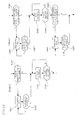
- the flow chart shown in FIG. 16 is basically the same as the flow charts shown in FIG. 9 and FIG. 10 . Therefore, only additional steps are shown, and other steps are not shown and a detailed explanation thereof is also omitted. As shown in FIG.
- Step S401 which judges whether an abnormality occurs in the system 1
- Step S402 which issues a command to temporarily stop the program execution if occurrence of an abnormality is confirmed in the Step S401
- Step S403 which retains this temporal suspension state until an abnormality in the system 1 is eliminated.
- Step S405 which judges whether an abnormality occurs in the system 1 or the system 2
- Step S406 which issues a command to temporarily stop the program execution if occurrence of an abnormality is confirmed in this step S405
- Step S407 which retains this temporal suspension state until an abnormality in the system 1 or the system 2 is eliminated.
- a program block (Steps S401, S402, S403 and Steps S405, S406 and S406) to temporarily stop the execution of the program when an abnormality occurs in upstream systems is provided before the Step S205 in the system 2, before the Step S305 in the system 3 and before the Step S306 in the system 3.
- the reason therefor is as follows.
- the NC lathe 1 in this embodiment is set such that machining time of the work W is longer in upstream steps. If an abnormality occurs in upstream steps, downstream steps are caused to stop temporarily in a sequential manner, whereby downstream steps can stop temporarily in a timely manner, and the stand-by time in downstream steps during the elimination of the abnormality can be shortened as much as possible.
- this program block be provided such that execution of the program in each system 1, 2 and 3 can temporarily stop in the most timely manner if an abnormality occurs in each of the systems 1, 2 and 3 and that execution of the program of each system 1, 2 and 3 can be started again in the least wasteful state. Therefore, it is preferred that this program block be provided either before the Step S205 or after the Step S206 or both before the Step S205 and after the Step S206, and either before the Step S305 or after the Step 306 or both before the Step S305 and after the Step 306, taking into consideration comprehensively the machining time of the work W, the supply time of the work W, the discharge time of the work W or the like.
- a step may be provided to temporarily stop the execution of the program due to an abnormality of the bar feeder 2 which is a work supply apparatus arranged in upstream steps.
- the preferred embodiments of the invention are explained hereinabove, which are in no way intended to limit the invention.
- the above explanation was made taking as an example the rewind command of an M02 code, which is commonly used in an NC machining apparatus. It is needless to say other codes can be used.
- the number of works is counted, whether a work to be machined is the last work or not is judged in each program, and the programs end in a sequential manner when the last work is machined.
- the system may be configured such that the program remains in the stand-by state until the work which has been machined at the third main spindle is delivered to a work transfer apparatus and all programs end after completion of this delivery.
- the number of the NC lathe constituting the above-mentioned work machining system is not limited to two.
- the control program of the invention can be applied if the number of the NC lathe is three or more.
- execution of a program in downstream systems temporarily stops.
- the invention can be applied to a multi-axial work machining apparatus in which a plurality of machining is conducted sequentially for a single work.
- a machining apparatus such as an NC lathe
- the invention can also be widely applied to a variety of apparatuses including an assembling machine in which a number of components are assembled to a semi-finished product to obtain a finished product.
Landscapes
- Engineering & Computer Science (AREA)
- Mechanical Engineering (AREA)
- Human Computer Interaction (AREA)
- Manufacturing & Machinery (AREA)
- Physics & Mathematics (AREA)
- General Physics & Mathematics (AREA)
- Automation & Control Theory (AREA)
- Numerical Control (AREA)
- Turning (AREA)
- Management, Administration, Business Operations System, And Electronic Commerce (AREA)
Abstract
Description
- The invention relates to a control program to be incorporated in a control device for a work machining apparatus such as an NC lathe, as well as to a control device for a work machining apparatus for executing the control program.
- If a work is machined by a plurality of steps, by using a work machining apparatus such as a machining tool provided with a plurality of main spindles and tool rests, the work is machined in a sequential manner while being transferred between the main spindles.
- For example,
Patent Document 1 discloses a work machining apparatus in which two opposing headstocks 24 and 26 which are movable in the X direction are provided, and an unmachined work 46, which is held by rotatable main spindles 28 and 30 respectively provided on the headstocks 24 and 26, is machined by tools 36 and 38 which are mounted on turret tool rests 32 and 34 provided corresponding to the headstocks 24 and 26.
In addition, by the movement in the Z direction, the two headstocks 24 and 26 are made get closer to each other, and the work is delivered from one of the main spindles (the main spindle 28) to the other main spindle 30. - As for the supply of the unmachined work 46 , the unmachined work 46 is directly supplied to the main spindle 28 from a work stocker 44 provided at one end of a
bed 10. Discharge of themachined work 52 from the main spindle 30 is performed by a work discharge apparatus 50 provided at one end of thebed 10 such that it opposes to the work stocker 44.
Patent Document 1:DE-A-4310038 (see the drawings) - However, in the case of a work machining apparatus similar to that mentioned above, which is provided with a plurality of main spindles and a plurality of tool rests which machines a work while transferring the work between the main spindles, the NC program becomes a multi-system program corresponding to the number of the main spindle, and control of the main spindle and the corresponding tool rest is performed in each system. In this case, normally, the NC programs in these systems are started simultaneously and rewound simultaneously when machining is completed.
- Such a control method has the following problem. Specifically, a series of machining programs is prepared for each system, and supply, machining and discharge of a work are controlled by this machining program. Therefore, when machining of the first work is initiated by starting the work machining apparatus, since the second and subsequent main spindles move for machining in spite of the absence of a work to be machined, air cut is caused, resulting in wasteful consumption of power or the like. Such a problem occurs also at the time of the completion of machining of the last work.
This problem can be eliminated by, for example, creating a subprogram by which the number of works to be machined is counted and, based on the counted number of works, a stand-by command is issued to predetermined main spindles in order to avoid air cut. However, preparation of such an exclusive subprogram in addition to the original machining program makes creation of an entire machining program troublesome. - The invention has been made in view of the above-mentioned problem, and the object thereof is to provide a control program which can eliminate a wasteful movement such as air cut when a work is machined by using a multi-spindle NC lathe or the like, and can perform supply and discharge of a work without an exclusive program, as well as to provide a control device for a work machining apparatus which executes this control program.
- In order to solve the above-mentioned problem, the control program of the invention is a control program for controlling a work machining apparatus provided with a plurality of work fixing parts, and performs machining of a work which has been fixed to the work fixing part in a work machining part provided corresponding to the work fixing part while transferring the work between these work fixing parts, wherein
a control system is provided for each pair of the work fixing part and the work machining part,
each control system has a work receiving program block which controls the movement of a movable body comprising the working fixing part and the work machining part when an unmachined work is received, a work machining program block which controls the movement of a movable body comprising the work fixing part and the work machining part when a work which has been fixed to the work fixing part is machined in the work machining part, and a work discharge program block which controls the movement of a movable body comprising the work fixing part and the work machining part when the work which has been machined is discharged,
the work machining program block starts on the condition that the work receiving program block ends and the work discharge block program starts on the condition that the work machining program block ends,
the work receiving program block is associated with the work supply program of the work supply apparatus, or the work discharge program block is associated with a work transfer program of a work transfer apparatus so that a command is issued to the work receiving program block or the work discharge program block to perform queuing and cooperation operations which are necessary when transferring a work between the work supply apparatus or the work transfer apparatus, and
a command to perform a cue of the head of the program of each control system is issued at the last part of the control system. In this case, it is preferred that, in the work receiving program block, the work machining program block and the work discharge program block, a command be provided so that execution of the program ends when the number of machined works reaches a predetermined number. - According to this control program, machining of a work is not performed until supply of a work is completed, whereby air cut caused by idle machining can be prevented. In addition, at the time of work supply, wasteful air cut can be prevented since the control program remains in the standby state until the work supply part is prepared to supply.
Furthermore, at the time of discharging a work, a work is not discharged until machining of a work is completed, and the control program remains in the standby state until the work discharge part is prepared to discharge, whereby wasteful air cut can be prevented.
In addition, since receiving and discharge of a work can be performed without using an exclusive program, the configuration of the control program can be simplified and the creation of the program can be facilitated. - The control program of the invention can be used when a plurality of similar work machining apparatuses are combined to form a work machining system.
In this case, the work supply program of the work supply apparatus is the work discharge program block of the work fixing part and the work machining part which perform the last machining in the work machining apparatus provided in an upstream step, and the work transfer program of the work transfer apparatus is the work receiving program block of the work fixing part and the work machining part which perform the first machining in the work machining apparatus provided in a downstream step.
The work machining apparatus may be a machining tool or various assembling machines insofar as it performs machining (including assembling) of a work. For example, the work machining apparatus may be an NC lathe. Specifically, it may be a tri-axial NC lathe in which the work fixing part comprises a first main spindle which receives an unmachined work from the work supplying apparatus, a third main spindle which is arranged in parallel with the first main spindle such that it faces the same direction as the first main spindle and a second main spindle which is arranged opposing to the first main spindle, is allowed to move freely back and forth between a position on the axial line of the first main spindle and a position on the axial line of the third main spindle, and receives a work from the first main spindle and transfers the work to the third main spindle by the back-and-forth movement along the axial line of the first main spindle or the axial line of the third main spindle, and the work machining part comprises a first tool rest provided corresponding to the first main spindle, a second tool rest provided corresponding to the second main spindle and a third tool rest provided corresponding to the third main spindle.
In an NC lathe with such a configuration, machining is performed while a work is directly transferred from one main spindle to another main spindle in the order of the first main spindle to the second main spindle and then to the third main spindle.
If a plurality of work machining apparatuses are connected or a plurality of work fixing parts and a plurality of work machining parts are provided in a single work machining apparatus, a plurality of control systems are provided corresponding to each pair of a work fixing part and a work machining part. Since the plurality of control systems are independent from each other, during the execution of a program in one control system, if an abnormality such as tool breakage, erroneous work supply and erroneous program execution occurs in other control systems, the program is executed in the above-mentioned one control system, whereby supply, machining or discharge of a work are performed.
When the above-mentioned one control system cooperating with the above-mentioned other control systems which encounters an abnormality, execution of the program in the above-mentioned one control system temporarily stops for the first time. An operator who notices the abnormality can manually stop execution of a program in the above-mentioned one control system. However, if execution of a program is forced to stop during machining of a work, the work may get a scratch, resulting in formation of defective products.
Therefore, in the invention, a program block may be provided in at least one of the plurality of control systems which are independent from each other. The program block judges whether there is any abnormality in the other control systems, and if any abnormality is judged to exist, it temporarily stops initiation of work machining or temporarily stops execution of the program of the control system after work machining is completed.
By providing such a program block, if an abnormality occurs in the above-mentioned other control systems, execution of the program stops before the start of work machining or immediately after completion of work machining in the above-mentioned one control system, and an operator may be urged to eliminate the abnormality in the above-mentioned other control systems.
Control of each movable body of the work machining apparatus can be performed by means of a control device in which the above-mentioned control program is installed, which issues, by executing the installed control program, a command to control movement of the above-mentioned movable body comprising the work fixing part and the work machining part. - Since the control program of the invention has the above-mentioned configuration, it is free of wasteful motions such as air cut, and does not require another exclusive program for the supply and discharge of a work.
Therefore, it is possible to obtain a control program and a control device for a work machining apparatus which can save both energy and cost. -
-
FIG. 1 is a schematic view for explaining the configuration of one example of an NC lathe as the work machining apparatus to which the control program of the invention is applied; -
FIG. 2 is a front view of the NC lathe shown inFIG. 1 for explaining in more detail the structure of the NC lathe shown inFIG. 1 ; -
FIG. 3 is a right side view of the NC lathe shown inFIG. 2 ; -
FIG. 4 is a view showing one example of a configuration for preventing interference of the third headstock and the saddle thereof with the saddle on the second headstock; -
FIG. 5 is a front view of another embodiment of the tri-axial NC lathe constituting the work machining system; -
FIG. 6 is a right front view of the NC lathe shown inFIG. 5 ; -
FIG. 7 is a block view showing the configuration of one example of the control program of the invention; -
FIG. 8 is a schematic view showing a flow of the control program when a plurality of works are machined; -
FIG. 9 is a flow chart for explaining the operation procedure by the control program; -
FIG. 10 is a flow chart for explaining the operation procedure by the control program; -
FIG. 11 is a schematic view showing the work machining system formed by combining two NC lathes; -
FIG. 12 is a view showing the action of the work machining system in each step of the flow charts shown inFIG. 9 andFIG. 10 ; -
FIG. 13 is a view showing the action of the work machining system in each step of the flow charts shown inFIG. 9 andFIG. 10 ; -
FIG. 14 is a view showing the action of the work machining system in each step of the flow charts shown inFIGs. 9 and10 ; -
FIG. 15 is a view showing the action of the work machining system in each step of the flow charts shown inFIGs. 9 and10 ; and -
FIG. 16 is an extract of the main part of the flow chart according to another embodiment of the operation procedure by the control program. - A preferred embodiment of the invention will be described below in detail with reference to the drawings.
-
FIG. 1 is a schematic view for explaining the configuration of one example of the work machining apparatus to which the control program of the invention is applied.
The work machining apparatus of this embodiment is a tri-axial NC lathe (hereinafter referred to as an NC lathe) 1 having threemain spindles
TheNC lathe 1 has afirst headstock 101 which can move back and forth in the Z direction and a cylindrical firstmain spindle 111 as a first main spindle which is rotatably supported by thisfirst headstock 101, athird headstock 103 which is arranged in parallel with thefirst headstock 101 and can move back and forth in the Z direction and a thirdmain spindle 113 as a third main spindle which is rotatably supported by thisthird headstock 103, and asecond headstock 102 which is arranged opposing to thefirst headstock 101 and can move back and forth in the Z direction between a position opposing to thefirst headstock 101 and a position opposing to thethird headstock 103 and a secondmain spindle 112 as a second main spindle which is rotatably supported by thissecond headstock 102. - In this
NC lathe 1, as shown by numerals (i), (ii) and (iii) in the figure, a work W which has been supplied from abar feeder 2, which is a work supply apparatus, is machined, with the work being sequentially transferred from the firstmain spindle 111, the secondmain spindle 112 and the thirdmain spindle 113. The work W which has been machined is discharged outside by means of awork transfer apparatus 5 such as a loader. - Although not shown in
FIG. 1 , in theNC lathe 1, at least three tool rests are provided respectively corresponding to the firstmain spindle 111, the secondmain spindle 112 and the thirdmain spindle 113. By using tools mounted on these three tool rests, machining of the work W held by the chuck of the firstmain spindle 111, the secondmain spindle 112 and the thirdmain spindle 113 can be performed simultaneously. -
FIG. 2 is a view for explaining the specific configuration of the above-mentionedNC lathe 1, which is a front view of the NC lathe.FIG. 3 is a side view of theNC lathe 1 shown inFIG. 2 .
The threeheadstocks ZY surface 121 of abed 120 which is formed in an approximate inverted L shape, as viewed from the side. Specifically, on theZY surface 121, three sets ofguiderails 131, 132 and 133 are laid in the Z direction. Thefirst headstock 101 is provided in a saddle 134 which moves back and forth in the Z direction by the guidance of the guiderail 131, thesecond headstock 102 is provided in asaddle 135 which moves back and forth in the Z direction by the guidance of theguiderail 132 and thethird headstock 103 is provided in asaddle 136 which moves back and forth in the Z direction by the guidance of thesaddle 136 which moves back and forth in the Z direction by the guidance of the guiderail 133.
Thesaddle 135 is formed in a rectangular shape as viewed from the front, having the longer side thereof in the Y direction. Aguiderail 137 is laid on the surface thereof in the Y direction.
Thesecond headstock 102 can move freely back and forth also in the Y direction by the guidance of theguiderail 137. - The guiderail 133 which guides the movement in the Z direction of the
third headstock 103 extends to the other end (upper right end inFIG. 2 ) of theZY surface 121 and can move the work W held by the chuck at the front end of the thirdmain spindle 113 to a position where the work can be delivered to the adjacentwork transfer apparatus 5.
During the move of thethird headstock 103 to the other end, care must be taken so that interference of thethird headstock 103 and thesaddle 136 with thesaddle 136 of thesecond headstock 102 can be avoided. -
FIG. 4 is a view showing one example of a configuration for avoiding the above-mentioned interference.
As shown inFIG. 4(a) , thesaddle 136 on which thethird headstock 103 is mounted, a concave part 136a is formed to avoid the interference with thesaddle 135 of thesecond headstock 102.
When thethird headstock 103 moves to the other end of theZY surface 121 where the work W is delivered from the thirdmain spindle 113 of theNC lathe 1 to thework transfer apparatus 5 such as a loader, as shown inFIG. 4(b) , thesaddle 135 and theguiderail 137 enter the inside of the concave part 136a, whereby the interference of thesaddle 136 and thesaddle 135 can be prevented. - As shown in
FIGs. 2 and3 , from the front middle of abase 122 of thebed 120 to the upper middle of theZY surface 121, a portaltool rest support 138 is provided. Thistool rest support 138 is provided with afirst tool rest 150 having a plurality of tools T1 for machining the work W held by the chuck of the firstmain spindle 111, asecond tool rest 160 having a plurality of tools T2 for machining the work W held by the chuck of the secondmain spindle 112 and a third tool rest 170 having a plurality of tools T3 for machining the work W held by the chuck of the thirdmain spindle 113. - The
first tool rest 150 is provided above thetool rest support 138 facing thefirst headstock 101, and has aguide 151 laid in the X direction, a saddle 152 which moves back and forth in the X direction by the guidance of thisguide 151, aguiderail 153 which is laid in the Y direction on one surface of the saddle 152 and a tool rest body 154 which moves back and forth in the Y direction by the guidance of thisguiderail 153.
The plurality of tools T1 are mounted in a tool mounting part 155 of the tool rest body 154 in such a manner that they are arranged like teeth in a comb. A predetermined tool T1 is allocated to the machining position by the move of the saddle 152 in the X direction. Machining of the work W by the tool T1 is performed by the move of the tool rest body 154 in the Y direction and the move of thefirst headstock 101 in the Z direction. - The
second tool rest 160 is provided above thetool rest support 138 facing thesecond headstock 102, and has a guide 161 laid in the X direction, a saddle 162 which moves back and forth in the X direction by the guidance of this guide 161, a guiderail 163 which is laid in the Y direction on one surface of the saddle 162 and a tool rest body 164 which moves back and forth in the Y direction by the guidance of this guiderail 163.
The plurality of tools T2 are mounted in a tool mounting part 165 of the tool rest body 164 in such a manner that they are arranged like teeth in a comb. A predetermined tool T2 is allocated to the machining position by the move of the saddle 162 in the X direction. Machining of the work W by the tool T2 is performed by the move of the tool rest body 164 in the Y direction and the move of thesecond headstock 102 in the Z direction. - The third tool rest 170 is provided under the
tool rest support 138 facing thethird headstock 103, and has aguide 171 laid in the Y direction, asaddle 172 which moves back and forth in the Y direction by the guidance of thisguide 171, a guiderail 173 which is laid in the Y direction on one surface of thesaddle 172 and atool rest body 174 which moves back and forth in the Y direction by the guidance of this guiderail 173.
The plurality of tools T3 are mounted in atool mounting part 175 of thetool rest body 174 in such a manner that they are arranged like teeth in a comb. A predetermined tool T3 is allocated to the machining position by the move of thesaddle 172 in the X direction. Machining of the work W by the tool T3 is performed by the move of thetool rest body 174 in the Y direction and the move of thethird headstock 103 in the Z direction. - In this embodiment, above the third tool rest 170 in the
tool rest support 138, afourth tool rest 180 is provided to machine the work W held by the chuck of the secondmain spindle 112 or the thirdmain spindle 113.
In thisfourth tool rest 180, in a tool installation part 187 of atool rest body 186 which can move freely back and forth in three axial directions of X, Y and Z by an X-direction guiderail 181, a Y-direction guiderail 182 and a Z-direction guiderail 183, a plurality of tools T4 are arranged in the X direction. Due to the move of thetool rest body 186 in the X direction, the tool T4 is allocated to the machining position. Machining of the work W by the tool T4 is performed by the move of thesecond headstock 102 or thethird headstock 103 in the Z direction and the move of thetool rest body 186 in the Y direction. - Due to the move of the
tool rest body 186 in the Z direction, machining of the work W can be performed by the tool T4 simultaneously with machining by the tool T2 or the tool T3, without the fear of interference of the tool T4 with other tools (tool T2 or tool T3) of other tool rests (second tool rest 160 or third tool rest 170).
As examples of the above-mentioned tools T1 to T4, in addition to cutting tools such as tool bites, rotary tools such as drills and taps can also be used. - The
base 122 of thebed 120 is provided with, at the front and the back thereof, aninclined surface 123 for collecting cut scraps and coolants formed and used in machining the work W by means of the tools T1 to T4. The cut scraps and coolants which have been collected by thisinclined surface collecting tank 124 which is withdrawably provided in thebase 122. - The configuration of the NC lathe is not limited to that mentioned above.
With reference toFIGs. 5 and6 , another embodiment of an NC lathe to which the control program of the invention can be applied will be explained hereinbelow.
In the following explanation, only parts and members different from those in theNC lathe 1 in the first embodiment are explained. The same parts and members are indicated by the same reference numerals, and a detailed explanation thereof is omitted. In this embodiment, as for another tri-axial NC lathe provided adjacently to theNC lathe 1, since it has the same configuration as that of theNC lathe 1 except for the arrangement of each constituting members which is line symmetrical with that of theNC lathe 1, and hence, a detailed explanation is omitted. - In this embodiment, on the ZX surface of the
base 122, aguiderail 140 is laid in the Z direction. Thethird headstock 103 is provided on asaddle 141 which moves back and forth in the Z direction by the guidance of theguiderail 140.
This configuration has an advantage that the provision of the concave part 136(a) in the saddle 141 (seeFIG. 4 ) to avoid the interference of thethird headstock 103 with thesaddle 137 and thesecond headstock 102 is not necessary unlike the above-mentioned embodiment. - Next, configuration of the control program which controls the movement of each of the
headstocks 101 to 103, each of the tool rests 150 to 180 and each of the movable parts of the NC lathe, as well as the rotation or the like of themain spindles 111 to 113 of theNC lathe 1 having the above-mentioned configuration will be mentioned with reference toFIG. 7 .
As shown inFIG. 7 , three independent control systems (control programs) corresponding to themain spindles 111 to 113 are introduced to the control device of theNC lathe 1. - The control system of the first main spindle 111 (hereinafter referred to as the "
system 1") has a work supply program block P11 for supplying the work W from thebar feeder 2 to the firstmain spindle 111, a work machining program block P12 for machining the work W by the relative movement of the tool T1 mounted on thefirst tool rest 150 with the firstmain spindle 111, and a work delivery block program P13 for delivering the work W which has machined by the tool T1 to the secondmain spindle 112. - The work supply program block P11, the work machining program block P12 and the work delivery program block P13 each consists of an independent program. On the condition that the program of the work supply program block P11 ends, the program of the work machining program block P12 starts. On the condition that the program of the work machining program block P12 ends, the program of the work delivery program block P13 starts.
- By executing these programs sequentially, machining of the work W which has been supplied from the
bar feeder 2 is performed, and the work W which has been machined is then delivered to the secondmain spindle 112.
The work supply program block P11 is linked with the work supply program in the bar feeder 2 (seeFIG. 1 ), and work receiving action of the firstmain spindle 111 starts after waiting (queuing) until thebar feeder 2 is prepared for delivering a work (cooperation). - The control system of the second main spindle 112 (hereinafter referred to as "
system 2") has a work receiving program block P21 for receiving the work W from the firstmain spindle 111 and held by the chuck at its end, a work machining program block P22 for machining the work W by the relative movement of the tool T2 mounted on thesecond tool rest 160 and/or the tool T4 mounted on thethird tool rest 180 with the secondmain spindle 112, and a work delivery block program P23 for delivering the work W which has been machined by the tool T2 and/or the tool T4 to the secondmain spindle 112. - In this
system 2, the program of each of the work supply program block P21, the work machining program block P22 and the work delivery program block P23 is an independent program. On the condition that the program of the work supply program block P21 ends, the program of the work machining program block P22 starts. On the condition that the program of the work machining program block P22 ends, the program of the work machining program block P23 starts. - By executing these programs sequentially, the work W is received from the first
main spindle 111, the work W which has been received is machined, and the work W which has been machined is then delivered to the thirdmain spindle 113. The work receiving program block P21 is linked with the work delivery program P13 in thesystem 1, and the work receiving action of the secondmain spindle 112 starts after waiting (queuing) until the firstmain spindle 111 is prepared for delivering a work (cooperation). - The control system of the third main spindle 113 (hereinafter referred to as the "
system 3") has a work supply program block P31 for receiving the work W from the secondmain spindle 112 and holding it by the chuck at its end, a work machining program block P32 for machining the work W by the relative movement of the tool T3 mounted on the third tool rest 170 and/or the tool T4 mounted on thefourth tool rest 180 with the thirdmain spindle 113, and a work delivery block program P33 for discharging the work W which has been machined by the tool T3 and/or the tool T4 outside the apparatus. - In this
system 3, the program of each of the work receiving program block P31, the work machining program block P32 and the work delivery program block P33 is an independent program. On the condition that the program of the work receiving program block P31 ends, the program of the work machining program block P32 starts. On the condition that the program of the work machining program block P32 ends, the program of the work delivery program block P33 starts. - By executing these programs sequentially, the work W is received from the second
main spindle 112, the work W which has been received is machined, and the work W which has been machined is then delivered to awork transfer apparatus 5 such as a loader. The work receiving program block P31 is linked with the work delivery program P23 in thesystem 2, and the work receiving action of the thirdmain spindle 113 is started after waiting (queuing) until the secondmain spindle 112 is prepared for receiving the work (cooperation). - The work delivery program block P33 is linked with the work delivery program in the work transfer apparatus 5 (see
FIG. 1 ), and the work receiving action of the thirdmain spindle 113 starts after waiting (queuing) until the work transfer by thework transfer apparatus 5 is prepared for receiving a work (cooperation).
In addition, at the end of eachprogram FIG. 8 , whenever receiving, machining and discharging of a work W are completed, a cue of the head of the program is performed by rewinding, whereby execution of the program is repeated for each work W. -
FIGs. 9 and10 each show a flow chart for explaining the operation procedures by the above-mentioned control program.FIGs. 12 to 15 are views showing the operation of the work processing system in each step of this flow chart.
The above-mentioned control program is installed in a single control device provided in the NC lathe. The above-mentioned control device executes the control program which has been installed, and issues various control commands for transfer of the headstocks, rotation of the main spindles, transfer of the tool rests, or the like.
The following explanation is made taking as an example the work machining system shown inFIG. 11 in which two NC lathes are provided side by side. This work processing system is formed of the above-mentionedNC lathe 1 and the other NC lathe 1'. In the NC lathe 1', thefirst headstock 101, thesecond headstock 102, thethird headstock 103 or the like are arranged line symmetrically with the first headstock, the second headstock, the third headstock or the like of the above-mentionedNC lathe 1 with respect to the Y axis [indicated by putting (') marks on each part]. - In one of the NC lathes (shown on the left of the figure), i.e. the
NC lathe 1, the work W is machined in the order of (i) and (ii) (seeFIG. 11 ). Thereafter, as shown by (iii), the work W is delivered from the thirdmain spindle 113 to the third main spindle 113' of the other lathe 1' (shown on the right of the figure). In the other lathe 1', the work W is machined while being delivered in the order of (iv) and (v) from the third main spindle 113' to the second main spindle 112' and the first main spindle 111'. In (vi), the work W which has been machined is discharged outside by means of awork transfer apparatus 3 such as a loader.
In the other lathe 1', in which the first main spindle 111', the second main spindle 112' and the third main spindle 113' are line symmetrically arranged with respect to the firstmain spindle 111, the secondmain spindle 112 and the thirdmain spindle 113 in thelathe 1, the third main spindle 113' constitutes the "first main spindle", the second main spindle 112' constitutes the "second main spindle" and the first main spindle 111' constitutes the "third main spindle".
In this work machining system, the thirdmain spindle 113 of theNC lathe 1 functions as the work supply apparatus in the other NC lathe 1'. The third main spindle 113' of the other NC lathe 1' functions as the work discharge apparatus of the thirdmain spindle 113 of theNC lathe 1.
Simultaneously with the start of the NC lathes 1 and 1', the work supply program is executed (Step S100). Due to the execution of this program, a bar-like work W is sent from thebar feeder 2 to the through-hole of the firstmain spindle 111. - Prior to this, the tool rest body 154 of the
first tool rest 150 moves in the X direction, and the tool T1 for positioning is allocated to the machining position. Then, the tool T1 for positioning is positioned at a predetermined position in front of the firstmain spindle 111. As shown inFIG. 12(a) , the bar-like work W which has been sent from thebar feeder 2 via the through hole of the firstmain spindle 111 is projected from the front end of the firstmain spindle 111 and is abutted with the tool T1 for positioning, whereby positioning is performed. After the completion of the positioning, the chuck provided at the front end of the firstmain spindle 111 is closed to hold the work W, whereby the work supply program is completed. - Subsequently, the work machining program is executed (Step S101).
Due to the execution of this program, as shown inFIG. 12(b) , the tool T1 for machining the work W is allocated to the machining position. Machining of the work W is performed by the movement of this tool T1 in the Y direction and the movement of the firstmain spindle 111 in the Z direction.
After the completion of the machining of the work W by the tool T1 (Step S102), the work machining program ends, and the work delivery program is then executed. Due to the execution of this program, whether thesystem 2 has started or not yet is judged (Step S103). If thesystem 2 has not started yet, the program temporarily stops, and remains in the stand-by state until thesystem 2 starts (Steps S104 and S105). - If the
system 2 has started, according to the command of the work delivery program, queuing with thesystem 2 is performed (Step S106).
After completion of the queuing (after preparation for work receiving is completed), thefirst headstock 101 is allowed to move, together with thesecond headstock 102, in the direction in which they get closer to each other, in the common Z-axis direction. As shown inFIG. 12(c) , at a position which is almost halway between theheadstock 101 and theheadstock 102, the work W is delivered from the firstmain spindle 111 to the second main spindle 112 (Step S107). Thefirst headstock 101 returns to its initial position where a work W for a next machining is received from thebar feeder 2. - Then, the program judges whether or not machining of a predetermined number of work W is completed (Step S108). If completed, the program ends. If not completed, as shown in
FIG. 12(d) , the program returns to the Step S100 to execute the work supply program. As shown inFIG. 12(d) , a work W to be machined next, which has been supplied from thebar feeder 2, is received.
Thereafter, the procedure and operation of the Step S101 and subsequent steps are repeated. - In the
system 2, simultaneously with its start (start-up), the work receiving program is executed, and judgment is performed to examine whether thesystem 1, with which transfer of the work W is conducted, has started normally (Step S200).
When thesystem 1 has not started normally, for example, due to occurrence of an abnormality such as breakage of tools, unsuccessful work supply and erroneous program execution, thesystem 2 temporarily stops and remains in the standby state until thesystem 1 is recovered to its normal start-up state (Steps S201 and S202).
If thesystem 1 has started normally, queuing is performed until the firstmain spindle 111 is prepared for delivering a work W (Step S203). After completion of the queuing, as shown inFIG. 12(c) , thesecond headstock 102 is allowed to move in the direction in which thesecond headstock 102 gets closer to thefirst headstock 101. At a position which is almost halfway between the two headstocks, i.e. thefirst headstock 101 and thesecond headstock 102, the work W is received from the firstmain spindle 111 to the second main spindle 112 (Step S204). - Although not shown, according to a command of the work receiving program of the
system 2, prior to the delivery of the work W from the firstmain spindle 111 to the secondmain spindle 112, the cut-off tool T2 on thesecond tool rest 160 is allocated to the machining position. Then, while allowing the secondmain spindle 112 to be rotated in the same direction at a speed synchronized with the rotational speed of the firstmain spindle 111, cutting off of the work W is performed by means of the cut-off tool T2. The work which has been machined at the firstmain spindle 111 is separated from a bar material. Thereafter, the secondmain spindle 102 returns to its initial position where machining of the work W is performed, whereby the delivery of the work W from the firstmain spindle 111 to the secondmain spindle 112 is completed. Then, the work machining program is executed (Step S205).
In this embodiment, since the control programs of thesystem 1, thesystem 2 and thesystem 3 are independent from each other, even if an abnormality such as breakage of tools, unsuccessful work supply and erroneous program execution occur in thesystem 1 or thesystem 3 after the work W is delivered from the firstmain spindle 111 to the secondmain spindle 112, for example, the operations of the Step S205 and the subsequent steps in thesystem 2 are executed. - Due to the execution of the work machining program, the tool T2 and/or the tool T4 for machining the work W is allocated to the machining position. Then, as shown in
FIG. 12(d) , machining of the work W is performed by the movement in the Y direction of the tool T2 and/or the tool T4 and the movement in the Z direction of the secondmain spindle 112.
When machining of the work W by the tool T2 and/or the tool T4 is completed (Step S206), the work delivery program is executed, and whether thesystem 3 has started normally or not yet is judged first (Step S207). If thesystem 3 has not started normally due to occurrence of an abnormality or the like, thesystem 2 temporarily stops and remains in the stand-by mode until thesystem 3 is recovered to its normal start-up state (Steps S208 and S209). - If the
system 3 has started normally, queuing is performed until the thirdmain spindle 113 is prepared for receiving a work (Step S210).
After the completion of the queuing, as shown inFIG. 13(a) , thesecond headstock 102 is moved in the Y direction and the Z direction, i.e. in a direction in which thesecond headstock 102 gets closer to thethird headstock 103 in the common Z direction. Then, the work W is delivered from the secondmain spindle 112 to the third main spindle 113 (Step S211). As explained above, since the control programs of thesystem 1, thesystem 2 and thesystem 3 are independent from each other, even if an abnormality or the like occurs in either or both of thesystem 3 and thesystem 1 after the work W is delivered from the secondmain spindle 112 to the thirdmain spindle 113, the operations of the Step S211 and subsequent steps in thesystem 2 are executed. Specifically, after the work W is delivered from the secondmain spindle 112 to the thirdmain spindle 113 in the Step S211, thesecond headstock 102 returns to its initial position as shown inFIG. 13(b) . Then, the program judges whether the machining of a predetermined number of works W is completed or not (Step S212). If completed, the work delivery program ends. If not completed, the program returns to the step S200 to execute the work receiving program, and queuing with the firstmain spindle 111 is performed (Step S203). As shown inFIG. 13(c) , the work W is received from the first main spindle 111 (Step S204).
Thereafter, the procedure and operation of the Step S205 and subsequent steps are repeated. - In the
system 3, simultaneously with its start (start-up), the work receiving program is executed, and judgment is performed to examine whether thesystem 2, with which transfer of the work W is conducted, has started normally (Step S300).
When thesystem 2 has started normally, due to occurrence of an abnormality, for example, thesystem 3 temporarily stops and remains in the standby state until thesystem 2 recovers to its normal start-up state (Steps S301 and S302).
If thesystem 2 has started normally, queuing is performed until the secondmain spindle 112 is prepared for delivering a work W (Step S303). When the second main spindle is prepared for delivering, as shown inFIG. 13(a) , thesecond headstock 102 is allowed to move in the direction in which thesecond headstock 102 gets closer to thethird headstock 103 in the Z axis direction. At a position which is almost middle of the two headstocks, i.e. thesecond headstock 102 and thethird headstock 103, the work W is received from the secondmain spindle 112 to the third main spindle 113 (Step S304), and thesecond headstock 102 returns to its initial position for machining the work W.
As explained above, since the control programs of thesystem 1, thesystem 2 and thesystem 3 are independent from each other, even if an abnormality or the like occurs in either or both of thesystem 1 and thesystem 2 after the work W is delivered from the secondmain spindle 112 to the thirdmain spindle 113 in the Step S304, the operations of the Step S305 and subsequent steps in thesystem 3 are executed. - The delivery of the work W from the second
main spindle 112 to the thirdmain spindle 113 is completed by the above-mentioned operations. Then, the work machining program is executed (Step S305). Due to the execution of this program, the tool T3 and/or the tool T4 for machining the work W are allocated to the machining position, and as shown inFIG. 13(b) and FIG.13(c) , machining of the work W is performed by the movement of the tool T3 and/or the tool T4 in the Y direction and the movement of the thirdmain spindle 113 in the Z direction.
After completion of machining of the work W by the tool T3 and/or the tool T4 (Step S306), the work discharge program is executed and queuing with the third main spindle 113' of the other NC lathe 1' is performed (Step S307). After completion of the queuing, as shown inFIG. 13(d) , the thirdmain spindle 103 is moved in the direction in which the thirdmain spindle 103 gets closer to the third main spindle 113' of the other NC lathe 1' in the Z axis direction, and the work W is delivered from the thirdmain spindle 113 to the third main spindle 113' of the other NC lathe 1' (Step S308). - After completion of the delivery of the work W, the
third headstock 103 returns to its initial position for machining the work W. Then, judgment is performed to examine whether machining of a predetermined number of work W is completed (Step 309). If completed, the program ends. If not completed, the program returns to the Step S300 to execute the work receiving program, and queuing with the secondmain spindle 112 is performed (Step S303). As shown inFIG. 14(a) , the work W is received from the second main spindle 112 (Step S304).
Thereafter, the procedure and operation of the Step S304 and subsequent steps are repeated. - In the other NC lathe 1', the same procedure and operation as mentioned above are repeated.
In the NC lathe 1', however, the work W is delivered in the order of the third main spindle 113' , the second main spindle 112' and the first main spindle 111'.
In the third main spindle 113', the work W is received from the thirdmain spindle 113 of theNC lathe 1. Then, after the third main spindle 113' returns to its initial position for machining the work W, the third main spindle 113'performs the operations shown inFIGs. 14(a), (b) and (c) while following the same steps of the Step S101 and subsequent steps in the flow chart inFIG. 9 .
The second main spindle 112' performs the operations shown inFIGs. 14(b), (c) andFIG. 15(a) while following the same steps of the Step S200 and subsequent steps in the flow chart inFIGs. 9 and10 .
The first main spindle 111' performs the operations shown inFIGs. 15(a), (b) and (c) while following the same steps of the Step S300 and subsequent steps in the flow chart inFIG. 10 .
In the queuing in the Step S307, the queuing is performed with a loader for work discharge after completion of machining, and the work W is delivered from the first main spindle 111' to a loader in the Step S308. - In the above-mentioned operation procedure by the control program, since the
systems system 1 or thesystem 2 for thesystem 3, thesystem 1 for the system 2), execution of the program continues in other systems where no abnormality occurs.
For example, if an abnormality occurs in thesystem 1 positioned on the uppermost stream of the work machining, in thesystems systems FIG. 9 ) judges whether there is an abnormality in thesystem 1, if an abnormality occurs in thesystem 1, thesystem 2 temporarily stops (Step S201), or work delivery from the firstmain spindle 111 to the secondmain spindle 112 is disabled in the queuing steps S106 or S203, the secondmain spindle 112 temporarily stops in this step. - Even though no abnormality occurs in the
system 2, if thesystem 2 temporarily stops for the above-mentioned reason, delivery of the work from the secondmain spindle 112 to the thirdmain spindle 113 is disabled, and hence, thesystem 3 temporarily stops in the queuing step S303 (seeFIG. 10 ). An operator can work for the elimination of the abnormality in thesystem 1 after waiting until thesystems
Of course, an operator can forcibly stop the execution of the program in thesystems system 1. If execution of the work machining program is forcibly stopped during the machining of the work W at the secondmain spindle 112 and the thirdmain spindle 113, the work W may get a scratch during machining or other disadvantages may occur. - In this embodiment, as shown in
FIG. 16 , program blocks are provided. By these program blocks, if an abnormality occurs in a system positioned on the upstream of each system, the operation temporarily stops before the start or after the completion of machining of the work, whereby elimination of the abnormality can be waited.
The flow chart shown inFIG. 16 is basically the same as the flow charts shown inFIG. 9 andFIG. 10 . Therefore, only additional steps are shown, and other steps are not shown and a detailed explanation thereof is also omitted.
As shown inFIG. 16 , in thesystem 2, before the Step S205 which issues a command to machine a work, inserted are program blocks, i.e., Step S401 which judges whether an abnormality occurs in thesystem 1, Step S402 which issues a command to temporarily stop the program execution if occurrence of an abnormality is confirmed in the Step S401, and Step S403 which retains this temporal suspension state until an abnormality in thesystem 1 is eliminated. - Due to the provision of these program blocks, after the work W is delivered from the first
main spindle 111 to the secondmain spindle 112, if an abnormality occurs in thesystem 1 or in thesystem 2 before the start of machining of the work W in the secondmain spindle 112, thesystem 2 temporarily stops without starting machining of the work W. If an abnormality occurs in thesystem 1 during or after completion of machining of the work W at the secondmain spindle 112, thesystem 2 temporarily stops in the Step S201 (seeFIG. 9 ).
In thesystem 3, before the Step S305 which issues a command to machine the work W and after the Step S306 which judges whether machining of the work is completed, inserted are Step S405 which judges whether an abnormality occurs in thesystem 1 or thesystem 2, Step S406 which issues a command to temporarily stop the program execution if occurrence of an abnormality is confirmed in this step S405 and Step S407 which retains this temporal suspension state until an abnormality in thesystem 1 or thesystem 2 is eliminated. - Due to the provision of these program blocks, after the work W is delivered from the second
main spindle 112 to the thirdmain spindle 113, if an abnormality occurs in thesystem 1 or in thesystem 2 before the start of machining of the work W in the thirdmain spindle 113, thesystem 3 temporarily stops without starting machining of the work W. If an abnormality occurs in thesystem 1 or thesystem 2 during machining of the work W at the thirdmain spindle 113, thesystem 3 temporarily stops after machining of the work W is completed.
When thesystem 2 and thesystem 3 temporarily stop, an operator can work for eliminating the abnormality in thesystem 1. When the abnormality in thesystem 1 is eliminated, by handling a start switch or the like of theNC lathe 1, execution of the programs of thesystems - In the example shown in
FIG. 16 and in the above-given explanation, a program block (Steps S401, S402, S403 and Steps S405, S406 and S406) to temporarily stop the execution of the program when an abnormality occurs in upstream systems is provided before the Step S205 in thesystem 2, before the Step S305 in thesystem 3 and before the Step S306 in thesystem 3. The reason therefor is as follows. TheNC lathe 1 in this embodiment is set such that machining time of the work W is longer in upstream steps. If an abnormality occurs in upstream steps, downstream steps are caused to stop temporarily in a sequential manner, whereby downstream steps can stop temporarily in a timely manner, and the stand-by time in downstream steps during the elimination of the abnormality can be shortened as much as possible. - As mentioned above, it is preferred that this program block be provided such that execution of the program in each
system systems system Step 306 or both before the Step S305 and after theStep 306, taking into consideration comprehensively the machining time of the work W, the supply time of the work W, the discharge time of the work W or the like. If necessary, also in thesystem 1, either before the Step S101 (work machining) or after the Step S102 (judgment of work machining completion), or both before the Step S101 and after the Step S102, a step may be provided to temporarily stop the execution of the program due to an abnormality of thebar feeder 2 which is a work supply apparatus arranged in upstream steps. - The preferred embodiments of the invention are explained hereinabove, which are in no way intended to limit the invention.
For example, the above explanation was made taking as an example the rewind command of an M02 code, which is commonly used in an NC machining apparatus. It is needless to say other codes can be used.
In addition, in the above explanation, the number of works is counted, whether a work to be machined is the last work or not is judged in each program, and the programs end in a sequential manner when the last work is machined. However, the system may be configured such that the program remains in the stand-by state until the work which has been machined at the third main spindle is delivered to a work transfer apparatus and all programs end after completion of this delivery.
Furthermore, the number of the NC lathe constituting the above-mentioned work machining system is not limited to two. The control program of the invention can be applied if the number of the NC lathe is three or more.
In another embodiment of the operation procedure of the above-mentioned control program, if an abnormality occurs in an upstream system of work machining (including a work supply apparatus), execution of a program in downstream systems temporarily stops. However, it is possible to provide a program block such that, if an abnormality occurs in one system, irrespective of its being an upstream system or a downstream system, the abnormality in this system is judged by other systems, and execution of the program in each system temporarily stops in a timely manner. - The invention can be applied to a multi-axial work machining apparatus in which a plurality of machining is conducted sequentially for a single work. In addition to a machining apparatus such as an NC lathe, the invention can also be widely applied to a variety of apparatuses including an assembling machine in which a number of components are assembled to a semi-finished product to obtain a finished product.
Claims (7)
- A control program for controlling a work machining apparatus provided with a plurality of work fixing parts and performs machining of a work which has been fixed to the work fixing part in a work machining part provided corresponding to the work fixing part while transferring the work between these work fixing parts, wherein
a control system is provided for each pair of the work fixing part and the work machining part,
each control system has a work receiving program block which controls the movement of a movable body comprising the working fixing part and the work machining part when an unmachined work is received, a work machining program block which controls the movement of a movable body comprising the work fixing part and the work machining part when a work which has been fixed to the work fixing part is machined in the work machining part, and a work discharge program block which controls the movement of a movable body comprising the work fixing part and the work machining part when the work which has been machined is discharged,
the work machining program block starts on the condition that the work receiving program block ends and the work discharge block program starts on the condition that the work machining program block ends,
the work receiving program block is associated with the work supply program of the work supply apparatus, or the work discharge program block is associated with a work transfer program of a work transfer apparatus so that a command is issued to the work receiving program block or the work discharge program block to perform queuing or cooperation operations which are necessary to transfer a work between the work supply apparatus or the work transfer apparatus, and
a command to perform a cue of the head of the program of each control system is issued at the last part of the control system. - The control program for the work machining apparatus according to claim 1, wherein a command is provided in the work machining program block and the work discharge program block to end the execution of the program when the number of machined works reaches a predetermined number.
- The control program for the work machining apparatus according to claim 1 or 2, wherein, in the case where a work machining system is configured by combining a plurality of similar work machining apparatuses, the work supply program of the work supply apparatus is the work discharge program block of the work fixing part and the work machining part which perform the last machining in the work machining apparatus provided in an upstream step, and the work transfer program of the work transfer apparatus is the work receiving program block of the work fixing part and the work machining part which perform the first machining in the work machining apparatus provided in a downstream step.
- The control program for the work machining apparatus according to any one of claims 1 to 3, wherein
the work machining apparatus is an NC lathe,
the work fixing part comprises a first main spindle which receives an unmachined work from the work supplying apparatus, a third main spindle which is arranged in parallel with the first main spindle such that it faces the same direction as the first main spindle and a second main spindle which is arranged opposing to the first main spindle, is allowed to move freely back and forth between a position on the axial line of the first main spindle and a position on the axial line of the third main spindle, and receives a work from the first main spindle and transfers the work to the third main spindle by the back-and-forth movement along the axial line of the first main spindle or the axial line of the third main spindle, and
the work machining part comprises a first tool rest provided corresponding to the first main spindle, a second tool rest provided corresponding to the second main spindle and a third tool rest provided corresponding to the third main spindle. - A control program of a work machining apparatus, wherein, in the control program for the work machining apparatus according to claim 3 or claim 4, a program block is provided in at least one of the plurality of the control systems, the program block judges whether or not an abnormality occurs in the other control systems, and, if the program block judges that an abnormality occurs, the program block temporarily stops the start of machining of a work or temporarily stops the execution of the program of the other control systems after completion of the machining of the work until the other control systems are recovered to its normal state.
- The control program for the work machining apparatus according to any one of claims 1 to 4, wherein, if movement of the movable body or machining of the work is stopped due to occurrence of an abnormality or the like in one of the control systems, movement of the movable body or machining of a work in the other control systems is continued until queuing for the transfer of a work with the one of the control systems is performed.
- A control device for a work machining apparatus in which the control program according to any one of claims 1 to 6 is installed, wherein a command to control the movement of the movable body comprising the work fixing part and the work machining part is issued by executing the installed control program.
Applications Claiming Priority (3)
| Application Number | Priority Date | Filing Date | Title |
|---|---|---|---|
| JP2006213819 | 2006-08-04 | ||
| JP2006291592A JP5372320B2 (en) | 2006-08-04 | 2006-10-26 | Work machine control program and work machine control apparatus for executing the control program |
| PCT/JP2007/065041 WO2008016068A1 (en) | 2006-08-04 | 2007-08-01 | Work machining apparatus control program and work machining apparatus controller for executing the control program |
Publications (3)
| Publication Number | Publication Date |
|---|---|
| EP2047929A1 true EP2047929A1 (en) | 2009-04-15 |
| EP2047929A4 EP2047929A4 (en) | 2013-07-31 |
| EP2047929B1 EP2047929B1 (en) | 2019-03-06 |
Family
ID=38997242
Family Applications (1)
| Application Number | Title | Priority Date | Filing Date |
|---|---|---|---|
| EP07791725.0A Not-in-force EP2047929B1 (en) | 2006-08-04 | 2007-08-01 | Work machining apparatus control program and work machining apparatus controller for executing the control program |
Country Status (7)
| Country | Link |
|---|---|
| US (1) | US8224477B2 (en) |
| EP (1) | EP2047929B1 (en) |
| JP (1) | JP5372320B2 (en) |
| KR (1) | KR101396711B1 (en) |
| CN (1) | CN101500736B (en) |
| ES (1) | ES2727493T3 (en) |
| WO (1) | WO2008016068A1 (en) |
Families Citing this family (16)
| Publication number | Priority date | Publication date | Assignee | Title |
|---|---|---|---|---|
| DE102011010152A1 (en) * | 2011-02-02 | 2012-08-02 | Grob-Werke Gmbh & Co. Kg | Feeding and loading unit |
| JP5749594B2 (en) * | 2011-07-26 | 2015-07-15 | シチズンホールディングス株式会社 | Machine tool controller |
| US9588502B2 (en) * | 2011-03-30 | 2017-03-07 | Citizen Watch Co., Ltd. | Machine tool control device |
| JP5639519B2 (en) * | 2011-03-30 | 2014-12-10 | シチズンホールディングス株式会社 | Machine tool controller |
| DE102011076834A1 (en) * | 2011-05-31 | 2012-12-06 | Gildemeister Italiana S.P.A. | MACHINE TOOL |
| DE102011076835A1 (en) * | 2011-05-31 | 2012-12-06 | Gildemeister Italiana S.P.A. | Tool carrier and machine tool with a tool carrier |
| CN102357662B (en) * | 2011-09-27 | 2013-09-11 | 宁波市江北西西五金电子有限公司 | Automatic conveying and turning device for shaft parts between two lathes |
| JP5722400B2 (en) * | 2013-08-22 | 2015-05-20 | ファナック株式会社 | Control device for machine tool having spindle |
| CN106794565B (en) * | 2014-10-07 | 2019-01-01 | 西铁城时计株式会社 | Machine tool control device |
| JP6372301B2 (en) * | 2014-10-20 | 2018-08-15 | 村田機械株式会社 | Machine Tools |
| JP6757188B2 (en) * | 2016-06-17 | 2020-09-16 | 株式会社ツガミ | Machine tools and processing methods using machine tools |
| JP6803261B2 (en) * | 2017-02-24 | 2020-12-23 | オークマ株式会社 | Motion control method for machine tools |
| JP7115823B2 (en) * | 2017-05-16 | 2022-08-09 | トヨタ自動車株式会社 | Production control system, production control program and production control method |
| JP7156897B2 (en) * | 2018-10-10 | 2022-10-19 | シチズン時計株式会社 | Machine Tools |
| DE102019203790A1 (en) * | 2019-03-20 | 2020-09-24 | Emco Magdeburg Gmbh | Machine tool and dragging frame conveyor for the supply / removal of workpieces |
| JP7173928B2 (en) * | 2019-06-05 | 2022-11-16 | ファナック株式会社 | Numerical controller |
Family Cites Families (32)
| Publication number | Priority date | Publication date | Assignee | Title |
|---|---|---|---|---|
| CH636543A5 (en) * | 1980-07-16 | 1983-06-15 | Tarex Sa | MACHINE TOOL COMPRISING TWO OPPOSITE COAXIAL SPINDLES. |
| JPH0651258B2 (en) * | 1985-03-19 | 1994-07-06 | 日立精機株式会社 | NC controller with automatic return function |
| SU1609550A1 (en) * | 1987-05-20 | 1990-11-30 | Новополоцкий Политехнический Институт Им.Ленинского Комсомола Белоруссии | Double lathe |
| JPH01228750A (en) * | 1988-03-09 | 1989-09-12 | Fanuc Ltd | Machine tool with two spindles |
| JP2508196B2 (en) * | 1988-06-30 | 1996-06-19 | ブラザー工業株式会社 | Processing machine |
| US5127140A (en) * | 1989-12-18 | 1992-07-07 | Hitachi Seiki Co., Ltd. | Numerically-controlled lathe, numerically-controlled device therefor and processing procedure thereby |
| JP2692011B2 (en) * | 1990-02-09 | 1997-12-17 | 三菱電機株式会社 | Numerical control automatic programming device |
| JPH0425351A (en) | 1990-05-16 | 1992-01-29 | Murata Mach Ltd | Work system of machine tool |
| US5170358A (en) * | 1990-12-06 | 1992-12-08 | Manufacturing Laboratories, Inc. | Method of controlling chatter in a machine tool |
| JPH06155103A (en) * | 1992-11-27 | 1994-06-03 | Nakamura Tome Precision Ind Co Ltd | Machining controlling method for two opposed spindle lathe |
| DE4310038C2 (en) | 1993-03-27 | 1995-04-27 | Pittler Gmbh | Lathe with two workpiece spindles |
| US5526725A (en) * | 1994-03-23 | 1996-06-18 | Tremaglio; Neil L. | Rapid indexing spindle drive attachment for CAM controlled automatic screw machines |
| US5535652A (en) * | 1994-10-21 | 1996-07-16 | Beck; Gerald S. | Lathe apparatus |
| JPH10143229A (en) * | 1996-11-08 | 1998-05-29 | Murata Mach Ltd | Machine tool controller |
| US5933353A (en) * | 1997-09-16 | 1999-08-03 | New Focus, Inc. | Method and apparatus for computer aided machining |
| JPH11129140A (en) * | 1997-10-30 | 1999-05-18 | Toshiaki Touki | Machining control method for nc machining device and its device |
| EP1146407A4 (en) * | 1999-07-05 | 2005-05-25 | Mitutoyo Corp | METHOD FOR WRITING DIGITAL CONTROL PROGRAM AND DIGITAL-CONTROLLED MACHINING SYSTEM |
| US6819974B1 (en) * | 2000-03-29 | 2004-11-16 | The Boeing Company | Process for qualifying accuracy of a numerically controlled machining system |
| JP2002028801A (en) | 2000-07-13 | 2002-01-29 | Murata Mach Ltd | Two-axle lathe and its machining method |
| KR100753243B1 (en) * | 2000-09-22 | 2007-08-30 | 시티즌 홀딩스 가부시키가이샤 | Numerical control lathe, control device, numerical method and program description method of numerical lathe |
| CN1241079C (en) * | 2000-10-26 | 2006-02-08 | 西铁城时计株式会社 | Automatic generation method and device of processing program |
| JP3922256B2 (en) * | 2001-10-03 | 2007-05-30 | 三菱電機株式会社 | Numerical controller |
| JP2003117701A (en) * | 2001-10-18 | 2003-04-23 | Star Micronics Co Ltd | Numerically controlled automatic lathe |
| JP4450302B2 (en) * | 2002-03-27 | 2010-04-14 | スター精密株式会社 | Numerical control device for machine tools |
| JP3910482B2 (en) * | 2002-04-26 | 2007-04-25 | Thk株式会社 | Machining error correction method for numerically controlled machine tool and grinding machine using the same |
| GB0325710D0 (en) * | 2003-11-04 | 2003-12-10 | Collins Stephen R | Detecting breakages in machine tools and the like |
| EP1724055B1 (en) * | 2005-05-06 | 2011-11-30 | Satisloh GmbH | Method for auto-calibration of tool(s) in a single point turning machine used for manufacturing in particular ophthalmic lenses |
| DE102005041175A1 (en) * | 2005-08-31 | 2007-03-01 | Dr. Johannes Heidenhain Gmbh | Adaptive feed regulation method for use in numerical control (NC) machine tools, involves processing workpiece based on introduction instruction of NC program and stopping workpiece processing based on terminating instruction of NC program |
| DE102005055972B3 (en) * | 2005-11-22 | 2007-05-31 | Werner Conen | Machine tool for machining workpieces, has magazine for blanks and pressing devices to press one blank into transfer position so that next ones can be transported |
| CN101288032B (en) * | 2005-12-26 | 2010-06-02 | 三菱电机株式会社 | Numerical Control Devices and Numerical Control Working Machines |
| US8844104B2 (en) * | 2009-04-22 | 2014-09-30 | Hurco Companies, Inc. | Multi-zone machine tool system |
| JP6051258B2 (en) * | 2015-04-15 | 2016-12-27 | ライオン株式会社 | How to test susceptibility to dyslipidemia |
-
2006
- 2006-10-26 JP JP2006291592A patent/JP5372320B2/en not_active Expired - Fee Related
-
2007
- 2007-08-01 WO PCT/JP2007/065041 patent/WO2008016068A1/en not_active Ceased
- 2007-08-01 KR KR1020097000067A patent/KR101396711B1/en not_active Expired - Fee Related
- 2007-08-01 CN CN200780028909.6A patent/CN101500736B/en not_active Expired - Fee Related
- 2007-08-01 ES ES07791725T patent/ES2727493T3/en active Active
- 2007-08-01 US US12/309,610 patent/US8224477B2/en not_active Expired - Fee Related
- 2007-08-01 EP EP07791725.0A patent/EP2047929B1/en not_active Not-in-force
Also Published As
| Publication number | Publication date |
|---|---|
| US8224477B2 (en) | 2012-07-17 |
| CN101500736B (en) | 2016-01-06 |
| ES2727493T3 (en) | 2019-10-16 |
| KR101396711B1 (en) | 2014-05-16 |
| CN101500736A (en) | 2009-08-05 |
| US20090198367A1 (en) | 2009-08-06 |
| EP2047929B1 (en) | 2019-03-06 |
| JP5372320B2 (en) | 2013-12-18 |
| WO2008016068A1 (en) | 2008-02-07 |
| KR20090046772A (en) | 2009-05-11 |
| JP2008059549A (en) | 2008-03-13 |
| EP2047929A4 (en) | 2013-07-31 |
Similar Documents
| Publication | Publication Date | Title |
|---|---|---|
| EP2047929B1 (en) | Work machining apparatus control program and work machining apparatus controller for executing the control program | |
| EP2305404B1 (en) | Work processing apparatus and work processing method | |
| CN101428350B (en) | Machine tool | |
| EP1726387A1 (en) | Automatic nc lathe | |
| EP2206570A1 (en) | Machine tool | |
| EP2206571A1 (en) | Machine tool | |
| CN115175778B (en) | Long boring bar device of machine tool | |
| US7177720B2 (en) | Machine tool and method for operating a machine tool | |
| WO2008016069A1 (en) | Work processing machine, and work processing system and work processing method using the work processing machine | |
| JP2003275941A (en) | Nc machine tool | |
| EP0501500B1 (en) | Numerically controlled machine tool and machining method thereof | |
| US20110118867A1 (en) | Device and Method for Turning in Virtual Planes | |
| JP5329049B2 (en) | Work processing machine | |
| JPH05154701A (en) | Two-main spindle nc lathe | |
| JP2772826B2 (en) | Numerically controlled combined lathe and its machining method | |
| JP5172116B2 (en) | Work processing machine with work transfer device | |
| JP2005238379A (en) | Machine tools and NC automatic lathes | |
| JP2009142914A (en) | Process line mixed flow production system and process line mixed flow production method | |
| JP2002011601A (en) | Lathe | |
| CN220497781U (en) | Double-end numerical control lathe special for finish machining of short parts | |
| JPH08126901A (en) | Opposed spindle lathe | |
| CN119497662A (en) | Energy-saving device for multi-system compound machine tools | |
| JPH02250747A (en) | Cnc tapping/drilling/milling machine | |
| JP2007210044A (en) | Combined machine tool and production processing system including the same | |
| JPH09174385A (en) | Work machining line |
Legal Events
| Date | Code | Title | Description |
|---|---|---|---|
| PUAI | Public reference made under article 153(3) epc to a published international application that has entered the european phase |
Free format text: ORIGINAL CODE: 0009012 |
|
| 17P | Request for examination filed |
Effective date: 20090123 |
|
| AK | Designated contracting states |
Kind code of ref document: A1 Designated state(s): AT BE BG CH CY CZ DE DK EE ES FI FR GB GR HU IE IS IT LI LT LU LV MC MT NL PL PT RO SE SI SK TR |
|
| AX | Request for extension of the european patent |
Extension state: AL BA HR MK RS |
|
| DAX | Request for extension of the european patent (deleted) | ||
| RBV | Designated contracting states (corrected) |
Designated state(s): CH DE ES FR IT LI |
|
| A4 | Supplementary search report drawn up and despatched |
Effective date: 20130702 |
|
| RIC1 | Information provided on ipc code assigned before grant |
Ipc: G05B 19/18 20060101ALI20130626BHEP Ipc: B23B 1/00 20060101AFI20130626BHEP Ipc: G05B 19/4155 20060101ALI20130626BHEP Ipc: B23Q 39/04 20060101ALI20130626BHEP Ipc: B23Q 15/00 20060101ALI20130626BHEP |
|
| RAP1 | Party data changed (applicant data changed or rights of an application transferred) |
Owner name: CITIZEN WATCH CO., LTD. |
|
| STAA | Information on the status of an ep patent application or granted ep patent |
Free format text: STATUS: EXAMINATION IS IN PROGRESS |
|
| 17Q | First examination report despatched |
Effective date: 20170320 |
|
| REG | Reference to a national code |
Ref country code: DE Ref legal event code: R079 Ref document number: 602007057786 Country of ref document: DE Free format text: PREVIOUS MAIN CLASS: B23B0001000000 Ipc: B23Q0039040000 |
|
| GRAP | Despatch of communication of intention to grant a patent |
Free format text: ORIGINAL CODE: EPIDOSNIGR1 |
|
| STAA | Information on the status of an ep patent application or granted ep patent |
Free format text: STATUS: GRANT OF PATENT IS INTENDED |
|
| RIC1 | Information provided on ipc code assigned before grant |
Ipc: G05B 19/4155 20060101ALI20181120BHEP Ipc: B23Q 39/04 20060101AFI20181120BHEP |
|
| INTG | Intention to grant announced |
Effective date: 20181212 |
|
| GRAS | Grant fee paid |
Free format text: ORIGINAL CODE: EPIDOSNIGR3 |
|
| GRAA | (expected) grant |
Free format text: ORIGINAL CODE: 0009210 |
|
| STAA | Information on the status of an ep patent application or granted ep patent |
Free format text: STATUS: THE PATENT HAS BEEN GRANTED |
|
| AK | Designated contracting states |
Kind code of ref document: B1 Designated state(s): CH DE ES FR IT LI |
|
| REG | Reference to a national code |
Ref country code: CH Ref legal event code: EP |
|
| REG | Reference to a national code |
Ref country code: DE Ref legal event code: R096 Ref document number: 602007057786 Country of ref document: DE |
|
| REG | Reference to a national code |
Ref country code: CH Ref legal event code: NV Representative=s name: ISLER AND PEDRAZZINI AG, CH |
|
| REG | Reference to a national code |
Ref country code: ES Ref legal event code: FG2A Ref document number: 2727493 Country of ref document: ES Kind code of ref document: T3 Effective date: 20191016 |
|
| REG | Reference to a national code |
Ref country code: DE Ref legal event code: R097 Ref document number: 602007057786 Country of ref document: DE |
|
| PLBE | No opposition filed within time limit |
Free format text: ORIGINAL CODE: 0009261 |
|
| STAA | Information on the status of an ep patent application or granted ep patent |
Free format text: STATUS: NO OPPOSITION FILED WITHIN TIME LIMIT |
|
| 26N | No opposition filed |
Effective date: 20191209 |
|
| PG25 | Lapsed in a contracting state [announced via postgrant information from national office to epo] |
Ref country code: FR Free format text: LAPSE BECAUSE OF NON-PAYMENT OF DUE FEES Effective date: 20190831 |
|
| PGFP | Annual fee paid to national office [announced via postgrant information from national office to epo] |
Ref country code: IT Payment date: 20210712 Year of fee payment: 15 |
|
| PGFP | Annual fee paid to national office [announced via postgrant information from national office to epo] |
Ref country code: ES Payment date: 20210903 Year of fee payment: 15 Ref country code: CH Payment date: 20210816 Year of fee payment: 15 Ref country code: DE Payment date: 20210630 Year of fee payment: 15 |
|
| REG | Reference to a national code |
Ref country code: DE Ref legal event code: R119 Ref document number: 602007057786 Country of ref document: DE |
|
| REG | Reference to a national code |
Ref country code: CH Ref legal event code: PL |
|
| PG25 | Lapsed in a contracting state [announced via postgrant information from national office to epo] |
Ref country code: LI Free format text: LAPSE BECAUSE OF NON-PAYMENT OF DUE FEES Effective date: 20220831 Ref country code: CH Free format text: LAPSE BECAUSE OF NON-PAYMENT OF DUE FEES Effective date: 20220831 |
|
| PG25 | Lapsed in a contracting state [announced via postgrant information from national office to epo] |
Ref country code: IT Free format text: LAPSE BECAUSE OF NON-PAYMENT OF DUE FEES Effective date: 20220801 Ref country code: DE Free format text: LAPSE BECAUSE OF NON-PAYMENT OF DUE FEES Effective date: 20230301 |
|
| REG | Reference to a national code |
Ref country code: ES Ref legal event code: FD2A Effective date: 20230926 |
|
| PG25 | Lapsed in a contracting state [announced via postgrant information from national office to epo] |
Ref country code: ES Free format text: LAPSE BECAUSE OF NON-PAYMENT OF DUE FEES Effective date: 20220802 |